

Great Planes GPMA1188 User Manual
SPECIFICATIONS
Wingspan:
Length:
Weight:
50 in [1270mm]
47.75 in [1215 mm]
3.5 – 4 lb [1590 –1810 g]
Wing Area:
Wing
Loading:
478 in
16 –19 oz/ft
[46 – 49 g/dm2]
WARRANTY
Great Planes® Model Manufacturing Co. guarantees this kit to
be free from defects in both material and workmanship at the
date of purchase. This warranty does not cover any component
parts damaged by use or modification. In no case shall Great
Planes’ liability exceed the original cost of the purchased kit.
Further, Great Planes reserves the right to change or modify this
warranty without notice.
In that Great Planes has no control over the final assembly or
material used for final assembly, no liability shall be assumed nor
accepted for any damage resulting from the use by the user of
the final user-assembled product. By the act of using the
user-assembled product, the user accepts all resulting liability.
If the buyer is not prepared to accept the liability associated
with the use of this product, the buyer is advised to return
INSTRUCTION MANUAL
2
[30.8 dm2]
2
this kit immediately in new and unused condition to the
place of purchase.
To make a warranty claim send the defective part or item to
Hobby Services at the address below:
Include a letter stating your name, return shipping address, as
much contact information as possible (daytime telephone
number, fax number, e-mail address), a detailed description of
the problem and a photocopy of the purchase receipt. Upon
receipt of the package the problem will be evaluated as quickly
as possible.
Radio: 4 channel radio (minimum)
5 channel computer radio with mixing
capabilities (for separate ailerons)
Motor: RimFire 42-50-800
Hobby Services
3002 N. Apollo Dr. Suite 1
Champaign IL 61822 USA
READ THROUGH THIS MANUAL BEFORE STARTING CONSTRUCTION. IT CONTAINS IMPORTANT
INSTRUCTIONS AND WARNINGS CONCERNING THE ASSEMBLY AND USE OF THIS MODEL.
Entire Contents © 2014 Great Planes Model Mfg. A subsidiary of Hobbico, Inc.
Champaign, Illinois
(217) 398-8970, Ext 5
airsupport@greatplanes.com
GPMA1188
TABLE OF CONTENTS
INTRODUCTION . . . . . . . . . . . . . . . . . . . . . . . . . . . . . . . . 2
Academy of Model Aeronautics . . . . . . . . . . . . . . . . . . 2
SAFETY PRECAUTIONS . . . . . . . . . . . . . . . . . . . . . . . . . 2
DECISIONS YOU MUST MAKE. . . . . . . . . . . . . . . . . . . . . 3
Radio Equipment . . . . . . . . . . . . . . . . . . . . . . . . . . . . . 3
Transmitter . . . . . . . . . . . . . . . . . . . . . . . . . . . . . . . . . . 3
Receiver. . . . . . . . . . . . . . . . . . . . . . . . . . . . . . . . . . . . 3
Servos . . . . . . . . . . . . . . . . . . . . . . . . . . . . . . . . . . . . . 3
Connectors. . . . . . . . . . . . . . . . . . . . . . . . . . . . . . . . . . 3
Motor Recommendations. . . . . . . . . . . . . . . . . . . . . . . 3
ESC . . . . . . . . . . . . . . . . . . . . . . . . . . . . . . . . . . . . . . . 3
Flight Battery . . . . . . . . . . . . . . . . . . . . . . . . . . . . . . . . 3
3D Set-up. . . . . . . . . . . . . . . . . . . . . . . . . . . . . . . . . . . 4
Optional Pilot . . . . . . . . . . . . . . . . . . . . . . . . . . . . . . . . 4
ADDITIONAL ITEMS REQUIRED . . . . . . . . . . . . . . . . . . . 4
Required Adhesives & Building Supplies. . . . . . . . . . . 4
Optional Supplies & Tools . . . . . . . . . . . . . . . . . . . . . . 4
IMPORTANT BUILDING NOTES. . . . . . . . . . . . . . . . . . . . 4
KIT INSPECTION. . . . . . . . . . . . . . . . . . . . . . . . . . . . . . . . 4
ORDERING REPLACEMENT PARTS . . . . . . . . . . . . . . . . 5
KIT CONTENTS. . . . . . . . . . . . . . . . . . . . . . . . . . . . . . . . . 5
PREPARATIONS . . . . . . . . . . . . . . . . . . . . . . . . . . . . . . . . 6
ASSEMBLE THE WINGS. . . . . . . . . . . . . . . . . . . . . . . . . . 6
Install the Ailerons . . . . . . . . . . . . . . . . . . . . . . . . . . . . 6
Install the Aileron Servos & Pushrods . . . . . . . . . . . . . 6
ASSEMBLE THE FUSELAGE . . . . . . . . . . . . . . . . . . . . . . 8
Install the Main Landing Gear . . . . . . . . . . . . . . . . . . . 8
Install the Stabilizer . . . . . . . . . . . . . . . . . . . . . . . . . . . 9
Install the Rudder. . . . . . . . . . . . . . . . . . . . . . . . . . . . 11
Install the Tail Wheel Assembly . . . . . . . . . . . . . . . . . 11
Install the Motor . . . . . . . . . . . . . . . . . . . . . . . . . . . . . 12
INSTALL THE RADIO SYSTEM . . . . . . . . . . . . . . . . . . . 13
Install the Elevator Servo . . . . . . . . . . . . . . . . . . . . . . 13
Install the Receiver. . . . . . . . . . . . . . . . . . . . . . . . . . . 14
Install the Rudder Servo and Rudder
Pull-Pull Installation. . . . . . . . . . . . . . . . . . . . . . . 14
Install the Cowl. . . . . . . . . . . . . . . . . . . . . . . . . . . . . . 16
Apply the Decals . . . . . . . . . . . . . . . . . . . . . . . . . . . . 17
GET THE MODEL READY TO FLY . . . . . . . . . . . . . . . . . 17
Check the Control Directions . . . . . . . . . . . . . . . . . . . 17
Set the Control Throws. . . . . . . . . . . . . . . . . . . . . . . . 17
Finish the Model. . . . . . . . . . . . . . . . . . . . . . . . . . . . . 18
Balance the Model (C.G.). . . . . . . . . . . . . . . . . . . . . . 18
Balance the Model Laterally. . . . . . . . . . . . . . . . . . . . 19
PREFLIGHT . . . . . . . . . . . . . . . . . . . . . . . . . . . . . . . . . . . 19
Identify Your Model . . . . . . . . . . . . . . . . . . . . . . . . . . . 19
Charge the Batteries . . . . . . . . . . . . . . . . . . . . . . . . . 19
Balance Propellors. . . . . . . . . . . . . . . . . . . . . . . . . . . 19
Range Check . . . . . . . . . . . . . . . . . . . . . . . . . . . . . . . 20
MOTOR SAFETY PRECAUTIONS . . . . . . . . . . . . . . . . . 20
AMA SAFETY CODE. . . . . . . . . . . . . . . . . . . . . . . . . . . . 20
General . . . . . . . . . . . . . . . . . . . . . . . . . . . . . . . . . . . 20
Radio Control . . . . . . . . . . . . . . . . . . . . . . . . . . . . . . . 20
CHECK LIST . . . . . . . . . . . . . . . . . . . . . . . . . . . . . . . . . . 21
FLYING. . . . . . . . . . . . . . . . . . . . . . . . . . . . . . . . . . . . . . . 21
Takeoff . . . . . . . . . . . . . . . . . . . . . . . . . . . . . . . . . . . . 21
Flight . . . . . . . . . . . . . . . . . . . . . . . . . . . . . . . . . . . . . 22
Landing . . . . . . . . . . . . . . . . . . . . . . . . . . . . . . . . . . . 22
INTRODUCTION
The full scale Extra 300SP is the choice of many airshow
performers. The Extra 300SP is known for its tremendous
power and ability to perform all-out aerobatics. Great Planes
has taken the best qualities of the full scale aircraft and reduced
it down to a lightweight, 50" electric powered ARF.
For the latest technical updates or manual corrections to
the “Extra 300SP” visit the Great Planes web site at www.
greatplanes.com. Open the “Airplanes” link, and then select
the “Extra 300SP” ARF. If there is new technical information
or changes to this model a “tech notice” box will appear in the
upper left corner of the page.
Academy of Model Aeronautics
We urge you to join the AMA (Academy of Model Aeronautics)
and a local R/C club. The AMA is the governing body of model
aviation and membership is required to fl y at AMA clubs.
Though joining the AMA provides many benefi ts, one of the
primary reasons to join is liability protection. Coverage is not
limited to fl ying at contests or on the club fi eld. It even applies
to fl ying at public demonstrations and air shows. Failure to
comply with the Safety Code (excerpts printed in the back of
the manual) may endanger insurance coverage. Additionally,
training programs and instructors are available at AMA club
sites to help you get started the right way. There are over 2,500
AMA chartered clubs across the country. Contact the AMA at
the address or toll-free phone number below:
Academy of Model Aeronautics
5151 East Memorial Drive
Muncie, IN 47302-9252
Tele. (800) 435-9262
Fax (765) 741-0057
Or via the Internet at: http://www.modelaircraft.org
IMPORTANT!!! Two of the most important things you can
do to preserve the radio controlled aircraft hobby are to avoid
fl ying near full-scale aircraft and avoid fl ying near or over
groups of people.
SAFETY PRECAUTIONS
Protect Your Model, Yourself & Others…
Follow These Important Safety Precautions
1. Your “Extra 300SP EP” should not be considered a toy, but
rather a sophisticated, working model that functions very
much like a full-size airplane. Because of its performance
capabilities, the “Extra 300SP EP,” if not assembled and
operated correctly, could possibly cause injury to yourself or
spectators and damage to property.
2

2. You must assemble the model according to the instructions.
Do not alter or modify the model, as doing so may result in an
unsafe or unfl yable model. In a few cases the instructions may
differ slightly from the photos. In those instances the written
instructions should be considered as correct.
3. You must take time to build straight, true and strong.
4. You must use an R/C radio system that is in fi rst-class
condition, and a correctly sized motor and components (fuel
tank, wheels, etc.) throughout the building process.
5. You must correctly install all R/C and other components so
that the model operates correctly on the ground and in the air.
6. You must check the operation of the model before every
fl ight to insure that all equipment is operating and that the
model has remained structurally sound. Be sure to check
clevises or other connectors often and replace them if they
show any signs of wear or fatigue.
7. If you are not an experienced pilot or have not fl own this type
of model before, we recommend that you get the assistance
of an experienced pilot in your R/C club for your fi rst fl ights.
If you’re not a member of a club, your local hobby shop has
information about clubs in your area whose membership
includes experienced pilots.
8. WARNING: The cowl and wheel pants included in this kit
are made of fi berglass, the fi bers of which may cause eye,
skin and respiratory tract irritation. Never blow into a part
(wheel pant, cowl) to remove fi berglass dust, as the dust
will blow back into your eyes. Always wear safety goggles, a
particle mask and rubber gloves when grinding, drilling and
sanding fi berglass parts. Vacuum the parts and the work area
thoroughly after working with fi berglass parts.
We, as the kit manufacturer, provide you with a top quality,
thoroughly tested kit and instructions, but ultimately the
quality and fl yability of your fi nished model depends on how
you build it; therefore, we cannot in any way guarantee the
performance of your completed model, and no representations are expressed or implied as to the performance or
safety of your completed model.
9. Never charge LiPo batteries unattended.
Remember: Take your time and follow the instructions to
end up with a well-built model that is straight and true.
DECISIONS YOU MUST MAKE
This is a partial list of items required to fi nish the “Extra 300SP
EP” that may require planning or decision making before
starting to build.
Radio Equipment
A 4-channel radio system with four micro servos and micro
receiver are required for this plane. The servos and receiver
shown in the manual are Futaba® S3150 Slim Digital Servos
and the Futaba 617FS FASST 2.4 GHz receiver. A lower priced
alternative would be the Futaba 3115 Micro Precision Servo.
Transmitter
❍ 4-channel radio (minimum)
OR
❍ 5-channel computer radio with mixing capabilities
Receiver
❍ Futaba 617FS FASST 2.4 GHz receiver [FUTL7637]
Servos
❍ (4) Futaba S3150 Slim Digital Servos [FUTM0303]
[51.4 oz-in (3.7 kg-cm) of torque]
OR
❍ (4) Futaba S3115 Micro Precision Servos
[FUTM0415] [38.9 oz-in (2.8 kg-cm) of torque]
Connectors
❍ (1) “Y” harness [FUTM4135]
❍ (3) 16" [400mm] extension [FUTM4145]
❍ (1) 9" extension [FUTM3910]
Motor Recommendations
The Extra 300SP EP ARF comes with a mounting box for the
Great Planes RimFire brushless out-runner motor. The motor
has been tested with this plane and works well.
❍ Great Planes RimFire .32 (42-50-800) Brushless Out-
runner Motor [GPMG4700]
ESC
A brushless ESC (electronic speed control) is required for
the recommended motor set-up. We recommend using the:
❍ Great Planes Silver Series SS-45A Brushless ESC
[GPMM1840]
Flight Battery
We recommend the Great Planes ElectriFly LiPo 2200mAh
11.1V, 3200mAh 11.1V battery or FlightPower 2200mAh 11.1V
and the 2550mAh 11.1V with an APC 13" 8E propeller.
❍ Great Planes ElectriFly LiPo 2200mAh 11.1V 30C
discharge w/balance plug [GPMP0861]
❍ Great Planes ElectriFly LiPo 3200mAh 11.1V 25C
discharge w/balance plug [GPMP0871]
❍ FlightPower Pro50 LiPo 2200mAh 11.1V 50C
(FPWP5000)
❍ FlightPower Pro50 LiPo 2550mAh 11.1V 50C
(FPWP5040)
❍ APC 13" 8E Propeller (APCQ3080)
For all out 3D type fl ying we recommend the Great Planes
ElectriFly LiPo 4S 14.8V 2200mAh 30C (GPMP0862) battery
with an APC 12 6E (APCQ 1260) propeller. A voltage regulator
3
will also be required to power the receiver. Be sure to follow the
ESC instructions for using a separate power source (voltage
regulator or receiver battery) for the receiver.
3D Set-Up
❍ Great Planes ElectriFly LiPo 4S 14.8V 2200mAh 30C
discharge w/balance plug [GPMP0862]
❍ FlightPower LiPo Pro50 4S 14.8V 2550mAh 50C
[FPWP5041]
❍ APC 12 6E Propeller (APCQ4130)
❍ ElectriFly Voltage Regulator (GPMM1920)
❍ Great Planes Parallel ESC Adapter Deans® Ultra
Plug® Connector (GPMM3141)
Optional Pilot
❍ Williams Brothers 1/4 Pilot Bust Kit Sportsman pilot
(WBRG1160)
ADDITIONAL ITEMS REQUIRED
Required Adhesives & Building Supplies
This is the list of adhesives and building supplies required to
fi nish the Extra 300SP EP. Order numbers are provided in
parentheses.
❍ 1/2 oz. [15g] Thin Pro CA (GPMR6001)
❍ 1/2 oz. [15g] Medium Pro CA+ (GPMR6007)
❍ Pro 30-minute epoxy (GPMR6047)
❍ Denatured alcohol (for epoxy clean up)
❍ Drill bits: 1/16" [1.6 mm], 5/64" [2mm], 3/32" [2.4mm]
❍ #1 Hobby knife (HCAR0105)
❍ #11 blades (5-pack, HCAR0211)
❍ Small T-pins (100, HCAR5100)
Optional Supplies & Tools
Here is a list of optional tools mentioned in the manual that
will help you build the Extra 300SP EP.
❍ 2 oz. [57g] spray CA activator (GPMR6035)
❍ CA applicator tips (HCAR3780)
❍ CA debonder (GPMR6039)
❍ Epoxy brushes (6, GPMR8060)
❍ Mixing sticks (50, GPMR8055)
❍ Mixing cups (GPMR8056)
❍ Threadlocker thread locking cement (GPMR6060)
❍ AccuThrow Defl ection Gauge (GPMR2405)
❍ CG Machine™ (GPMR2400)
❍ 21st Century® sealing iron [COCR2700]
❍ 21st Century iron cover [COVR2702]
IMPORTANT BUILDING NOTES
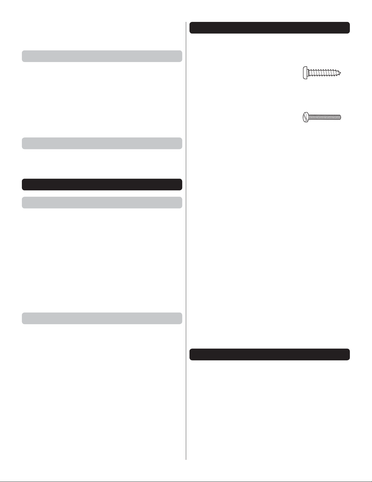
● There are three types of screws used in this kit:
Sheet Metal Screws are designated by a number and a
length. For example #6 3/4" [19mm].
This is a number six screw
that is 3/4" [19mm] long.
Machine Screws are designated by a number,
threads per inch, and a length. For example
4-40 3/4" [19mm].
This is a number four screw
that is 3/4" [19mm] long with
forty threads per inch.
● When you see the term test fi t in the instructions, it means
that you should fi rst position the part on the assembly
without using any glue, then slightly modify or custom
fi t the part as necessary for the best fi t.
● Whenever the term glue is written you should rely upon
your experience to decide what type of glue to use. When
a specifi c type of adhesive works best for that step, the
instructions will make a recommendation.
● We recommend 30-minute epoxy only, because you will
need the working time or the additional strength.
● Photos and sketches are placed before the step they refer
to. Frequently you can study photos in following steps to
get another view of the same parts.
● The Extra 300SP EP is factory-covered with Top Flite
MonoKote fi lm. Should repairs ever be required, MonoKote
can be patched with additional MonoKote purchased
separately. MonoKote is packaged in six-foot rolls, but
some hobby shops also sell it by the foot. If only a small
piece of MonoKote is needed for a minor patch, perhaps a
fellow modeler would give you some. MonoKote is applied
with a model airplane covering iron, but in an emergency a
regular iron could be used. A roll of MonoKote includes full
instructions for application. Following are the colors used
on this model and order numbers for six foot rolls.
TOPQ0203 - Yellow TOPQ0202 - Orange
TOPQ0221 - Royal Blue TOPQ0201 - Missile Red
KIT INSPECTION
Before starting to build, take an inventory of this kit to make
sure it is complete, and inspect the parts to make sure they
are of acceptable quality. If any parts are missing or are not
of acceptable quality, or if you need assistance with assembly,
contact Product Support. When reporting defective or missing
parts, use the part names exactly as they are written in the
Kit Contents list.
Great Planes Product Support
3002 N Apollo Drive, Suite 1 Ph: (217) 398-8970, ext. 5
Champaign, IL 61822 Fax: (217) 398-7721
E-mail: airsupport@greatplanes.com
4
ORDERING REPLACEMENT PARTS
Replacement parts for the Great Planes Extra 300SP EP ARF
are available using the order numbers in the Replacement
Parts List that follows. The fastest, most economical service
can be provided by your hobby dealer or mail-order company.
Be certain to specify the order number exactly as listed in the
Replacement Parts List. Payment by credit card or personal
check only; no C.O.D.
If additional assistance is required for any reason contact
Product Support by e-mail at productsupport@greatplanes.
com, or by telephone at (217) 398-8970.
To locate a hobby dealer, visit the Hobbico web site at www.
hobbico.com. Choose “Where to Buy” at the bottom of the menu
on the left side of the page. Follow the instructions provided
on the page to locate a U.S., Canadian or International dealer.
If a hobby shop is not available, replacement parts may also
be ordered from Tower Hobbies at www.towerhobbies.com,
or by calling toll free (800) 637-6050.
Parts may also be ordered directly from Hobby Services by
calling (217) 398-0007, or via facsimile at (217) 398-7721, but
full retail prices and shipping and handling charges will apply.
Illinois and Nevada residents will also be charged sales tax. If
ordering via fax, include a Visa® or MasterCard® number and
expiration date for payment.
Mail parts orders Hobby Services
and payments by 3002 N Apollo Drive, Suite 1
personal check to: Champaign IL 61822
KIT CONTENTS
REPLACEMENT PARTS LIST
Order No. Description
GPMA5350
GPMA5351
GPMA5352
GPMA5353
GPMA5354
GPMA5355
GPMA5356
GPMA5357
GPMA5358
GPMA5359
GPMA5360
Wing
Fuselage
Tail Surface Set
Canopy
Landing Gear
Wheel Pants
Spinner
Cowl
Wing Tube
Decals
Wing Bolts
5
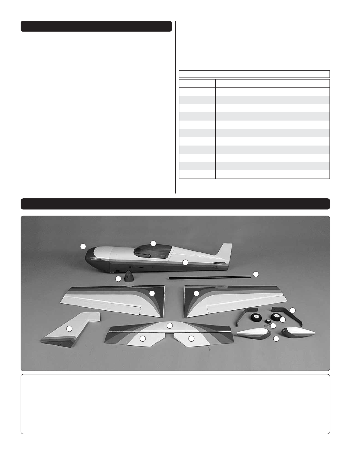
Kit Contents
1. Cowl
2. Fuselage
3. Canopy Hatch
4. Wing / Ailerons
5. Rudder
1
8
6. Horizontal Stabilizer
7. Elevator Halves
8. Spinner
3
2
4 4
6
7 7
13
9
10
12
11
11. Wheel Pants
12. Tail Wheel Assembly
13. Wing Tube
9. Landing Gear
10. Wheels
5
PREPARATIONS
1. If you have not done so already, remove the major
❏
parts of the kit from the box and inspect for damage. If any
parts are damaged or missing, contact Product Support at
the address or telephone number listed in the “Kit Inspection”
section on page 4.
2. Remove the tape and separate the elevators from the
❏
stab. Use a covering iron with a covering sock on medium
heat to tighten the covering on the wings, fuselage, etc. if
necessary. Apply pressure over sheeted areas to thoroughly
bond the covering to the wood. CAUTION: The Extra 300SP
EP was designed to be strong where needed, but lightweight
for excellent fl ight performance. Care must be taken when
assembling the plane to avoid damage.
ASSEMBLE THE WINGS
Install the Ailerons
Do the right wing fi rst so your work matches the photos
the fi rst time through.
Install the Aileron Servos & Pushrods
3. Install the servo into the servo opening. Drill a 1/16"
❏ ❏
[1.6 mm] hole through each of the mounting holes in the servo.
Install and then remove a servo mounting screw into each of
the holes you have drilled. Apply a drop of thin CA into the
holes to harden the threads. Once the glue has cured install
the servo into the servo opening using the hardware included
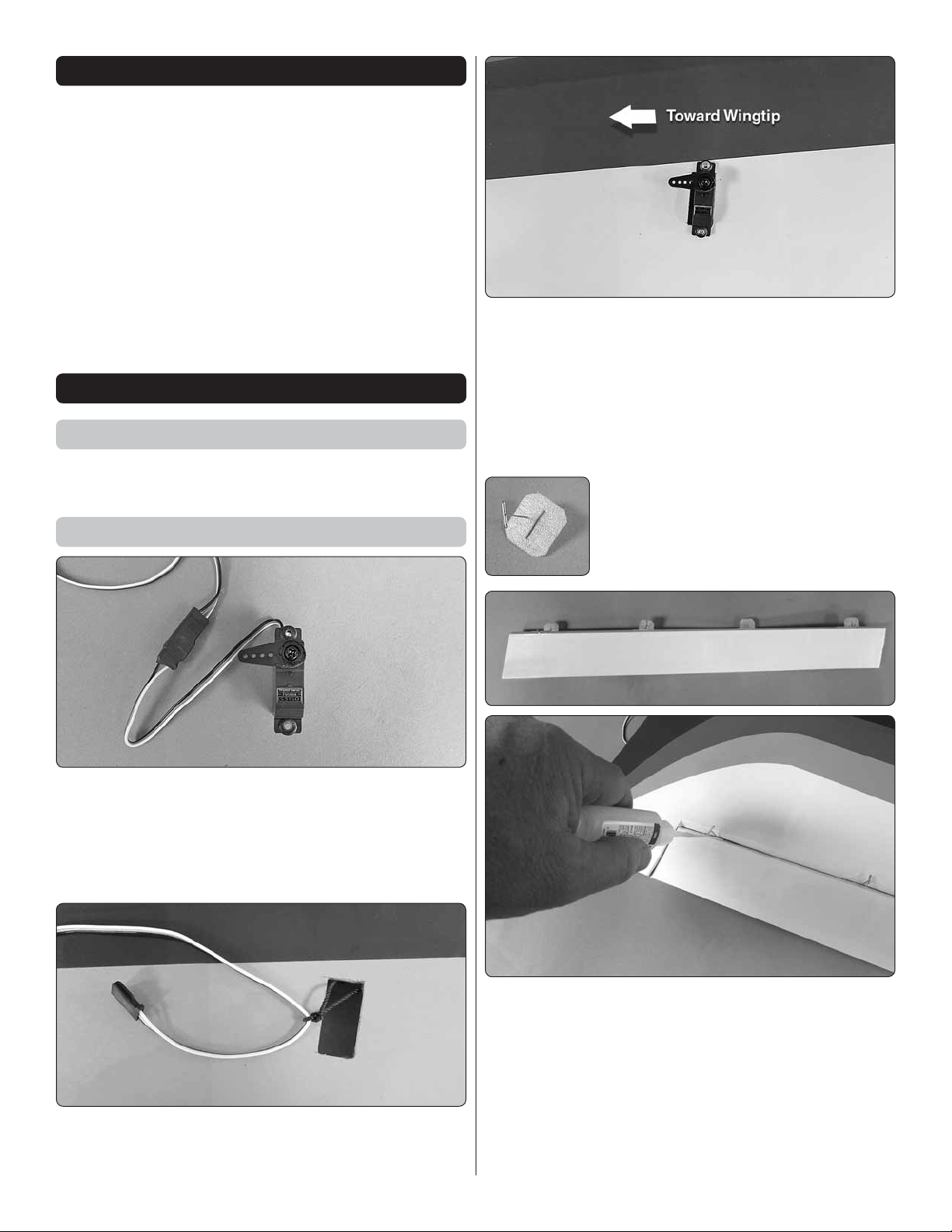
with your servo. Center the servo and then install a servo arm
as shown. The arm should be pointing towards the wingtip.
4. Install a pin into the center of four
❏ ❏
hinges. This will keep the hinge centered in
the slots of the wing and aileron.
1. Install the mounting hardware that came with your
❏ ❏
servo to the servo. Cut three arms from a four arm servo
horn, center the servo and install the arm as shown. Install
a 16" [400mm] servo extension onto the servo lead. Secure
the extension to the lead with tape, a piece of shrink tube or
some other method to keep them from coming unplugged.
2. Inside the wing a string is taped. Remove the tape and
❏ ❏
then tie the string to the servo extension. Pull the string and
the servo lead through the wing. Untie the string from the lead.
5. Install the hinges into the four slots in the aileron
❏ ❏
and then install the aileron to the wing. Center the aileron in
the wing and be sure the hinges are all positioned properly
in the slots. When you are satisfi ed with the installation of the
aileron apply a couple of drops of thin CA glue onto each side
of the four hinges. Allow the glue to completely harden and
then remove the pins. Do not apply CA accelerator. This
will cause the hinge to get brittle and possibly break. Test the
hinges by pulling on the aileron and use more CA to secure
them, if needed.
6
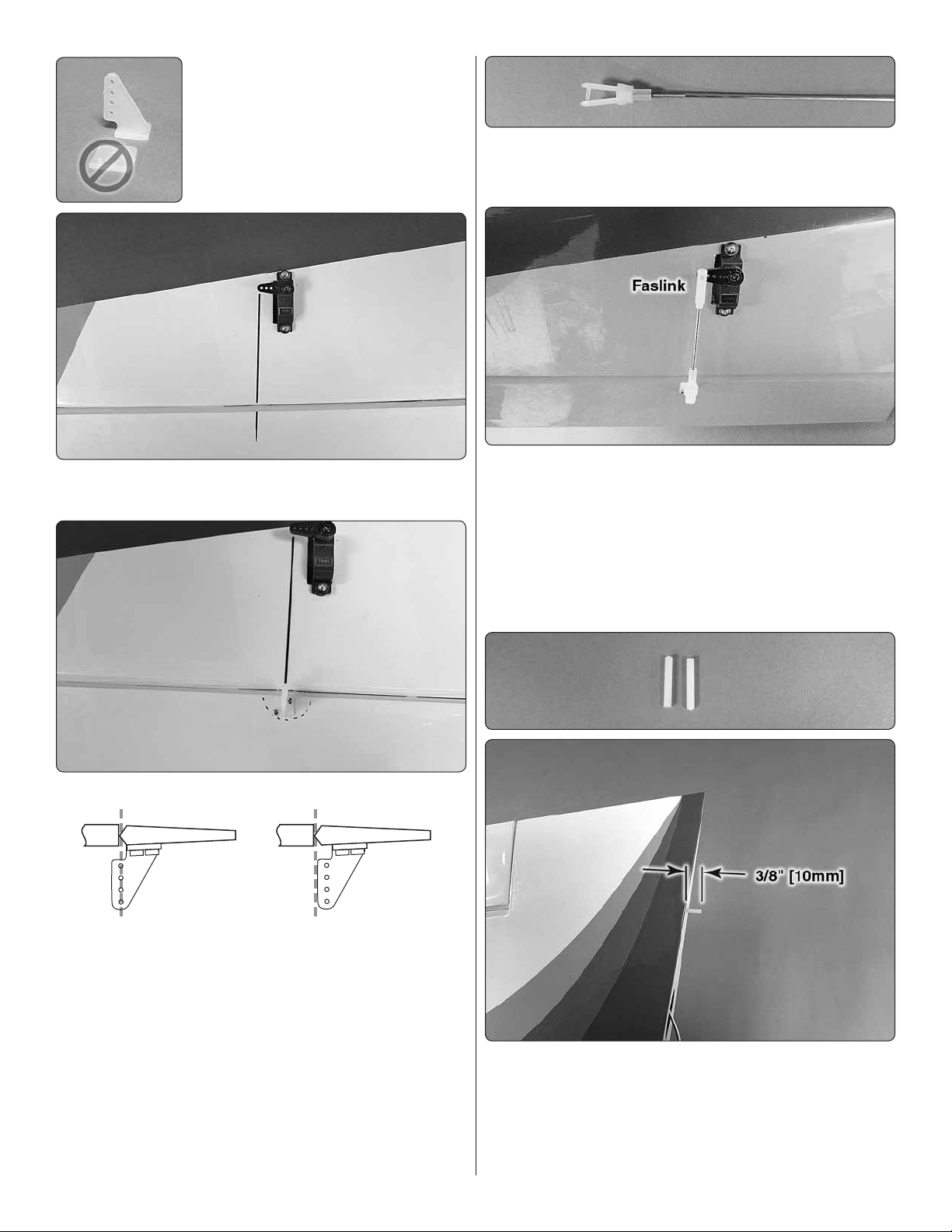
6. Remove the fl at nylon mounting
Hinge Line Hinge Line
Correct Incorrect
❏ ❏
plate from the clevis. The fl at plate can
be discarded.
7. Using a felt tip marker, draw a line from the servo
❏ ❏
arm to the aileron.
10. Thread a nylon clevis, 20 turns, onto a 6" [152 mm]
❏ ❏
wire pushrod. Slide a silicone clevis retainer over the clevis.
Attach the clevis in the outer hole of a nylon control horn.
11. With the aileron servo and the aileron centered, mark
❏ ❏
the aileron pushrod where it crosses the aileron servo arm.
Make a 90° bend at the mark. Cut the pushrod 3/8" [9.5mm]
past the bend. Drill a 5/64" [2 mm] hole in the outer hole of
the control arm of the servo. This should be the hole that is
approximately 5/8" [16 mm] from the center of the servo. Attach
the pushrod to the aileron servo arm with a nylon Faslink.
8. Place the nylon control horn onto the aileron in line
❏ ❏
with the line you drew and using the sketch to properly place
the hinge. Be sure the control horn is placed over the shaped
hardwood. (Look closely and this will be visible under the
covering).
9. Mark the location of the mounting holes onto the
❏ ❏
aileron. Drill a 1/16" [1.6mm] hole on the marks, drilling through
the plywood plate but not through the top of the aileron.
Install and then remove a #2 3/8" screw into each of the
holes you have drilled. Apply a drop of thin CA into the holes
to harden the threads. Once the glue has cured secure the
control horn to the aileron with the screws.
12. Repeat steps 1-11 for the left wing panel.
❏
13. Included with the kit are two 1/8" 7/8" [3mm
❏ ❏
22 mm] smooth nylon pins. (There is another ribbed nylon
pin in the kit. Do not confuse the two.) Epoxy a pin into the
root rib of each of the wing panels. When you install the pin
it will stop when fully inserted in the hole. Approximately 3/8"
[10 mm] of the pin will extend outside of the root rib.
7
ASSEMBLE THE FUSELAGE
Note: If you have not already fi gured out how to remove the
canopy, the magnets at the rear of the canopy keep it locked
in place. Lift the back of the canopy to remove it.
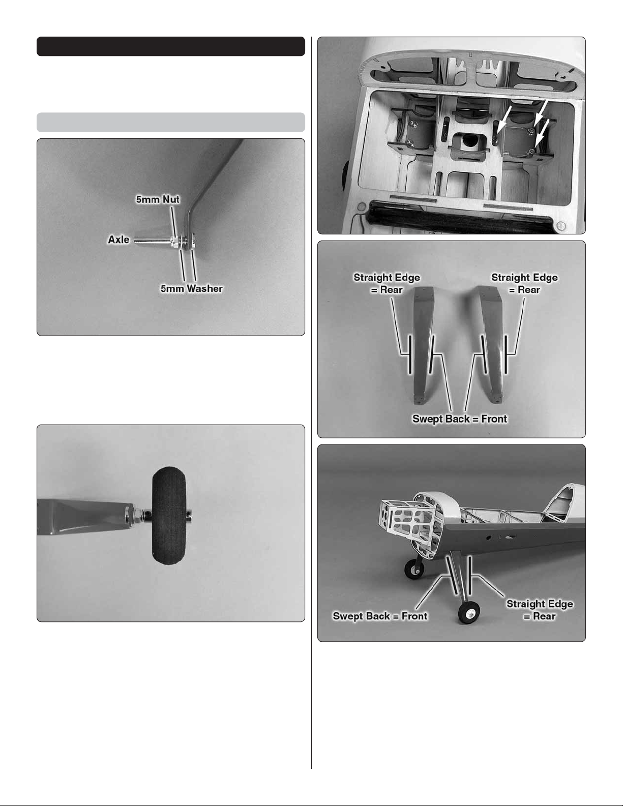
Install the Main Landing Gear
1. Slide a 5mm washer onto the axle. Insert a 4mm axle
❏ ❏
through the right main landing gear. Slide a 5mm washer
onto the axle followed by the 5 mm lock nut and the wheel.
(All of these need to be slid into position before securing the
assembly to the wheel pant). Tighten the axle nut to secure
the axle to the landing gear. Do this for both landing gears.
2. Apply a drop of thread locker to two 6-32 set screws
❏ ❏
and thread them into two 5/32" [4 mm] wheel collars. Slide
one wheel collar onto the axle followed by the wheel and then
the second wheel collar. Tighten the set screws against the
axle. Be sure the wheel spins freely after the wheel collar is
in place. Do this for both axles.
3. Attach the main landing gear to the fuselage with
❏ ❏
three 4- 40 ½" SHC screws, #4 lock washers and #4 fl at
washers. Note: The front of the main landing gear sweeps
back, while the back of the gear is straight. Do this for both
landing gear halves.
8
 Loading...