

Page 1
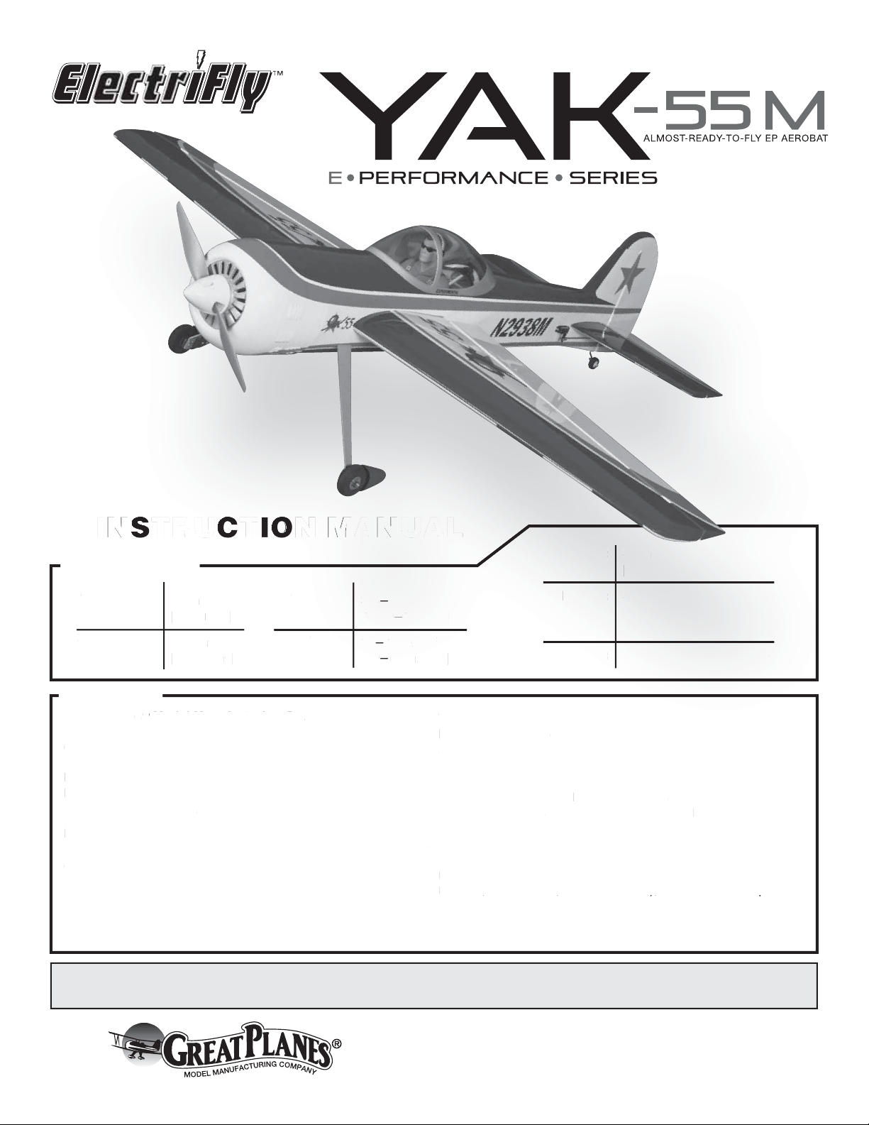
INSTRUCTION MANUAL
WARRANTY
G
e
s
®
Model Manufacturing Co.
f
p
.
T
3
C
SA
n
]
)
:
)
:
]
:
:
b
g]
g
S
PECIFICATION
SPECIFICATIONS
Wingspan
Wingspan:
Wing Area:
Wing Area
1 in
51 in
mm
[1295mm]
2
in
508 in
[32.8 dm2]
32.8 dm
WARRANTY
Great Planes® Model Manufacturing Co. guarantees this kit to
reat Plan
be free from defects in both material and workmanship at the
be free from defects in both material and workmanship at the
date of purchase. This warranty does not cover any component
date of purchase. This warranty does not cover any component
parts damaged by use or modification. In no case shall Great
parts damaged by use or modification. In no case shall Great
Planes’ liability exceed the original cost of the purchased kit.
Planes’ liability exceed the original cost of the purchased kit.
Further, Great Planes reserves the right to change or modify this
Further, Great Planes reserves the right to change or modify this
warranty without notice.
warranty without notice.
In that Great Planes has no control over the final assembly or
In that Great Planes has no control over the final assembly or
material used for final assembly, no liability shall be assumed nor
material used for final assembly, no liability shall be assumed nor
accepted for any damage resulting from the use by the user o
accepted for any damage resulting from the use by the user of
the final user-assembled product. By the act of using the
the final user-assembled product. By the act of using the
user-assembled product, the user accepts all resulting liability.
If the buyer is not prepared to accept the liability associated
with the use of this product, the buyer is advised to return
Weight
Weight:
.5
3.5– 3.75 lb
[1590 – 1700 g]
Wing
Win
Loading:
Loading:
guarantees this kit to
16– 17 oz /ft
[49– 52 g/dm2]
49
.75 l
700
7 o/ft
/dm
Length: 47 in
ength:47 i
[1195mm]
119 5mm
4-Channel minimum or
Radio:
Radio:
2
Motor/ESC/Prop: RimFire .32 (42-50-800)
otor/ESC/Prop
this kit immediately in new and unused condition to the
this kit immediately in new and unused condition to the
place of purchase.
lace of purchase
To make a warranty claim send the defective part or item to
o make a warranty claim send the defective part or item to
Hobby Services at the address below:
Hobby Services at the address below:
Hobby Services
Hobby Services
3002 N. Apollo Dr. Suite 1
002 N. Apollo Dr. Suite 1
Champaign IL 61822 USA
hampaign IL 61822 U
Include a letter stating your name, return shipping address, as
Include a letter stating your name, return shipping address, as
much contact information as possible (daytime telephone
much contact information as possible (daytime telephone
number, fax number, e-mail address), a detailed description of
number, fax number, e-mail address), a detailed description of
the problem and a photocopy of the purchase receipt. Upon
receipt of the package the problem will be evaluated as quickly
as possible.
4-Channel minimum or
5-Channel with mixing
-Channel with mixing
(for separate ailerons)
(for separate ailerons
imFire .32 (42-50-800
READ THROUGH THIS MANUAL BEFORE STARTING CONSTRUCTION. IT CONTAINS IMPORTANT
INSTRUCTIONS AND WARNINGS CONCERNING THE ASSEMBLY AND USE OF THIS MODEL.
© 2010 Hobbico®, Inc. GPMA1186 Mnl
Champaign, Illinois
(217) 398-8970, Ext 5
airsupport@greatplanes.com
Page 2

TABLE OF CONTENTS
INTRODUCTION
INTRODUCTION . . . . . . . . . . . . . . . . . . . . . . . . . . . . . . . .2
AMA . . . . . . . . . . . . . . . . . . . . . . . . . . . . . . . . . . . . . . . . . .2
SAFETY PRECAUTIONS . . . . . . . . . . . . . . . . . . . . . . . . .2
DECISIONS YOU MUST MAKE . . . . . . . . . . . . . . . . . . . . . 3
Radio Equipment . . . . . . . . . . . . . . . . . . . . . . . . . . . . .3
Motor/ESC Recommendation . . . . . . . . . . . . . . . . . . .3
Propeller. . . . . . . . . . . . . . . . . . . . . . . . . . . . . . . . . . . .3
Recommended Batteries . . . . . . . . . . . . . . . . . . . . . . .3
Recommended Charger. . . . . . . . . . . . . . . . . . . . . . . .3
ADDITIONAL ITEMS REQUIRED . . . . . . . . . . . . . . . . . . .4
Adhesives and Building Supplies. . . . . . . . . . . . . . . . .4
Optional Supplies and Tools. . . . . . . . . . . . . . . . . . . . .4
IMPORTANT BUILDING NOTES. . . . . . . . . . . . . . . . . . . .4
KIT INSPECTION. . . . . . . . . . . . . . . . . . . . . . . . . . . . . . . . 4
ORDERING REPLACEMENT PARTS . . . . . . . . . . . . . . . . 5
KIT CONTENTS. . . . . . . . . . . . . . . . . . . . . . . . . . . . . . . . .5
PREPARATIONS . . . . . . . . . . . . . . . . . . . . . . . . . . . . . . . .6
ASSEMBLE THE WINGS. . . . . . . . . . . . . . . . . . . . . . . . . .6
ASSEMBLE THE FUSELAGE . . . . . . . . . . . . . . . . . . . . . .7
Install the Stabilizer . . . . . . . . . . . . . . . . . . . . . . . . . . .7
Install the Elevators . . . . . . . . . . . . . . . . . . . . . . . . . . .8
Install the Rudder. . . . . . . . . . . . . . . . . . . . . . . . . . . . .9
Install the Main Landing Gear . . . . . . . . . . . . . . . . . . .9
Install the Motor . . . . . . . . . . . . . . . . . . . . . . . . . . . . .10
INSTALL THE RADIO SYSTEM . . . . . . . . . . . . . . . . . . .11
Install the Elevator Servo . . . . . . . . . . . . . . . . . . . . . .11
Install the Rudder Servo . . . . . . . . . . . . . . . . . . . . . .12
Install the Cowl. . . . . . . . . . . . . . . . . . . . . . . . . . . . . .13
Apply the Decals . . . . . . . . . . . . . . . . . . . . . . . . . . . .14
GET THE MODEL READY TO FLY . . . . . . . . . . . . . . . . .14
Check the Control Directions . . . . . . . . . . . . . . . . . . .14
Set the Control Throws. . . . . . . . . . . . . . . . . . . . . . . .15
Finish the Model. . . . . . . . . . . . . . . . . . . . . . . . . . . . .16
Balance the Model (C.G.). . . . . . . . . . . . . . . . . . . . . .16
Balance the Model Laterally. . . . . . . . . . . . . . . . . . . .16
PREFLIGHT . . . . . . . . . . . . . . . . . . . . . . . . . . . . . . . . . . .16
Identify Your Model. . . . . . . . . . . . . . . . . . . . . . . . . . .16
Charge the Batteries . . . . . . . . . . . . . . . . . . . . . . . . .16
Balance Propellers. . . . . . . . . . . . . . . . . . . . . . . . . . .17
Range Check . . . . . . . . . . . . . . . . . . . . . . . . . . . . . . .17
MOTOR SAFETY PRECAUTIONS . . . . . . . . . . . . . . . . .17
LITHIUM BATTERY HANDLING AND USAGE . . . . . . . .17
AMA SAFETY CODE. . . . . . . . . . . . . . . . . . . . . . . . . . . . 18
CHECK LIST . . . . . . . . . . . . . . . . . . . . . . . . . . . . . . . . . .18
FLIGHT NOTES . . . . . . . . . . . . . . . . . . . . . . . . . . . . . . . .19
The full scale Yakovlev Yak-55M EP is a low cost, advanced
aerobatic aircraft. ElectriFly has taken the best qualities of the
full scale Yak-55M and reduced it down to a light weight, 51"
electric powered ARF. The ElectriFly Yak-55M EP flies great
and looks great. Now you can practice for IMAC competition
without risking your larger, more expensive planes.
For the latest technical updates or manual corrections to
the Yak-55M EP visit the Great Planes web site at www.
greatplanes.com. Open the “Airplanes” link, then select the
Yak-55M EP ARF. If there is new technical information or
changes to this model a “tech notice” box will appear in the
upper left corner of the page.
AMA
Academy of Model Aeronautics:If you are not already a
member of the AMA, please join! The AMA is the governing
body of model aviation and membership provides liability
insurance coverage, protects modelers’ rights and interests
and is required to fly at most R/C sites.
Academy of Model
Aeronautics
5151 East Memorial Drive
Muncie, IN 47302-9252
Tele. (800) 435-9262
Fax (765) 741-0057
www.modelaircraft.org
IMPORTANT!!!
Two of the most important things you can do to preserve the
radio controlled aircraft hobby are to avoid flying near fullscale aircraft and avoid flying near or over groups of people.
PROTECT YOUR MODEL, YOURSELF
& OTHERS… FOLLOW THESE
IMPORTANT SAFETY PRECAUTIONS
1. Your Yak-55M EP should not be considered a toy, but rather
a sophisticated, working model that functions very much like
a full-size airplane. Because of its performance capabilities,
the Yak-55M EP, if not assembled and operated correctly,
could possibly cause injury to yourself or spectators and
damage to property.
2. You must assemble the model according to the instructions.
Do not alter or modify the model, as doing so may result in an
unsafe or unflyable model. In a few cases the instructions may
differ slightly from the photos. In those instances the written
instructions should be considered as correct.
3. You must take time to build straight, true and strong.
4. You must use an R/C radio system that is in first-class
condition, and a correctly sized motor and components
(wheels, etc.) throughout the building process.
2
Page 3

5. You must correctly install all R/C and other components
so that the model operates correctly on the ground and in
the air.
6. You must check the operation of the model before every
flight to insure that all equipment is operating and that the
model has remained structurally sound. Be sure to check
clevises or other connectors often and replace them if they
show any signs of wear or fatigue.
7. If you are not an experienced pilot or have not flown
this type of model before, we recommend that you get the
assistance of an experienced pilot in your R/C club for your
first flights. If you’re not a member of a club, your local
hobby shop has information about clubs in your area whose
membership includes experienced pilots.
8. WARNING: The cowl and wheel pants included in this kit
are made of fiberglass, the fibers of which may cause eye,
skin and respiratory tract irritation. Never blow into a part
(wheel pant, cowl) to remove fiberglass dust, as the dust
will blow back into your eyes. Always wear safety goggles, a
particle mask and rubber gloves when grinding, drilling and
sanding fiberglass parts. Vacuum the parts and the work
area thoroughly after working with fiberglass parts.
Motor/ESC Recommendations
The recommended motor and speed control for the Yak-55M
EP is a RimFire™ .32 (42-50-800) brushless outrunner motor
and the SS-45A Brushless ESC.
Great Planes RimFire .32 Brushless Outrunner Motor
❏
[GPMG4700]
Great Planes Silver Series SS-45A Brushless ESC
❏
[GPMM1840]]
Propeller
If using the recommended RimFire .32 Outrunner Motor, we
suggest an APC 12x6E electric propeller [APCQ4130].
Recommended Batteries
If using the suggested motor and prop combination, a
2200mAh 14.8V LiPo battery pack is recommended.
We, as the kit manufacturer, provide you with a top quality,
thoroughly tested kit and instructions, but ultimately the
quality and fl yability of your fi nished model depends
on how you build it; therefore, we cannot in any way
guarantee the performance of your completed model,
and no representations are expressed or implied as to the
performance or safety of your completed model.
Remember: Take your time and follow the instructions to
end up with a well-built model that is straight and true.
DECISIONS YOU MUST MAKE
Radio Equipment
The Yak-55M EP requires a 4-channel radio system with four
micro servos such as the Futaba® S3115 Micro Precision
Servo. For optimum performance, we recommend the Futaba
S3150 Slim Digital Servos.
In addition, three 9" [229mm] servo extensions are required
for the aileron servos and the ESC. Two 16" [405mm] servo
extensions are required for the rudder and elevator servos.
If you are using a radio system that does not support mixing
functions, a Y-harness will also be required to connect the
aileron servos to the receiver.
(4) Futaba S3115 Micro Precision Servos [FUTM0415]
❏
[38.9 oz-in (2.8 kg-cm) of torque]
OR
(4) Futaba S3150 Slim Digital Servos [FUTM0303]
❏
[51.4 oz-in (3.7 kg-cm) of torque]
PLUS
(1) "Y" harness [FUTM4130]
❏
(2) 16" extensions [FUTM3955]
❏
(3) 9" extensions [FUTM3910]
❏
❏
Great Planes ElectriFly LiPo 14.8V 2200mAh 25C
(GPMP0521)
OR
❏
FlightPower® LiPo EOUX30 14.8V 2200mAh 30C
(FPWP6199)
Recommended Charger
A LiPo compatible charger is required to charge LiPo
batteries. The Great Planes ElectriFly PolyCharge4™ is
designed for LiPo packs only; however, it is able to charge
four LiPo packs simultaneously. The ElectriFly Triton2™ and
AC/DC Triton2 EQ chargers will only charge one pack at a
time, but are capable of charging NiCd, NiMH, Pb acid and
LiPo batteries.
❏
Great Planes PolyCharge4 DC-Only 4 Output LiPo
Charger (GPMM3015)
OR
❏
Great Planes ElectriFly Triton2 DC Computer Peak
Charger (GPMM3153)
OR
❏
Great Planes AC/DC Triton2 EQ Charger/Balancer
(GPMM3156)
Throughout the life of a LiPo battery, the individual cells
located inside the battery may become unbalanced. These
unbalanced cells can shorten the life of the battery or cause
it to malfunction. For this reason, it is always recommended
that a cell balancer be used when charging LiPo batteries.
The ElectriFly Equinox™ is a cell balancer that may be used
with any LiPo charger and is capable of maintaining the cell
balance of the battery. Note: The AC/DC Triton2 EQ does not
require a cell balancer.
❏
Great Planes ElectriFly Equinox LiPo Cell Balancer
[GPMM3160]
3
Page 4
ADDITIONAL ITEMS REQUIRED
IMPORTANT BUILDING NOTES
Adhesives and Building Supplies
This is the list of adhesives and building supplies required
to finish the Yak-55M EP. Order numbers are provided in
parentheses.
1/2 oz. [15g] Thin Pro™ CA (GPMR6001)
❏
Pro 30-minute epoxy (GPMR6043)
❏
Threadlocker thread locking cement (GPMR6060)
❏
Denatured alcohol (for epoxy clean up)
❏
Paper towels
❏
Drill bits: 1/16" [1.6mm], 3/32" [2.4mm]
❏
#1 Hobby knife (RMXR6903)
❏
#11 blades (5-pack RMXR6930)
❏
Small T-pins (100, HCAR5100)
❏
Tape measure
❏
Pliers with wire cutter (HCAR0625)
❏
Phillips Head screw driver
❏
Masking tape
❏
Metal cutting file
❏
Optional Supplies and Tools
Here is a list of optional tools mentioned in the manual that
will help you build the Yak-55M EP.
2 oz. [57g] spray CA activator (GPMR6035)
❏
CA applicator tips (HCAR3780)
❏
CA debonder (GPMR6039)
❏
Pro 6-minute epoxy (GPMR6042)
❏
Epoxy brushes (6, GPMR8060)
❏
Mixing sticks (50, GPMR8055)
❏
Mixing cups (GPMR8056)
❏
AccuThrow™ Deflection Gauge (GPMR2405)
❏
CG Machine™ (GPMR2400)
❏
21st Century® sealing iron [COCR2700]
❏
21st Century iron cover [COVR2702]
❏
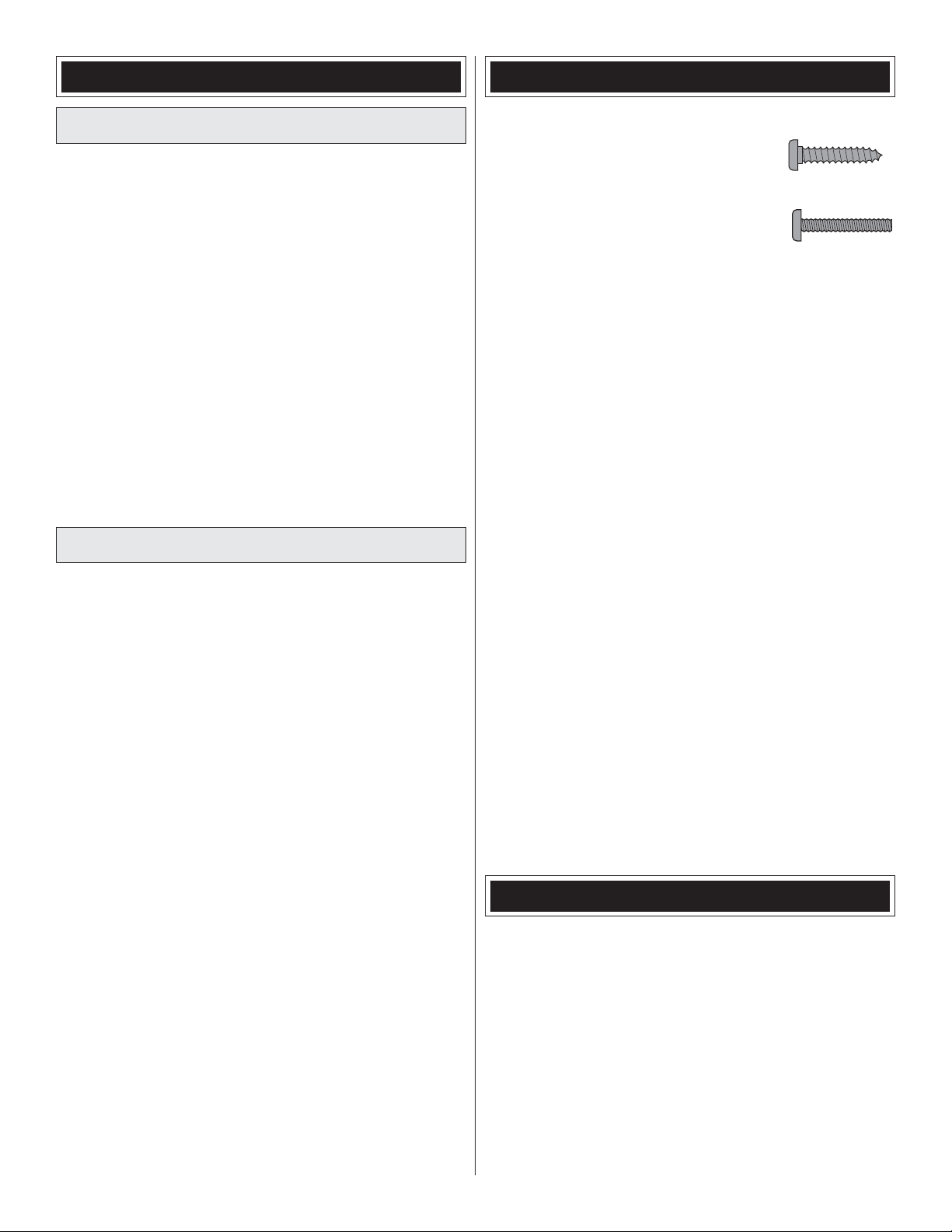
• There are three types of screws used in this kit:
Sheet metal screws are designated by
a number and a length. For example,
#6 x 3/4" [19mm]
Machine screws are designated by a
number, threads per inch, and a length.
For example 4-40 x 3/4" [19mm]
• When you see the term test fit in the instructions, it means
that you should first position the part on the assembly
without using any glue, and then slightly modify or custom
fit the part as necessary for the best fit.
• Whenever the term glue is written you should rely upon
your experience to decide what type of glue to use. When
a specific type of adhesive works best for that step, the
instructions will make a recommendation.
• We recommend 30-minute epoxy to install the stabilizer,
because you will need the working time. 6-minute epoxy can
be used for the remaining assembly, but 30-minute epoxy
can also be used.
• Photos and sketches are placed before the step they
refer to. Frequently you can study photos in following steps
to get another view of the same parts.
• The Yak-55M EP is factory-covered with Top Flite
MonoKote® film. Should repairs ever be required, MonoKote
can be patched with additional MonoKote purchased
separately. MonoKote is packaged in six-foot rolls, but
some hobby shops also sell it by the foot. If only a small
piece of MonoKote is needed for a minor patch, perhaps a
fellow modeler would give you some. MonoKote is applied
with a model airplane covering iron, but in an emergency a
regular iron could be used. A roll of MonoKote includes full
instructions for application. Following are the colors used on
this model and order numbers for six foot rolls.
White (TOPOQ0204)
Sapphire Blue (TOPQ0226)
True Red (TOPQ0227)
®
KIT INSPECTION
Before starting to build, take an inventory of this kit to make
sure it is complete, and inspect the parts to make sure they
are of acceptable quality. If any parts are missing or are not of
acceptable quality, or if you need assistance with assembly,
contact Product Support. When reporting defective or
missing parts, use the part names exactly as they are written
in the Kit Contents list.
Great Planes Product Support:
3002 N Apollo Drive, Suite 1
Champaign, IL 61822
Telephone: (217) 398-8970, ext. 5
Fax: (217) 398-7721
E-mail: airsupport@greatplanes.com
4
Page 5
ORDERING REPLACEMENT PARTS
Replacement parts for the Yak-55M EP ARF are available
using the order numbers in the Replacement Parts List
that follows. The fastest, most economical service can be
provided by your hobby dealer or mail-order company.
To locate a hobby dealer, visit the Great Planes web site
at www.greatplanes.com. Choose “Where to Buy” at the
bottom of the menu on the left side of the page. Follow the
instructions provided on the page to locate a U.S., Canadian
or International dealer.
Parts may also be ordered directly from Hobby Services
by calling (217) 398-0007, or fax at (217) 398-7721, but full
retail prices and shipping and handling charges will apply.
Illinois and Nevada residents will also be charged sales tax.
If ordering via fax, include a Visa
and expiration date for payment.
Mail parts orders and payments by personal check to:
Hobby Services
3002 N. Apollo Drive, Suite 1
Champaign, IL 61822
Be certain to specify the order number exactly as listed in
the Replacement Parts List. Payment by credit card or
personal check only; no C.O.D.
If additional assistance is required for any reason, contact
Product Support by telephone at (217) 398-8970, or by
e-mail at productsupport@greatplanes.com.
®
or MasterCard® number
REPLACEMENT PARTS LIST
Order No. Description
GPMA4100
GPMA4101
GPMA4102
GPMA4103
GPMA4105
GPMA4106
GPMA4107
GPMA4108
GPMA4109
GPMA4110
GPMA4111
GPMA4112
NOTE
Fuselage
Wing
Horizontal Stab
Rudder
Canopy/Hatch
Cowl
Landing Gear
Wheel Spats
Decals
Wing Joiner Rod
Wing Screws (2)
Tailwheel Assembly
Full-size plans are not available.
You can download a copy of this
manual at www.greatplanes.com.
13
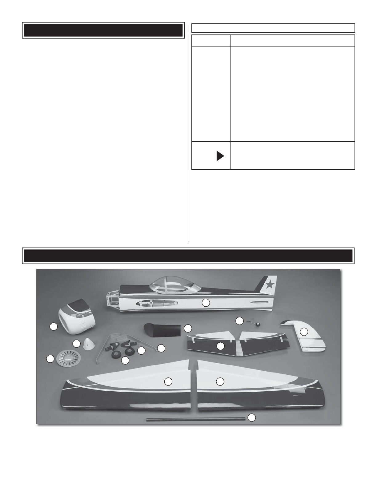
KIT CONTENTS
3
6
11
8
9
7
10
2
1. Left Wing
2. Right Wing
3. Fuselage
4. Stabilizer
5. Rudder
6. Cowl
7. Cockpit fl oor
8. Left & Right Wheel Pant
9. Left & Right Main Landing Gear
10. Wheels (2)
5
14
5
4
1
12
11. Spinner
12. Wing Tube
13. Cowl Louvers
14. Tail gear
Page 6

PREPARATIONS
1. If you have not done so already, remove the major parts
❏
of the kit from the box and inspect for damage. If any parts
are damaged or missing, contact Product Support at the
address or telephone number listed in the "Kit Inspection"
section on page 4.
2. Remove the parts from the bags. Use a covering iron
❏
with a covering sock on medium heat to tighten the covering if
necessary. Apply pressure over sheeted areas to thoroughly
bond the covering to the wood.
3. Install the servo into the servo opening. Drill through
❏ ❏
the servo mounting holes with a 1/16" [1.6mm] drill bit.
Remove the servo from the servo opening. Install and then
remove a servo mounting screw into each of the holes you
have drilled. Apply a drop of thin CA into the holes to harden
the threads. Once the glue has cured install the servo into the
servo opening. Do not install the brass grommets or rubber
bushings in the servo. Secure the servo to the wing with the
servo mounting screws and #2 flat washers. Center the servo
and then install a servo arm as shown. The arm should be
pointing towards the wingtip, parallel with the aileron hinge line.
ASSEMBLE THE WINGS
Do the right wing first so your work matches the photos the
first time through.
1. Install a 9" servo extension onto the servo lead. Secure
❏ ❏
the extension to the lead with tape, a piece of shrink tube or
some other method to keep them from coming unplugged.
2. Insert the servo lead in the aileron servo opening
❏ ❏
and route the lead out the root of the wing. NOTE: The
Futaba S3150 servo is 2mm longer than the S3115 servo. If
the S3150 servo is installed, both ends of the aileron servo
opening will need to be trimmed approximately 1/32" [1mm].
4. Thread a nylon clevis, 16 turns, onto a 6" [152mm]
❏ ❏
wire pushrod.
CORRECT INCORRECT
Hinge Line Hinge Line
5. Attach the clevis in the outer hole of a nylon control
❏ ❏
horn. Place the control horn in line with the outer hole in the
servo arm. When positioned properly the control horn will
6
Page 7

rest on a hardwood block in the aileron. Mark the location
of the mounting holes onto the aileron. Drill a 1/16" [3.2mm]
hole on the marks, approximately 3/8" [9.5mm] deep. Do not
drill completely through the top of the aileron.
6. Thread two #2 x 3/8" [9.5mm] self-tapping screws
❏ ❏
through the control horn, into the aileron control horn block.
Remove the two screws and harden the screw holes in the
aileron with thin CA. After the CA has cured, reinstall the
control horn.
8. Use thin CA to glue the two plastic wing alignment
❏ ❏
pins in the root rib. The pins should protrude from the rib
approximately 1/4" [6.4mm].
9. Repeat steps 1-8 for the left wing panel.
❏
ASSEMBLE THE FUSELAGE
7. Slide a silicone clevis retainer over the clevis. With
❏ ❏
the aileron servo and the aileron centered, mark the aileron
pushrod where it crosses the aileron servo arm. Make a 90°
bend at the mark. Cut the pushrod 3/8" [9.5mm] past the
bend. Attach the pushrod to the aileron servo arm with a
nylon Faslink™.
Install the Stabilizer
1. Center the wing tube in the fuselage. Slide the wing
❏
halves onto the wing tube and secure the wing halves to the
fuselage with the aluminum thumb screws.
7
Page 8

2. Center the horizontal stabilizer, side-to-side, in the
❏
slot in the fuselage. Also measure the distance from the tips
of the stab to the center of the fuselage. Adjust the position
of the stab until the distance is equal.
Apply 30-minute epoxy to the wood, top and bottom. Slide the
stabilizer through the fuse so that approximately 1/2" [12.7mm]
of bare wood is showing on the other side and apply epoxy
to the wood. Now align the stabilizer, remove the masking
tape and wipe off any excess epoxy from the stabilizer and
fuselage. Recheck that the stabilizer is still aligned.
You can now remove the wings and continue with the
assembly of the fuselage.
Install the Elevators
3. Stand back and look at the stabilizer in relation to the
❏
wing. The stabilizer should be parallel with the wing. If not,
lightly sand the stabilizer saddle until the stabilizer and wings
are aligned.
1. Test fit the elevators to the stabilizer with the CA hinges.
❏
If the hinges don’t remain centered, stick a pin through the
middle of the hinge to hold it in position.
4. Insert the elevator joiner wire in the notch at the back
❏
of the stabilizer saddle. Use 30-minute epoxy to glue the
stabilizer in place, being careful that the stabilizer is properly
aligned. Tip: Place a piece of masking tape on the top and
bottom of the stabilizer, just outside the cut covering. Insert the
stabilizer in the fuse so that part of the bare wood is showing.
2. Install three CA hinges into each elevator half. Install
❏
the elevators onto the stabilizer with the elevator joiner
8
Page 9

wire in each elevator half. Check that both elevator halves
are aligned. If not, remove the elevators and while holding
one leg of the elevator joiner wire, slightly bend the other.
Reinstall the elevator halves and check again.
3. Coat the inside of the two elevator joiner wire holes and
❏
the ends of the elevator joiner wire with epoxy. Install the two
elevator halves and glue the hinges with thin CA.
Install the Rudder
Install the Main Landing Gear
1. Use epoxy to glue the tail gear bearing in the aft end
❏
of the fuselage. Make sure the tail gear wire is aligned with
the hinge line.
2. Install the three CA hinges into the rudder. Insert the
❏
tail gear wire in the rudder and check the fit of the rudder on
the fin. Use pins to hold the CA hinges in position.
3. Coat the inside of the tail gear wire hole with epoxy.
❏
Install the rudder and glue the hinges with thin CA.
1. Insert a 4mm axle through the right main landing
❏ ❏
gear. Apply a drop of thread locker on the threads of the axle.
Secure the axle to the landing gear with a 5mm nut. Note:
The front of the main landing gear sweeps forward.
2. Attach the right wheel spat to the main landing gear
❏ ❏
with two 2-56 x 3/8" machine screws, two #2 flat washers
and two 2-56 nuts. Apply threadlocker to the threads of the
machine screw before installing the nuts.
9
Page 10

3. Install a 4mm wheel collar on the axle, then the
❏ ❏
foam main wheel, followed by a second 4mm wheel collar.
Secure the wheel collars on the axle with 3mm set screws.
Mark the location where the set screw, in the outer wheel
collar, tightens on the axle and use a metal cutting file to file
a flat spot on the axle. Apply a drop of thread locker on the
set screws and reinstall the wheel collars on the axle.
Install the Motor
The Yak-55M EP has been designed to use the Great Planes
RimFire .32 Outrunner Brushless motor. If you will be installing a
different motor, you may need to modify the plywood motor box.
1. Install the RimFire motor using four 4-40 x 1/2" [12.7mm]
❏
SHC screws, four #4 lock washers and four #4 flat washers.
Before installing, apply a drop of threadlocker to the threads
of the SHC screws.
4. Attach the main landing gear to the fuselage with
❏ ❏
three 4-40 x 1/2" SHC screws, #4 lock washers and #4 flat
washers. Before installing, apply threadlocker to the threads
of the SHC screws.
5. Repeat steps 1-4 for the left main landing gear.
❏
2. Attach a 9" [229mm] servo extension to the ESC.
❏
Connect the ESC to the motor. The ESC can be attached
to the side of the motor box with adhesive-backed hook and
loop material.
3. Use a sharp hobby knife to trim the covering from over
❏
the cooling air exit hole in the bottom of the fuselage.
10
Page 11

INSTALL THE RADIO SYSTEM
Install the Elevator Servo
1. Use adhesive-backed hook and loop material to mount
❏
the receiver to the aft end of the battery tray former. Connect
the ESC to the receiver.
5. Thread a nylon clevis 16 turns onto a 2-56 x 10"
❏
[254mm] wire pushrod. Connect the clevis to a nylon
control horn. Using the elevator pushrod, position the control
horn in line with the servo arm. When positioned properly
the control horn will rest on a hardwood plate in the elevator.
Mark the location of the mounting holes onto the elevator.
Drill a 3/32" [2.4mm] hole on the marks, drilling through the
elevator. Attach the control horn to the elevator using two
2-56 x 5/8" [16mm] machine screws and the control horn
back plate.
2. Cut the covering away from the elevator servo opening
❏
on the right side of the fuselage, in front of the stabilizer.
3. Install a 16" [406mm] servo extension to the elevator
❏
servo. Secure the extension to the lead with tape, a piece of
shrink tube or some other method to keep them from coming
unplugged.
4. Install the elevator servo into the servo opening following
❏
the same procedure used to install the aileron servos. Connect
the servo to the receiver, install and center the servo arm.
6. Slide a silicone clevis retainer over the clevis. With the
❏
elevator servo and the elevator centered, mark the elevator
pushrod where it crosses the elevator servo arm. Make a
90° bend at the mark. Cut the pushrod 3/8" [9.5mm] past the
bend. Attach the pushrod to the elevator servo arm with a
nylon Faslink.
11
Page 12

Install the Rudder Servo
1. Cut the covering away from the rudder servo opening
❏
on the left side of the fuselage, in front of the stabilizer.
2. Install a 16" [406mm] servo extension to the rudder
❏
servo. Secure the extension to the lead with tape, a piece of
shrink tube or some other method to keep them from coming
unplugged.
5. Thread a nylon clevis 16 turns onto a 2-56 x 10" [254mm]
❏
wire pushrod. Connect the clevis to a nylon control horn.
Position the control horn so that it is centered on the line from
the previous step. Mark the location of the mounting holes onto
the rudder. Drill a 1/16" [1.6mm] hole on the marks. Do not
drill completely through the rudder. Attach the control horn to
the rudder using two #2 x 1/2" [12.7mm] sheet metal screws.
Remove the screws and apply a drop of thin CA to both holes.
After the CA has cured, reinstall the control horn.
3 Install the rudder servo into the servo opening following
❏
the same procedure used to install the aileron servos.
Connect the servo to the receiver, install and center the
servo arm.
4. Place a mark on the leading edge of the rudder, 1-1/8"
❏
[28.6mm] from the bottom of the rudder.
6. Slide a silicone clevis retainer over the clevis. With
❏
the rudder servo and the rudder centered, mark the rudder
pushrod where it crosses the rudder servo arm. Make a 90°
bend at the mark. Cut the pushrod 3/8" [9.5mm] past the
bend. Attach the pushrod to the rudder servo arm with a
nylon Faslink.
7. Connect the flight battery to the ESC and check that all
❏
the servos are operating correctly. Arm the motor (with the
prop removed) and slowly start the motor to make sure it is
rotating in the correct direction.
12
Page 13

8. Attach strips of adhesive-backed hook material to the
❏
cross members of the battery tray. The adhesive backed loop
material can be attached to the back of the battery. This will
prevent the battery from sliding forward and aft.
Install the Cowl
1. If you have installed the recommended RimFire .32
❏
brushless motor, the cowl louvers will need a 1-3/4" [38mm]
to 1-7/8" [48mm] diameter cutout in the center.
9. Overlap by 1" [25mm] two strips of non adhesive
❏
backed hook and loop material. Route the hook and loop
material under the battery tray. Place your flight battery on
the tray and wrap the hook and loop material around the
battery. Trim off the excess material.
2. Center the cowl louvers in the front of the cowl. While
❏
applying upward pressure on the louvers, wick thin CA along
the joint between the cowl and louvers.
3. Check the fit of the cowl on the fuselage. The cowl is held
❏
on with four magnets. It slides over the fuselage and snaps
into place. Trim the cowl louvers as necessary to prevent them
from rubbing on the motor when the cowl is installed.
13
Page 14

Apply the Decals
Set the Control Throws
The box photographs show the location of the decals on
the airplane. Refer to the box for the exact placement of the
decals. The following tips may be useful for applying them.
1. Remove the decals from the decal sheet.
❏
2. Be certain the model is clean and free from oily
❏
fingerprints and dust. Prepare a dishpan or small bucket with
a mixture of liquid dish soap and warm water—about one
teaspoon of soap per gallon of water. Submerse the decal
in the soap and water and peel off the paper backing. Note:
Even though the decals have a “sticky-back” and are not the
water transfer type, submersing them in soap & water allows
accurate positioning and reduces air bubbles underneath.
3. Position decals on the model. Holding the decals down,
❏
use a paper towel to wipe most of the water away.
4. Use a piece of soft balsa or something similar to
❏
squeegee remaining water from under the decal. Apply the
rest of the decals the same way
GET THE MODEL READY TO FLY
To ensure a successful first flight, set up your Yak-55M EP
according to the control throws specified in the manual.
The throws have been determined through actual flight
testing and accurate record keeping, allowing the model
to perform in the manner in which it was intended. If, after
you have become accustomed to the way the Yak-55M
flies, you would like to change the throws to suit your flying
style, that is fine. However, too much control throw could
make the model too responsive and difficult to control, so
remember, “more is not always better.”
1. Use a box or something similar to prop up the bottom of
❏
the fuselage so the horizontal stabilizer and wing will set level.
Check the Control Directions
1. Turn on the transmitter and receiver and center the
❏
trims. If necessary, remove the servo arms from the servos
and reposition them so they are centered. Reinstall the
screws that hold on the servo arms.
2. With the transmitter and receiver still on, check all the
❏
control surfaces to see if they are centered. If necessary, adjust
the clevises on the pushrods to center the control surfaces.
4-CHANNEL RADIO SET UP
(STANDARD MODE 2)
RUDDER
MOVES
RIGHT
FULL
THROTTLE
3. Make certain that the control surfaces and the throttle
❏
respond in the correct direction as shown in the diagram.
If any of the controls respond in the wrong direction, use
the servo reversing in the transmitter to reverse the servos
connected to those controls. Be certain the control surfaces
have remained centered. Adjust if necessary.
RIGHT AILERON
MOVES UP
LEFT AILERON
MOVES DOWN
ELEVATOR
MOVES DOWN
2. Measure the 3D elevator throw first. Hold a ruler
❏
vertically on your workbench against the widest part
(front to back) of the trailing edge of the elevator. Note the
measurement on the ruler.
These are the recommended control surface throws:
LOW RATE
Up
5/16"
[
8mm
]
5°
Right
1-3/4"
[
44mm
]
20°
Up
1/2"
[13mm]
8°
Down
5/16"
]
[
8mm
Left
1-3/4"
]
[
44mm
20°
Down
1/2"
[13mm]
5°
8°
ELEVATOR
AILERONS
14
RUDDER
3D RATE
Up
1-7/8"
[48mm]
34°
Right
2-1/2"
[
64mm
29°
Up
1-3/4"
[
44mm
28°
Down
1-7/8"
[48mm]
34°
Left
2-1/2"
]
[
64mm
29°
Down
1-3/4"
]
[
44mm
28°
HIGH RATE
Up
5/8"
[
16mm
11°
Right
2-1/8"
[
]
54mm
25°
Up
3/4"
[19mm]
]
12°
Down
5/8"
]
[
16mm
11°
Left
2-1/8"
]
[
54mm
25°
Down
3/4"
[19mm]
12°
]
]
Page 15

3. Move the elevator up with your transmitter and move
❏
the ruler forward so it will remain contacting the trailing edge.
The distance the elevator moves up from the center is the
“up” elevator throw. Measure the down elevator throw the
same way.
4. Measure and set the high and low rate elevator throws
❏
and the high, low and 3D rate throws for the rest of the
control surfaces the same way.
Note: We put exponential into the High rates and the 3D rates
to make the control throws less sensitive around neutral.
These can be set up to your own preference and flying style.
We put 20% to 30% in the high rate and 50% to 60% in the
3D rates.
Finish the Model
1. Use a prop reamer or drill bit to enlarge the spinner
❏
back plate to fit your motor’s prop adapter. Install the
spinner back plate, propeller with washer and prop nut and
the spinner cone. Secure the spinner cone to the back plate
with two 3 x 12mm sheet metal screws.
3. To install the cabin floor in the canopy hatch, slide the
❏
cabin floor into the cabin hatch from the front. If you prefer to
install an optional pilot figure, it will need to be installed as
the cabin floor is slid in. Once the floor is in, a pilot figure will
be difficult to install. Use thin CA to glue the cabin floor to the
canopy hatch frame.
2.
Apply the instrument decal to the front of the cabin floor.
❏
4. To install the canopy hatch on the fuselage, insert the
❏
two guide pins in the front of the hatch in the two holes in the
front of the fuselage. Push the hatch down and slide it back.
The plywood tab on the bottom of the hatch should slide
under the frame in the fuselage and lock the hatch in place.
15
Page 16

Balance the Model (C.G.)
More than any other factor, the C.G. (balance point) can
have the greatest effect on how a model flies, and may
determine whether or not your first flight will be successful.
If you value this model and wish to enjoy it for many flights,
DO NOT OVERLOOK THIS IMPORTANT PROCEDURE.
A model that is not properly balanced will be unstable and
possibly unflyable.
At this stage the model should be in ready-to-fly condition
with all of the systems in place including the motor, landing
gear, wings, and the radio system.
Begin by placing incrementally increasing amounts of weight
on the fuse over the motor box until the model balances.
Once you have determined the amount of weight required, it
can be permanently attached.
NOTE: Do not rely upon the adhesive on the back of the
lead weight to permanently hold it in place. Over time the
adhesive may soften and cause the weight to fall off. Use #2
sheet metal screws, RTV silicone or epoxy to permanently
hold the weight in place.
4. IMPORTANT: If you found it necessary to add any
❏
weight, recheck the C.G. after the weight has been installed.
1. Use a felt-tip pen or 1/8" [3mm]-wide tape to accurately
❏
mark the C.G. on the top of the wing at the side of the
fuselage. The C.G. is located 3-7/8" [97mm] back from the
leading edge of the wing at the side of the fuselage.
This is where your model should balance for the first
flights. Later, you may wish to experiment by shifting the
C.G. up to 3/8" [9.5mm] forward or 3/8" [9.5mm] back to
change the flying characteristics. Moving the C.G. forward
may improve the smoothness and stability, but the model
may then require more speed for takeoff and make it more
difficult to slow for landing. Moving the C.G. aft makes
the model more maneuverable, but could also cause it to
become too difficult to control. In any case, start at the
recommended balance point and do not at any time
balance the model outside the specified range.
3-7/8" [97mm]
Balance the Model Laterally
1. With the wing level, have an assistant help you lift the
❏
model by the motor propeller shaft and the bottom of the
fuse under the TE of the fin. Do this several times.
2.
If one wing always drops when you lift the model, it means
❏
that side is heavy. Balance the airplane by adding weight
to the other wing tip. An airplane that has been laterally
balanced will track better in loops and other maneuvers.
PREFLIGHT
Identify Your Model
No matter if you fly at an AMA sanctioned R/C club site or if
you fly somewhere on your own, you should always have your
name, address, telephone number and AMA number on or
inside your model. It is required at all AMA R/C club flying sites
and AMA sanctioned flying events. Fill out the identification tag
on page 19 and place it on or inside your model.
2. With the wing attached to the fuselage, all parts of the
❏
model installed (ready to fly) and a flight battery installed, lift
the plane at the balance point you marked.
3. If the tail drops, the model is “tail heavy” and the battery
❏
pack must be shifted forward or weight must be added to the
nose to balance. If the nose drops, the model is “nose heavy”
and the battery pack must be shifted aft or weight must be
added to the tail to balance. If additional weight is required,
use Great Planes (GPMQ4485) “stick on” lead. A good place
to add stick-on nose weight is to the motor box (don’t attach
weight to the cowl—it is not intended to support weight).
Charge the Batteries
Follow the battery charging instructions that came with your
radio control system to charge the batteries. You should
always charge your transmitter batteries the night before you
go flying, and at other times as recommended by the radio
manufacturer.
CAUTION: Unless the instructions that came with your
radio system state differently, the initial charge on new
transmitter and receiver batteries should be done for 15
hours using the slow-charger that came with the radio
system. This will “condition” the batteries so that the next
charge may be done using the fast-charger of your choice.
If the initial charge is done with a fast-charger the batteries
may not reach their full capacity and you may be flying with
batteries that are only partially charged.
16
Page 17

Balance Propellers
• Keep your face and body as well as all spectators away
from the plane of rotation of the propeller as you run the
motor.
• Keep these items away from the prop: loose clothing, shirt
sleeves, ties, scarfs, long hair or loose objects such as
pencils or screwdrivers that may fall out of shirt or jacket
pockets into the prop.
• The motor gets hot! Do not touch it right after operation.
• When working on your plane, remove the propeller if the
motor battery will be connected.
• Always remove the motor battery from the plane when
charging.
Carefully balance your propeller and spare propellers before
you fly. An unbalanced prop can be the single most significant
cause of vibration that can damage your model. Not only
will motor mounting screws and bolts loosen, possibly with
disastrous effect, but vibration may also damage your radio
receiver and battery.
We use a Top Flite® Precision Magnetic Prop Balancer
(TOPQ5700) in the workshop and keep a Great Planes
Fingertip Prop Balancer (GPMQ5000) in our flight box.
Range Check
Ground check the operational range of your radio before the
first flight of the day. With the transmitter antenna collapsed
and the receiver and transmitter on, you should be able to
walk at least 100 feet away from the model and still have
control. Have an assistant stand by your model and, while
you work the controls, tell you what the control surfaces are
doing. Repeat this test with the motor running at various
speeds with an assistant holding the model, using hand
signals to show you what is happening. If the control surfaces
do not respond correctly, do not fly! Find and correct the
problem first. Look for loose servo connections or broken
wires, corroded wires on old servo connectors, poor solder
joints in your battery pack or a defective cell, or a damaged
receiver crystal from a previous crash. The problem may be
the location of the antenna. The antenna should be as far
away from the ESC and battery as possible.
MOTOR SAFETY PRECAUTIONS
Failure to follow these safety precautions may result
in severe injury to yourself and others.
LITHUM BATTERY HANDLING & USAGE
WARNI NG!! Read the entire instruction sheet included
with the battery. Failure to follow all instructions could cause
permanent damage to the battery and its surroundings,
and cause bodily harm!
• ONLY use a LiPo approved charger. NEVER use a NiCd/
NiMH peak charger.
• ONLY use a LiPo approved charger,
• NEVER charge in excess of 4.20V per cell.
• ONLY charge through the “charge” lead. NEVER charge
through the “discharge” lead.
• NEVER charge at currents greater than 1C unless the
battery is rated for a higher charge rate.
• ALWAYS set the charger’s output volts to match the
battery volts.
• ALWAYS charge in a fireproof location.
• NEVER trickle charge.
• NEVER allow the battery temperature to exceed 150° F
(65° C).
• NEVER disassemble or modify the pack wiring in any
way or puncture the cells.
• NEVER discharge below 2.5V per cell.
•
NEVER
materials or leave it unattended during charge or discharge.
• ALWAYS KEEP OUT O FTHE REACH OF CHILDREN.
• NEVER charge the battery in the plane.
• ALWAYS remove the battery from the plane after a crash.
Set it aside in a safe location for at least 20 minutes. If the
battery is damaged in the crash it could catch fire.
• If the battery starts to swell. quickly move the battery to
a safe location, preferably outside. Place it in a bucket,
covering the battery with sand.
place the battery or charger on combustible
•
Get help from an experienced pilot when learning to operate
electric motors.
• Use safety glasses when running electric motors.
• Do not run the motor in an area of loose gravel or sand;
the propeller may throw such material in your face or eyes.
17
Page 18

AMA SAFETY CODE (EXCERPTS)
CHECK LIST
Read and abide by the following excerpts from the Academy
of Model Aeronautics Safety Code. For the complete Safety
Code refer to Model Aviation magazine, the AMA web site or
the Code that came with your AMA license.
General
1) I will not fly my model aircraft in sanctioned events, air
shows, or model flying demonstrations until it has been proven
to be airworthy by having been previously, successfully flight
tested.
2) I will not fly my model aircraft higher than approximately
400 feet within 3 miles of an airport without notifying the
airport operator. I will give right-of-way and avoid flying in the
proximity of full-scale aircraft. Where necessary, an observer
shall be utilized to supervise flying to avoid having models fly
in the proximity of full-scale aircraft.
3) Where established, I will abide by the safety rules for the
flying site I use, and I will not willfully and deliberately fly my
models in a careless, reckless and/or dangerous manner.
5) I will not fly my model unless it is identified with my name
and address or AMA number, on or in the model. Note: This
does not apply to models while being flown indoors.
7) I will not operate models with pyrotechnics (any device
that explodes, burns, or propels a projectile of any kind).
Radio Control
1) I will have completed a successful radio equipment ground
check before the first flight of a new or repaired model.
2) I will not fly my model aircraft in the presence of spectators
until I become a qualified flier, unless assisted by an
experienced helper.
3) At all flying sites a straight or curved line(s) must be
established in front of which all flying takes place with the
other side for spectators. Only personnel involved with flying
the aircraft are allowed at or in the front of the flight line.
Intentional flying behind the flight line is prohibited.
During the last few moments of preparation your mind may
be elsewhere anticipating the excitement of the fi rst fl ight.
Because of this, you may be more likely to overlook certain
checks and procedures that should be performed before
the model is fl own. To help avoid this, a check list is provided
to make sure these important areas are not overlooked.
Many are covered in the instruction manual, so where
appropriate, refer to the manual for complete instructions.
Be sure to check the items off as they are completed.
1. Check the C.G. according to the measurements
❏
provided in the manual.
2. Be certain the motor battery and receiver are securely
❏
mounted in the fuse. Simply stuffing them into place is not
sufficient.
3. Position your receiver antenna according to the
❏
instructions included with your radio system.
4.
Balance your model laterally as explained in the instructions.
❏
5. Use threadlocking compound to secure critical fasteners
❏
such as the motor screws, wheel collar SHC screws, etc.
6.
Add a drop of oil to the axles so the wheels will turn freely.
❏
7. Make sure all hinges are securely glued in place.
❏
8.
Reinforce holes for wood screws with thin CA where
❏
appropriate (servo mounting screws, control horn screws, etc.).
9. Confirm that all controls operate in the correct direction
❏
and the throws are set up according to the manual.
10. Make sure there are silicone retainers on all the
❏
clevises and that all servo arms are secured to the servos
with the screws included with your radio.
11. Secure connections between servo wires and
❏
Y-connectors or servo extensions with vinyl tape, heat
shrink tubing or special clips suitable for that purpose.
12. Make sure any servo extension cords you may have
❏
used do not interfere with other systems (servo arms,
pushrods, etc.).
13. Balance your propeller (and spare propellers).
❏
14. Tighten the propeller nut and spinner.
❏
15. Place your name, address, AMA number and telephone
❏
number on or inside your model.
16. If you wish to photograph your model, do so before
❏
your first flight.
17. Range check your radio when you get to the flying field.
❏
4) I will operate my model using only radio control frequencies
currently allowed by the Federal Communications Commission.
5) I will not knowingly operate my model within three
miles of any pre-existing flying site except in accordance
with the frequency sharing agreement listed [in the
complete AMA Safety Code].
9) Under no circumstances may a pilot or other person
touch a powered model in flight; nor should any part of the
model other than the landing gear, intentionally touch
the ground, except while landing.
18
Page 19

FLIGHT NOTES
The Yak-55M EP is a great-flying model that flies smoothly
and predictably. The Yak-55M EP does not, however, possess
the self-recovery characteristics of a primary R/C trainer and
should be flown only by experienced R/C pilots.
CAUTION (THIS APPLIES TO ALL R/C AIRPLANES): If,
while flying, you notice an alarming or unusual sound such
as a low-pitched "buzz," this may indicate control surface
flutter. Flutter occurs when a control surface (such as an
aileron or elevator) or a flying surface (such as a wing or
stab) rapidly vibrates up and down (thus causing the noise).
In extreme cases, if not detected immediately, flutter can
actually cause the control surface to detach or the flying
surface to fail, thus causing loss of control followed by
an impending crash. The best thing to do when flutter is
detected is to slow the model immediately by reducing
power, then land as soon as safely possible. Identify
which surface fluttered (so the problem may be resolved)
by checking all the servo grommets for deterioration or
signs of vibration. Make certain all pushrod linkages are
secure and free of play. If it fluttered once, under similar
circumstances it will probably flutter again unless the
problem is fixed. Some things which can cause flutter are;
Excessive hinge gap; Not mounting control horns solidly;
Poor fit of clevis pin in horn; Side-play of wire pushrods
caused by large bends; Excessive free play in servo
gears; Insecure servo mounting; and one of the most
prevalent causes of flutter; Flying an over-powered model
at excessive speeds.
The Yak-55M EP is easy to fly and does not have any bad
flying traits. It requires only a short distance for takeoff. In
the air, you will notice that it does have some pitch coupling
with rudder. This can be easily mixed out with a computer
radio. We recommend taking off on high rates. Once you feel
comfortable with the high rates, check out what you can do
with the 3D rates.
We do recommend that a flight timer be set up on your
transmitter to avoid a dead stick when the motor battery
dumps and the ESC cuts the power to the motor. Landing
the Yak-55M EP is easy. As the power is reduced for landing,
the speed bleeds off quickly. It may take a couple of landings
to get the feel of how quickly the plane slows down. We found
that the plane lands as if it has flaps.
Have a ball flying the Yak-55M! But, remember to always
stay in control and fly in a safe manner.
GOOD LUCK AND GREAT FLYING!
This model belongs to:
Name
Address
City, State, Zip
Phone Number
AMA Number
19
Page 20

 Loading...