

Page 1
WARRANTY
Great Planes®Model Manufacturing Co.guarantees this kit to be free from defects in both material and workmanship
at the date of purchase.This warranty does not cover any component parts damaged by use or modification.In no case
shall Great Planes’ liability exceed the original cost of the purchased kit. Fur ther, Great Planes reserves the right
to change or modify this warranty without notice.
In that Great Planes has no control over the final assembly or material used for final assembly, no liability shall be
assumed nor accepted for any damage resulting from the use by the user of the final user-assembled product.By the act
of using the user-assembled product, the user accepts all resulting liability.
If the buyers are not prepared to accept the liability associated with the use of this product,they are advised
to return this kit immediately in new and unused condition to the place of purchase.
READ THROUGH THIS INSTRUCTION MANUAL
FIRST. IT CONTAINS IMPORTANT INSTRUCTIONS
AND WARNINGS CONCERNING THE ASSEMBLY
AND USE OF THIS MODEL.
GPMZ0283 for GPMA1180 V1.0Entire Contents © Copyright 2003
1610 Interstate Drive Champaign, IL 61822
(217) 398-8970, Ext. 2
airsupport@greatplanes.com
INSTRUCTION MANUAL
Speed 400 Electric Fun Fly ARF
™
Wing Span: 47-3/8” [1203mm]
Wing Area: 462.8 sq in [29.85 sq dm]
Weight: 27 oz [765 g]
Radio: 3-channel with 2 servos, mixer and ESC
Wing Loading: 8.4 oz/sq ft [25.6 g/sq dm]
Motor: Speed 400 size electric
Page 2
INTRODUCTION . . . . . . . . . . . . . . . . . . . . . . . . . . . . . 2
ADDITIONAL ITEMS REQUIRED . . . . . . . . . . . . . . . . 3
Flight Equipment . . . . . . . . . . . . . . . . . . . . . . . . . . 3
Building Supplies. . . . . . . . . . . . . . . . . . . . . . . . . . 3
IMPORTANT BUILDING NOTES . . . . . . . . . . . . . . . . . 3
KIT CONTENTS. . . . . . . . . . . . . . . . . . . . . . . . . . . . . . 4
ORDERING REPLACEMENT PARTS . . . . . . . . . . . . . 4
ASSEMBLY . . . . . . . . . . . . . . . . . . . . . . . . . . . . . . . . . 5
Assemble the Center Section . . . . . . . . . . . . . . . . 5
Install the Servos. . . . . . . . . . . . . . . . . . . . . . . . . . 5
Install the Ailevators . . . . . . . . . . . . . . . . . . . . . . . 6
Join the Wings. . . . . . . . . . . . . . . . . . . . . . . . . . . . 6
Install the Center Section . . . . . . . . . . . . . . . . . . . 7
Install the Wing Tips . . . . . . . . . . . . . . . . . . . . . . . 7
Final Assembly . . . . . . . . . . . . . . . . . . . . . . . . . . . 8
PREPARE THE MODEL FOR FLYING . . . . . . . . . . . . . 8
Set the Control Throws . . . . . . . . . . . . . . . . . . . . . 8
Balance the Model (C.G.) . . . . . . . . . . . . . . . . . . . 9
Identify Your Model . . . . . . . . . . . . . . . . . . . . . . . 10
Charge the Transmitter Batteries . . . . . . . . . . . . . 10
Ground Inspection. . . . . . . . . . . . . . . . . . . . . . . . 10
Range Check . . . . . . . . . . . . . . . . . . . . . . . . . . . 10
Performance Tips . . . . . . . . . . . . . . . . . . . . . . . . 10
Motor Safety Precautions. . . . . . . . . . . . . . . . . . . 10
AMA SAFETY CODE . . . . . . . . . . . . . . . . . . . . . . . . . 11
FIND A SAFE PLACE TO FLY . . . . . . . . . . . . . . . . . . 11
FLYING . . . . . . . . . . . . . . . . . . . . . . . . . . . . . . . . . . . 11
Thank you for purchasing the Great Planes Slinger ARF.
The Slinger is a lightweight, high performance model that
can be flown just about anywhere there is an open area
clear of obstacles. Ultimately, it is the modelers
responsibility to select a suitable, safe flying area.Since the
Slinger is constructed mostly of molded plastic foam, it is
durable and can be easily repaired.The performance of the
Slinger is excellent with the included motor.
For the latest technical updates or manual corrections to
the Slinger, visit the web site listed below and select the
Great Planes Slinger ARF. If there is new technical
information or changes to this model, a “tech notice”box will
appear in the upper left corner of the page.
http://www.greatplanes.com/airplanes/index.html
1.Your Slinger should not be considered a toy, but rather a
sophisticated, working model that functions very much like
a full-size airplane. Although the Slinger is a light-weight
model, just the same as any R/C plane, it should still be
flown with care. Even while gliding at slow speeds, the
Slinger could possibly cause injury to yourself or spectators
and damage property.
2. You must assemble the Slinger according to the
instructions. Do not alter or modify the model, as doing so
may result in an unsafe or unflyable model. In a few cases
the instructions may differ slightly from the photos.In those
instances the written instructions should be considered
as correct.
3.You must take the time to build straight,true and strong.
4.Y ou must use an R/C radio system that is in excellent condition.
5.You must correctly install all R/C and other components
so that the model operates correctly on the ground and in
the air.
6.You must check the operation of the model before every
flight to insure that all equipment is operating and that the
model has remained structurally sound. Be sure to check
clevises or other connections often and replace them if they
show signs of wear or fatigue.
7. If you are not already an experienced R/C pilot, you
should fly the model only with the help of a competent,
experienced R/C pilot.
Remember:Take your time and follow the instructions to
end up with a well-built model that is straight and true.
If you have not flown this type of model before, we
recommend that you get the assistance of an experienced
pilot in your R/C club for your first flights. If you’re not a
member of an R/C club, your local hobby shop has
information about clubs in your area whose membership
includes experienced pilots.
In addition to joining an R/C club, we strongly recommend y ou
join the AMA (Academy of Model Aeronautics). AMA
NOTE:W e, as the kit manuf acturer , pro vide you with a top quality
kit and great instructions, but ultimately the quality of your
finished model depends on how you build it;therefore, w e cannot
in any way guarantee the performance of your completed model,
and no representations are expressed or implied as to the
performance or safety of your completed model.
PRO TECT YOUR MODEL,Y OURSELF
& OTHERS...FOLLOW THESE
IMPORTANT SAFETY PRECAUTIONS
INTRODUCTION
TABLE OF CONTENTS
2
Page 3
membership is required to fly at AMA sanctioned clubs.There
are over 2,500 AMA chartered clubs across the country.
Among other benefits, the AMA provides insurance to its
members who fly at sanctioned sites and events. Additionally,
training programs and instructors are available at AMA club
sites to help you get started the right way. Contact the AMA at
the address or toll-free phone number below:
Academy of Model Aeronautics
5151 East Memorial Drive
Muncie, IN 47302-9252
Tele. (800) 435-9262
Fax (765) 741-0057
Or via the Internet at: http://www.modelaircraft.org
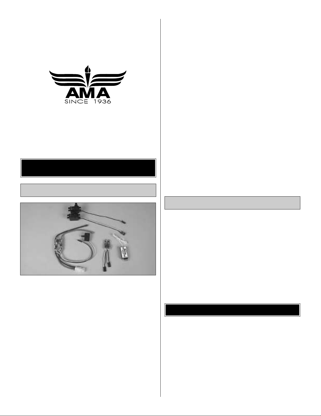
The Slinger requires a three-channel radio with two servos,
a receiver, mixer and a speed control.A small receiver and
mini servos are required, and smaller radio equipment
designed for park flyer models can be used. The servos
must have a minimum of 15 oz-in torque.
Servos:
(HCAM0110) CS-12, 35 oz in torque
(FUTM0033) S3101, 34.7 oz in torque
(HCAM0090) CS-5, 16.7 oz in torque
(FUTM0041) S3106, 16.7 oz in torque
Receivers:
(GPML0044) 4-channel FM, low band
(GPML0045) 4-channel FM, high band
(GPML0056) 5-channel FM, low band
(includes 30 amp ESC)
(GPML0057) 5-channel FM, high band
(includes 30 amp ESC)
(FUTL0442) 4-channel FM, low band
(FUTL0443) 4-channel FM, high band
low band - channels 11-35
high band - channels 36-60
Receiver crystal:
(FUTL62**) for GPM or FUT low band
(FUTL63**) for GPM or FUT high band
** desired channel
Speed Control:
(GPMM2010) C-10, 12 amp
(GPMM2020) C-20, 20 amp
(GPMM2429) Slinger speed control
Mixer:
A mixer (GPMM2428) is required that gives “elevon” or
“ailevator” mixing. Most computer transmitters include this
type of mixer. There are also several mixers available that
plug into the receiver and servos.
Additionally, an 8-cell (9.6 volt) 1100 mAh or larger battery
pack is required.The battery compartment is sized for a 4/5
AA size battery. (GPMP0310) – 1100 mAh Nicd
For charging the battery at the flying field, the Great Planes
ElectriFly™Peak Charger (GPMM3000) is recommended.
The Great Planes ElectriFly Triton™Computerized Charger
(GPMM3150) is recommended for shop and field charging
and discharging.
In addition to common household tools, here is the list of
items used to build the Slinger.
❏ 6-minute epoxy (GPMR6042)
❏ Hobby knife (HCAR0105)
❏ #11 blades (HCAR0211)
❏ Double-sided foam tape (GPMQ4440) for mounting
receiver and speed control
❏ Sandpaper and sanding block
❏ Small Phillips screwdriver (#1)
❏ Small T-pins (HCAR5100) or craft pins
❏ 5/64” drill bit
Since the Slinger is made mostly of foam, and since CA
adhesives commonly used to build R/C model airplanes
dissolve foam, CA should not be used when gluing foam
parts. Therefore, 6-minute epoxy, which is compatible with
foam, is used for construction.Unless otherwise specified in
the instructions, 6-minute epoxy is to be used for gluing all
parts of the model together.
For the strongest bond apply epoxy to both parts being joined.
Photos and sketches are placed before the step they refer
to.Frequently you can study photos in f ollowing steps to get
another view of the same parts.
IMPORTANT BUILDING NOTES
Building Supplies
Flight Equipment
ADDITIONAL ITEMS REQUIRED
3
Page 4
4
Before starting to build, use the Kit Contents list to take an inventory of this kit to make sure it is complete, and inspect
parts to make sure they are of acceptable quality. If any par ts are missing or are not of acceptable quality, or if you need
assistance with assembly, contact Great Planes Product Support. When reporting defective or missing parts, use the
part names exactly as they are written in the Kit Contents list on this page.
Great Planes Product Support
Telephone: (217) 398-8970
Fax: (217) 398-7721
E-mail: productsupport@greatplanes.com
You can also check our web site at www.greatplanes.com for the latest Slinger updates.
KIT CONTENTS
ORDERING REPLACEMENT PARTS
To order replacement parts for the Great Planes Slinger ARF, use the order numbers shown below.Replacement parts are
available only as listed.Not all par ts are available separately. Replacement par ts are not available from Product Support,
but can be purchased from hobby shops or mail order/Internet order firms. Hardware items (screws, nuts, bolts) are also
available from these outlets. If you need assistance locating a dealer to purchase parts, visit and click on “Where to Buy”.
If this kit is missing parts, contact Great Planes Product Support.
Part # Description How to Purchase
GPMA2423 ......WING SET ....................Contact Your Hobby Dealer
GPMA2424 ......Center wing cover......Contact Your Hobby Dealer
GPMA2425 ......W
ING TIPS....................Contact Your Hobby Dealer
GPMA2426 ......W
ING JOINERS (2) ........Contact Y our Hobby Dealer
GPMA2427 ......380
MOTOR ..................Contact Your Hobby Dealer
GPMA2428 ......F
LAPERON MIXER ..........Contact Y our Hobby Dealer
GPMA2429 ......S
PEED CONTROL...........Contact Y our Hobby Dealer
Part # Description How to Purchase
GPMA2430 ......DECAL SET...................Contact Y our Hobby Dealer
GPMA2431 ......B
ATTERY PACK ..............Contact Y our Hobby Dealer
GPMA2432 ......C
ANOPY.......................Contact Y our Hobby Dealer
GPMA2433 ......P
ROPELLER ..................Contact Y our Hobby Dealer
Missing pieces ...........Contact Product Suppor t
Instruction manual .....Contact Product Support
Full-size plans............Not available
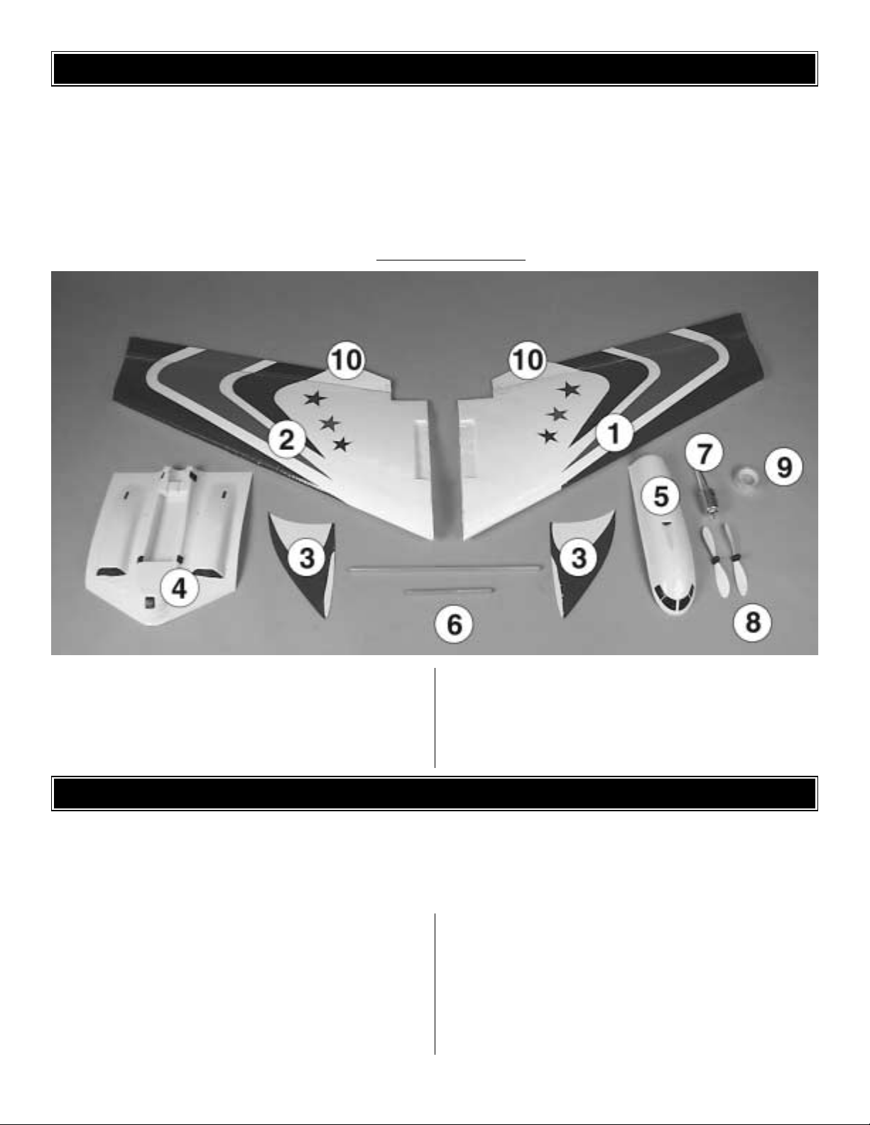
Kit Contents (Photographed)
1. Left Wing Panel 6.Wing Joiner Tubes
2. Right Wing Panel 7. Motor
3.Wing Tips (2) 8. Propellers
4. Plastic Center Section 9.Tape
5. Plastic Canopy 10. Ailevators
Kit Contents (Not Photographed)
Nylon Control Horns (2) 2-56 x 1/2” Machine Screw (4)
12” Pushrods (2) Nylon Clevis (2)
Nylon Tie Strap (1) Silicone Retainer (2)
Hook and Loop Tape (1)
Page 5

❏ 1. Apply the decals to the front of the dummy engine
inlets on the plastic center section. Also, apply the
windshield decals to the canopy. Install the Velcro®tape
where shown above on the plastic center section and on the
inside of the canopy (battery cover).
❏ 2. Make any needed cutouts in the center section for the
motor strap, pushrod exits, receiver antenna and servo
wires where shown in the photo above.
Caution:The best tool for this is a Dremel®type high speed
tool with a 1/8” carbide cutter.If you use a model knife with
a #11 blade, use extreme care not to cut yourself.
❏ 3. Secure the motor to the center section with the
included nylon tie strap. Notice that the wires have already
been soldered to the motor.
Start with the left wing panel so that your progress will
match the following photos.
❏❏1. Find the cutout in the wing, under the plastic film
covering, for the servo. Remove the covering from over the
cutout.Your servo should fit tightly into the cutout. If it does not
fit tightly, or if you are using a smaller servo, glue some scrap
foam or balsa shims (not included) into the cutout as needed.
❏❏2. Remove the screw from the servo holding the servo
control arm in place and remove the arm as well. Trim the
arm so that there is only one arm remaining.
❏❏3. Plug the servo into the proper receiver channel (or
mixer if used.See the photo on page 7.) Center the trims on
the transmitter and then turn on the transmitter. Plug the
ESC into the receiver and connect a charged battery to the
ESC. Turn on the receiver according to the instructions
supplied with the ESC.With the controls in neutral, reinstall
the servo control arm and screw. The arm should be
perpendicular to the servo. Turn off the receiver and
transmitter and unplug the servo.
❏❏4. Insert the ser vo in the cutout. The servo should be
even with the top of the wing.If it isn't, deepen the cutout
as required.Use clear tape to hold the servo in the wing.An
unused clear part of the decal sheet may also be used.
❏ 5. Return to step one and install the other ser vo.
Install the Servos
Assemble the Center Section
ASSEMBLY
5
Page 6

❏❏1. Install a control horn on the top of the ailevator with
two 2-56 x 3/8” [9.5mm] screws and the nylon backplate.
The control horn should be in line with the servo arm as
shown in Step 2.Drill 5/64” [2mm] holes for the scre ws.Note
that the holes in the front of the control horn (for the clevis)
are in line with the hinge line.
❏❏2.Thread a nylon clevis twelve turns onto a 12”[305mm]
pushrod. Install a silicone retainer on the clevis. Connect the
clevis to the second hole from the top on the control horn.With
the servo and ailevator centered, mark the pushrod where it
meets the outer hole in the servo arm. Make a Z-bend in the
pushrod at the mark.If necessary, enlarge the hole in the servo
arm with a #48 drill bit (or a 5/64” [2mm] drill). Remove the
pushrod from the control horn and insert the Z-bend into the
servo arm. Connect the clevis to the control horn.
Note: See page 8, Step 2 for an explanation of centering
the ailevators.
❏ 3. Return to step one for the other wing panel.
❏ 1. Insert the aluminum joiner tubes into the left wing
panel.The longer tube goes in the rear hole.
❏ 2. Join the right wing panel onto the joiner tubes in the
left panel. Use the white tape on the bottom of the wing to
hold the wing panels together.
Join the WingsInstall the Ailevators
6
Page 7

❏ 1. Remove the pushrods from the control horns. Insert
the pushrods through the holes in the center section. Route
the servo wires through their respective holes. Position the
center section onto the wing and check that the hole for the
receiver antenna is aligned with the antenna tube in the left
wing panel.Adjust the hole in the center section as needed.
❏ 2. Attach the center section to the wing with clear tape.
Tape all of the edges securely.
Caution: The center section must be securely taped to the
center section. It contains the heavy battery and motor.The
center section also generates considerable lift in flight.
❏ 3. Plug the ailevator servos into the optional mixer
(if used) as shown in the photo. Note the aileron and
elevator plugs that go to the receiver. You may need to
reverse the plugs to the receiver if the ailevators do not
respond correctly. The elevator stick should move both
ailevators in the same direction while the aileron stick
should move them in opposite directions.
❏ 4. Plug the motor wires into the ESC and plug the ESC
into the receiver. Plug the servos into the proper receiver
channel (or mixer if used). Insert the receiver antenna into
the antenna tube in the top of the left wing panel until it
comes out the other end. In the above photo the mixer is
held to the receiver with double-sided foam tape. The
receiver is held in the receiver compartment, also with
double-sided tape.The ESC will go on the top of the battery
after it is placed in the battery compar tment.
❏1. Apply the decals onto the wing tips as shown in the photo.
Position the wing tip onto the wing panel and mark the tip where
it meets the wing. Cut and remove the decal from the wing tip
about 1/16” [1.6mm] inside the marks you made. Roughen the
exposed surface with sandpaper. Warning: The wing tip is
glued to the wing.Failure to remove the decal material from the
mating surface of the tip may allow the tip to separate in flight.
Note:The wing tips should extend below the bottom of the wing
enough so that the ailevators do not snag on the tips when the
ailevators are down. See the photo that follows.
❏ 2. Glue the wing tips to the wing with 6-minute epoxy.
Install the Wing Tips
Install the Center Section
7
Page 8

❏1.Install the battery in the battery compartment.The supplied
strip of Velcro tape can be used to hold the battery in place.
❏ 2. Fit the canopy (battery cover) to the center section. The
ESC can be held to the top of the battery with some V elcro tape.
❏3.The prop has a raised flat area at the center of the prop on
one side.This is the front of the prop, which must face the front
of the model when the prop is installed on the motor.Install the
spinner hub on the prop as shown in the above photo.
❏ 4. Install the prop on the motor. Make sure the prop is
clear of any obstacles.Tur n on the transmitter and receiver.
Slowly advance the throttle and make sure the prop turns in
the proper direction. If not, reverse the wires to the motor.
IMPORTANT: Read the note that follows.
Note:If you are using the optional ESC be sure to follow this
arming procedure:
1.Turn on the transmitter and move the throttle to idle power.
2.Turn on the switch for the ESC.
3.Wait one second, then advance the throttle to full power.
4.Wait one second, then move the throttle to idle power.
5.The ESC is now ar med. Moving the throttle to a higher
power setting will cause the propeller to rotate.
❏ 5. Apply the decals to the model as desired. Use the box
cover as a guide in applying any decals.You can also use
colored felt tip marking pens to color areas of the model
without adding any weight.
IMPORTANT: Whenever connecting the battery always
hold on to the fuselage incase the motor accidentally
receives power and the propeller turns.
❏ 1. Turn on the transmitter, connect the battery to the
speed control and turn on the receiver. Be certain the
ailevators and motor respond as shown in the chart. If
required, use the reversing function in the transmitter to
reverse any controls necessary so they respond correctly.
❏ 2. Check the ailevators to see if they are centered.Use a
straightedge to align the bottom of the ailevators with the
bottom of the wing as shown above .If necessary , adjust the
clevises on the pushrods to center the ailevators.
NOTE: Unless you are specifically checking the operation
of the motor, for safety remove the propeller from the
model while setting it up on your workbench.
Set the Control Throws
PREPARE THE MODEL FOR FLYING
Final Assembly
8
Page 9

❏ 3. Use the ATV function in the transmitter or adjust the
position of the pushrods on the servo arms and the control
horns on the ailevators to get the control surface throws
shown in the chart that follows.The throws are measured at
the widest part of the control surface.
To increase the control surface throw, move the pushrod to
the hole that is farther in on the control horn on the control
surface, or move the pushrod to the hole that is farther out
on the servo arm.To decrease the control surface throw, do
the opposite.
The recommended control throws for the Slinger require
that the ailevators ha v e more thro w f or aileron tr a v el than for
elevator travel. If your radio transmitter does not have
Adjustable Travel Volume (ATV) or Dual Rates (D/R), which
will enable you to set the recommended throws, you should
carefully consider how to proceed. ATV will allow you to
reduce the elevator throw while keeping a higher aileron
throw .D/R normally is used to set reduced throws, but many
transmitters also allow this function to set increased throws
as well. This would allow you to increase the aileron throw
while keeping a lower elevator throw.
If you are using a very basic radio that does not allow
you to independently adjust the elevator and aileron
travel, you should set both throws to 1/2”[12.7mm].
We do not recommend that you set the ele vator tr av el higher
than 1/2” [12.7mm] on high rate as doing so could cause the
Slinger to snap roll at unexpected times.Without the ATV or
D/R functions, this will restrict the aileron throw to 1/2”
[12.7mm] as well. Sacrificing some aileron authority is
preferable to having too much elevator sensitivity.
The C.G.(center of gravity) must be checked when the model
is ready to fly with the propeller, canopy and battery installed.
❏ 1. Use a felt-tip pen or narrow strips of tape to mark the
balance point on the top of the wing 8” [203mm] from the
forward most part of the model.
❏ 2. Lift the model, upside down, at the balance point you
marked on the top of the wing. In the photo, we are using a
Great Planes CG Machine™. If the nose drops the model is
nose-heavy and you must add weight to the tail. If the tail
drops, the model is tail-heavy and you must add weight to the
nose. In most cases you can relocate the receiver to achieve
the correct balance without adding more weight.
IMPORTANT: More than any other factor, the C.G. (balance
point) can have the greatest effect on how the model flies,
and may determine whether or not your first flight will be
successful. If you value this model, DO NOT OVERLOOK
THIS IMPORTANT PROCEDURE. A model that is not
properly balanced will be unstable and possibly unflyable.
Balance the Model (C.G.)
Set up the Slinger so it has the following control
surface throws:
High Rate Low Rate
ELEVATOR: 1/2" [13mm] 3/8" [10mm]
up and down up and down
AILERONS: 3/4" [19mm] 1/2" [13mm]
up and down up and down
Second to the C.G., the control throws have the greatest
effect on the way a model flies. Set the throws as close to
these settings as possible. If you have too much control
throw the model may respond too quickly.If you do not have
enough throw you may not be able to maneuver the model
or have enough control to land it when the motor is off.
Caution: With more than 1/2" [12.7mm] elevator throw,
the Slinger may snap roll unexpectedly during
aerobatic maneuvers.
9
Page 10

❏ 3. If additional weight is required to balance the model,
use small pieces of Great Planes stick-on weight
(GPMQ4485).If weight is required in the tail, it can be stuck
to the top of the wing next to the motor. If weight is required
in the nose, a slot can be cut in the nose where the weight
can be inserted.The slot can then be covered with tape.Our
prototype model required 1 oz. of weight on the nose.
❏ 4. After placing weight on the model where necessary,
recheck the C.G.to confir m that it is correct.
No matter if you fly at an AMA sanctioned R/C club site or if
you fly somewhere on your own, you should always have
your name, address, telephone number and AMA number
on or inside your model. It is required at all AMA R/C club
flying sites and AMA sanctioned flying events. Photocopy
and fill out the identification tag on the last page and place
it on or inside your model.
Be certain the transmitter batteries are fully charged. Follow
the battery charging instructions that came with your radio
control system to charge the batteries.
Before you fly y ou should perform one last ov erall inspection to
make sure the model is truly ready to fly and that you haven’t
overlooked anything.If you are not thoroughly familiar with the
operation of R/C models, ask an experienced modeler to
perform the inspection. Check to see that you have the radio
installed correctly and that all the controls are connected
properly. The motor must also be checked by confirming that
the prop is rotating in the correct direction and the motor
sounds like it is reaching full power .Make certain the ailevators
are secure, the pushrods are connected, the controls respond
in the correct direction, radio components are securely
mounted, and the C.G.is correct.
Ground check the operational range of your r adio before the
first flight of the day. With the transmitter antenna collapsed
and the receiver and transmitter on, you should be able to
walk at least 100 feet away from the model and still have
control. Have an assistant stand by your model and, while
you work the controls, tell you what the control surfaces are
doing. Repeat this test with the motor running at various
speeds with an assistant holding the model, using hand
signals to show you what is happening. If the control
surfaces do not respond correctly, do not fly! Find and
correct the problem first. Look for loose servo connections
or broken wires, corroded wires on old servo connectors,
poor solder joints in your battery pack or a defective cell, or
a damaged receiver crystal from a previous crash.
Use fine sandpaper to remove imperfections along the
edges of the propeller.For the best performance, use a Top
Flite Precision Magnetic Prop Balancer™ (TOPQ5700) to
balance the propellers (this is a necessity on glow-powered
engines, and should be done with electric models as well).
Using multiple battery packs for successive flights may
cause the motor to become excessively hot, thus causing
damage. Allow the motor to cool for at least 10 minutes
between flights.
Failure to follow these safety precautions may result in
severe injury to yourself and others.
Get help from an experienced pilot when learning to
operate motors.
Use safety glasses when running motors.
Do not run the motor in an area of loose gravel or sand;the
propeller may throw such material in your face or eyes.
Keep your face and body as well as all spectators away from
the path of the propeller as you start and run the motor.
Keep items such as these away from the prop: loose
clothing, shirt sleeves, ties, scarfs, long hair or loose objects
(pencils, screw drivers) that may fall out of shirt or jacket
pockets into the prop.
Motor Safety Precautions
Perf ormance Tips
Range Check
Ground Inspection
Charge the Transmitter Batteries
Identify your Model
10
Page 11

The electric motor and motor battery used in the Slinger are
very powerful and the spinning propeller has a lot of
momentum; therefore, if you touch the propeller while it is
spinning it may inflict severe injury. Respect the motor and
propeller for the damage they are capable of and take
whatever precautions are necessary to avoid injury. Always
disconnect and remove the motor battery until you are
ready to fly again and always make sure the switches are
turned off before connecting the battery.
Read and abide by the following Academy of Model
Aeronautics Official Safety Code:
GENERAL
1. I will not fly my model aircraft in competition or in the
presence of spectators until it has been proven to be airworthy
by having been previously successfully flight tested.
2. I will not fly my model aircraft higher than approximately
400 feet within 3 miles of an airport without notifying the
airpor t operator. I will give right of way to and avoid flying in
the proximity of full scale aircraft. Where necessary, an
observer shall be utilized to supervise flying to avoid having
models fly in the proximity of full-scale aircraft.
3.Where established, I will abide by the safety rules for the
flying site I use and I will not willfully and deliberately fly my
models in a careless, reckless and/or dangerous manner.
7. I will not fly my model unless it is identified with m y name
and address or AMA number, on or in the model.
RADIO CONTROL
1. I will have completed a successful radio equipment ground
check before the first flight of a new or repaired model.
2. I will not fly my model aircraft in the presence of
spectators until I become a qualified flyer, unless assisted
by an experienced helper.
3.I will perform my initial turn after takeoff away from the pit,
spectator and parking areas and I will not thereafter
perform maneuvers, flights of any sort or landing
approaches over a pit, spectator or parking area.
4. I will operate my model using only radio control
frequencies currently allowed by the Federal
Communications Commission.
Though the Slinger is a “Park Flyer,” the best place to fly any
model is at an AMA chartered club field. Club fields are set up
for R/C flying, making your outing safer and more enjoyable.
We recommend that you join the AMA and a local club so you
can have a saf e place to fly and ha v e insurance to co v er you in
case of a flying accident. The AMA address and telephone
number are in the front of this manual.
If there is no club or R/C flying field in your area, find a
suitable site that is clear of trees, telephone poles,
buildings, towers, busy streets and other obstacles. Since
you are not flying at a sanctioned AMA site, be aware that
there may be others like yourself who could be flying
nearby. If both of your models happen to be on the same
frequency, interference will likely cause one or both of the
models to crash.An acceptable minimum distance between
flying models is five miles, so keep this in mind when
searching for a flying site.
In addition to obstacles, it is important to be aware of
people who may wander into the area once you begin
flying. At AMA club flying sites it is a severe rule infraction
to fly over others, and this is a good practice if flying
elsewhere. R/C models tend to attract onlookers whose
numbers can soon multiply, forming small, uncontrolled
crowds. Onlookers pose two main problems. First is the
danger of actually crashing your model into a person,
causing injury .Second is the distraction from those who ask
you questions while you are trying to concentrate on flying.
To minimize or avoid this problem, have an assistant
standing by who can spot people who wander into your
flying site (so you can avoid flying over them) and who can
perform “crowd control” if people start to gather.
IMPORTANT: If you are an inexperienced modeler we
strongly urge you to seek the assistance of a competent,
experienced R/C pilot to check your model f or airw orthiness
AND to teach you how to fly. No matter how stable or
“forgiving” the Slinger is, attempting to learn to fly on your
own is dangerous and may result in destruction of your
model or even injury to yourself and others.Therefore, find
an instructor and fly only under his or her guidance and
supervision until you have acquired the skills necessary for
safe and fully controlled operation of your model.
Takeoff
We recommend flying the Slinger when the wind is no
greater than ten miles per hour. Less experienced flyers
should fly the Slinger only in calm (less than one mile per
hour) conditions. Frequently, winds are calm in the early
morning and early evening. Often these are the most
enjoyable times to fly anyway!
FLYING
FIND A SAFE PLACE TO FLY
AMA SAFETY CODE (excerpts)
11
Page 12

Until you have the Slinger properly trimmed for level flight,
we recommend having an assistant hand-launch the model
instead of launching it yourself.
Turn on the transmitter and plug the battery into the speed
control. Turn on the receiver by following the instructions that
came with your speed control.Secure the canopy in place.
IMPORTANT: Confirm that the transmitter operates the controls
properly by moving the sticks and watching the surf aces respond.
When ready to launch, the assistant should hold the Slinger
by the leading edges of the wing, with the model in front of
him and pointed into the wind.With the pilot
(that would be
you!)
standing behind the plane, fully advance the throttle to
start the motor. As soon as the motor is at full power, the
hand launcher should gently push the plane into the air at a
level or slightly nose-up attitude. Be certain the model is
being launched into the wind and be immediately ready to
make corrections to keep the airplane flying straight, level
and into the wind.
When the model has gained adequate flying speed under
its own power, gently pull the elevator stick back until the
airplane starts a gradual climb.Many beginners tend to pull
too hard causing the model to stall, so be gentle on the
elevator and don’t panic. If you do pull too hard and you
notice the model losing speed, release the elevator stick
and allow the model to regain airspeed.
Continue a gradual climb and establish a gentle turn (away
from yourself and others) until the airplane reaches an
altitude of 75 to 100 feet.
Flight
The main purpose of the first few flights is to learn how the
model behaves and to adjust the trims for level flight.After the
model has climbed to a safe altitude reduce the throttle slightly
to slow the model, yet maintain altitude.The Slinger should fly
well and maintain adequate airspeed at about 3/4 throttle.
Adjust the elevator trim so the model flies level at the
throttle setting you are using.Adjust the aileron trim to level
the wings. It may take a few minutes to get the trims
adjusted, but this should be your first priority once at a
comfortable altitude.Continue to fly around, executing turns
and making mental notes (or having your assistant take
notes for you) of what additional adjustments or C.G.
changes may be required to fine tune the model so it flies
the way you like.
Landing
Begin the landing approach by flying downwind at an
altitude of approximately 20 feet [6 meters]. When the
airplane is approximately 50 to 100 feet [15 to 30 meters]
past you, gradually reduce power and make the “final” 180degree turn into the wind aligning the airplane with the
runway or landing area. Do not dive the airplane, as it will
pick up too much speed. Instead, allow the airplane to
establish a gradual descent. Concentrate on keeping it
heading into the wind toward the runway. When the plane
reaches an altitude of about 3 feet [1 meter], gently apply a
little “up elevator” to level the plane, but be careful as too
much up elevator will cause it to stall.While holding a slight
amount of up elevator the airplane will slow and descend as
it loses flying speed, thus touching-down on the runway.
Until you are able to accurately judge how far the Slinger can
glide, it may be helpful to reserve some battery power to run
the motor so the plane can be flown back to the runway.
Best of luck and happy flying!
Identification T ag
Use this tag or photocopy it and use the copy.
Please fill in the indicated information and place
the tag in your model.
Printed in China
This model belongs to:
Name
Address
City, State Zip
Phone number
AMA number
 Loading...