

Page 1
WARRANTY
Great Planes
®
Model Manufacturing Co. guarantees this kit to be free from defects in both material and workmanship at the date of
purchase.This warranty does not cover any component parts damaged by use or modification. In no case shall Great Planes’liability
exceed the original cost of the purchased kit. Further, Great Planes reserves the right to change or modify this warranty without notice.
In that Great Planes has no control over the final assembly or material used for final assembly, no liability shall be assumed nor
accepted for any damage resulting from the use by the user of the final user-assemb led product.By the act of using the user-assembled
product, the user accepts all resulting liability.
If the buyer is not prepared to accept the liability associated with the use of this product, the buyer is advised to return this
kit immediately in new and unused condition to the place of purchase.
To make a warranty claim send the defective part or item to Hobby Services at the address below:
Hobby Services
3002 N. Apollo Dr. Suite 1
Champaign IL 61822 USA
Include a letter stating your name, return shipping address, as much contact information as possible (daytime telephone number, fax
number, e-mail address), a detailed description of the problem and a photocopy of the purchase receipt. Upon receipt of the package
the problem will be evaluated as quickly as possible.
READ THROUGH THIS MANUAL BEFORE STARTING
CONSTRUCTION. IT CONTAINS IMPORTANT WARNINGS
AND INSTRUCTIONS CONCERNING THE ASSEMBLY
AND USE OF THIS MODEL.
GPMZ0189 for GPMA1044 V1.0© Copyright 2006
Champaign, Illinois
(217) 398-8970, Ext 5
airsupport@greatplanes.com
INSTRUCTION MANUAL
Wingspan: 82 in [2085 mm]
Wing Area: 1293 sq in [83.4 dm2]
Weight: 13-14.5 lb [5850-6575 g]
Wing Loading: 23-25 oz/sq ft [70-79 g/dm2]
Length: 72 in [1820 mm]
Radio: 4-5 channel transmitter, 6-7 servos
Engine: 1.60-2.00 cu in [26-33 cc] 2-stroke,
1.20-2.00 cu in [20-33 cc] 4-stroke,
2 cu in [32 cc] gas
™
Page 2
INTRODUCTION ...............................................................2
SAFETY PRECAUTIONS..................................................3
DECISIONS YOU MUST MAKE........................................3
Radio Equipment .........................................................3
Engine Recommendations..........................................3
Fuel Tank Setup...........................................................4
ADDITIONAL ITEMS REQUIRED.....................................4
Required Hardware and Accessories..........................4
Optional Supplies and Tools ........................................4
IMPORTANT BUILDING NOTES......................................5
ORDERING REPLACEMENT PARTS ..............................5
KIT CONTENTS ................................................................6
PREPARATIONS ...............................................................7
ASSEMBLE THE WINGS..................................................8
Hinge the Ailerons.......................................................8
Mount the Servos and Hook Up the Ailerons..............9
Mount the Wings .......................................................10
ASSEMBLE THE FUSELAGE.........................................11
Join the Stabilizer and Fin.........................................11
Mount the Servos and Hook Up the Controls...........13
Mount the Tail Gear...................................................13
Mount the Engine and Hook Up the Throttle.............14
Glow Engine
........................................................14
Gas Engine (Fuji-Imvac™BT-32)
.........................15
Mount the Kill Switch (Gas Engines)
..................16
Assemble the Fuel Tank ............................................17
Glow Engines
......................................................17
Gas Engines
.......................................................17
Install the Fuel Tank ..................................................18
Mount the Cowl .........................................................19
FINAL ASSEMBLY..........................................................21
Mount the Main Landing Gear ..................................21
Finish Radio Installation............................................22
Finish the Cockpit and Mount the Canopy................23
Apply the Decals .......................................................24
GET THE MODEL READY TO FLY .................................24
Check the Control Directions ....................................24
Set the Control Throws..............................................24
Balance the Model (C.G.)..........................................25
Balance the Model Laterally ......................................25
PREFLIGHT.....................................................................26
Identify Your Model....................................................26
Charge the Batteries .................................................26
Balance Propellers....................................................26
Ground Check...........................................................26
Range Check.............................................................26
ENGINE SAFETY PRECAUTIONS.................................26
AMA SAFETY CODE......................................................27
IMAA SAFETY CODE.....................................................27
CHECK LIST ...................................................................29
FLYING ............................................................................29
Fuel Mixture Adjustments..........................................29
Takeoff.......................................................................29
Flight..........................................................................30
Landing......................................................................30
TEMPLATES....................................................................31
Thank you for purchasing the Great Planes Giant Super
Sportster ARF. The Super Spor tster is a classic design
that has been around for several years, yet its smooth
lines and gentle curves make it just as popular now as it
was at the start. The Super Sportster is an honest flyer
that is relaxing and enjoyable. Its rugged construction
makes it a practical plane that is easy to handle, so it
should remain in your stable for a long time. Powered by
a 1.60 two-stroke, the Super Sportster handles just like a
hot .60-size plane with the stability and presence of a
giant-scale model. Powered by a Fuji-Imvac 32, the
Sportster flies a little “softer.” The Fuji-Imvac also fits
nicely in the cowl and you can enjoy the economy and
“cleanliness” a gas engine provides. For more on engine
selection read the “Engine Recommendations” section
on the next page.
For the latest technical updates or manual corrections to
the Giant Super Sportster ARF, visit the Great Planes
web site at www.greatplanes.com. Open the “Airplanes”
link, then select the Giant Super Sportster ARF. If there
is new technical information or changes to this model, a
“tech notice” box will appear in the upper left corner of
the page.
We urge you to join the AMA (Academy of Model
Aeronautics) and a local R/C club.The AMA is the governing
body of model aviation and membership is required to fly at
AMA clubs.Though joining the AMA provides many benefits,
one of the primary reasons to join is liability protection.
Coverage is not limited to flying at contests or on the club
field. It even applies to flying at public demonstrations and
air shows. Failure to comply with the Safety Code (excerpts
printed in the back of the manual) may endanger insurance
coverage.Additionally, training prog rams and instructors are
available at AMA club sites to help you get started the right
way. There are over 2,500 AMA chartered clubs across the
country. Contact the AMA at the address or toll-free phone
number below:
Academy of Model Aeronautics
5151 East Memorial Drive
Muncie, IN 47302-9252
Tele. (800) 435-9262
Fax (765) 741-0057
Or via the Internet at:
http://www.modelaircraft.org
IMPORTANT!!!
Two of the most important things you can do to preserve the
radio controlled aircraft hobby are to avoid flying near fullscale aircraft and avoid flying near or o ver groups of people.
AMA
INTRODUCTIONTABLE OF CONTENTS
2
Page 3

1.Your Giant Super Sportster ARF should not be considered
a toy, but rather a sophisticated, working model that
functions very much like a full-size airplane. Because of its
performance capabilities, the Sportster, if not assembled
and operated correctly, could possibly cause injury to
yourself or spectators and damage to property.
2. You must assemble the model according to the
instructions. Do not alter or modify the model, as doing so
may result in an unsafe or unflyable model. In a few cases
the instructions may differ slightly from the photos.In those
instances the written instructions should be considered
as correct.
3.You must take time to build straight, true and strong.
4. You must use an R/C radio system that is in first-class
condition, and a correctly sized engine and components
(fuel tank, wheels, etc.) throughout the building process.
5.You must correctly install all R/C and other components so
that the model operates correctly on the ground and in the air .
6.You must check the operation of the model before every
flight to insure that all equipment is operating and that the
model has remained structurally sound. Be sure to check
clevises or other connectors often and replace them if they
show any signs of wear or fatigue.
7. If you are not an experienced pilot or have not flown this
type of model before, we recommend that you get the
assistance of an experienced pilot in your R/C club for your
first flights.If you’re not a member of a club, your local hobb y
shop has information about clubs in your area whose
membership includes experienced pilots.
8.While this kit has been flight tested to exceed normal use,
if the plane will be used for extremely high stress flying, such
as racing, or if an engine larger than one in the
recommended range is used, the modeler is responsible for
taking steps to reinforce the high stress points and/or
substituting hardware more suitable for the increased stress .
9. WARNING:The cowl and wheel pants included in this kit
are made of fiberglass, the fibers of which may cause eye,
skin and respiratory tract irritation. Never blow into a part
(wheel pant, cowl) to remove fiberglass dust, as the dust will
blow back into your eyes. Always wear safety goggles, a
particle mask and rubber gloves when grinding, drilling and
sanding fiberglass parts. Vacuum the parts and the work
area thoroughly after working with fiberglass parts.
Remember:Take y our time and follow the instructions to
end up with a well-built model that is straight and true.
This is a partial list of items required to finish the Giant
Super Sportster ARF that may require planning or decision
making before starting to build.Order numbers are provided
in parentheses.
Five
medium
torque rating (minimum 50 oz-in [3.9 kg-cm]),
ball bearing servos are required for the elevator, ailerons
and rudder (Futaba®9001 recommended, FUTM0075). One
standard servo is required for the throttle and an additional,
optional standard servo may be used for a throttle-operated
engine kill switch for spark-ignition engines.
In addition to the servos, the following radio equipment will
also be required:
❏ (3) 24" [610 mm] servo extensions f or rudder and elev ator
servos (HCAM2721 for Futaba)
❏ (2) 12" [300 mm] servo extensions for aileron servos
(HCAM2711 for Futaba)
❏ (1) 6" [150 mm] servo extension from receiver for aileron
connection (HCAM2701 for Futaba)
❏ (2) dual servo extensions for aileron and elevator
servos (FUTM4130)
❏ Minimum 1,000 mAh receiver battery (NR4F 4.8V 1,500
mAh NiCd, FUTM1285, or NR4B 4.8V 1,000 mAh NiCd,
FUTM1380)
The recommended engine size range is specified on the cover
of this manual. All engines within the specified range will power
the Giant Sportster well. Never fly your Giant Super Sportster
with an engine larger than one in the specified range because it
has not been designed or tested for larger engines.Powered by
a two-stroke glow engine such as the O.S.®MAX 1.60 FX, the
Sportster performs like a hot .60-size sport plane with the added
stability and durability of any well-designed giant plane.Powered
by the Fuji-Imvac 32, the giant Sportster is a little more “relaxing”
but still plenty capable of all the standard aerobatic maneuvers.
This kit comes with engine mounting posts and the rest of the
mounting hardware for the Fuji-Imv ac 32.If using a different gas
engine, different hardware may be required.
Engine Recommendations
Radio Equipment
DECISIONS YOU MUST MAKE
We, as the kit manuf acturer, provide you with a top quality ,
thoroughly tested kit and instructions, but ultimately the
quality and flyability of your finished model depends on
how you build it; therefore, we cannot in any way
guarantee the performance of your completed model, and
no representations are expressed or implied as to the
performance or safety of your completed model.
PRO TECT YOUR MODEL,YOURSELF
& OTHERS...FOLLOW THESE
IMPORTANT SAFETY PRECAUTIONS
3
Page 4
If you haven’t yet decided whether to use a gas or a glow
engine, some of the things to consider are a gas engine’s
fuel economy–not only is gasoline cheaper than glow fuel,
but gas engines typically burn less fuel as well.Gas engines
are also a little “cleaner” in that they usually put out less
exhaust residue than a glow engine.On the other hand, for
the displacement, glow engines are usually more powerful
than gas engines and are also lighter and smaller.
Here are the order numbers for O.S. MAX and
Fuji-Imvac engines:
❏ O.S.1.60 FX ringed with muffler (OSMG0660)
❏ O.S.1.60 FX ringed without muffler (OSMG0661)
❏ #5010 muffler for O.S. 1.60 FX engine (OSMG2846)
❏ Fuji-Imvac BT-32S R/C gas engine (FJIG0033)
NOTE: If installing a glow engine the following drill bits will
be required:
❏ 13/64" [5.2 mm] (or 3/16" [4.8 mm])
❏ #29 drill and 8-32 tap
OR
❏ Great Planes 8-32 tap and drill set (GPMR8103)
❏ Tap handle (GPMR8120)
If installing a gas engine, a 1/4" [6.4 mm] drill will be required.
If using an O.S.Max 1.60 FX engine, replace the jam nut that
came on the engine with the jam nut included with this kit (that
has a 3/8-24 crankshaft thread).Use the spinner back plate asis without the collared spacer ring and use the included 5 x
35mm spinner bolt to mount the spinner cone. If using an
engine with a different crankshaft thread a spinner adapter kit
from Great Planes or TruTurn will have to be purchased
separately. If a different spinner adapter kit must be used it will
probably require a 10-32 Allen-head spinner bolt, so the
appropriate-length spinner bolt may also have to be purchased.
If using a Fuji 32, the propeller bolt that came with the engine
will have to be replaced by a propeller bolt that is threaded in
the end for a spinner bolt.The TruT urn adapter kit TRUQ4035
may be used, but a 10-32 x 2-1/4" spinner bolt will also have
to be purchased. Or, a special Fuji propeller bolt (FJIG8050)
may also be used and then the 5 x 55 mm spinner bolt
included with this kit will work. In either case, when using the
Fuji engine, the collared spacer ring that came with this kit
will also have to be used in the spinner back plate.
Note: If the appropriate adapter kit or spinner bolt is not
available, a 3-1/4" Great Planes plastic spinner with an
aluminum back plate could be used instead of the included
aluminum spinner. This setup requires no adapter kit
because the cone is mounted to the back plate with four
screws. Order numbers are GPMQ4781 for the red spinner
and GPMQ4780 for the white spinner.
The fuel tank, stopper and hardware included with this kit are
suitable for use with glow fuel. If using a gas engine, the
stopper and fuel line must be replaced with a gas-compatible
stopper and lines and measures must be taken to secure the
fuel lines inside the tank.To do the conversion, the following
items must be purchased separately:
❏ (1) Sullivan #484 Gasoline/Diesel fuel tank conv ersion kit
(SULQ2684)
❏ (2) Packages Du-Bro #813 1/8" [3.2 mm] I.D. fuel line
barbs (DUBQ0670)
❏ At least six small, nylon ties (available from home
improvement, automotive or hardware stores)
❏ Great Planes gasoline fuel tubing (3', GPMQ4135)
OR
#799 3/32" I.D.Tygon Tubing (3', DUBQ0486)
If the Sullivan conversion kit is not available, a Du-Bro #400
gas conversion stopper (DUBQ0675) and one 12" [300 mm]
piece of K+S 1/8" [3.2 mm] soft brass tubing (K+SR5128box of 5) could also be used. Full instr uctions on how to do
the conversion are in the manual.
In addition to the items previously listed in the
“Decisions
You Must Make”
section, following is the list of hardware
and accessories required to assemble the Giant Super
Sportster ARF. Order numbers are provided in parentheses.
❏ Suitable propellers
❏ 3' [900 mm] standard silicone fuel tubing (for glow
engines, GPMQ4131)
❏ R/C foam rubber (1/4" [6 mm], HCAQ1000
OR
1/2" [13
mm], HCAQ1050)
In addition to common household tools and hobby tools,
following are the most important items required to assemble
the Sportster.
❏ 1 oz. [30g] Thin Pro
™
CA (GPMR6002)
❏ 1 oz. [30g] Medium Pro CA+ (GPMR6008)
❏ CA applicator tips (HCAR3780)
Adhesives and Building Supplies
Required Hardware and Accessories
ADDITIONAL ITEMS REQUIRED
Fuel T ank Setup
Spinner Information
Per the IMAA Safety Code, magneto spark-ignition
engines must have a coil-grounding switch to stop the
engine and prevent accidental starting. The switch must
be operated manually (without the use of the transmitter)
and be accessible by the pilot and assistant.For use with
the Fuji-Imvac engine shown, the manually operated
switch was made from a Great Planes Ignition Switch
Harness (GPMG2150) as shown in the manual during the
engine installation process.
4
Page 5
❏ Pro 30-minute epoxy (GPMR6047)
❏ Threadlocker thread locking cement (GPMR6060)
❏ #1 Hobby knife (HCAR0105)
❏ #11 blades (5-pack, HCAR0211)
❏ #11 blades (100-pack, HCAR0311)
❏ Drill bits: 1/16" [1.6 mm], 3/32" [2.4 mm], 1/8" [3.2 mm],
5/32" [4 mm], 3/16" [4.8 mm]
❏ Small, flat metal file
❏ Stick-on segmented lead weights (GPMQ4485)
❏ Silver solder w/flux (GPMR8070)
❏ 21st Century
®
sealing iron (COVR2700)
❏ 21st Century iron cover (COVR2702)
❏ 21st Century trim seal iron (COVR2750)
Here is a list of optional tools mentioned in the manual that
will help you build the Giant Super Sportster ARF.
❏ 2 oz. [57g] spray CA activator (GPMR6035)
❏ Pro 6-minute epoxy (GPMR6045)
❏ R/C-56 canopy glue (JOZR5007)
❏ CA debonder (GPMR6039)
❏ 3M 75 repositionable spray adhesive (MMMR1900)
❏ Epoxy brushes (6, GPMR8060)
❏ Mixing sticks (50, GPMR8055)
❏ Mixing cups (GPMR8056)
❏ Medium T-pins (100, HCAR5150)
❏ Robart Super Stand II (ROBP1402)
❏ Masking tape (TOPR8018)
❏ Wax paper
❏ Denatured alcohol (for epoxy clean up)
❏ Switch & Charge Jack Mounting Set (GPMM1000)
❏ Panel Line Pen (TOPQ2510)
❏ Rotary tool such as Dremel
❏ Rotary tool reinforced cut-off wheel (GPMR8200)
❏ Hobby Heat
™
micro torch (HCAR0750)
❏ Dead Center
™
Engine Mount Hole Locator (GPMR8130)
❏ AccuThrow
™
Deflection Gauge (GPMR2405)
❏ CG Machine
™
(GPMR2400)
❏ Laser incidence meter (GPMR4020)
❏ Precision Magnetic Prop Balancer (TOPQ5700)
❏ Aluminum Fuel Line Plug (GPMQ4166)
• The Giant Super Sportster ARF is factory-covered with Top
Flite®MonoKote®film. The following colors were used and
are available in six foot [1.8m] rolls.If only a small piece of
MonoKote is needed, maybe a modeling friend might have
some in his work shop. Some hobby shops also sell
MonoKote by the foot.
White (TOPQ0204)
Black (TOPQ0208)
True Red (TOPQ0227)
• The stabilizer and wing incidences and engine thrust
angles have been factory-built into this model. However,
some technically minded modelers may wish to check
these measurements anyway.To view this information visit
the web site at www.greatplanes.com and click on
“Technical Data.” Due to manufacturing tolerances which
will have little or no effect on the way your model will fly,
please expect slight deviations between your model and
the published values.
IMPORTANT BUILDING NOTES
Optional Supplies and Tools
5
ORDERING REPLACEMENT PARTS
Replacement parts for the Great Planes Giant Super Sportster
ARF are available using the order numbers in the Replacement
Parts List that follows.The fastest, most economical service can
be provided by your hobby dealer or mail-order company.
To locate a hobby dealer, visit the Hobbico
®
web site at
www.hobbico.com.Choose “Where to Buy”at the bottom of the menu
on the left side of the page.Follow the instructions provided on the page
to locate a U.S., Canadian or International dealer .If a hobby shop is not
available , replacement parts may also be ordered from Tower Hobbies
®
at www.towerhobbies.com, or by calling toll free (800) 637-6050.
Parts may also be ordered directly from Hobby Services by calling
(217) 398-0007, or via facsimile at (217) 398-7721, but full retail prices
and shipping and handling charges will apply. Illinois and Nevada
residents will also be charged sales tax. If ordering via fax, include a
Visa®or MasterCard®number and expiration date for payment. Mai l
parts orders and payments by personal check to Hobby Services
at the address on the front cover of this manual.
Be certain to specify the order number exactly as listed in the
Replacement Parts List. Payment by credit card or personal check
only; no C.O.D.
If additional assistance is required for any reason contact Product
Support by e-mail at:
productsupport@greatplanes.com
(217) 398-8970
Replacement Parts List
Or
der #
Description How to Purchase
Missing pieces Contact Product Support
Instruction manual Contact Product Support
Full-size plans Not available
Contact your hobby supplier to purchase these items:
GPMA2900 .......Wing
GPMA2901 .......Fuselage
GPMA2902 .......Tail Surface Set
GPMA2903 .......Landing Gear
GPMA2904 .......Cowl
GPMA2905 .......Wing Joiner Tube
GPMA2906 .......Canopy
GPMA2907 .......Spinner
GPMA2908 .......Decal Sheet
Page 6
6
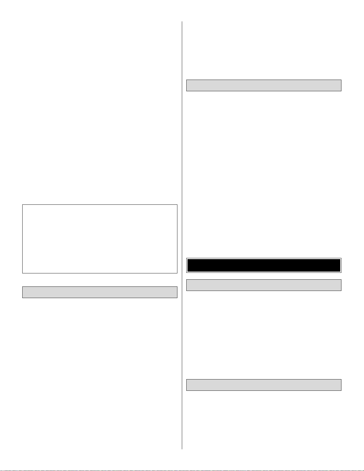
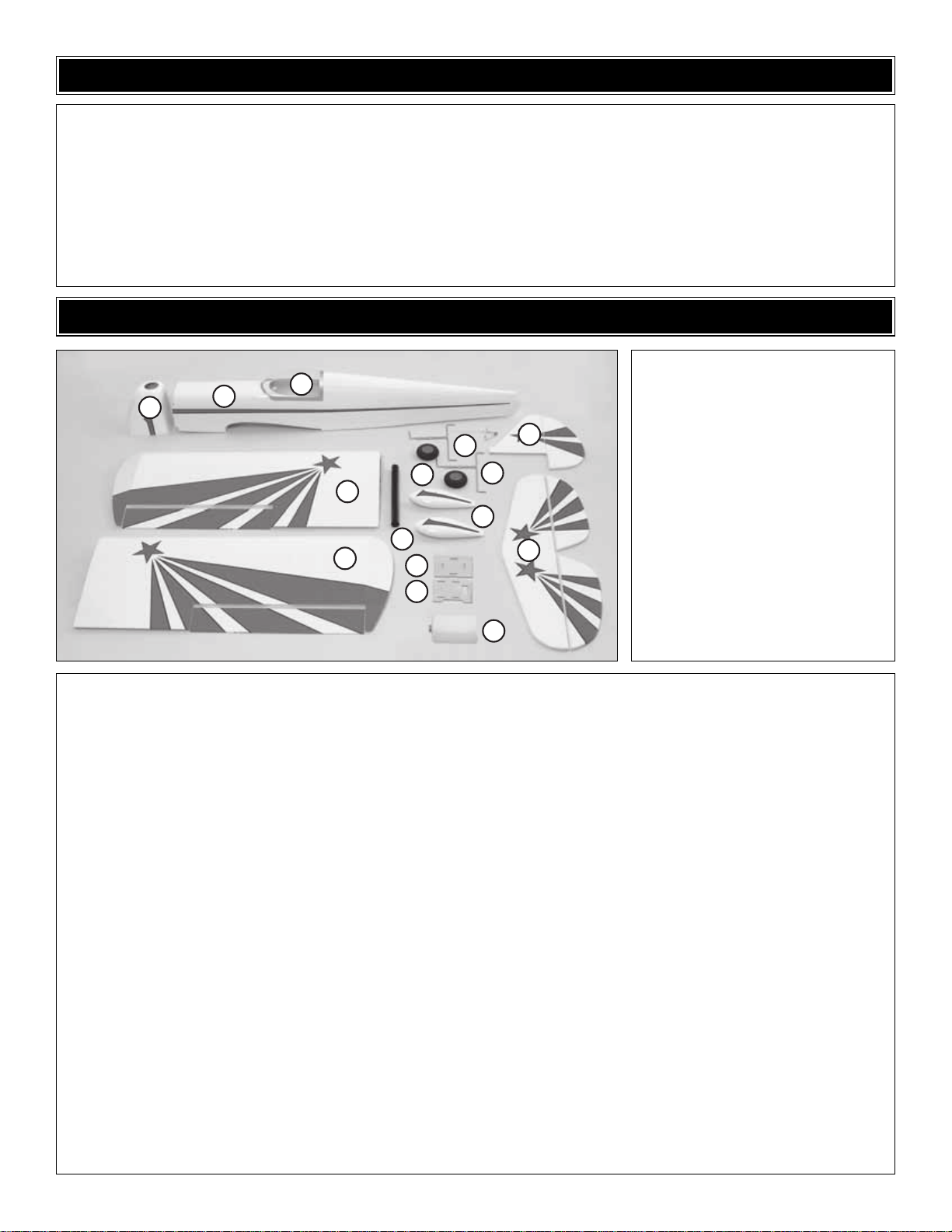
1 Fuselage
2 Cowl
3 Canopy
4 Wing halves w/ailerons (R&L)
5 Hor izontal stabilizer w/elevators
6 Vertical stabilizer (fin) w/rudder
7 (2) wheel pants
8 (2) 3-1/2" [87 mm] main wheels
9 (2) Right and left main landing
gear wires
10 Tail gear wire
11 Aluminum wing joiner tube
12 Battery tray
13 Servo tray
14 Fuel tank w/hardware
Kit Contents (Photographed)
Wood parts:
Plywood ignition kill switch mount set
Plywood pushrod guide tube mounts (2)
10x45 mm wing dowels (2)
6x30 mm antirotation dowel
Cowl mounting blocks for gas engines (2)
Wing bolt plates (2)
Nuts, bolts, washers:
1/4-20x2" [50 mm] nylon wing bolts (2)
8-32x1-1/4" [32 mm] socket head cap screws
(SHCS) (engine mount) (4)
8-32 x 1" [25 mm] SHCS (engine) (4)
#8 flat washers (engine mount) (4)
#8 lock washers (4-engine, 4-engine mount) (8)
8-32 blind nuts (engine mount) (4)
4-40 x 3/4" [19 mm] Phillips screws (control
horns on elevators, rudder) (12)
#4x5/8" [16 mm] Phillips screws (16-main
landing gear straps, 6-cowl, 8-aileron control
horns) (30)
#4 flat washers (cowl) (6)
#4 lock washers (cowl) (6)
4-40 nuts (lock nuts for clevises on pushrods) (5)
2-56 x 3/8" [9.5 mm] Phillips screws (wheel pant
mounting) (8)
#2 x 3/8" [3/8 mm] Phillips screws (tail gear
mounting) (2)
#2 flat washers (wheel pant mount) (8)
2-56 blind nuts (wheel pant mount) (8)
2-56 ball link ball (gas engine throttle) (1)
2-56 lock nut (gas engine throttle) (1)
Brass screw-lock connector (throttle servo) (1)
4-40x1/8" [3.2 mm] SHCS for screw-lock (1)
Nylon retainer for screw-lock (1)
4-40x12" [300 mm] pushrods (2-elevators, 1-
rudder, 2-ailerons) (5)
4-40 metal clevises (2-elevators, 1-rudder, 2-
ailerons) (5)
Large solder clevises (2-elevators, 1-rudder,
2-ailerons) (5)
3/32" [2.4 mm] wheel collar (tail wheel) (1)
4-40 set screw for wheel collar (1)
1" [25 mm] tail wheel (1)
2-56 x 1" [25 mm] threaded rod (for gas throttle
pushrod) (1)
2-56 x 36" [910 mm] pushrod (glow throttle
pushrod) (1)
1/4-20 blind nuts (in fuselage) (2)
Metric fasteners for mounting
Fuji-Imvac 32 engine:
(4) 5x60 mm SHCS
(4) 5 mm lock washers
(4) 5 mm blind nuts
(4) 5 mm wheel collars
(4) 3x5 mm Phillips screw
5x12 mm flat washers (4-engine mounting,
8-wheel spacers) (12)
Hardware:
1.20–1.80 R & L engine mount halves
Aluminum Fuji-Imvac 32 engine spacers (4)
Hump straps (4-wheel pant mount, 2-spares) (6)
24" [610 mm] white, plastic pushrod (for gas
engine) (1)
24" [610 mm] gray throttle pushrod guide tube
(for gas engine) (1)
Giant control horns (5)
Giant control horn mounting plates (1)
Flat landing gear straps (main landing gear
mount) (8)
Nylon ball link (for gas throttle pushrod) (1)
Nylon clevis (for glow throttle pushrod)(1)
Clevis retainers (11)
3/8" [9.5 mm] heatshrink tubing (for servo wires) (1)
CA hinge strips (2)
Velcro
®
strips (2)
Inner, outer fueling line collar (1 glow, 1 gas) (2)
Fuel line plug (2)
Decal sheet
Tail gear assembly:
Tail gear wire
Collar with set screw
Nylon tail gear bearing
Collar w/3mm set screw
Aluminum bracket
Steering post (in rudder)
Spinner assembly:
3-1/4" [83 mm] aluminum spinner
3/8-24 jam nut
Collored spacer ring
5 x 35 mm spinner bolt
5 x 55 mm spinner bolt
5 mm nut
Kit Contents (Not Photographed)
KIT CONTENTS
Before starting to build, take an inventory of this kit to make sure it is complete, and inspect the parts to make sure they
are of acceptable quality. If any parts are missing or are not of acceptable quality , or if y ou need assistance with assemb ly,
contact Product Support. When repor ting defective or missing parts, use the part names exactly as they are written in
the Kit Contents list.
Great Planes Product Support:
3002 N Apollo Drive, Suite 1
Champaign, IL 61822
Telephone: (217) 398-8970, ext. 5, Fax: (217) 398-7721
E-mail: airsupport@greatplanes.com
KIT INSPECTION
2
1
3
10
8
4
7
11
4
12
13
6
9
5
14
Page 7
During construction there will be several occasions where
epoxy cleanup will be necessary. Instead of wasting whole
paper towels, stack three or four paper towels on top of each
other and cut them into small squares. This will conserve
paper towels and the little squares are easier to use. For
epoxy clean up, dampen the squares with denatured alcohol.
❏ 1. Examine the covering on all parts of the airframe.Where
necessary, use a covering iron with a covering sock to remove
any wrinkles. Over sheeted areas, first glide the iron over the
wrinkle until it shrinks. Then, go over the area again, pressing
hard on the iron to thoroughly bond the covering to the wood.
Note: In some areas where the sheeting is thin or unsupported,
less pressure should be used.
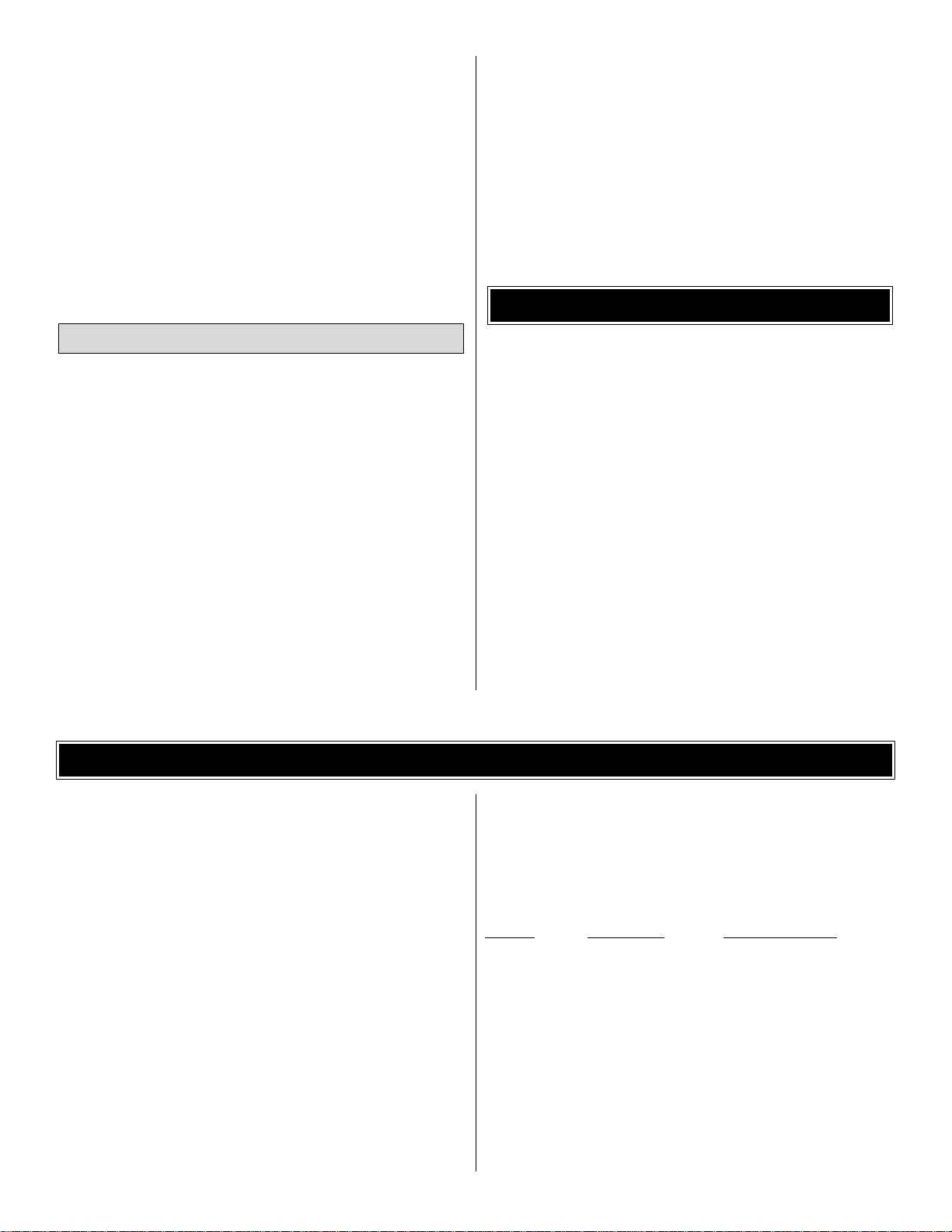
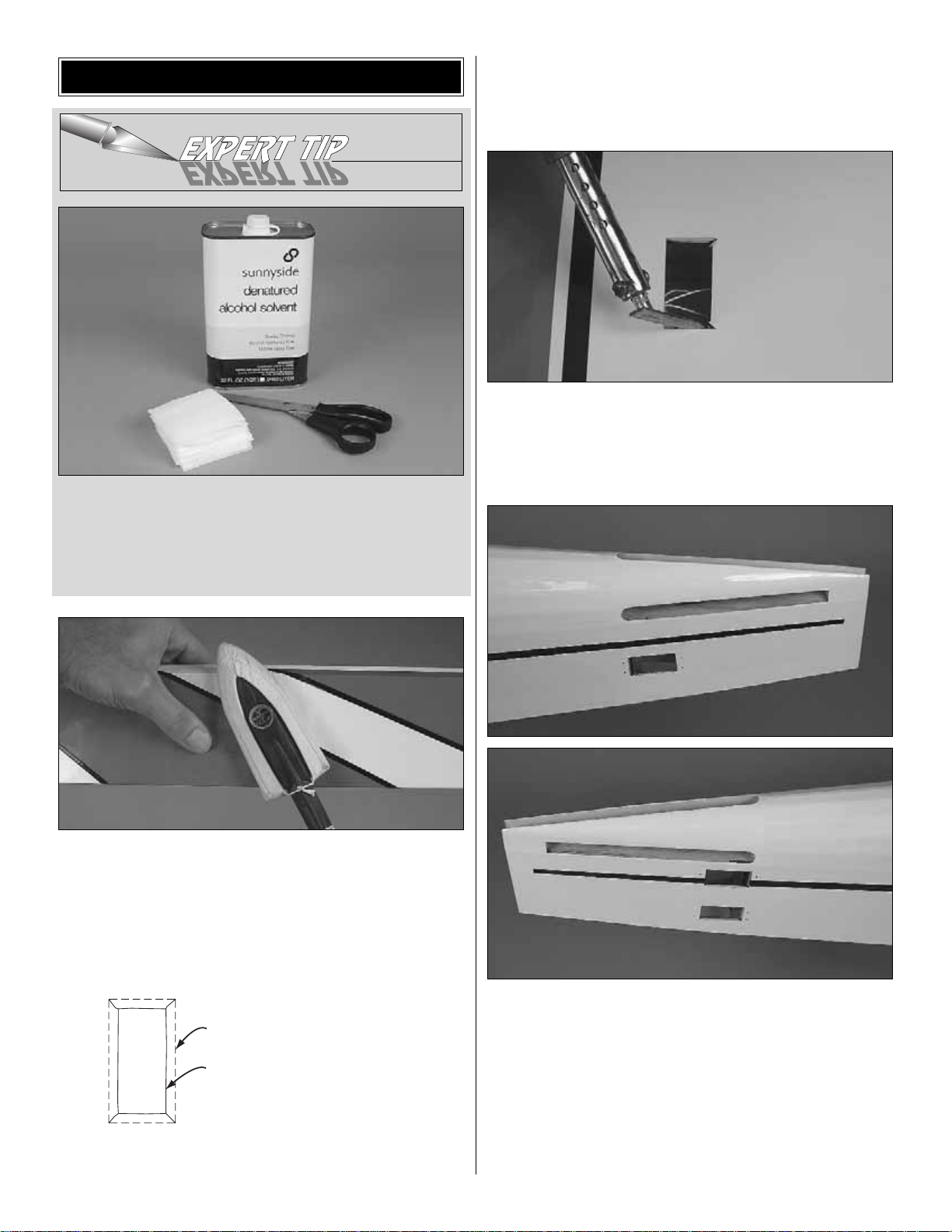
❏ 2.Use a straightedge and a hobby knife to cut the co vering
1/8" [3 mm] inside the openings in the bottom of both wings
for the aileron servos as shown in the sketch. Also cut the
covering from the 1/4" [6.5 mm] wing bolt holes, from the slots
for the main landing gear wires, and from the holes for the
servo wires in the top of both wings near the root ends.
❏ 3. Slit the covering up to the corners of the aileron servo
openings. Use a trim iron to iron the covering down inside
the edges of the servo openings.
Refer to the following photos for Steps 4 and 5.
❏ 4. The same as was done for the ailerons, cut and iron
down the covering from the servo openings in the fuselage.
Also cut the covering from the slots for the stabilizer and fin.
❏ 5. In the fuselage, temporarily place the servos in the servo
openings.Drill 1/16" [1.6 mm] holes for the servo screws.Screw
in all the servo mounting screws that came with the servos.
Remove the screws and servos , and then harden the “threads”
in the holes with a few drops of thin CA in each hole. Set the
servos aside until after the stabilizer has been mounted.
PREPARATIONS
7
SERVO OPENING IN WING
CUT THE COVERING 1/8" [3 mm]
FROM THE EDGES OF THE
OPENING. SLIT THE COVERING
UP TO THE CORNERS.
Page 8
❏ 6. While your trim iron is out, use it to thoroughly seal
the covering around the firewall, around the air passage
cutout at the firewall under the fuselage, and around the
formers at the front and back of the wing saddle.
❏ 7. Mix up a medium-size batch (approximately 1/4 oz
[7.5cc]) of 30-minute epoxy for the following three steps.
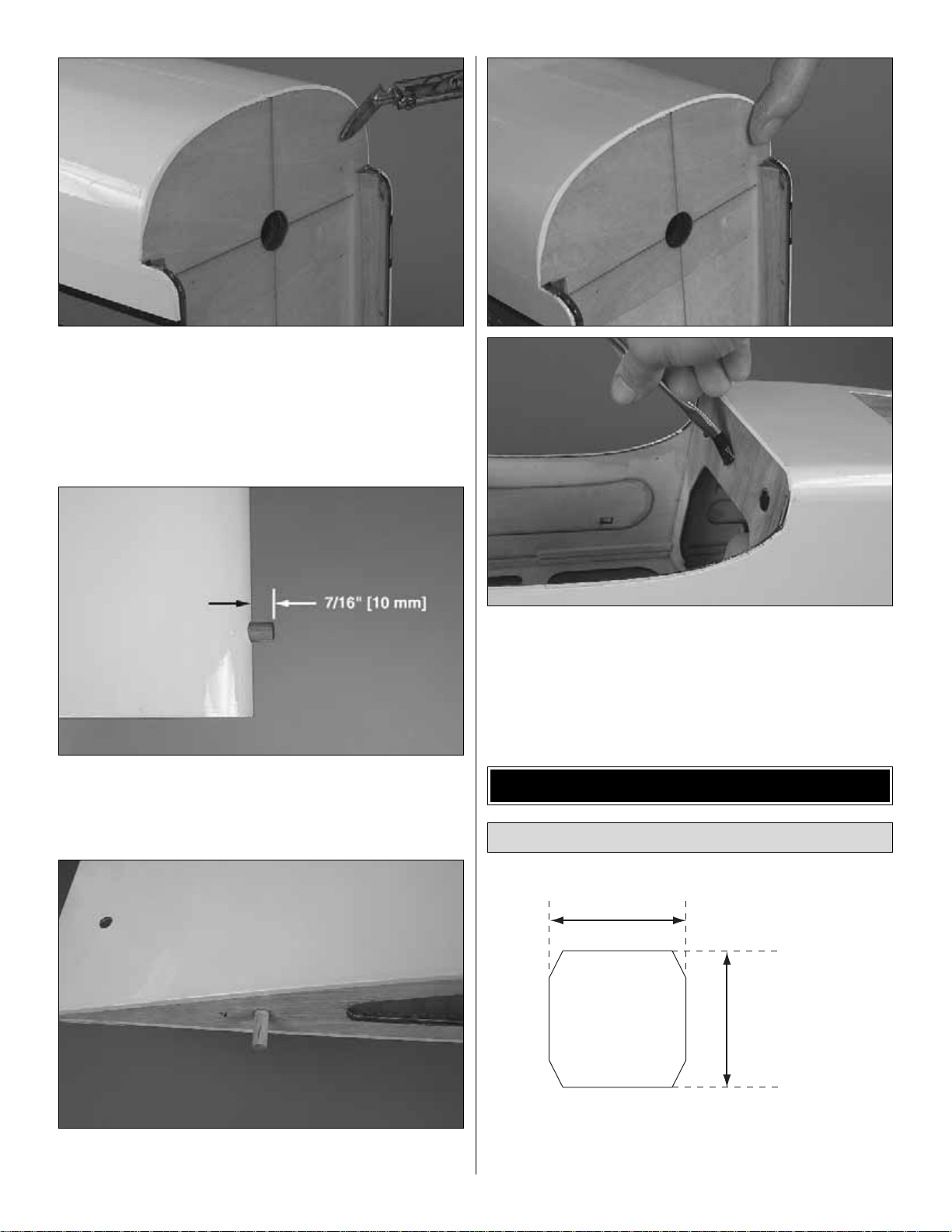
❏ 8.Cut the covering from the holes in the leading edge of both
wing halves for the wing dowels. Chamfer one end of both 3/8"
x 1-3/4" [10 x 45 mm] hardwood wing dowels.Use epoxy to glue
in both dowels so 7/16" [10 mm] of each dowel protrudes.
❏ 9.Use epoxy to glue the 1/4" x 1-1/4" [6 x 30 mm] hardwood
alignment dowel halfway into one of the wing halves.
❏ 10. Spread a thin layer of epoxy over the edges of the
covering around the firewall–this will ensure that the co v ering is
thoroughly sealed and fuel-proofed. Use an epoxy brush to
lightly coat the formers at both ends of the wing saddle as well.
❏ 1. Cut eight 1" x 1" [25 x 25 mm] CA hinges from the
2" x 9" [50 x 230 mm] CA hinge strip. Cut the cor ners off so
the hinges go in easier.
Hinge the Ailerons
ASSEMBLE THE WING
8
1" [25 mm]
1" [25 mm]
Page 9
❏ 2. Stick a T-pin through the middle of all the hinges.Insert
four hinges into the hinge slots of each wing.
❏ 3. Without using any glue, join the ailerons to the wings
and take out the T-pins. Make sure there is a small gap
between the leading edge of each aileron and the wing-just
enough to see light through or to slip a piece of paper through.
❏ 4. Apply at least eight drops of thin CA to the top and
bottom of all the hinges.Allow enough time between each drop
so the CA can soak into the hinge rather than running into the
hinge gap.Hint: CA applicator tips are highly recommended.
Do NOT use accelerator!
❏ 5. After the CA has hardened for a few minutes , pull hard
on each aileron to make sure all the hinges are secure.Add
more CA if necessary.
❏ 1. Connect a 12" [300 mm] servo extension wire to each
aileron servo. Cut one of the pieces of the supplied heat
shrink tubing in half and use each piece to secure each
servo connection.
Refer to this photo while mounting the servos
and hooking up the ailerons.
❏ 2. Use the string in the wings to pull the ser vo wires out
and place the servos in the openings.With the servos in the
wing, drill 1/16" [1.6 mm] holes for all the servo mounting
screws. Temporarily mount the servos with the screws that
came with the servos.
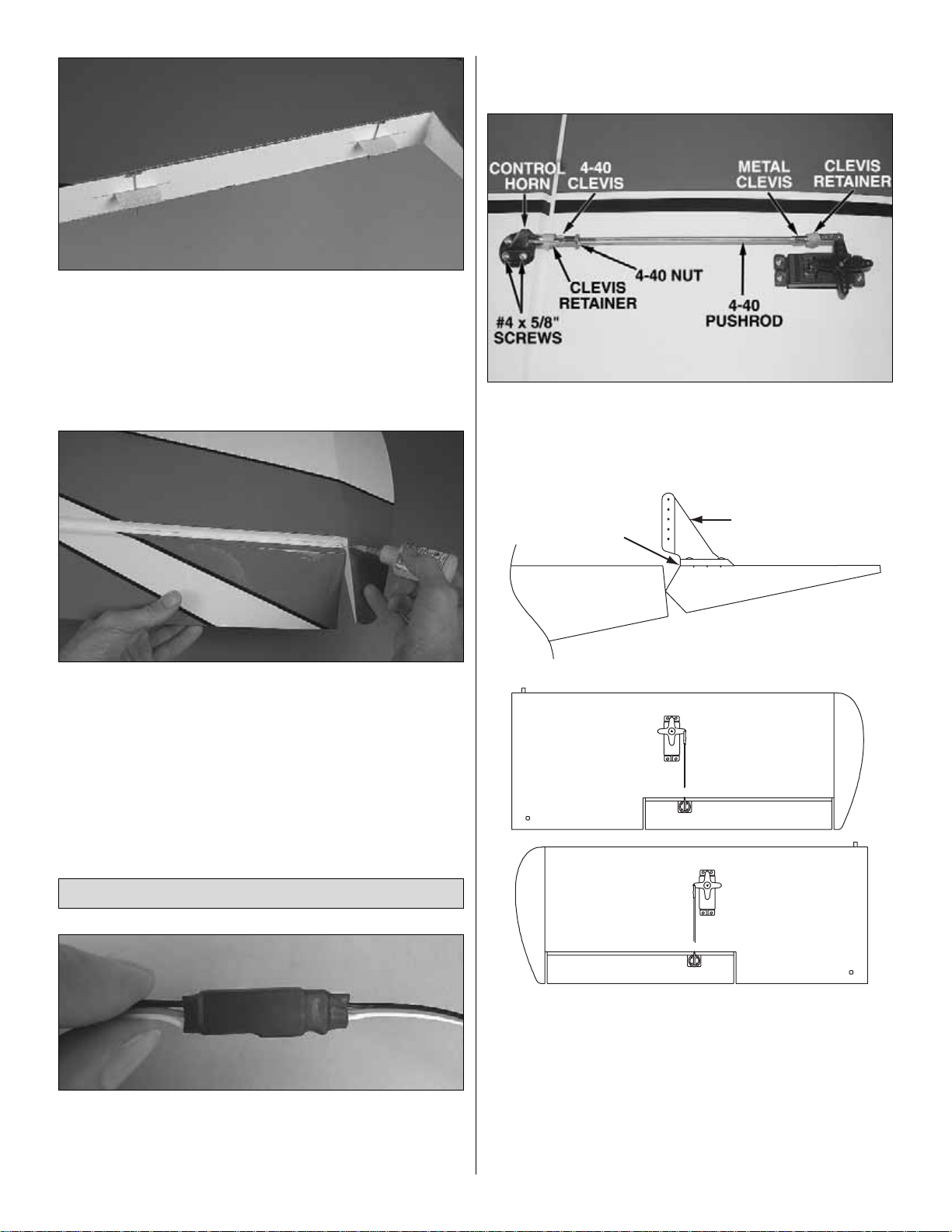
❏ 3. Read the Expert Tip that follows on how to solder.
Connect the aileron servos to the ailerons using the hardware
shown in the photo. The servo arms should be opposed as
shown in the sketches. When mounting the control horns,
place the front of the horn at the front of the aileron as
indicated by the arrow. Drill 3/32" [2.4 mm] holes into the
aileron for the screws.Do not cut the extra arms off the servo
arms until instructed to do so when setting up the radio later.
Note: Screw the 4-40 clevis onto the pushrod twenty full turns.
Mount the Servos & Hook Up the Ailerons
9
CONTROL HORN
Page 10
HOW T O SOLDER
❏ A. Use denatured alcohol or other solvent to thoroughly
clean the pushrod. Roughen the end of the pushrod with
coarse sandpaper where it is to be soldered.
❏ B. Apply a few drops of soldering flux to the end of the
pushrod.Then use a soldering iron or a torch to heat it.“Tin”
the heated area with silver solder (GPMR8070) by applying
the solder to the end. The heat of the pushrod should melt
the solder–not the flame of the torch or soldering iron–thus
allowing the solder to flow. The end of the wire should be
coated with solder all the way around.
❏ C.Place the clevis on the end of the pushrod.Add another
drop of flux.Then, heat and add solder.The same as before,
the heat of the parts being soldered should melt the solder,
thus allowing it to flow .Allow the joint to cool naturally without
disturbing. Avoid excess blobs, but make certain the joint is
thoroughly soldered.The solder should be shiny , not rough.If
necessary, reheat the joint and allow to cool.
❏ D. Immediately after the solder has solidified, but while it
is still hot, use a cloth to quickly wipe off the flux before it
hardens. Important: After the joint cools, coat with oil to
prevent rust.Note: Do not use the acid flux that comes with
silver solder for electrical soldering.
This is what a properly soldered clevis looks like-shiny
solder with good flow, no blobs, flux removed.
❏ 4. Now that the servos and control horns have been
mounted, remove the servo mounting screws and the
control horn screws. Add a few drops of thin CA to each
screw hole to harden the “threads”in the holes. After the CA
has hardened, reinstall all the screws to securely mount the
servos and the horns.
❏ 1. Fit both wing halves together on the joiner tube.Then,
place the wing on the fuselage, keying the dowels into the
dowel holes in the former.
❏ 2.Bolt the wing to the fuselage with two 1/4-20 x 2" [50 mm]
nylon wing bolts and the plywood wing bolt plates underneath.
Use a fine-point felt-tip pen to mark the outline of the wing bolt
plates onto the wing.
❏ 3. Refer to the Expert Tip on page 12.Using care not to cut
into the balsa underneath, use the soldering iron technique or
a sharp #11 blade to cut the covering 1/16" [1.5 mm] inside the
lines you marked around the wing bolt plates.Use one of your
small paper towel squares dampened with denatured alcohol
to wipe away the ink, and then peel off the covering.
❏ 4. If any of the covering has loosened from the sheeting
around the covering you just removed, use a covering iron
with a covering sock to reseal the covering back to the wing.
Use epoxy to glue the wing bolt plates to the bottom of the
wings.This can be done by actually bolting the wings to the
fuselage, but care must be taken not to get excess epoxy
into the wing bolts or on the fuselage-otherwise it could be
difficult to remove the wing after the epoxy has hardened.
Another way to glue the wing bolt plates on is with clamps.
Mount the Wing
10
Page 11

❏ 1. With the wing mounted, temporarily slide the stabilizer
into the fuselage.For now, center the stab as best you can by
eye.Stand approximately ten feet [3 meters] behind the model
and see if the stab aligns horizontally with the wing. If they do
align go to the next step.If the stab and wing do not align, first
try placing a few ounces of weight on the “high side” of the
stab. If that doesn’t do it, remove the stab from the fuselage
and lightly sand the slots in the fuselage to get the stab to
align with the wing. Reinsert the stab and check the
alignment. If necessary, continue to make small adjustments
until alignment is achieved.
❏ 2.Now that the stab aligns with the wing, turn the fuselage
upright. Take accurate measurements to center the trailing
edge of the stab laterally. Inser t T-pins into both sides of the
trailing edge next to the fuselage to hold the alignment.
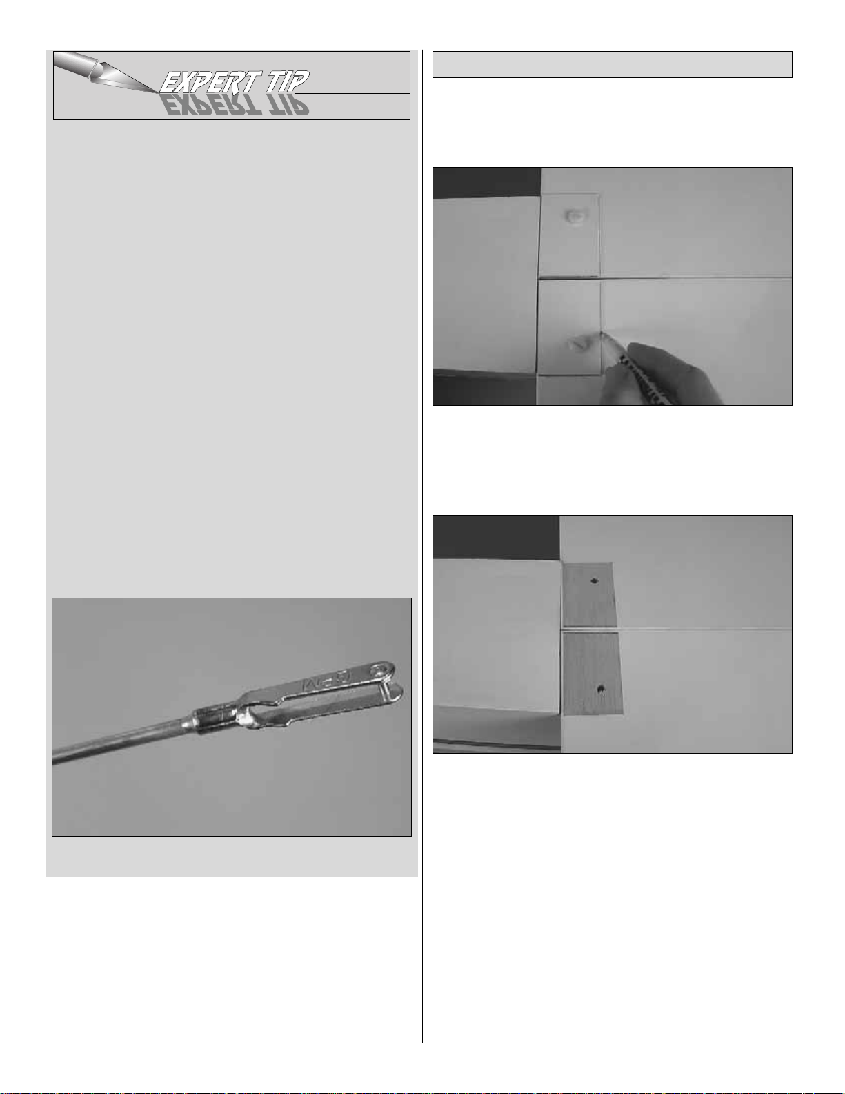
❏ 3. Stick a T-pin into the top of the fuselage centered over the
short center mark on the firewall.Tie a loop in an approximately
60" [150 cm] piece of non-elastic string. Slip the loop in the
string over the T-pin.
❏ 4. Fold a piece of masking tape over the string near the
other end and draw an arrow on it. Slide the tape along the
string and align the arrow with one end of the stab as shown.
Swing the string over to the same position on the other end
of the stab.Rotate the stab about the trailing edge and slide
the tape along the string until the stab is centered and the
arrow aligns with both ends.
A = A'
AA'
Join the Stabilizer and Fin
ASSEMBLE THE FUSELAGE
11
B = B'
B
B'
Page 12

❏ 5. Use a fine-point felt-tip pen to mark the outline of the
fuselage around the top and bottom of both sides of the stab.
❏ 6. Follow the method in the Expert Tip that follows, or
use a sharp hobby blade to cut the covering from the stab
1/16" [2 mm] inside the lines you marked. If using a hobby
blade, use great care not to press too hard and cut into the
wood which will weaken the structure.
HOW TO CUT COVERING FROM BALSA.
To avoid cutting into the balsa, use a soldering iron instead
of a hobby knife to cut the covering.The tip of the soldering
iron doesn’t have to be sharp, but a fine tip does work best.
Allow the iron to heat fully. Use a straightedge to guide the
soldering iron at a rate that will just melt the covering and not
burn into the wood. The hotter the soldering iron, the faster
it must travel to melt a fine cut.
❏ 7. Peel the covering from the middle of the stabilizer .Then
wipe away the ink with a few of your paper towel squares
dampened with denatured alcohol.
Finally! Time to glue in the stab…
❏ 8. Wrap half of the stabilizer with food storage wrap.
Thoroughly coat all joining areas of the stabilizer and fuselage
with 30-minute epoxy. Then, immediately slide the stab into
position. Take the wrapping off the stab. Use paper towel
squares and denatured alcohol to wipe off excess epoxy.
Reinsert the T-pins through the back of the stab on both sides of
the fuselage and use the pin-and-string to permanently center
the stab.Position any weight used to align the stab with the wing.
Do not disturb the model until the epoxy has hardened.
❏ 9. The same as was done for the stabilizer, slide the fin
into position, mark the outline of the fuselage on both sides,
12
Page 13

cut and peel off the covering, and then use 30-minute epoxy
to glue the fin into position. Use a builder’s triangle and if
necessary , pull the top of the fin ov er to one side or the other
of the stab.
❏ 10. After all the epoxy has hardened, join the elev ators to
the stab and the rudder to the fin with the CA hinges and thin
CA. Don’t forget to use T-pins to keep the hinges centered
as you fit the elevators and rudder.
Refer to these photos while mounting the servos.
❏ 1. Connect a 24" [610 mm] servo extension to both elev ator
servos and the rudder servo. The same as with the aileron
servo extensions, secure the connections with the heat shrink
tubing provided with this kit.
❏ 2. Guide the servo wires through the fuselage up into the
radio compartment and mount the servos using the screws
that came with them (the screw holes should have been
previously drilled and hardened).
❏ 3. Make the pushrods and connect the servos to the control
surfaces using the same hardware that was used for the
ailerons-except use 4-40 x 3/4" [19 mm] Phillips screws and
the mounting plates on the other side of the control surfaces
for mounting the horns.When mounting the horns, locate the
clevis holes ov er the pivot point and drill 1/8" [3.2 mm] holes for
the screws through the control surfaces.
Refer to the photo and the sketch to mount the tail gear.
❏ 1.Cut the covering from the 1/4" [6 mm] hole in the bottom
of the fuselage for the nylon tail gear bearing. Glue the
bearing in place with CA. Use care not to get any glue into
the hole in the bearing.
❏ 2. Mount the tail wheel to the tail gear wire with the small
wheel collar and the set screw and mount the tail gear to the
fuselage with the rest of the hardware shown. U se a 1/16"
[1.6 mm] drill to drill the holes in the bottom of the fuselage
for the screws.Don’t forget to install, then remove , the screws
and harden the holes with a few drops of thin CA.Drill a 5/32"
[4 mm] hole into the bottom of the rudder for the steering pin.
Glue the pin in place with CA. Cut off the excess wire.
TAIL GEAR
BEARING
STEERING
POST
ALUMINUM
BRACKET
Mount the Tail Gear
ALIGN THE PUSHROD HOLES
WITH THE PIVO T POINT.
Mount the Servos & Hook Up the Controls
13
Page 14
Follow the instructions for the type of engine you are using.
(Gas-only instructions are shaded)
GLOW ENGINE
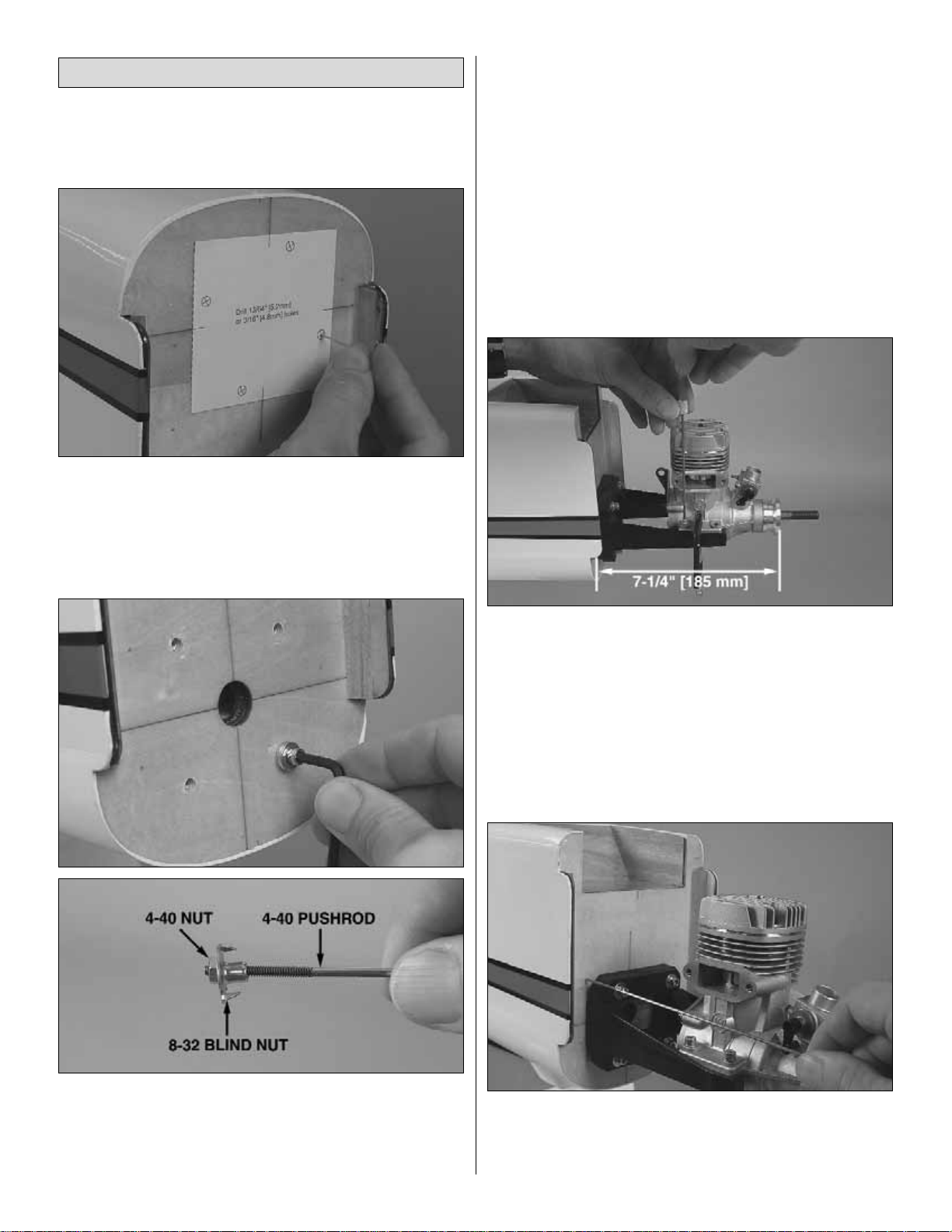
❏ 1. Cut the Glow Engine Mounting Template from the
back of the manual. Use tape or spray adhesive to hold the
template to the firewall with the marks on the template
aligned with the cross marks on the firewall. Use a large
T-pin or a wire sharpened on the end to transfer the bolt hole
marks on the template into the firewall.
❏ 2.Remove the template.Drill 3/32" [2.4 mm] pilot holes at the
marks.Then, enlarge the holes with a 13/64" [5.2 mm] (or 3/16"
[4.8 mm]) drill. Apply a few dabs of epoxy to the front of four
8-32 blind nuts and use an 8-32 x 1" [25 mm] screw with three
#8 washers to draw each blind nut into the back of the firewall.
Hint: If you have difficulty getting the blind nuts started in the
holes, remove one of the aileron pushrods and use it to pull
the blind nuts through with a 4-40 nut.Once the blind nuts are
partially stuck, use the 8-32 screw and washers to draw it the
rest of the way in.
❏ 3. Mount the engine mount to the firewall with four
8-32 x 1-1/4" [32 mm] socket head cap screws (SHCS) and
#8 flat washers and lock washers, but do not tighten the
screws all the way yet.
❏ 4.Place your engine on the engine mount and adjust the
mount to fit the engine. Center the mount from side-to-side
on the screws, then tighten.
❏ 5. Hold the engine to the mount with one or two small
C-clamps so that the front of the drive washer (or the back
plate of the spinner) is 7-1/4" [185 mm] from the firewall.Use
a Great Planes Engine Hole Locator or a drill bit to mark the
engine mounting holes into the engine mounts.
❏ 6. Take the engine off the mount. Drill #29 holes at the
marks. Use an 8-32 tap to cut threads into the holes. Mount
the engine to the mount with four 8-32 x 1" [25 mm] socket
head cap screws and #8 lock washers.
❏ 7. Use a wire shar pened on the end to mark the firewall
where the throttle pushrod will come through to align with
the carburetor arm. Be cer tain the throttle pushrod location
will not interfere with the fuel tank when in position.
Mount the Engine & Hook Up the Throttle
14
Page 15
Refer to the following two photos
while hooking up the throttle.
❏ 8.If necessary, remove the engine.Drill a 3/16" [4.8 mm]
hole through the firewall where you made the mark for the
throttle pushrod.
❏ 9. Cut the 3/16" x 24" [4.8 x 610 mm] gray pushrod tube
to the correct length to be used for the throttle pushrod guide
tube, and then roughen the outside with coarse sandpaper
so glue will adhere. Guide the pushrod tube through the
firewall and the slotted holes on either side of the former that
holds the wing dowels.
Note: A plywood pushrod guide tube
mount is supplied with this kit. If the
throttle does not align with one of the
slotted holes in the former, you could
position the pushrod tube outside the
slots and use the mount to secure the
throttle pushrod tube. Just slip the mount
over the tube and glue it to the former.
❏ 10. Securely glue the plywood servo tray into position so
that the cutout for the throttle servo will be on the same side
as the throttle pushrod. Drop the throttle servo into the tray.
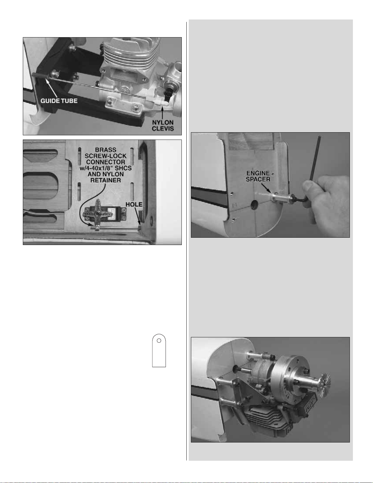
❏ 11. Hook up the throttle using the hardware shown.
Mount the servo to the tray with the screws that came with
the servo. Remove the servo and harden the holes with a
few drops of thin CA, and then remount the servo. Glue in
the throttle pushrod guide tube with CA.
GAS ENGINE (FUJI BT-32)
If mounting a gas engine other than the Fuji BT-32, use
these instructions as a guide for mounting your engine
in a similar manner.
❏ 1. Drill 1/16" [1.6 mm] pilot holes through the firewall at
the four marks for the Fuji Engine.Enlarge the holes with a
1/8" [3.2 mm] drill, followed by a 1/4" [6.4 mm] drill. Note:
The Fuji engine mounting holes are centered over the cross
marks on the firewall. If using a different engine, be sure to
center the engine mount (or the engine) on the cross marks.
❏ 2. Apply a few dabs of epoxy to the front of the four 5mm
blind nuts. Use a 5 x 60mm socket-head cap screw (SHCS)
with a few 5mm washers and one of the aluminum engine
spacers to draw each blind nut into the back of the firewall.
Hint: If you have difficulty getting the blind nuts started in the
holes, remove one of the aileron pushrods and use it to pull
the blind nuts through with a 4-40 nut (as shown for the glow
engine mounting in Step 2 on page 14). Once the blind nuts
are partially stuck, use the 5mm screw, washers and spacer
to draw it the rest of the way in.
❏ 3. Mount the engine with four 5 x 60mm SHCS, 5mm lock
washers and flat washers and the engine spacers.
15
PUSHROD GUIDE
TUBE MOUNT
Page 16

❏ 4. Mount a 2-56 ball link ball to the carburetor arm on the
engine with a 2-56 lock nut. Use a piece of wire shar pened
on the end to mark the firewall where the throttle pushrod
will come through to align with the carburetor arm. Be
certain the throttle pushrod location will not interfere with the
fuel tank when in position.
Refer to the following two photos
while hooking up the throttle.
❏ 5.If necessary, remove the engine.Drill a 3/16" [4.8 mm]
hole through the firewall where you made the mark for the
throttle pushrod.
❏ 6. Cut the 3/16" x 24" [4.8 x 610 mm] gray pushrod tube to
the correct length to be used for the throttle pushrod guide tube.
Then, roughen the outside with coarse sandpaper so glue will
adhere. Guide the tube through the firewall and the slotted
holes on either side of the former that holds the wing dowels.
Note: A plywood pushrod guide tube
mount is supplied with this kit. If the throttle
does not align with one of the slotted holes
in the former, y ou could position the pushrod
tube outside the slots and use the mount to
secure the throttle pushrod tube.Just slip the
mount over the tube and glue it to the f ormer.
❏ 7. Securely glue the plywood servo tray into position so
that the cutout for the throttle servo will be on the same side
as the throttle pushrod. Drop the throttle servo into the tray.
❏ 8.Hook up the throttle using the hardware shown.Mount the
servo to the tray with the screws that came with the servo.
Remove the servo and harden the holes with a fe w drops of thin
CA.Then, remount the servo.Glue in the guide tube with CA.
MOUNT THE KILL SWITCH
(FOR SPARK IGNITION ENGINES ONLY)
As stated in the IMAA Safety Code, all magneto sparkignition engines must have a manually operated, coilgrounding switch to stop the engine and prevent accidental
starting. A home-made switch could be made from a .3 Amp
slide switch, terminals and 16 gauge wire purchased from a
Radio Shack®or other electronic store, or fashioned from a
Great Planes Ignition Switch Harness (GPMG2150). For the
model in the manual, the Great Planes switch was used with
the lever switch removed from the assembly (the servooperated cutoff option was not used). If, in addition to the
required manually operated switch, you would also like a
servo-operated cutoff switch, use a standard servo and
actuate the lever switch via hardware purchased separately.
Refer to this photo while mounting the ignition switch.
❏ 1. Assemble the ignition switch mount from the plywood
parts shown. Fuelproof the mount with fuelproof paint or
epoxy, mount the switch to the mount, and then glue the
mount to the fuselage where it will be easily accessible from
outside the model. (The balsa stick shown in the photo was
used to temporarily hold the switch mount in position while
the epoxy gluing it was hardening.)
❏ 2. Connect the wires to the engine, making certain they
will not contact the engine or muffler.If necessary, the wires
could be wrapped with silicone fuel tubing for insulation.
16
PUSHROD GUIDE
TUBE MOUNT
Page 17

If using a gasoline-powered engine, the fuel tank setup
will have to be converted to work with gas using the
hardware listed in the front of the manual. Follow these
instructions for assembling your fuel tank for the type
of engine you are using.
GLOW ENGINES
❏ 1. Cut two of the aluminum tubes to a length of 1-1/2" [40
mm]. (This can be done by rolling the tubing on your
workbench with a #11 blade.) Assemble the stopper as shown
in the photo.Bend the long tube so it will be at the top of the
tank.Cut the fuel lines to a length that will not allow the clunks
to contact the back of the tank–otherwise they may become
stuck. Note that one of the lines will be used for fueling and
defueling and the other will be the pickup line that goes to the
carburetor. The bent tube will be the vent/pressure line that
will be connected to the pressure tap on the muffler.Proceed
to step 4 to finish assembling the fuel tank.
GAS ENGINES
❏ 1. Cut one of the brass tubes included with the Sullivan
conversion kit in half (two approximately 1-3/4" [45 mm]
pieces).Solder a Du-Bro fuel line barb onto one end of each
of the three tubes.
❏ 2. Assemble the stopper, tubes and metal plates.Solder
another fuel line barb onto the ends of the short tubes. Bend
the brass vent/overflow tube upward so it will be at the top
of the tank.
❏ 3. Connect the fuel tubing to the short tubes and the clunks.
Be certain tubing is cut to a length so that the clunks will not
contact the back of the tank–otherwise they may become
stuck.Note that one of the lines line will be used for fueling and
defueling and the other line will be the pickup line that goes to
the carburetor .The bent tube will be the vent/overflow line that
will be connected to a line that exits the bottom of the fuselage.
Important: Secure both ends of the fuel tubing with small
nylon ties.This is an important measure that must be taken to
be sure the lines remain attached inside the tank.
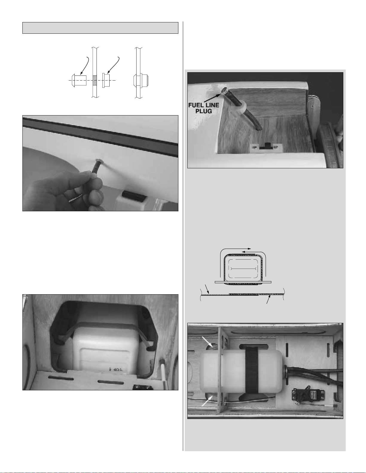
❏ 4. Wr ite “TOP” on the back of the tank so you will know
which way to install it after you have inserted the stopper
assembly. Inser t the stopper so the vent tube will be at the
top of the tank.Then, tighten the screw to squish the stopper
and seal the tank. Shake the tank to make sure the clunks
can move and the fuel lines are not too long. If necessary,
remove the stopper and shorten the lines.
Assemble the Fuel Tank
17
VENT/PRESSURE
(OR OVERFLOW)
One line is for fueling/defueling and
the other is for fuel pickup to the
carburetor (it doesn’t matter which).
Page 18
❏ 1. Determine where you want to locate the fueling line collar
on the side of the fuselage for fueling and defueling the tank.
Use a #11 blade or a drill to cut an 11/32" [8.7 mm] hole at that
location. Note that there are two different inner collars–one with
a smaller I.D. for glow tubing and one with a larger I.D. for gas
tubing. Select the correct inner collar for your application.Then,
from outside the fuselage, fit the inner collar through the hole.
From inside the fuselage, fit the outer collar o ver the inner collar.
Use thin CA to glue the parts together.
If using a gas-powered engine, proceed to step 3.
❏ 2. If using a glow engine, connect the fuel lines to the fuel
tubes coming from the tank.Guide the lines through the hole
in the firewall and place the tank in the forward fuel tank
mounting location behind the firewall. Cut the fuel line that
goes to the carburetor and the vent line that goes to the
pressure tap on the muffler to the correct length, and then
connect them to the engine. Cut the fueling/defueling line to
a length that will allow you to pull the line from the fuselage
through the fueling inlet collar. Guide the line through, and
then insert the plastic fueling plug and press the end of the
line back into the collar. Note: Do not mount the fuel tank in
the aft mounting location for glow engine use. Most glow
engines will not be able to draw fuel from that far away.
Proceed to the next section,
Mount the Cowl.
❏ 3. If using a gas engine, connect the fuel lines to the fuel
tubes coming from the tank.Drill a 1/4" [6.4 mm] hole through
the firewall for the fuel line to the carburetor (the engine will
probably have to be removed to drill the hole) and another
hole for the vent/overflow line so it can be mounted to the
bottom of the fuselage.For the model in the manual, the end
of the vent line was mounted in a hardwood b lock with a 1/4"
hole glued to the bottom of the fuselage. Note: The fuel line
plug should be in place during transportation of the model,
but should be removed during fueling/defueling and flight.
❏ 4. Install the tank in the aft mounting location and hook
up the lines.Hold the tank in position with a #64 rubber band
(indicated by the arrows in the picture) and two opposing 8"
[200 mm] strips of Velcro.
Install the Fuel Tank
18
INNER COLLAR
(GAS OR GLOW)
FUELING LINE COLLAR
OUTER
COLLAR
2. Wrap the Velcro under
the servo tray, around the
“Hook”
side
fuel tank and secure.
1. Cut the Velcro to the
correct length and join
the pieces together.
“Loop”
side
Page 19

(Remember,“Gas-only” steps are shaded.)
❏ 1. This step is necessary only if using a gas engine.
If using a glow engine, proceed to step 2. Use coarse
sandpaper to roughen the firewall for the cowl mounting
blocks. Use 30-minute epoxy to glue both hardwood cowl
mounting blocks into position where shown. (The cowl
blocks are necessary for gas engine installation because the
Fuji 32–and probably most other gas engines–protrude
farther than the 7-1/4" [185 mm] specified for glow engines.
This means the cowl will also be farther forward, so without
the cowl mounting blocks the cowl mounting screws would
be too close to the aft edge of the cowl.)
Refer to this photo for Steps 2 and 3.
❏ 2. Place the cowl on the fuselage over the engine and
temporarily mount the spinner back plate and prop.Align the
front of the cowl with the spinner back plate, with
approximately 1/8" [3 mm] spacing between them. Hint: If
mounting the Fuji 32, temporarily remove the carburetor and
spark plug so the cowl will fit.
❏ 3. Holding the cowl in position, use a fine-point felt-tip
pen to draw the outline of the cowl directly onto the fuselage.
Remove the propeller, back plate and cowl.
Refer to this photo both for Steps 4A and 4B.
❏ 4A. Glow Engines: Using the line around the fuselage
as a reference to take measurements from, drill six 1/8"
[3.2 mm] holes in the sides and top of the cowl so they will
be 3/16" [5 mm] behind the front edge of the firewall–this will
center the screws in the firewall.
❏ 4B.Gas Engines: Using the line around the fuselage as a
reference to take measurements from, drill six 1/8" [3.2 mm]
holes in the sides and top of the cowl. The two top holes
should be positioned so the screws will be centered in the
cowl mounting blocks and the holes in the sides of the cowl
should be approximately 3/8" [10 mm] aft of the front edge of
the side tabs.
❏ 5. Reposition the cowl on the fuselage.Mount the spinner
back plate and prop.
❏ 6. Again holding the cowl in position (it may be helpful to
have an assistant), drill a 3/32" [2.4 mm] hole into the
fuselage through one of the cowl holes. Mount the cowl to
the fuselage with one #4 x 5/8" [16 mm] Phillips screw into
the hole you just drilled.
Perform step 4A only if y ou have mounted a glo w engine.
Perform step 4B only if you have mounted a gas engine.
Mount the Cowl
19
Page 20

❏ 7. Still holding the cowl, drill another hole into the
fuselage through the next cowl screw hole and use another
#4 x 5/8" [16 mm] screw to hold the cowl in place.One at a
time, drill the remaining four holes and mount the cowl with
four more #4 x 5/8" [16 mm] screws.Note: When it’s time to
mount the cowl for flying, use #4 flat washers and #4 lock
washers on the screws.
A Dremel carbide cutter and a
sanding drum are key tools for
cutting out the cowl.
❏ 8. Now that the cowl is mounted, cut any other holes
necessary for engine cooling, head/spark plug clearance,
carburetor access, etc. For the Fuji 32, a template for the
carburetor cutout, air cooling inlet and spark plug clearance
has been provided in the back of the manual. Starting with
the carburetor, cut out the template, and then transfer the
cutout to a piece of thin cardboard or vanilla folder. Align the
cardboard template with the carburetor. Next, tape the
template to the fuselage. Remove the carburetor from the
engine and mount the cowl. Use a fine-point felt-tip pen to
draw the carb cutout onto the cowl.
❏ 9. Remove the cowl and rough-cut the hole. Mount the
carburetor back onto the engine before test-fitting the cowl.
Adjust the cutout as necessary to fit around the carburetor.
❏ 10. Use the spark plug template and the air inlet template
to cut the other holes. If using an engine different than the
Fuji 32, make your own templates and use them to cut the
holes in the cowl the same way.
20
Page 21

❏ 1. File a flat spot in both main landing gear wires where
shown in the photo.
❏ 2. Mount both landing gears to the wings–drill 3/32" [2.4
mm] holes for the #4 x 5/8" [16 mm] screws that hold down
the flat straps.Don’t forget to harden the holes for the scre ws
with thin CA after installing, then removing the screws.
❏ 3. Temporarily place the wheel pants and the wheels on
the landing gear.Then, mount the wings to the fuselage and
set the model on its gear.The end of the “axle”portion of the
gear should key into the hole in the plywood disc on the
other side of the pant.
❏ 4. With the plane sitting on its main wheels and tail
wheel, use a block of balsa or something similar to prop up
one of the wheel pants 5/8" [16 mm].
❏ 5. Fit two mounting straps over the gear. Mark the hole
locations in the straps into the wheel pant–we used our
Great Planes Dead Center™Engine Mount Hole Locator
(GPMR8130) to mark the holes.
❏ 6. Prop up the other wheel pant and mark the strap hole
locations the same way.
❏ 7. Return the plane to your building stand upside-down
and remove the wings. Remove the wheel pants and drill
1/8" [3.2 mm] holes through the pants at each of the marks
for the screw holes in the straps.
Mount the Main Landing Gear
FINAL ASSEMBLY
21
Page 22

❏ 8.Inser t 2-56 blind nuts into each of the four holes in the
wheel pants, drawing them down tight with a 2-56 x 3/8"
[9.5 mm] screw and two washers.Remove the screws, then
glue each blind nut into the pant with two or three drops of
medium CA.
❏ 9. Mount the wheels and pants to the landing gear with
the hardware shown.Be certain to use threadlocker on all the
screws.Use three or four 5mm washers to center the wheels.
If using a gas engine, the model will probably require tail weight
to get it to balance. If using a glow engine, the model will
probably require nose weight to get it to balance. To minimize
any additional nose or tail weight that may be required, mount
the receiver battery in the aft location for gas engines and in one
of the forward locations for glow engines.You could go ahead
and mount the battery and receiver now, or do a quick C.G.
check first to find out where the battery should be mounted. If
you would like to do a quick C.G.check go to page 25.
❏ 1. Use R/C foam and the supplied Velcro strips to mount
the receiver battery.To position the battery as far forward as
possible, mount it to the optional plywood battery tray, and
then securely glue the tray to the balsa rails on both sides of
the fuselage below the fuel tank.(Depending on their size and
configuration, not all batteries will be able to be mounted to
the tray.) If not using the battery tray , mount the battery on the
servo tray next to the throttle servo or to the receiver/battery
tray under the cockpit.
OPTIONAL FORWARD BATTERY
MOUNTING LOCATION
MOUNTING RAILS
BATTERY
TRAY
Finish Radio Installation
22
5 mm WHEEL COLLAR,
3 mm SCREW
WASHERS AS
SPACERS
MOUNTING
STRAPS
2-56x3/8" SCREW,
#2 WASHER,
2-56 BLIND NUT
Page 23

❏ 2. Mount the receiver and on/off switch. Connect the
servo wires and switch to the receiver and connect the
battery to the switch.Extend and guide the receiver antenna
through the antenna tube in the fuselage.
❏ 1. The level of detail that may be achieved is up to you.
You could simply glue on the canopy without a pilot, or do a
simple interior by painting it black and adding a pilot, or go
“all out” and mock up a realistic cockpit interior built from
scratch. To finish your model as shown, lightly sand the
cockpit with 400-grit sandpaper, and then paint it black.
❏ 2. Cut out the paper instrument panel from the back of
this manual.Test fit in the cockpit and trim if necessar y.Use
spray adhesive or a glue stick to permanently glue the
instrument panel into position.
❏ 3. Install a pilot of choice. A 1/4 or 1/3-scale pilot is
suitable.The pilot shown is the one included with the Great
Planes Super Stearman ARF and is also available
separately (GPMA2475).Trim down the base of the pilot so
he will fit under the canopy. For the most security, cut a base
from lite-ply (not supplied) and glue it inside the pilot. Glue
the pilot into position, and then use #4 screws (not included)
with washers to screw the pilot to the cockpit floor from
inside the radio compartment.
❏ 4. Place the canopy on the fuselage and hold it down.
Use a fine-point ballpoint pen to accurately mark the outline
of the canopy onto the fuselage-do not mark the aft edge of
the canopy as it does not get glued down anyway.
❏ 5. Use a sharp hobby knife to cut a small strip of cov ering
from the fuselage inside the line you marked. Strip off
the covering.
❏ 6. Use R/C 56 canopy glue or CA to glue the canopy do wn.
If you elect to use CA, use it sparingly and work with
precision–it’s easy to mak e a mess of canopies with CA if too
much is used and it “kicks off”too fast or runs onto the plastic.
Finish the Cockpit & Mount the Canopy
23
Page 24

1.Use scissors or a sharp hobby knife to cut the decals from
the sheet.
2.Be certain the model is clean and free from oily fingerprints
and dust.Prepare a dishpan or small bucket with a mixture of
liquid dish soap and warm water-about one teaspoon of soap
per gallon of water. Submerse the decal in the soap and
water and peel off the paper backing.Note: Even though the
decals have a “sticky-back” and are not the water transfer
type, submersing them in soap & water allows accurate
positioning and reduces air bubbles underneath.
3. Position decal on the model where desired. Holding the
decal down, use a paper towel to wipe most of the water a wa y .
4.Use a piece of soft balsa or something similar to squeegee
remaining water from under the decal. Apply the rest of the
decals the same way.
❏ 1. With the radio system connected and operating, turn
on the transmitter and receiver.
❏ 2.Make certain that the control surfaces and the carburetor
respond in the correct direction. If necessary, use the servo
reversing to reverse any servos that are going the wrong way.
❏ 3. Center all the trims on the transmitter. Turn on the
transmitter and receiver. Starting with one of the aileron
servos, test-fit the four-arm servo arm in one of the four
positions until you find the one that is 90-degrees.Cut off the
remaining arms. Repeat for the rest of the servos.
Use a Great Planes AccuThrow (or a ruler) to accurately
measure and set the control throw of each control surface as
indicated in the chart that follows.If your radio does not hav e
dual rates, use the low rate settings.NOTE: The throws are
measured at the widest part of the elevators and rudder.
IMPORTANT: The Giant Super Spor tster ARF has been
extensively flown and tested to arrive at the throws at
which it flies best. Flying your model at these throws will
provide you with the greatest chance for successful first
flights. If, after you have become accustomed to the way
the Giant Super Sportster ARF flies, you would like to
change the throws to suit your taste, that is fine.However,
too much control throw could make the model difficult to
control, so remember, “more is not always better.”
These are the recommended control surface throws:
High Rate Low Rate
AILERONS: 1-1/4" [32 mm] up 3/4" [19 mm] up
1-1/4" [32 mm] down 3/4" [19 mm] down
ELEVATOR: 1-1/2" [38 mm] up 1" [25 mm] up
1-1/2" [38 mm] down 1" [25 mm] down
RUDDER: 3" [76 mm] right 2" [51 mm] right
3" [76 mm] left 2" [51 mm] left
Set the Control Throws
Note the numbers on each arm.
Rotate the arm until you find one
that is 90°, then cut off the others.
NO
NO
NO
YES! 90°
90°
Check Control Directions & Center Servos
GET THE MODEL READY TO FLY
Apply the Decals
24
4-CHANNEL RADIO SETUP
(STANDARD MODE 2)
4-CHANNEL
ELEVATOR MOVES UP
RIGHT AILERON MOVES UP
LEFT AILERON MOVES DOWN
TRANSMITTER
4-CHANNEL
TRANSMITTER
RUDDER MOVES RIGHT
CARBURETOR WIDE OPEN
4-CHANNEL
TRANSMITTER
4-CHANNEL
TRANSMITTER
Page 25

If you haven’t done so, mount the spinner using the
appropriate adapters as described on page 5. At this stage
the model should be in ready-to-fly condition with all of the
systems in place including the engine, cowl, propeller,
spinner and all components of the radio system.
❏ 1.If using a Great Planes C.G.Machine, set the rulers to
5-1/4" [133 mm]. Mount the wing to the fuselage and
proceed to the next step.If not using a C.G.Machine, use a
fine-point felt-tip pen to accurately mark the C.G.on the top
of the wing 5-1/4" [133 mm] back from the flat part of leading
edge at the middle.Lay a piece of narrow (1/8" [2 mm]) tape
over the line so you will be able to feel it with your fingers
when lifting the model to check the C.G.
❏ 2.With the wing attached to the fuselage, all parts of the
model installed (ready to fly) and an empty fuel tank, place
the model upside-down on the CG Machine or lift it upsidedown at the balance point you marked.
❏ 3. If the tail drops, the model is “tail heavy” and weight
must be added to the nose to balance.If the nose drops, the
model is “nose heavy” and weight must be added to the tail
to balance. If possible, relocate the battery pack and
receiver to minimize or eliminate any additional ballast
required. If additional weight is still required and you are
using a glow engine, nose weight may be easily added by
using a “spinner weight” (GPMQ4645 for the 1 oz. [28g]
weight, or GPMQ4646 for the 2 oz. [57g] weight). If spinner
weight cannot be used or is not enough, use Great Planes
(GPMQ4485) “stick on”lead.To find out how much weight is
needed, begin by placing incrementally increasing amounts
of weight on the fuselage where needed until the model
balances. Once you have determined the amount of weight
required, it can be permanently attached. A good place to
add stick-on nose weight is to the firewall or inside the fuel
tank compartment as close to the firewall as possible.
Note: If attaching weight to the firewall, do not rely upon the
adhesive on the back of the lead weight to permanently hold
it in place. Over time, fuel and exhaust residue may soften
the adhesive and cause the weight to fall off. Use #2 sheet
metal screws, RTV silicone or epo xy to permanently hold the
weight in place.
❏ 4.IMPORT ANT: If you found it necessary to add any weight,
recheck the C.G.after the weight has been installed.
❏ 1. Turn the model upright and set it on your workbench.
With the wing level, ha ve an assistant help you lift the model
by the engine propeller shaft and the bottom of the fuselage
under the trailing edge of the fin. Do this several times.
❏ 2. If one wing always drops when you lift the model, it
means that side is heavy. Balance the airplane by adding
weight to the other wing tip-it may be stuck directly to the
covering or permanently glued inside the wing. An airplane
that has been laterally balanced will track better in
loops and other maneuvers.
Balance the Model Laterally
This is where your model should balance for the first flights.
Later, y ou ma y wish to e xperiment by shifting the C .G.up to
1" [25 mm] forward or 1" [25 mm] back to change the flying
characteristics. Moving the C.G. forward may improve the
smoothness and stability, but the model will then be less
aerobatic and may require more speed for takeoff and
make it more difficult to slow for landing.Moving the C.G.aft
makes the model more maneuverab le, but could also cause
it to become too difficult to control.In any case, start at the
recommended balance point and do not at any time
balance the model outside the specified range.
More than any other factor, the C.G. (balance point) can
have the greatest effect on how a model flies, and may
determine whether or not your first flight will be successful.
If you value this model and wish to enjo y it for many flights,
DO NOT OVERLOOK THIS IMPORTANT PROCEDURE.
A model that is not properly balanced will be unstable and
possibly unflyable.
Balance the Model (C.G.)
25
5-1/4” [133 mm]
Page 26

No matter if you fly at an AMA sanctioned R/C club site or if
you fly somewhere on your own, you should alwa ys have your
name, address, telephone number and AMA number on or
inside your model.It is required at all AMA R/C club flying sites
and AMA sanctioned flying events .Fill out the identification tag
on page 31 and place it on or inside your model.
Follow the battery charging instructions that came with your
radio control system to charge the batteries. You should
always charge your transmitter and receiver batteries the
night before you go flying, and at other times as
recommended by the radio manufacturer.
Carefully balance your propeller and spare propellers before
you fly. An unbalanced prop can be the single most significant
cause of vibration that can damage your model. Not only will
engine mounting screws and bolts loosen, possibly with
disastrous effect, but vibration may also damage your radio
receiver and battery. Vibration can also cause your fuel to
foam, which will, in turn, cause your engine to run hot or quit.
We use a Top Flite Precision Magnetic Prop Balancer
(TOPQ5700) in the workshop and keep a Great Planes
Fingertip Prop Balancer (GPMQ5000) in our flight box.
If the engine is new, follow the engine manufacturer’s
instructions to break-in the engine. After break-in, confir m
that the engine idles reliably, transitions smoothly and rapidly
to full power and maintains full power-indefinitely. After you run
the engine on the model, inspect the model closely to make
sure all screws remained tight, the hinges are secure, the prop
is secure and all pushrods and connectors are secure.
Ground check the operational range of your radio before the
first flight of the day. With the transmitter antenna collapsed
and the receiver and transmitter on, you should be able to
walk at least 100 feet [30m] away from the model and still
have control. Have an assistant stand by your model and,
while you work the controls, tell you what the control surf aces
are doing. Repeat this test with the engine running at
various speeds with an assistant holding the model, using
hand signals to show you what is happening. If the control
surfaces do not respond correctly, do not fly! Find and
correct the problem first.Look for loose servo connections or
broken wires, corroded wires on old servo connectors, poor
solder joints in your battery pack or a defective cell, or a
damaged receiver crystal from a previous crash.
• Keep all engine fuel in a safe place, away from high heat,
sparks or flames, as fuel is very flammable. Do not smoke
near the engine or fuel; and remember that engine exhaust
gives off a great deal of deadly carbon monoxide .Therefore
do not run the engine in a closed room or garage.
• Get help from an experienced pilot when learning to
operate engines.
• Use safety glasses when star ting or running engines.
• Do not r un the engine in an area of loose gravel or sand;
the propeller may throw such material in your face or eyes.
• Keep your face and body as well as all spectators away
from the plane of rotation of the propeller as you start and
run the engine.
• Keep these items away from the prop:loose clothing, shir t
sleeves, ties, scarfs, long hair or loose objects such as
pencils or screwdrivers that may fall out of shirt or jacket
pockets into the prop.
Failure to follow these safety precautions may result
in severe injury to yourself and others.
ENGINE SAFETY PRECAUTIONS
Range Check
Ground Check
Balance Propellers
CAUTION: Unless the instructions that came with your
radio system state differently, the initial charge on new
transmitter and receiver batteries should be done for 15
hours using the slow-charger that came with the radio
system.This will “condition” the batteries so that the next
charge may be done using the fast-charger of y our choice.
If the initial charge is done with a fast-charger the
batteries may not reach their full capacity and you may be
flying with batteries that are only partially charged.
Charge the Batteries
Identify Y our Model
PREFLIGHT
26
Page 27
• Use a “chicken stick” or electric starter to start the engine.
Do not use your fingers to flip the propeller. Make cer tain
the glow plug clip or connector is secure so that it will not
pop off or otherwise get into the running propeller.
• Make all engine adjustments from behind the
rotating propeller.
• The engine gets hot! Do not touch it during or right after
operation. Make sure fuel lines are in good condition so
fuel will not leak onto a hot engine, causing a fire.
• To stop a glow engine, cut off the fuel supply by closing off
the fuel line or following the engine manufacturer’s
recommendations. Do not use hands, fingers or any other
body part to try to stop the engine. To stop a gasoline
powered engine an on/off switch should be connected to
the engine coil. Do not throw anything into the propeller of
a running engine.
Read and abide by the following excerpts from the Academy
of Model Aeronautics Safety Code.For the complete Safety
Code refer to
Model Aviation
magazine, the AMA web site or
the Code that came with your AMA license.
1) I will not fly my model aircraft in sanctioned events, air
shows, or model flying demonstrations until it has been
proven to be airworthy by having been previously,
successfully flight tested.
2) I will not fly my model aircraft higher than approximately
400 feet within 3 miles of an airport without notifying the
airpor t operator. I will give right-of-way and avoid flying in
the proximity of full-scale aircraft. Where necessary, an
observer shall be utilized to supervise flying to avoid
having models fly in the proximity of full-scale aircraft.
3) Where established, I will abide by the safety rules for the
flying site I use, and I will not willfully and deliberately fly my
models in a careless, reckless and/or dangerous manner.
5) I will not fly my model unless it is identified with my name
and address or AMA number, on or in the model. Note:
This does not apply to models while being flown indoors.
7) I will not operate models with pyrotechnics (any device
that explodes, burns, or propels a projectile of any kind).
1) I will have completed a successful radio equipment ground
check before the first flight of a new or repaired model.
2) I will not fly my model aircraft in the presence of
spectators until I become a qualified flier, unless assisted
by an experienced helper.
3) At all flying sites a straight or curved line(s) must be
established in front of which all flying takes place with the
other side for spectators. Only personnel involved with
flying the aircraft are allowed at or in the front of the flight
line. Intentional flying behind the flight line is prohibited.
4) I will operate my model using only radio control
frequencies currently allowed by the Federal
Communications Commission.
5) I will not knowingly operate my model within three
miles of any pre-existing flying site except in
accordance with the frequency sharing agreement
listed [in the complete AMA Safety Code].
9) Under no circumstances may a pilot or other person
touch a powered model in flight; nor should any part of
the model other than the landing gear, intentionally
touch the ground, except while landing.
Since the Giant Super Sportster ARF qualifies as a
“giant scale” model and is therefore eligible to fly in
IMAA events, we’ve printed excerpts from the IMAA
Safety Code which follows.
Definition:
For the purpose of the following IMAA Saf ety Code, the term
Giant Scale shall refer to radio controlled model aircraft,
either scale or non-scale, which have a wingspan of 80
inches or more for monoplanes and 60 inches or more for
multi-winged model aircraft and have a ramp weight (fueled
and ready to fly) of 55 lbs. or less.
Section 1.0: SAFETY STANDARD
1.1 Adherence to Code: This safety code is to be strictly
followed.
1.2 The most current AMA Safety Code in effect is to be
observed.However, the competition sections of the code
may be disregarded.
Section 3.0: SAFETY CHECK
3.4 Flight Testing: All Giant Scale R/C aircraft are to have
been flight tested and flight trimmed with a minimum of
six flights before the model is allowed to fly at an IMAA
Sanctioned event.
IMAA SAFETY CODE (
EXCERPTS
)
Radio Control
General
AMA SAFETY CODE (
EXCERPTS
)
27
Page 28

3.5 Proof of Flight: The completing and signing of the
Declaration section of the Safety Inspection form by the
pilot (or owner) shall document as fact that each aircraft
has been successfully flight-tested and proven airworthy
prior to an IMAA event.
Section 5.0: EMERGENCY ENGINE SHUT OFF
(Kill Switch)
5.1 All magneto spark ignition engines must have a coil
grounding switch on the aircraft to stop the engine.This
will also prevent accidental starting of the engine. This
switch shall be readily available to both pilot and helper.
This switch is to be operated manually and without the
use of the radio system.
5.2 Engines with battery power ignition systems must have a
switch to turn off the power from the battery pack to disable
the engine from firing. This will also prevent accidental
starting of the engine.This switch shall be readily av ailab le
to both pilot and helper. This switch shall be operated
manually and without the use of the Radio System.
5.3 There must also be a means to stop the engine from the
transmitter. The most common method is to close the
carburetor throat completely using throttle trim, howev er,
other methods are acceptable.This requirement applies
to all glow/gas ignition engines regardless of size.
Section 6.0: RADIO REQUIREMENTS
6.1 All transmitters must be FCC type certified.
6.2 FCC Technician or higher-class license required for 6
meter band operation only.
ADDITIONAL IMAA GENERAL RECOMMENDATIONS
The following recommendations are included in the Safety
Code not to police such items, but rather to offer basic
suggestions for enhanced safety.
• Servos need to be of a rating capable to handle the loads that
the control surfaces impose upon the servos. Standard
servos are not recommended for control surfaces. Servos
should be rated heavy-duty. For flight-critical control functions
a minimum of 45 inch/ounces of torque should be
considered.This should be considered a minimum for smaller
aircraft and higher torque servos are strongly encouraged for
larger aircraft.The use of one servo f or each aileron and one
for each elevator half is strongly recommended. Use of dual
servos is also recommended for larger aircraft.
• On-board batter ies shall be 1000 mAh up to 20 lbs., 1200
mAh to 30 lbs., 1800 mAh to 40 lbs.and 2000 mAh over 40
lbs. flying weight. The number and size of servos, size and
loads on control surfaces, and added features should be
considered as an increase to these minimums. Batteries
should be able to sustain power to the onboard radio
components for a minimum of one hour total flying time
before recharging.
• Redundant and fail-safe battery systems are recommended.
•The use of anti-glitch devices for long leads are recommended.
• There is no maximum engine displacement limit, as it is the
position of this body that an underpowered aircraft
presents a greater danger than an overpowered aircraft.
However, the selection of engine size relative to airframe
strength and power loading mandates good discretionary
judgment by the designer and builder. Current AMA
maximums for engine displacement are 6.0 cu.in. for twostroke and 9.6 cu. in. for four-stroke engines. These
maximums apply only to AMA Sanctions concerning
competition events (such as 511, 512, 515 and 520) and,
as such, the maximums apply. All IMAA (non competition)
events should be sanctioned as Class “C” events, in which
these engine size maximums do not apply.
• Generally, it is recommended that no attempt should be
made to fly a radio controlled model aircraft with a gasoline
engine in which the model aircraft weight would exceed
twelve (12) pounds (underpowered) per cubic inch of
engine displacement, or be less than five (5) pounds
(overpowered) per cubic inch of engine displacement.
Example: Using a 3 cu. in. engine, a model would likely be
underpowered at an aircraft weight greater than 36
pounds. With the same engine, an aircraft weighing less
than 15 pounds would likely be overpowered.
• Servo arms and wheels should be rated heavy duty. Glassfilled servo arms and control horns are highly recommended.
• Control surface linkages are listed in order of preference:
1.Cable system (pull-pull). A tiller bar is highly
recommended along with necessary bracing.
2. Arrow-shaft, fiberglass or aluminum, 1/4" or 5/16" OD .
Bracing every six (6) to ten (10) inches is highly
recommended.
3. Tube-in-tube (Nyrod). Bracing every few inches is
highly recommended. Inner tube should be totally
enclosed in outer tube.
4. Hardwood dowel, 3/8" OD.Bracing every six (6) to ten
(10) inches is highly recommended.
• Hinges should be rated heavy duty and manufactured for
Giant Scale use primarily. Homemade and original design
hinges are acceptable if determined to be adequate for the
intended use.
• Clevis (steel, excluding heavy-duty ball links) and
attachment hardware should be heavy duty 4-40 threaded
rod type. 2-56 threaded size rod is acceptable for some
applications (e.g. throttle). Clevis is to have lock nuts and
sleeve or spring keepers.
• Propeller tips should be painted or colored in a visible and
contrasting manner so as to increase the visibility of the
propeller tip arc.
28
Page 29

❏ 1. Fuelproof all areas exposed to fuel or exhaust residue
such as the wing saddle area, the wing dowels, etc.
❏ 2. Check the C.G. according to the measurements
provided in the manual.
❏ 3. Be certain the battery and receiver are securely
mounted. Simply stuffing them into place with foam
rubber is not sufficient.
❏ 4. Extend your receiver antenna into the antenna tube
inside the fuselage.
❏ 5. Balance your model
laterally
as explained in
the instructions.
❏ 6. Use threadlocking compound to secure critical
fasteners such as the set screws on the wheel
collars, screws that hold the carburetor arm (if
applicable), screw-lock pushrod connectors, etc.
❏ 7. Add a drop of oil to the axles so the wheels will
turn freely.
❏ 8. Make sure all hinges are securely glued in place.
❏ 9. Reinforce holes for wood screws with thin CA where
appropriate (servo mounting screws, cowl mounting
screws, etc.).
❏ 10. Confirm that all controls operate in the correct direction
and the throws are set up according to the manual.
❏ 11. Make sure there are silicone retainers on all the
clevises and that all servo arms are secured to the
servos with the screws included with your radio.
❏ 12.Secure connections between servo wires and
Y-connectors or servo extensions, and the
connection between your battery pack and the on/off
switch with vinyl tape, heat shrink tubing or special
clips suitable for that purpose.
❏ 13. Make sure the fuel lines are connected and are
not kinked.
❏ 14. Balance your propeller (and spare propellers).
❏ 15. Tighten the propeller nut and spinner.
❏ 16.Place your name, address, AMA number and
telephone number on or inside your model.
❏ 17. Cycle your receiver battery pack (if necessary) and
make sure it is fully charged.
❏ 18. If you wish to photograph your model, do so before
your first flight.
❏ 19. Range check your radio when you get to the flying field.
The Giant Super Sportster ARF is a great-flying model that
flies smoothly and predictably. It does not, howev er, possess
the self-recovery characteristics of a primary R/C trainer and
should be flown only by experienced R/C pilots.
A fully-cowled engine may run at a higher temperature than
an un-cowled engine. For this reason, the fuel mixture
should be richened so the engine runs at about 200 rpm
below peak speed. By running the engine slightly r ich, you
will help prevent dead-stic k landings caused by overheating.
Before takeoff, see how the model handles on the ground
and make sure it tracks straight by doing a few practice runs
at low speeds on the runway. Hold “up” elevator to keep the
tail wheel on the ground. If necessary, adjust the tail wheel
so the model will roll straight.T op off the fuel, and then chec k
all fasteners and control linkages for peace of mind.
The Giant Sportster is an “honest” flier.Takeoff will be routine
straight forward–just remember to hold a bit of up ele v ator until
she gets up-to-speed to keep the tail on the ground.Get ready
to apply a little right rudder as the model gains speed and lifts
into the air. Be smooth on the controls and make a gentle
climbout to a safe altitude before making the first turn.
Takeoff
CAUTION (THIS APPLIES TO ALL R/C AIRPLANES): If,
while flying, you notice an alarming or unusual sound such
as a low-pitched “buzz,” this may indicate control surface
flutter
. Flutter occurs when a control surface (such as an
aileron or elevator) or a flying surface (such as a wing or
stab) rapidly vibrates up and down (thus causing the noise).
In extreme cases, if not detected immediately, flutter can
actually cause the control surface to detach or the flying
surface to fail, thus causing loss of control followed by an
impending crash. The best thing to do when flutter is
detected is to slow the model immediately by reducing
power, then land as soon as safely possible. Identify which
surface fluttered (so the problem may be resolved) by
checking all the servo grommets for deterioration or signs of
vibration. Make cer tain all pushrod linkages are secure and
free of play. If it fluttered once, under similar circumstances
it will probably flutter again unless the problem is fixed.
Some things which can cause flutter are; Excessive hinge
gap; Not mounting control horns solidly;Poor fit of clevis pin
in horn; Side-play of wire pushrods caused by large bends;
Excessive free play in servo gears; Insecure servo
mounting; and one of the most prevalent causes of flutter;
Flying an over-powered model at excessive speeds.
Fuel Mixture Adjustments
FLYING
During the last few moments of preparation your mind may
be elsewhere anticipating the excitement of the first flight.
Because of this, you may be more likely to overlook certain
checks and procedures that should be performed before the
model is flown.To help avoid this, a check list is provided to
make sure these important areas are not overlooked. Many
are covered in the instruction manual, so where appropriate,
refer to the manual for complete instructions. Be sure to
check the items off as they are completed.
CHECK LIST
29
Page 30
For reassurance and to keep an e ye on other tr affic, it is a good
idea to have an assistant on the flight line with you.If more time
is needed to think and react, remember to throttle back once
you get to a comfortable altitude–full throttle is usually desirable
for takeoff, but the Sportster flies well at reduced speeds too.
Take it easy for the first few flights, gradually getting acquainted
with your Giant Sportster as you learn its tendencies and gain
confidence. Adjust the trims to maintain straight-and-level flight.
After flying around for a while, and while still at a safe altitude
with plenty of fuel, practice slow flight and ex ecute a f ew stalls to
see how the model handles.Add power to see how she climbs
as well. Continue to fly around, executing various maneuvers
and making mental notes (or having your assistant write them
down) of what trim or C.G.changes may be required to fine tune
the model so it flies the way you lik e.Mind your fuel level, b ut use
this first flight to become familiar with your model bef ore landing.
The same as takeoff, landing is routine and straightforward.
Cut the throttle (to idle) on the downwind leg, allow the nose
to pitch downward, bleed off altitude and maintain airspeed.
Then, make the final turn toward the runway. Level the plane
when it reaches the threshold, modulating the throttle as
necessary to hold your glide path and airspeed. 3-point
landings are done with ease–just continue to increase up
elevator, allowing the model to stall at the same time the
main gear touches. Once the model is on the runway, hold
up elevator to keep the tail wheel on the ground.
One final note about flying your model. Have a goal or flight
plan in mind for every flight. This can be learning a new
maneuver(s), improving a maneuver(s) you already know, or
learning how the model behaves in certain conditions (such
as on high or low rates). This is not necessarily to improve
your skills (
though it is never a bad idea!
), but more
importantly so you do not surprise yourself by impulsively
attempting a maneuver and suddenly finding that you’ve run
out of time, altitude or airspeed. Every maneuver should be
deliberate, not impulsive.For example, if you’re going to do a
loop, check y our altitude , mind the wind direction (anticipating
rudder corrections that will be required to maintain heading),
remember to throttle back at the top, and make certain you
are on the desired rates (high/low rates). A flight plan greatly
reduces the chances of crashing your model just because of
poor planning and impulsive moves. Remember to think.
Have a ball!
But always stay in control and fly in a safe manner.
GOOD LUCK AND GREAT FLYING!
Landing
Flight
30
BUILDING NOTES
Kit Purchased Date: _______________________
Where Purchased: _________________________
Date Construction Started: __________________
Date Construction Finished: _________________
Finished Weight: __________________________
Date of First Flight: ________________________
FLIGHT LOG
Page 31
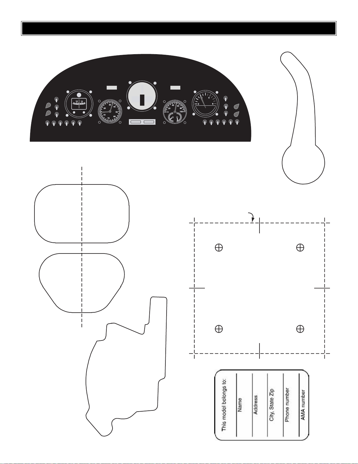
31
C
A
R
B
U
R
ETO
R
C
U
TO
U
T
FO
R
FU
JI BT-32
TEMPLATES
Instrument Panel
SPARK PLUG CUT OUT
FOR FUJI BT-32
AIR COOLING
INLET TEMPLA TE
CUT OUT ON
DOTTED LINE
DRILL 13/64" [5.2 mm]
(OR 3/16" [4.8 mm] HOLES)
1.2-1.8 GLOW ENGINE
MOUNTING TEMPLA TE
Page 32

 Loading...