

Great Planes GPMA1042 User Manual

WARRANTY
Great Planes®Model Manufacturing Co. guarantees this kit to be free from defects in both material and workmanship at the date of
purchase.This warranty does not cover any component parts damaged by use or modification. In no case shall Great Planes’liability
exceed the original cost of the purchased kit. Further, Great Planes reserves the right to change or modify this warranty without notice.
In that Great Planes has no control over the final assembly or material used for final assembly, no liability shall be assumed nor accepted
for any damage resulting from the use by the user of the final user-assembled product. By the act of using the user-assembled product,
the user accepts all resulting liability.
If the buyer is not prepared to accept the liability associated with the use of this product, the buyer is advised to return this kit
immediately in new and unused condition to the place of purchase.
READ THR OUGH THIS MANUAL BEFORE STARTING
CONSTRUCTION. IT CONTAINS IMPORTANT
INSTRUCTIONS AND WARNINGS CONCERNING
THE ASSEMBLY AND USE OF THIS MODEL.
GPMZ0255 for GPMA1042 V1.0 Entire Contents © Copyright 2001
1610 Interstate Drive Champaign, IL 61822
(217) 398-8970, Ext. 2
airsupport@greatplanes.com
INSTRUCTION MANUAL
Wingspan: 55.5 in [1410mm]
Wing area: 555 sq in [35.8 dm
2
]
Weight: 4.75 – 5.0 lbs [2.2 – 2.3 kg]
Wing loading: 19.7 – 20.8 oz/sq ft [59.7 – 62.9 g/dm
2
]
Length: 46 in [1170mm]
Radio: 4-channel with four servos
Engine: .40 - .46 cu in [6.5 - 7.5cc] two-stroke, .52 cu in
[8.5cc] four-stroke

INTRODUCTION................................................................2
SAFETY PRECAUTIONS..................................................2
ENGINE RECOMMENDATIONS ......................................3
ADDITIONAL ITEMS REQUIRED ....................................3
Hardware & Accessories................................................3
Adhesives & Building Supplies ......................................3
Optional Supplies & Tools ..............................................4
IMPORTANT BUILDING NOTES ......................................4
ORDERING REPLACEMENT PARTS ..............................5
METRIC CONVERSIONS..................................................5
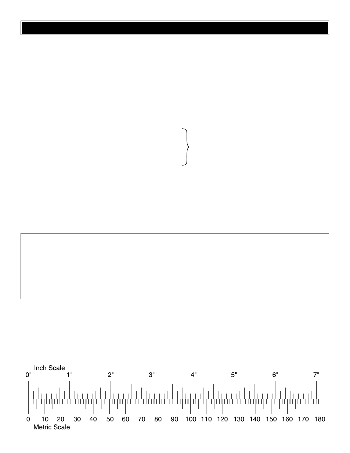
METRIC/INCH RULER ......................................................5
KIT CONTENTS ................................................................6
PREPARATIONS................................................................7
BUILD THE WING..............................................................7
Join the Wing......................................................................7
Assemble the Landing Gear ..............................................8
Hook Up the Ailerons ........................................................9
BUILD THE FUSELAGE..................................................11
Mount the Stab & Fin ......................................................11
Join the Elevators & Rudder............................................13
Mount the Engine ............................................................14
Install the Fuel Tank ........................................................15
FINAL ASSEMBLY ..........................................................15
Hookup the Controls ........................................................15
Finish the Cockpit ............................................................17
Fuelproof the Model ........................................................18
Apply the Decals..............................................................18
GET THE MODEL READY TO FLY..................................18
Balance the Model (C.G.) ................................................18
Balance the Model Laterally ............................................19
Check the Control Directions ..........................................19
Set the Control Throws ....................................................20
PREFLIGHT ....................................................................20
Identify Your Model ..........................................................20
Charge the Batteries........................................................20
Balance the Propellers ....................................................20
Ground Check..................................................................20
Range Check....................................................................21
ENGINE SAFETY PRECAUTIONS ................................21
AMA SAFETY CODE (excerpt)......................................21
CHECK LIST ....................................................................22
FLYING ............................................................................22
Takeoff..............................................................................22
Flight ................................................................................23
Landing ............................................................................23
Congratulations and thank you for purchasing the Great
Planes Super Sportster™40 MK II ARF. If you’re relatively
new to R/C airplanes, you may not have heard, but the
Super Sportster design has been around for several years.
It has been so successful, in fact, that it has made its own
place in model airplane history.No matter what your primary
interest or flight skills, because of its versatility, every
modeler who has mastered the basics of R/C flight should
own a Super Sportster.It can be flown fast like a pylon racer ,
relatively slow like a trainer, and of course, the Super
Sportster 40 MK II ARF can perform just about all the
aerobatics you can throw at it – it’s the perfect model!
If you’ve already mastered a high-wing trainer but haven’t
yet flown a low-wing sport model, we suggest a couple of
“check-flights” with an experienced modeler standing by to
assist. There’s nothing tricky about flying the Super
Sportster, and you’ll catch on quickly, but it doesn’t have the
self-righting characteristics of a basic high-wing trainer.
For the latest technical updates or manual corrections for
this model, visit the web site listed below and select the
Great Planes Super Sportster 40 MK II ARF. If there is new
technical information or changes to this ARF, a “tech notice”
box will appear in the upper left corner of the page.
http://www.greatplanes.com/airplanes/index.html
1.Your Great Planes Super Sportster 40 MK II ARF should
not be considered a toy, but rather a sophisticated, working
model that functions very much like a full-size airplane.
Because of its performance capabilities, the Super
Sportster, if not assembled and operated correctly, could
possibly cause injury to yourself or spectators and damage
to property.
2. You must assemble the model according to the
instructions. Do not alter or modify the model, as doing so
may result in an unsafe or unflyable model. In a few cases
the instructions may differ slightly from the photos.In those
instances the written instructions should be considered as
correct.
3.You must take time to build straight, true and strong.
4. You must use an R/C radio system that is in first-class
condition, and a correctly sized engine and components
(fuel tank, wheels, etc.) throughout the building process.
5. You must correctly install all R/C and other components
so that the model operates correctly on the ground and in
the air.
6.You must check the operation of the model before every
flight to insure that all equipment is operating and that the
model has remained structurally sound. Be sure to check
clevises or other connectors often and replace them if they
show any signs of wear or fatigue.
PRO TECT Y OUR MODEL,YOURSELF
& OTHERS...FOLLOW THESE
IMPORTANT SAFETY PRECAUTIONS
INTRODUCTION
TABLE OF CONTENTS
2
7. If you are not already an experienced R/C pilot, you
should fly the model only with the help of a competent,
experienced R/C pilot.
8.While this kit has been flight tested to exceed normal use,
if the plane will be used for extremely high stress flying,
such as actual racing, or if the model is to be flown with an
engine larger than the recommended range, the modeler is
responsible for taking steps to reinforce the high stress
points.
Remember:Take your time and follow the instructions
to
end up with a well-built model that is straight and true.
If you have not flown a low-wing model with ailerons before,
we recommend that you get the assistance of an
experienced pilot in your R/C club for your first flights. If
you’re not a member of a club, your local hobby shop has
information about clubs in your area whose membership
includes experienced pilots.
In addition to joining an R/C club, we strongly recommend
you join the AMA (Academy of Model Aeronautics). AMA
membership is required to fly at AMA sanctioned clubs.
There are over 2,500 AMA chartered clubs across the
country. Among other benefits, the AMA provides insurance
to its members who fly at sanctioned sites and events.
Additionally, training programs and instructors are available
at AMA club sites to help you get started the right way.
Contact the AMA at the address or toll-free telephone
number below:
Academy of Model Aeronautics
5151 East Memorial Drive
Muncie, IN 47302-9252
Tele. (800) 435-9262
Fax (765) 741-0057
Or via the Internet at: http://www.modelaircraft.org
The recommended engine size range for the Great Planes
Super Sportster 40 MK II ARF is .40 – .46 cu in [6.5 - 7.5cc]
two-stroke or .52 cu in [8.5cc] four-stroke. The prototype
was first tested with an O.S.®MAX .46 FX. If you like to fly
fast, this is the ideal engine.With a hot .46, at 4.75 lbs the
Super Sportster 40 MK II ARF was fast, yet remained solid,
stable and predictable. Later, the Sportster was test-flown
with an O.S. .52 four-stroke. If you prefer four-strokes, rest
assured, the .52 provides just as much fun.In fact, with a 12
x 6 prop, the vertical performance with the .52 was slightly
better than the .46. We did consider doing some flight
testing with a .70 four-stroke, and although the Super
Sportster 40 kit can be flown with a .70, this ARF version
has a lighter airframe, so a .70 would really be just too much
(not to mention the additional tail weight that would be
required to balance the model!).
Note: If using a “short” engine such as an O.S.MAX LA .40
– .46, you will have to make an engine mount spacer from
1/4" plywood (not supplied) as shown on page 23 in the
manual.
This is the list of hardware and accessories required to
finish the Great Planes Super Sportster 40 MK II ARF. Order
numbers are provided in parentheses.
❏ Engine and suitable propellers
❏ 2 oz. Pro
™
CA (Thin, GPMR6003)
❏ 4-channel radio with 4 standard servos
❏ 6" [150mm] Ser vo extension (to connect aileron servo
to receiver, HCAM2701 for Futaba®)
❏ 3' Medium fuel tubing (GPMQ4131)
❏ R/C foam rubber (1/4" [6mm] - HCAQ1000, or 1/2"
[13mm] - HCAQ1050)
❏ 2" [50mm] (1/6 scale) Pilot figure such as a William’s
Brother’s #180 racing pilot (WBRQ2480) or a #184
Sportsman pilot (WBRQ2484)
❏ Black paint for cockpit
❏ 1/4" [6mm] White Kwik Stripe striping tape (for canopy
trim, GPMQ1610)
In addition to common household tools and hobby tools, this
is a “short list” of the most important items required to build
this model.
Great Planes Pro CA and Epoxy glue is
recommended.
❏ 1/2 oz. Thin Pro CA (GPMR6001)
❏ 1/2 oz. Medium Pro CA (GPMR6007)
❏ 30-Minute Epoxy (GPMR6047)
❏ English drill bit sizes: 1/16", 3/32", 1/8", 5/32", 3/16"
-or-
❏ Metric drill bit sizes: 1.6mm, 2.4mm, 3.2mm, 4mm,
4.8mm
❏ Hobbico
®
Servo Horn drill (or #48 or 5/64") [2mm]
(HCAR0698)
Adhesives & Building Supplies
Hardware & Accessories
ADDITIONAL ITEMS REQUIRED
ENGINE RECOMMENDATIONS
We, as the kit manuf acturer, provide you with a top quality
kit and instructions, but ultimately the quality and flyability
of your finished model depends on how you build it;
therefore, we cannot in any way guarantee the
performance of your completed model, and no
representations are expressed or implied as to the
performance or safety of your completed model.
3
❏ 4-40 tap and #43 (or 3/32") [2.4mm] drill
-or-
❏ Great Planes 4-40 tap and drill set (GPMR8101)
❏ White or clear RTV (room temperature vulcanizing)
silicone sealer
❏ Masking tape
Here is a list of additional optional items we used to
assemble this model.
❏ CA activator (GPMR6034)
❏ Great Planes 3/32" and 7/64" long-handle hex
wrenches (GPMR8002, GPMR8003) Switch and
charge jack mounting set (GPMM1000)
❏ 21st Century
®
sealing iron (COVR2700)
❏ 21st Century iron cover (COVR2702)
❏ Top Flite
®
Trim Seal Tool™(TOPR2200)
❏ Microballoons (TOPR1090)
❏ Builders Triangle Set (HCAR0480)
❏ Dead Center
™
engine mount hole locator (GPMR8130)
❏ Great Planes Threadlocker
™
thread locking compound
(GPMR6060)
❏ K & S #801 Kevlar thread (for stab alignment
K+SR4575)
❏ Denatured Alcohol (for epoxy clean up)
❏ Curved Tip Canopy Scissors for trimming plastic
(HCAR0667)
❏ R/C-56 Canopy Glue (JOZR5007)
❏ Great Planes CG Machine
™
(GPMR2400)
❏ Great Planes AccuThrow
™
Deflection Gauge (for
measuring control throws, GPMR2405)
❏ Top Flite Precision Magnetic Prop Balancer
™
(TOPQ5700)
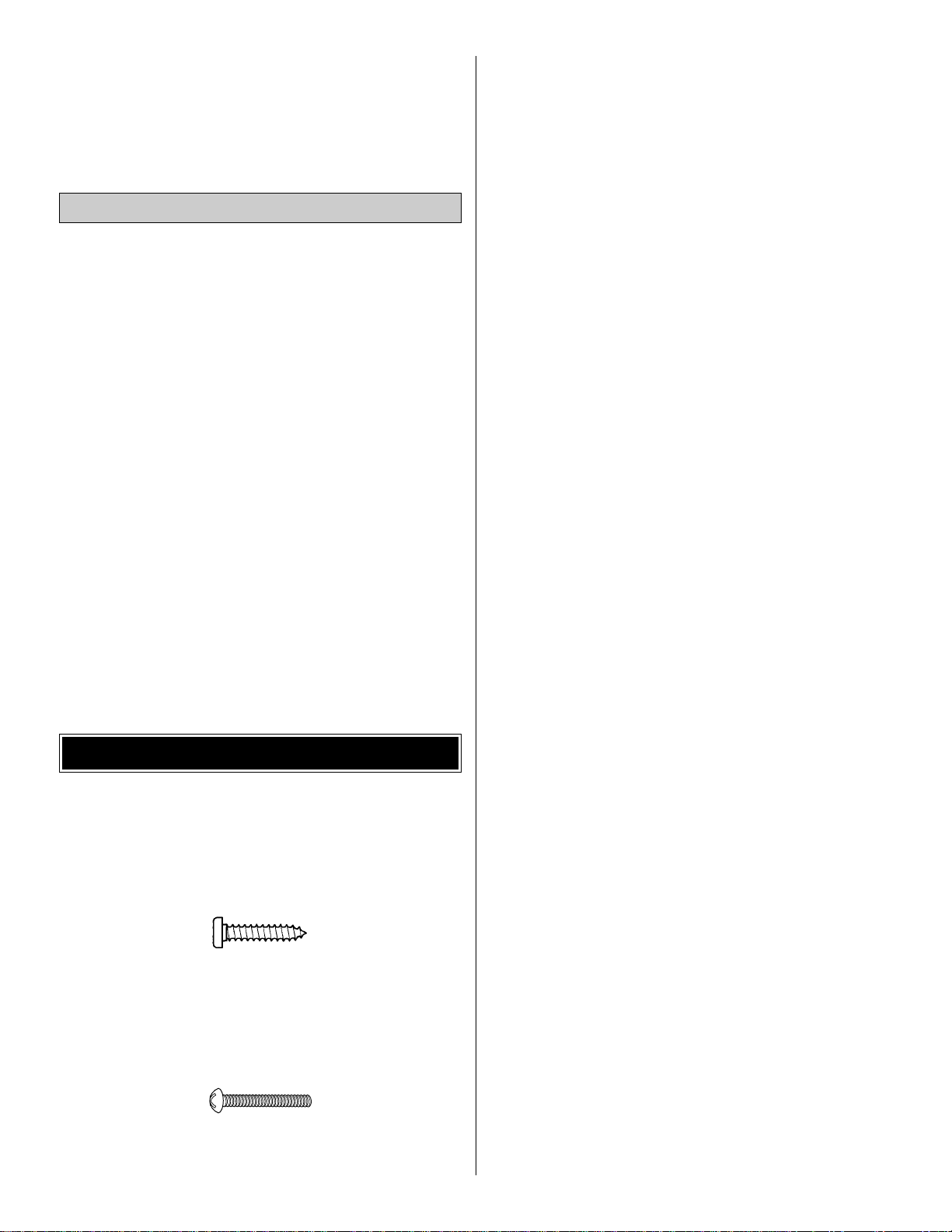
• There are two types of screws used in this kit:
Sheet metal screws are designated by a number and a
length. For example #6 x 3/4" [19mm].
This is a number six screw that is 3/4" [19mm] long.
Machine screws are designated by a number, threads per
inch, and a length. For example 4-40 x 3/4" [19mm].
This is a number four screw that is 3/4" [19mm] long with
forty threads per inch.
• When you see the term
test fit
in the instructions, it means
that you should first position the part on the assembly
without using any glue, then slightly modify or custom fit the
part as necessar y for the best fit.
• Whenever the term
glue
is written you should rely upon
your experience to decide what type of glue to use.When a
specific type of adhesive works best for that step, the
instructions will make a recommendation.
• Whenever just
epoxy
is specified you may use
either
30minute (or45-minute) epoxy or6-minute epoxy. When 30minute epoxy is specified it is highlyrecommended that you
use only 30-minute (or 45-minute) epoxy, because you will
need the working time and/or the additional strength.
• Photos and sketches are placed before the step they
refer to. Frequently you can study photos in following steps
to get another view of the same parts.
• The Great Planes Super Sportster 40 MK II ARF is factorycovered with Top Flite MonoKote®film. Should repairs ever
be required, MonoKote can be patched with additional
MonoKote purchased separately. MonoKote is packaged in
six-foot rolls, but some hobby shops also sell it by the foot.
If only a small piece of MonoKote is needed for a minor
patch, perhaps a fellow modeler would give you some.
MonoKote is applied with a model airplane covering iron, but
in an emergency a regular iron could be used. A roll of
MonoKote includes full instructions for application.Following
are the colors used on this model and order numbers for six
foot rolls.
Jet White TOPQ0204
Orange TOPQ0202
Red TOPQ0201
Sapphire Blue TOPQ0226
IMPORTANT BUILDING NOTES
Optional Supplies & Tools
4
5
ORDERING REPLACEMENT PARTS
To order replacement parts for the Great Planes Super Sportster 40 MK II ARF, use the order numbers in the Replacement
Parts List that follows. Replacement parts are available only as listed. Not all parts are available separately (an aileron
cannot be purchased separately, but is only available with the wing kit). Replacement par ts are not available from Product
Support, but can be purchased from hobby shops or mail order/Internet order firms. Hardware items (screws, nuts, bolts)
are also available from these outlets.If you need assistance locating a dealer to purchase parts, visit
www.greatplanes.com
and click on “Where to Buy.” If this kit is missing parts, contact Great Planes Product Support.
Replacement Parts List
Order Number Description Ho
w to Purchase
Missing pieces............................Contact Product Suppor t
Instruction manual......................Contact Product Support
Full-size plans............................Not available
GPMA2134......………........Wing Set
GPMA2135............………..Fuse Set
GPMA2136.........………….Tail Set Contact Your Hobby
GPMA2139.............……….Wheel Pants ........Supplier to Purchase
GPMA2137.....………....….Canopy These Items
GPMA2138.....………....….Landing Gear (L&R)
1/64" = .4 mm
1/32" = .8 mm
1/16" = 1.6 mm
3/32" = 2.4 mm
1/8" = 3.2 mm
5/32" = 4.0 mm
3/16" = 4.8 mm
1/4" = 6.4 mm
3/8" = 9.5 mm
1/2" = 12.7 mm
5/8" = 15.9 mm
3/4" = 19.0 mm
1" = 25.4 mm
2" = 50.8 mm
3" = 76.2 mm
6" = 152.4 mm
12" = 304.8 mm
18" = 457.2 mm
21" = 533.4 mm
24" = 609.6 mm
30" = 762.0 mm
36" = 914.4 mm
Metric Conversions
6
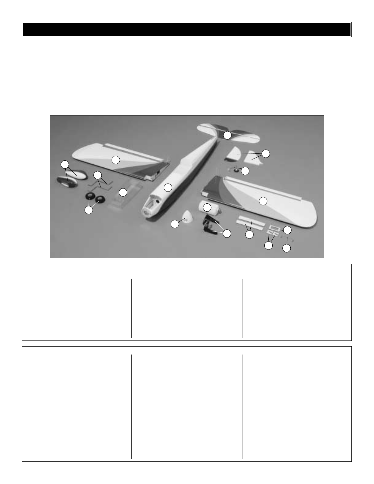
KIT CONTENTS
Before starting to build, use the Kit Contents list to take an inventory of this kit to make sure it is complete, and inspect
the parts to make sure they are of acceptable quality. If any parts are missing or are not of acceptable quality, or if you need
assistance with assembly, contact Great Planes Product Support. When reporting defective or missing parts, use the part
names exactly as they are written in the Kit Contents list on this page
Great Planes Product Support:
Phone: (217) 398-8970
Fax: (217) 398-7721
E-mail: airsupport@greatplanes.com
1. R & L Wing panels w/ailerons
2. Fuselage
3. Stab w/elevators
4. Fin w/rudder
5. Canopy
6. (2) Painted wheel pants
7. (2) Main landing gear wires
Kit Contents (Photographed)
8.
(2) 1/8" [3.2mm] Plywood wing joiners
9. Aileron servo mount
10. Elevator joiner wire
11. (2) 1/8" [3.2mm] Plywood inner
wheel pant mounts
12. Fuel tank w/hardware
13. Tail gear w/tail wheel
14. Great Planes .40 – .70 adjustable
engine mount
15. (2) 2-3/4" [70mm] Wheels
16. Spinner
(4) 6-32 x 3/4" [19mm] SHCS (socket-head cap
screws, engine mount to firewall)
(4) #6 Lock washers (engine mount to firewall)
(4) #6 Flat washers (engine mount to firewall)
(4) 4-40 x 3/4" [19mm] SHCS (engine to mount)
(4) #4 Lock washers (engine to mount)
(4) #4 Flat washers (engine mount)
(2) Tree of 4 nylon straps (wheel pants-2,
landing gear-4)
(8) #2 x 1/2" [13mm] Screws (landing gear straps)
(4) #2 x 3/8" [9.5mm] Screws (wheel pant straps)
(4) 5/32" [4mm] Wheel collars (main wheels)
(4) 6-32 Set screws (for wheel collars)
(1) Prebent tail gear wire w/nylon bearing
mount
(1) 1" [25mm] Tail wheel
(1) 3/32" [2.4mm] Wheel collar (tail wheel)
(1) 4-40 Set screw (tail wheel)
Kit Contents (Not Photographed)
(4) Faslinks (ailerons-2, elevator, rudder)
(5) Nylon clevis (ail.-2, throt, rudd, elev)
(5) Silicone retainers (clevises)
(2) 4-40 Nylon torque rod horn (ailerons)
(2) Large control horns (elev., rudd.)
(4) 2-56 x 1/2" [13mm] Phillips screws (control horns)
(1) Brass body screw-lock connector (throttle servo)
(1) 4-40 x 1/4" [6mm] SHCS (screw-lock connector)
(1) Nylon retainer (screw-lock connector)
(2) .074" x 36" [2 x 910mm] Threaded one-end
pushrod wire (elevator, rudder)
(2) .074" x 6" [2 x 150mm] Threaded one-end
pushrod wire (ailerons)
(1) .074" x 17-1/2" [2 x 445mm] Threaded one-
end pushrod wire (throttle)
(1) 3/16" x 12" [4.8 x 300mm] Guide tube
(throttle)
(1) 2" x 9" [50 x 230mm] CA hinge strip
(2) 1/4-20 x 2" [50mm] Nylon wing mounting
bolts
(2) 3/16" X 36" [ 4.8 x 910mm] Pushrod guide
tubes (preinstalled, elevator/rudder)
(2) 1/4-20 Blind nuts (preinstalled, wing mount)
(1) Decal sheet
1
1
2
3
5
12
6
7
15
16
14
8
11
10
9
4
13
❏ 1. If you have not yet done so already, remove the major
parts of the kit from the box (wings, fuse, wheel pants, cowl,
tail parts, etc.) and inspect them for damage.If any parts are
damaged or missing, contact Product Support at the
address or telephone number on page 6.
❏ 2. Remove the masking tape and separate the ailerons
from the wing, the rudder from the fin and the elevators from
the stab. Where necessary, use a covering iron with a
covering sock to tighten the covering that may have
loosened during storage or from removing the masking
tape. Apply pressure over sheeted areas to thoroughly
bond the covering to the wood.
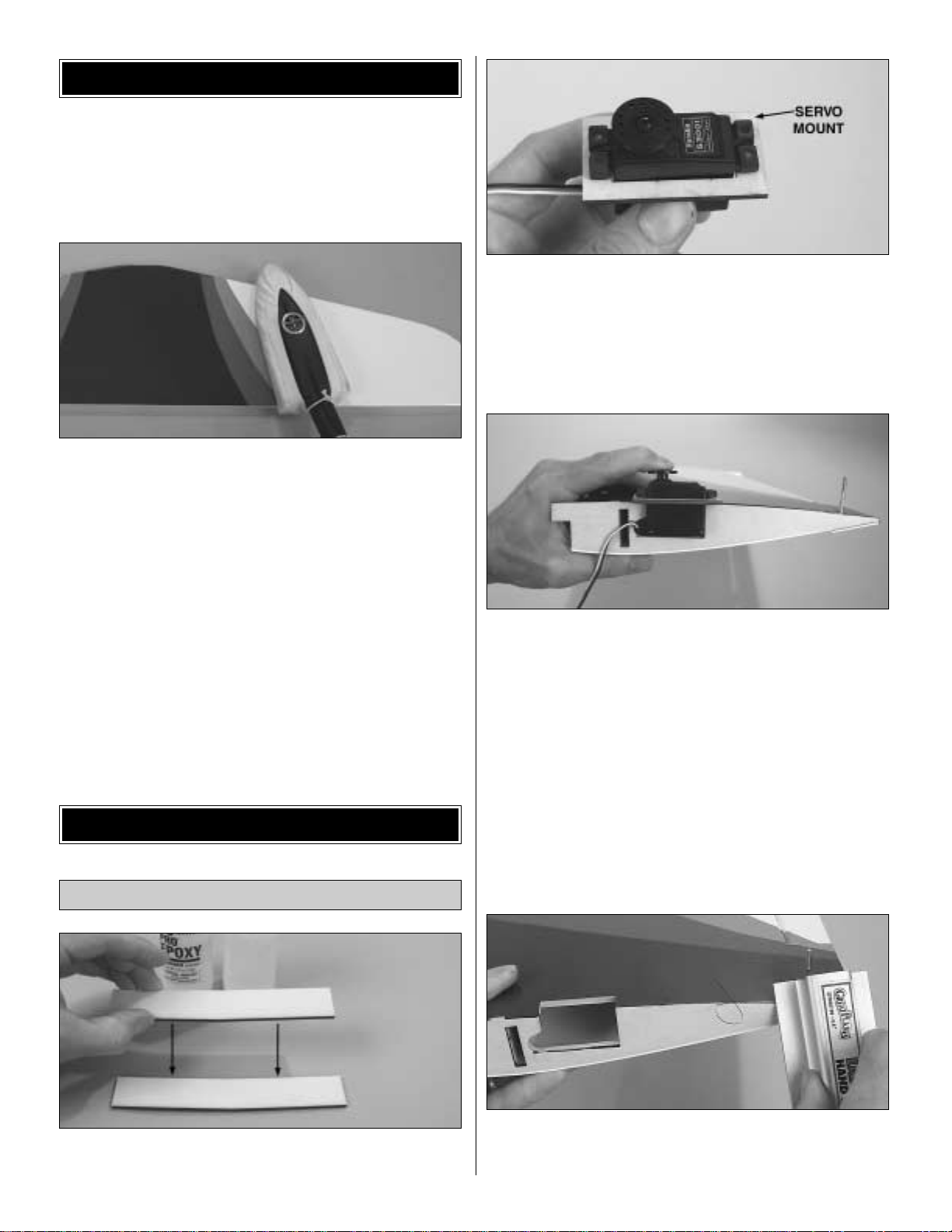
❏ 1. Use epoxy to glue both 1/8" [3.2mm] plywood wing
joiners together.
❏ 2. Test fit the aileron servo in the 1/8" [3.2mm] plywood
aileron servo mount. If necessary, trim the opening in the
mount to accommodate the servo.
❏ ❏ 3.Cut the sheeting over the aileron servo mounting
area
in the right wing panel to accommodate the servo. As you
can see in following photos, the servo will be centered in the
wing after the two panels are joined. Test fit the servo
and
the ply servo mount to the wing panel.Trim the center
rib
as
necessary to accommodate the servo and the servo
wire.
❏ 4. Prepare the other wing panel the same way.
❏ 5.T rim the covering from the ribs on the end of both wing
panels.This is easily done with a bar sander and
medium-grit
sandpaper as shown.
Join the Wing
BUILD THE WING
PREPARATIONS
7
❏ 6. Test fit the wing joiner in one wing panel, then the
other. Be cer tain the joiner is installed upright (the joiner is
angled upward for wing dihedral). Test fit the wing panels
together with the joiner. Make certain both panels fit well.
Make adjustments where required (it is possible that the
joiner may require slight sanding to remov e slivers or e xcess
epoxy that may interfere with the fit).
❏ 7. Once satisfied with the fit of the joiner and the wing,
thoroughly coat the inside of both wing panels where the
joiner fits and one half of the joiner with 30-minute epoxy.
Making certain the joiner is upright, inser t the coated end
into one of the wing panels. Coat the other end of the joiner
with the epoxy and join the other wing panel.
❏ 8.Wipe away epoxy that squeezes out from between the
wing halves.Use clamps and masking tape to hold the wing
together as shown. If you don’t have a clamp large enough
for the rear , use rubber bands instead.Be certain the joining
ribs on the ends of the wing panels accurately align. Again,
wipe away excess epoxy and do not disturb the wing until
the epoxy has fully hardened.
While the epoxy on the wing is hardening, go ahead and
work on the landing gear.
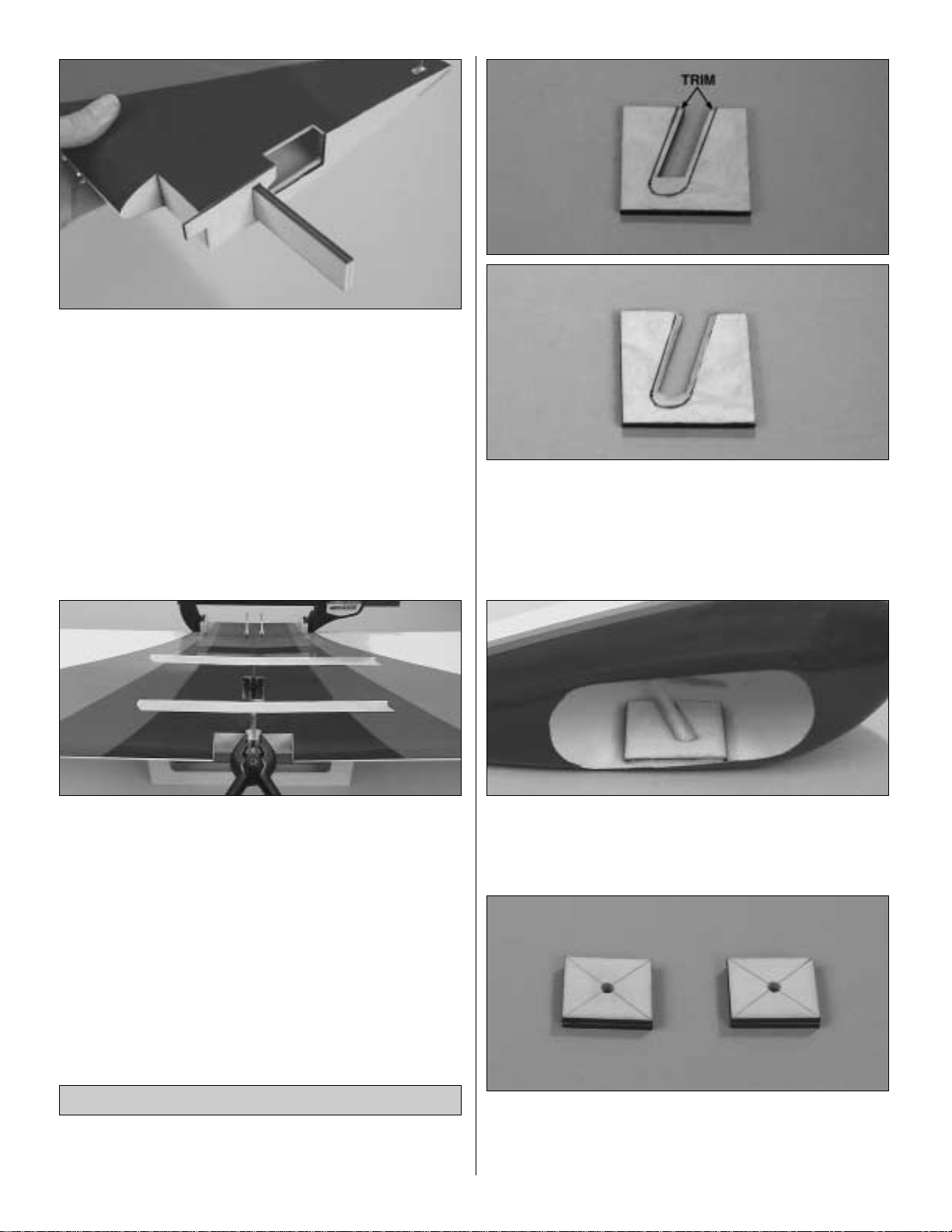
Although only the right wheel pant is shown in the photos,
both pants may be assembled at the same time.
❏ ❏ 1. Refer to the photo at step 2 to see how the 1/8"
[3.2mm] plywood inner wheel pant mount fits inside the
right wheel pant. Use a hobby knife to trim a bevel along the
inner edge of the cutout (indicated by the lines) so the
mount lays flat inside the pant.
❏ ❏ 2. Use epoxy mixed with microballoons or other
suitable
filler to securely glue the inner wheel pant mount to the
inside of the wheel pant.
Refer to this photo for the following two steps.
❏ ❏ 3.Glue together two 1/8" x 7/8" x 1" [3.2 x 22 x 25mm]
plywood outer wheel pant mounts. Glue together two
more mounts the same way. Use a straightedge to draw
lines on the mounts connecting the corners.
Assemble the Landing Gear
8
 Loading...