

Page 1
WARRANTY
Great Planes®Model Manufacturing Co. guarantees this kit to be free from defects in both material and workmanship at the date of
purchase. This warranty does not cover any component parts damaged by use or modification. In no case shall Great Planes’ liability
exceed the original cost of the purchased kit. Further, Great Planes reserves the right to change or modify this warranty without
notice.
In that Great Planes has no control over the final assembly or material used for final assembly, no liability shall be assumed nor
accepted for any damage resulting from the use by the user of the final user-assembled product. By the act of using the userassembled product, the user accepts all resulting liability.
If the buyer is not prepared to accept the liability associated with the use of this product, the buyer is advised to return this
kit immediately in new and unused condition to the place of purchase.
While this kit has been flight tested to exceed normal use, if the plane will be used for extremely high stress flying, the modeler is
responsible for taking steps to reinforce the high stress points.
READ THROUGH THIS MANUAL BEFORE
STARTING CONSTRUCTION. IT CONTAINS
IMPORTANT WARNINGS AND INSTRUCTIONS
CONCERNING THE ASSEMBLY AND USE OF
THIS MODEL.
GPMZ0218 for GPMA1040 V1.0© Copyright 2000
P.O. Box 788 Urbana, IL 61803 (217) 398-8970
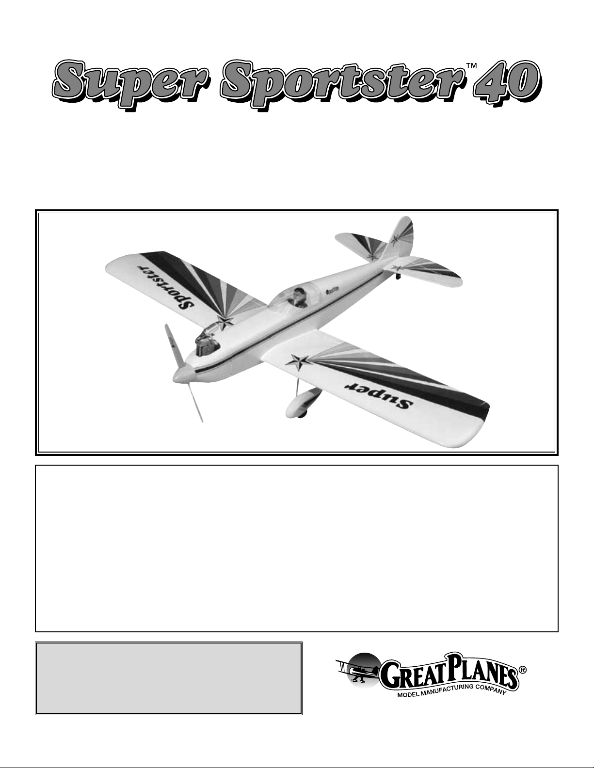
INSTRUCTION MANUAL
Wing Span - 55.5 in
Wing Area - 550 sq in
Weight - 5.5 lbs
Wing Loading - 23 oz/sq ft
Fuse Length - 46-3/4 in
A.R.F.
Almost Ready to Fly
Page 2
Important Safety Precautions .........................................2
Introduction ......................................................................2
Precautions.......................................................................2
Decisions You Must Make ...............................................3
Engine Selection..........................................................3
Preparations......................................................................3
Required Accessories ..................................................3
Building Supplies and Tools.........................................3
Optional Supplies and Tools ........................................3
General Inspection.......................................................4
Building Notes..............................................................4
Metric Conversions ......................................................4
Inch/Metric Ruler..........................................................4
Parts List......................................................................5
Begin Construction ..........................................................6
Wing Assembly ............................................................6
Wing Installation...........................................................8
Tail Installation .............................................................8
Fuel Tank Installation .................................................10
Engine Installation......................................................11
Landing Gear Installation...........................................12
Tail Gear Installation ..................................................13
Radio Installation .......................................................14
Battery & Receiver Installation ..................................16
Radio System Set-up.................................................16
Balance Your Model...................................................17
Balance Your Model Laterally ....................................17
Preparing To Fly Your Super Sportster ARF................18
Charge the Batteries..................................................18
Balance the Propeller ................................................18
Find a Safe Place to Fly ............................................18
Ground Check the Model...........................................18
Range Check Your Radio ..........................................18
Engine Safety Precautions ........................................18
AMA Safety Code (excerpt) ...........................................19
General ......................................................................19
Radio Control.............................................................19
Flying Your Super Sportster ARF .................................19
Takeoff .......................................................................19
Flying .........................................................................19
Landing ......................................................................19
Flight Log ..............................................Back Cover Page
Your Super Sportster ARF is not a toy, but rather a
sophisticated, working model that functions very much like a
full-size airplane. Because of its realistic performance, the
Super Sportster ARF, if not assembled and operated
correctly, could possibly cause injury to yourself or
spectators and damage property.
To make your R/C modeling experience totally enjoyable,
we recommend that you get experienced, knowledgeable
help from an instructor with assembly and during your first
flights. You’ll learn faster and avoid risking your model
before you’re truly ready to solo. Your local hobby shop has
information about flying clubs in your area whose
membership includes qualified instructors.
You can also contact the national Academy of Model
Aeronautics (AMA), which has more than 2,500 chartered
clubs across the country. Through any one of them,
instructor training programs and insured newcomer training
are available. Contact the AMA at the address or toll-free
phone number below:
Academy of Model Aeronautics
5151 East Memorial Drive
Muncie, IN 47302-9252
Tele. (800) 435-9262
Fax (765) 741-0057
Or via the Internet at:
http://www.modelaircraft.org
The Great Planes Super Sportster ARF is an easy to fly
sport scale airplane that closely resembles the full-size
Super Sportster both in appearance and performance. The
Super Sportster ARF is very stable and predictable, allowing
even novice skill level pilots to enjoy it.
Because of its docile flight characteristics, this airplane
could be used as a first airplane for learning to fly, but only
with the assistance and close supervision of a competent
instructor. This airplane lacks the self-recovery
characteristics of a true “basic trainer” such as the Great
Planes PT™series, which is the model of choice for learning
to fly.
1. You must assemble the model according to the
instructions. Do not alter or modify the model, as doing so
may result in an unsafe or unflyable model.
2. Take time to align the components straight, true and
strong.
3. Use an R/C radio system that is in first-class condition,
and a correctly sized engine and components (fuel tank,
wheels, etc.) throughout your assembly process.
4. You must properly install the R/C radio system and other
components so that the model operates properly on the
ground and in the air.
5. You must test the operation of the model before every
flight to insure that all equipment is operating and you must
make certain that the model has remained structurally
sound. Be sure to check clevises and other connectors often
and replace them if they show signs of wear or fatigue.
PRECAUTIONS
INTRODUCTION
PROTECT YOUR MODEL,YOURSELF
& OTHERS...FOLLOW THIS
IMPORTANT SAFETY PRECAUTION
TABLE OF CONTENTS
2
Page 3
Remember: Take your time and follow directions to end
up with a well-built model that is straight and true.
Please inspect all parts carefully before starting to
build! If any parts are missing, broken or defective, or if
you have any questions about assembling or flying this
airplane, please call us at (217) 398-8970. If you are
calling for replacement parts, please reference the part
names and numbers on page 5 and have them ready
when calling.
We can also be reached by e-mail at:
productsupport@greatplanes.com
Items in parentheses such as (GPMQ4243) are suggested
part numbers recognized by distributors and hobby shops
and are listed for your ordering convenience. GPM is the
Great Planes brand, TOP is the Top Flite®brand, and HCA
is the Hobbico®brand.
❏ Four-Channel Radio w/Four Servos
❏ One 6" Servo Extensions For Aileron Servos
❏ Engine – See Engine Selection
❏ Spare Glow Plugs (O.S. #8 For Most 2-Stroke
Engines–OSMG2691, or O.S. Type F for most
4-stroke engines–OSMG2692)
❏ Propeller (Top Flite Power Point
®
– Refer To Your
Engine’s Instructions For Proper Size)
❏ 3' Medium 3/32" Fuel Tubing (GPMQ4131)
❏ 1/4" Latex Foam Rubber Padding (HCAQ1000)
These are the building tools that are required. We
recommend Great Planes Pro™CA and Epoxy glue.
❏ 2 oz. Pro CA (Thin, GPMR6003)
❏ 2 oz. Pro CA+ (Medium, GPMR6009)
❏ CA Accelerator (GPMR6035)
❏ 6-Minute Pro Epoxy (GPMR6045)
❏ 30-Minute Pro Epoxy (GPMR6047)
❏ #1 Hobby Knife Handle (HCAR0105)
❏ #11 Blades (HCAR0311, 100 Qty)
❏ Builders Triangle Set (HCAR0480)
❏ Masking Tape (TOPR8018)
❏ Electric Power Drill
❏ Slip-Joint & Needle Nose Pliers
❏ Monofilament String For Stabilizer Alignment
❏ Screwdrivers (Flat Blade & Phillips)
❏ Pro Thread Locking Compound (GPMR6060)
❏ Isopropyl Alcohol (70%)
❏ Drill Bits: 1/16" [1.5mm], 5/64" [2mm], 3/32" [2.5mm],
3/16" [5mm], 7/32" [5.5mm], 1/4" [6mm], #29
❏ Top Flite Trim Seal Tool
™
(TOPR2200)
❏ Panel Line Pen (TOPQ2510)
❏ Sandpaper (80, 220 & 320-grit)
❏ Metal File
❏ Paper Towels
❏ T-Pins (HCAR5100)
❏ Razor Saw
❏ Petroleum Jelly
❏ CA Applicator Tips (HCAR3780)
❏ Epoxy Brushes (GPMR8060)
❏ Epoxy Mixing Sticks (GPMR8055, Qty. 50)
❏ CA Debonder (GPMR6039)
❏ Dremel
®
Moto-Tool™or Similar w/Cut-Off Wheel
❏ Hot Sock
™
(TOPR2175)
❏ Switch and Charge Jack (GPMM1000)
❏ Sealing Iron (TOPR2100)
❏ 6 oz. Segmented Lead Weight (GPMQ4485)
❏ C.G. Machine
™
(GPMR2400)
❏ Power Point
®
Balancer (TOPQ5700)
❏ Fingertip Prop Balancer (GPMQ5000)
❏ Accu-Throw
™
Deflection Gauge (GPMR2504)
Optional Supplies & Tools
Building Supplies & Tools
Required Accessories
PREPARATIONS
Engine Selection
There are several engines that will work well in your Super
Sportster ARF. We recommend a mild 2-stroke such as an
O.S.
®
.40FX or SuperTigre®G40. If you prefer a 4-stroke, an
O.S. FS-52 is an ideal choice. Your choice of 2-stroke or
4-stroke will determine the location of the throttle servo and
throttle pushrod exit on the firewall, so plan ahead.
DECISIONS YOU MUST MAKE
Note: We, as the manufacturer, provide you with a top
quality kit and great instructions, but ultimately the quality of
your finished model depends on how you assemble it;
therefore, we cannot in any way guarantee the performance
of your completed model, and no representations are
expressed or implied as to the performance or safety of your
completed model.
3
Page 4
Eliminate any wrinkles you find in the covering by shrinking
them away with a low temperature setting on a heat gun,
then apply pressure to the area with a covering iron and a
hot sock. This will securely bond the covering to the wood
so the wrinkles will be less likely to reappear in the future.
Several times during construction we refer to the “top” or
“bottom” of the model or a part of the model. It is understood
that the “top” or “bottom” of the model is as it would be when
the airplane is right side up and will be referred to as the
“top” even if the model is being worked on upside-down.
Building NotesGeneral Inspection
4
1/64" = .4mm
1/32" = .8mm
1/16" = 1.6mm
3/32" = 2.4mm
1/8" = 3.2mm
5/32" = 4mm
3/16" = 4.8mm
1/4" = 6.4mm
3/8" = 9.5mm
1/2" = 12.7mm
5/8" = 15.9mm
3/4" = 19mm
1" = 25.4mm
2" = 50.8mm
3" = 76.2mm
6" = 152.4mm
12" = 304.8mm
15" = 381mm
18" = 457.2mm
21" = 533.4mm
24" = 609.6mm
30" = 762mm
36" = 914.4mm
Metric Conversions
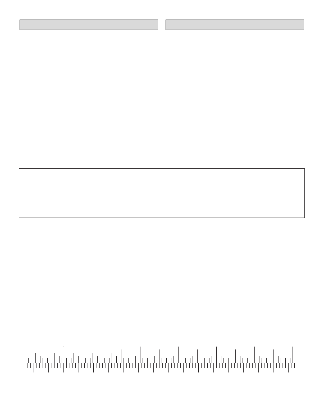
Inch Scale
0" 1" 2" 3" 4" 5" 6" 7"
0 10 20 30 40 50 60 70 80 90 100 110 120 130 140 150 160 170 180
Metric Scale
Page 5
5
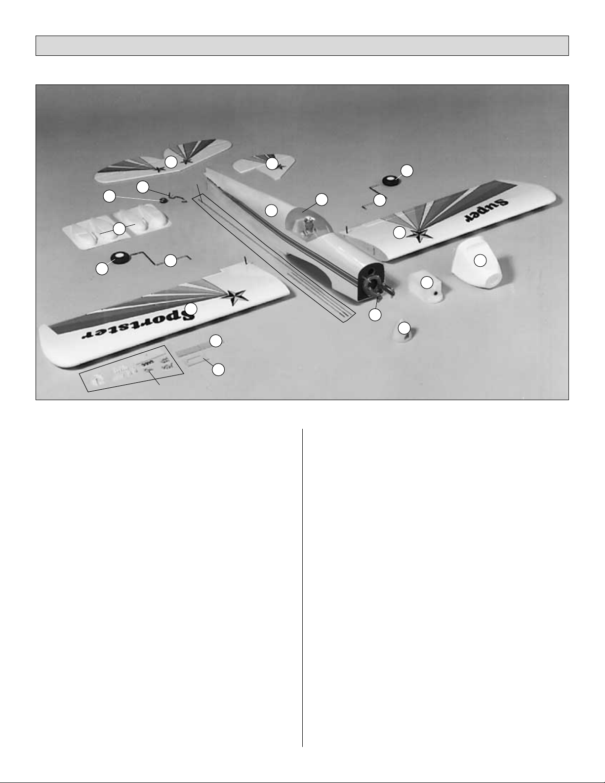
Key# Description Qty
1 Fuselage 1
2 Left Wing Panel w/Aileron 1
3 Right Wing Panel w/Aileron 1
4 Cowl 1
5 Adjustable Engine Mount 1
6 Fuel Tank 1
7 Canopy 1
8 Left & Right Wheel Pant Halves 1
9 Spinner 1
10 Landing Gear 2
11 Main Wheels 2
12 Stabilizer & Elevator Assembly 1
13 Tail Wheel 1
14 Rudder & Vertical Fin 1
15 Wing Joiner 1
16 Tail Wheel Wire 1
17 Aileron Servo Tray 1
* Pushrods 3
* Hardware Bag 1
* – Shown but not numbered
Replacement Parts
If needed, replacement parts for Super Sportster ARF are
available through your hobby supplier.
Wing Set .......................................................GPMA2125
Fuselage Kit..................................................GPMA2126
Tail Fin Set ....................................................GPMA2127
Canopy..........................................................GPMA2124
Cowl ..............................................................GPMA2129
Landing Gear Set..........................................GPMA2128
Wheel Pants..................................................GPMA2123
Parts List
2
3
1
4
10
10
14
12
15
8
6
9
13
16
11
11
Hardware
Pushrods
17
5
7
Page 6
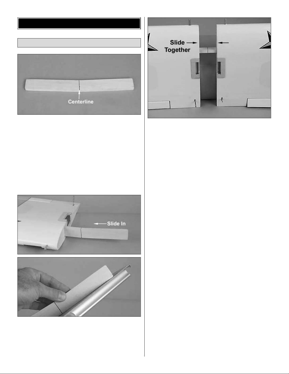
❏ 1. Draw a centerline on both sides of the wing joiner
as shown.
❏ ❏ 2. Test fit the wing joiner in both wing panels by
sliding
the joiner into the joiner cavity in the wing. The joiner must
slide in with little resistance up to the centerline drawn on
the joiner. Lightly sand the joiner edges, sides or ends if the
joiner will not fit in the cavity. Caution: A snug fit of the
joiner in the joiner cavity is desired. Do not sand the
joiner excessively.
❏ 3. Test fit the wing panels together with the joiner in
position. They must fit flush against each other without any
gaps. If the panels will not fit together tightly, lightly sand the
joiner edges, sides or ends. Caution: The wing panels
should fit together without any gaps.
Note: When performing the following steps, be sure to use
a sufficient amount of epoxy to form a complete and solid
bond between the wing joiner and the wing halves. This is
the most important glue joint in the entire airplane.
Please read the following three steps before mixing any
epoxy. You must complete these steps within 20
minutes from the time you mix the epoxy.
❏ 4. Mix 1/2 oz. [14ml] of 30-minute epoxy. Use a mixing
stick or epoxy brush to apply epoxy to all four sides of the
joiner cavity. Coat all surfaces of one half of the wing joiner
with 30-minute epoxy and place it in its corresponding joiner
cavity. Insert the joiner into the cavity up to the centerline
marked on the wing joiner. Be sure you are installing the
joiner to obtain the correct direction for the dihedral. Quickly
proceed to the next step.
❏ 5. Apply epoxy inside the joiner cavity of the remaining
wing panel. Next, coat the wing root ribs on both panels.
Coat the other half of the joiner with 30-minute epoxy and
join the other wing. Quickly proceed to the next step.
Wing Assembly
BEGIN CONSTRUCTION
6
Page 7

❏ 6. Assemble the two wing halves with the tightest seam
possible. No gaps should be showing between the two
halves. Use a paper towel dampened with alcohol to wipe
away any more epoxy that oozes out of the wing Use
several strips of masking tape on both sides of the wing to
hold them securely together. Let the epoxy fully cure before
continuing.
❏ Note: The exact dihedral angle (the angle at which the
wings are “bent up”) is not considered critical. This angle is
established by the angle of the root ribs and the dihedral
brace. As long as the wing halves fit together tightly, the
dihedral angle will be correct. If you wish to check the
dihedral angle,
place one wing panel flat on your work
surface. The
opposite wing panel should measure
approximately 1-7/8" [77mm] between the work surface and
the bottom of the wing.
❏ 7. Starting at the aft edge of the aileron servo tray, apply
the 1/2" [13mm] white wing center-section tape completely
around the wing over the joint. A small amount of pressure
should be applied to make a smooth seam.
❏ 8. Prepare the aileron servo with grommets and bushings
as shown in the sketch. Test fit the aileron servo into the
servo tray. Note that the notch in the tray corresponds to the
location of the servo lead wire. Enlarge the opening in the
servo tray, if needed, using a sharp hobby knife or fine
toothed file if needed. There should be a gap of about 1/64"
[.5mm] between the servo and the servo tray when installed
properly.
❏ 9. Drill 1/16" [1.5mm] pilot holes for the servo mounting
screws. Mount the servos with the screws provided with
your radio system. With the servo centered, trim and install
the servo horn as shown in the photo.
❏ 10. Thread the aileron control horns onto the torque rods
until they are positioned 1" [25mm] above the wing.
❏ 11. Locate two plastic clevises, two 6" [152mm] aileron
pushrods and clevis retainer. Thread the clevises 14-turns
onto the rods. Slide the clevis retainer down the rod and
partially over the clevis.
7
Page 8

❏ 12. Attach the clevises to the aileron control horns. Press
the forks of the clevises together until the pin snaps into the
opposite fork. Slide the clevis retainer into position over
the clevis forks.
❏ ❏ 13. Hold an aileron in its neutral position, and mark
the
pushrod wire where it crosses the outer hole on the servo
arm using a felt-tip pen.
❏ ❏ 14. Cut off the aileron pushrod approximately 3/8"
[10mm]
past the mark.
❏ ❏ 15. Make a 90º “L” bend at the mark that crosses the
servo arm.
❏ ❏ 16. Attach the rod to the servo arm. Use a plastic
FasLink
to secure the wire to the servo arm. You may need to
enlarge the holes in the servo arms slightly to allow the wire
to pass through the arm. (The Hobbico Quick Drill™set
HCAR0699 works well for this purpose.)
❏ 17. Repeat steps 13 to 16 for the opposite aileron.
❏ 1. Locate the holes for the wing bolts and remove the covering
from the top and bottom of the wing using a sharp hobby
knife.
❏ 2. Attach the wing to the fuselage using two 1/4-20 x 2"
nylon wing bolts.
❏ 1. Locate the slot for the horizontal stabilizer and vertical
fin
under the covering on the tail section of the fuselage by
gently pressing the covering with your finger. The elevator
slot is located on both sides of the fuselage. Using a sharp
hobby knife, carefully remove the covering, exposing the
slots. Note: Do not cut into the wood around the slot.
Tail Installation
Wing Installation
8
Page 9

❏ 2. Insert the stabilizer into the horizontal stabilizer slot so
it is centered in the fuselage (A). Place the wing onto the
fuselage and secure it with the 1/4-20 x 2" nylon bolts. View
the plane from behind at a distance of about 8 feet [2.4m] to
check the alignment of the stabilizer to the wing (B). If the
stabilizer is not parallel to the wing, remove the stabilizer
and sand the stabilizer base slightly on the high side.
Replace the stabilizer and check the alignment. Continue
this process until the wing and stabilizer are parallel.
❏ 3. Attach a piece of string with a T-pin to the center of the
fuselage as shown. Hold the string to one corner of the
horizontal stabilizer. Mark the position on the line, and then
swing the line over to the opposite tip on the stabilizer. If the
mark does not line up, adjust the positioning of the stabilizer
and repeat the “mark and swing” procedure until the
stabilizer is in proper alignment.
❏ 4. With the stabilizer properly aligned, use a felt-tip pen
to
trace around the tail of the airplane on the top and bottom of
the horizontal stabilizer.
❏ 5. Remove the stabilizer and draw two additional lines on
the top and two on the bottom, 1/16" [1.5mm] inside the
lines drawn in the previous step. Next, carefully cut through
the covering using a NEW #11 knife blade or soldering iron
at the inside lines and remove the covering from the center
on the top and bottom. If you are using a hobby knife, do
not cut the wood under the covering! This will seriously
weaken the stabilizer and could easily cause the
stabilizer to break in flight. If the stab breaks, the plane
has a very good chance of crashing. It is best to be very
careful when making this cut not to cut into the wood. The
covering must be removed from the center of the stab, or the
bond between the fuselage and stabilizer will be insufficient
and the stab may simply come off in flight.
❏ 6. Mix 1/4 oz. [7ml] of 30-minute epoxy. Using a mixing
stick,
apply a good layer of epoxy in the stabilizer opening in the
fuselage. Place a thin layer of epoxy on the stabilizer in the
area where the covering was removed. Insert the stabilizer
into the slot from the rear and check the alignment. Wipe off
any epoxy that squeezes out using a paper towel and
rubbing alcohol. Recheck the alignment several times while
the epoxy cures. Allow the epoxy to fully cure before
continuing to the next step.
❏ 7. Test fit the fin into the slot in the top of the fuselage.
Slide
the fin forward until the leading edge of the rudder is against
the fuselage. Align the hinge on the bottom of the rudder
with the slot in the aft edge of the fuselage. Check the
alignment of the fin with the centerline of the fuselage. A
straightedge against one side of the fin can be used to
check alignment. Make adjustments to the slot if necessary.
❏ 8. With the fin properly aligned, use a felt-tip pen to trace
a line along both sides of the bottom of the fin as was done
with the stabilizer. Remove the fin and draw an additional
line 1/16" [1.5mm] below the lines drawn in the previous
step. Next, carefully cut through the covering using a new
#11 knife blade or soldering iron at the inside lines and
remove the covering from the center on the top and bottom.
9
Page 10

If you are using a hobby knife, do not cut the wood
under the covering! This will seriously weaken the
stabilizer and could easily cause the stabilizer to break
in flight. If the fin breaks, the plane has a very good chance
of
crashing. It is best to be very careful when making this cut
not to cut into the wood. The covering must be removed
from
the bottom of the fin, or the bond between the fuselage and
fin will be insufficient and the fin may simply come off in
flight.
❏ 9. Remove the fin and mix up 1/4 oz. [7ml] of 30-minute
epoxy. Using a mixing stick, apply epoxy to the fuselage.
Apply epoxy to the bottom of the fin where the balsa wood
is exposed. Place the fin into the fuselage. Check to make
sure the fin is perpendicular to the stabilizer when viewed
from the rear of the airplane. (Use the sketch as a guide for
checking the alignment.) Check this alignment with the
fuselage (previous step) and stabilizer several times as the
epoxy cures. You may find it beneficial to hold the fin in
place
using masking tape and T-pins until the epoxy has cured.
❏ 1. Bend one of the tubes (referred to as the vent tube)
upwards
at a 45º angle. Heating the tube will make the bending
process much easier. Be very careful not to melt the tube
during the bending process. Note: When the stopper
assembly is installed into the fuel tank, the vent tube should
be 1/16" [1.5mm] from the top of the tank.
❏ 2. Locate the metal fuel pick-up weight (often referred to
as the “clunk”) and cut a 4" [102mm] piece of silicone fuel
tubing (not included). Install the clunk onto the tubing. Slide
the other end of the tubing onto the unbent tube. Measure
the distance from the end of the clunk to the back of the
stopper. Position the fuel tube so the distance measures
5" [127mm].
❏ 3. The stopper assembly can now be inserted into the
tank.
The vent tube should be adjusted so the vent tube is pointed
up towards the top of the tank. The rubber stopper must seat
against the lip of the tank. Make sure the tubes are
positioned side-to-side. Check to make sure the vent tube is
1/16" [1.5mm] from the top of the tank. Also, check to make
sure the clunk can move freely inside the tank, without
catching on the end of the tank. (It should clunk around in
the tank!) Once everything checks out, tighten the screw to
secure the stopper into the tank. Don’t overtighten the
screw
and strip out the rear compression disk! It would be a
good idea to mark which tube is the vent tube at this time.
❏ 4. Insert the fuel tank into the fuselage. The vent tube will
face towards the top of the fuselage.
❏ 5. Cut two pieces of fuel tubing (not included) 5" [127mm]
in length. Attach these to the tubes on the fuel tank. You may
need to hold the tank in position with one hand while
installing the tubes with the other.
Fuel Tank Installation
10
Page 11

❏ 1. Locate the 19-5/8" [498mm] throttle pushrod wire.
Attach
the “Z-bend” into the inside hole of the carburetor control
arm. Make sure the “Z-bend” does not interfere with any
parts of the engine.
The engine in your aircraft is mounted slightly different from
those in most R/C aircraft. This is done to allow the use of
many different types of engines. It also allows a “no-drill”
approach to ease the installation. Read through the
procedure and understand all the steps before actually
performing them.
❏ 2. The engine is “sandwiched” between the engine
mount
and the engine mount plates. Slide the throttle pushrod into
the pushrod housing and rest the engine on the mount. Slide
a #6 washer onto a 6-32 x 1" machine screw. Repeat this
process for all four screws and washers. Pass the screws
through the engine mount plates. The screws then go
through the mount, passing in front of and behind the engine
mounting flange. The plates will be resting on the top of the
engine’s mounting flanges. The 6-32 nuts are then placed
into the recesses on the bottom of the engine mount. Start
the screws, but do not tighten them at this time. We still
need to align the engine!
❏ 3. Install the spinner backplate, propeller, propeller
washer
and the propeller nut onto the engine. Turn the propeller
counterclockwise until it is against the smallest pins on the
backplate. Keep the propeller horizontal when the engine is
against its compression (the point at which you feel
resistance when you turn the crankshaft counterclockwise).
This is a good habit to get into when installing propellers
onto model airplanes. If the engine quits during flight, the
propeller will stop horizontally, therefore reducing the
chance of propeller breakage if you are forced to land on
rough terrain. Use an adjustable wrench (not a pliers) to
securely tighten the propeller nut.
❏ 4. Measure the distance from the back of the spinner
backplate
to the firewall. It should be 4-1/8" [105mm] on both sides.
Adjust the engine if needed and tighten the screws evenly to
secure the engine to the mount. Use thread-lock on the nuts
to prevent loosening.
❏ 5. Attach the fuel line (with the clunk) to the carburetor.
Engine Installation
11
Page 12

❏ 6. Remove the propeller, spinner backplate and muffler
from the engine. Slide the cowling into position. Temporarily
attach the propeller and spinner to the engine. Position the
cowling to have 1/8" [3mm] clearance between the back of
the spinner backplate and the front of the cowling. Drill 1/16"
[1.5mm] pilot holes for the cowl screws through the cowl and
into the fuselage at the marks on the cowl. Remove the
cowling, and drill the locations for the cowl mounting screws
into the cowl using a 1/8" [3mm] drill bit. Wick thin CA into
the 1/16" [1.5mm] holes on the fuselage to harden the wood,
which will prevent the screws from stripping out. Attach the
cowling to the fuselage using four #4 x 3/8" sheet metal
screws and four #4 washers.
❏ 7. Apply the decals onto the cowl as shown.
❏ 8. Attach the muffler to the engine. Carefully trim the
cowl,
removing small amounts of material as you progress to
allow for a 1/4" [6mm] clearance gap between the cowl and
the muffler. Attach the vent line to the muffler. Trim the cowl
so the vent line will not contact the cowl. If the vent line does
contact the cowl, it may break, which may cause the engine
to quit running during flight. Apply the supplied decals onto
the left and right sides of the cowl.
❏ 9. Install the spinner backplate, propeller, propeller
washer
and the propeller nut onto the engine. Trim the spinner cone
propeller slots if necessary so there is at least a 1/16"
[1.5mm] gap between the slots and the propeller. Once
satisfied with the fit, attach the cone with the screws
provided. Be careful not to overtighten these screws. They
are threaded into plastic, which can strip out easily if they
are overtightened.
❏ ❏ 1. On the bottom of the wing, there are two channels
for
the main landing gear. Locate these channels by running
your finger over the covering on the bottom of the wing. Use
a hobby knife to remove the covering from the channels.
❏ ❏ 2. Test fit the main landing gear wires into the holes.
If
they will not go in easily, drill out the two holes using a 5/32"
[4mm] drill bit. Next, use a drill bit or hobby knife to bevel the
inside corners of the holes so the bend in the wire will seat
fully into the holes and the wire will be flush with the bottom
of the wing.
❏ ❏ 3. Position the main landing gear in the hole inside
the
channel. Center the two nylon landing gear straps over the
struts so they are approximately 3/4" [19mm] from the ends
of the channel. Mark the holes using a felt-tip marker.
❏ ❏ 4. Drill eight holes for the landing gear straps using a
1/16" [1.5mm] drill bit.
❏ ❏ 5. Attach the nylon landing gear straps to the fuselage
using eight #2 x 1/2" sheet metal screws.
Landing Gear Installation
12
Page 13

❏ ❏ 6. Trim one matching set of wheel pant halves along
the molded in cut lines. Notice the inner and outer halves
interlock with each other. You can use a hobby knife to
carefully score along the cut lines and flex the plastic until
the excess breaks free, or use small scissors to cut along
the lines. Kyosho curved plastic cutting scissors
(KYOR1010) work extremely well for this and make the job
a cinch. For now, don’t worry about accurately cutting out
the opening in each wheel pant half – just cut an
approximate opening for the wheels.
❏ ❏ 7. Make two wheel pant mounts by cutting pieces of
scrap wood to a length of 1/2" [13mm]. Use medium CA to
glue two wheel pant mounts to the inside of each wheel pant
as shown.
❏ ❏ 8. Join two wheel pant halves and carefully spot glue
them together in just a few places with thin CA. Start by spot
gluing the top, then the front and rear where the two halves
just butt together. After the halves are joined, securely glue
them together along all the seams with medium CA. Note:
Do not use CA accelerator on the ABS plastic as it may
develop cracks and/or keep the paint from adhering.
❏ ❏ 9. Test fit the wheel pant halves and make
adjustments
where necessary for the best possible fit.
❏ ❏ 10. File a flat spot along the bottom of the axle. This
provides
a better area for the set screw to bite and helps keep the
wheel in place. Install the wheel pants by placing these
items onto the landing gear wire in this order: Wheel pant,
5/32" wheel collar, wheel, 5/32" wheel collar. Thread a 6-32
set screw into each of the wheel collars. Check to make sure
the wheels rotate without binding on the wheel pant. If not,
loosen the set screws on the wheel collars and adjust the
position of the wheel.
❏ 1. Locate the plywood tail gear plate. Position the plate
onto
the rear of the fuselage. Trace around the plate using a felt-
tip
marker. Remove the plate, and carefully remove the
covering from the fuselage in the position of the plate using
a hobby knife. Glue the plate onto the fuselage using
6-minute epoxy. Allow the epoxy to fully cure before
continuing to the next step.
❏ 2. Position the tail gear assembly onto the plywood plate
and mark the locations for the mounting screws. Use a 1/16"
[1.5mm] drill to drill the locations for the screws. Attach the
Tail Gear Installation
13
Page 14

tail gear assembly to the plate using two #2 x 1/2" sheet
metal screws.
❏ 3. Slide the tail gear actuator onto the tail gear wire. Mark
the location of the actuator on the rudder and remove the
covering inside those marks. Use 6-minute epoxy to attach
the actuator to the rudder.
❏ 1. Mount the rudder, elevator and throttle servos in the
fuselage.
Use the following sequence for mounting the servos into the
servo tray:
❏ A. Install rubber grommets and brass eyelets in the
servos
using the provided sketch.
❏ B. Test fit the servos in the tray. Enlarge the openings if
needed to create a 1/32" [.8mm] gap around the servo.
❏ C. Mark servo mounting hole locations on the tray, then
drill 1/16" [1.5mm] pilot holes through each mark.
❏ D. Mount the servos with the screws provided with your
radio system.
❏ 2. Install the rudder nylon control horn in line with the
pushrod
exit. Hold the horn in position and mark the location of the
mounting holes. Drill 3/32" [2.5mm] mounting holes through
the marks. Wick two to three drops of thin CA into the holes
to harden the underlying balsa, and then re-drill the holes.
Attach the horn using two 2-56 x 5/8" machine screws and
a nylon nut plate. Do not overtighten the screws,
crushing the underlying balsa.
❏ 3. Install the rudder pushrod. Place a clevis retainer onto
a
clevis. Thread the clevis 14-turns onto the pushrod. Attach
the clevis to the outside hole on the control horn. Slightly
bend the pushrod as necessary to allow free movement.
❏ 4. Center the rudder and rudder servo and mark the
pushrod
where it crosses the servo arm. Enlarge the servo horn hole
with a 5/64" [2mm] drill bit. (The Hobbico Quick Drill set
(HCAR0699) works well for this purpose.)
Radio Installation
14
Page 15

❏ 5. Make a 90º bend in the pushrod on your mark, then
insert it through the enlarged hole in the servo arm. Secure
the wire in place with a nylon FasLink. Trim the excess wire
1/16" [1.5mm] above the FasLink.
❏ 6. Install the elevator control horn by positioning the horn
as close to the inboard edge of the elevator as possible and
mark the location of the mounting hole. Drill 3/32" [2.5mm]
mounting holes through the marks. Wick two to three drops
of thin CA into the holes to harden the underlying balsa, then
re-drill the holes. Attach the horns using two 2-56 x 5/8"
machine screws and a nylon nut plate. Do not overtighten
the screws, crushing the underlying balsa.
❏ 7. Install the elevator pushrod. Place a clevis retainer
onto
the clevis. Thread the clevis 14-turns onto the pushrod.
Attach the clevis to the outer hole of the control horn.
Slightly bend the pushrod wire as necessary to allow for free
movement.
❏ 8. Center the elevator and elevator servo and mark the
pushrod where it crosses the servo arm. Enlarge the servo
horn hole with a 5/64" [2mm] drill bit.
❏ 9. Make a 90º bend in the pushrod on your mark, then
insert it through the enlarged hole in the servo arm. Secure
the wire in place with a nylon FasLink. Trim the excess wire
1/16" [1.6mm] above the FasLink.
❏ 10. Install a brass screw-lock pushrod connector with the
4-40 x 1/8" cap screw on the throttle servo horn. Snap the
nylon retainer onto the screw-lock pushrod connector post
beneath the servo horn.
RETAINER
15
Page 16

❏ 1. Wrap the receiver and battery as shown in the sketch.
❏ 2. Install the switch on the side of the fuselage opposite
the
muffler as shown. Use the switch plate as a template when
drilling and cutting the fuselage.
❏ 3. Hook up – following the manufacturer’s
recommendations
– the receiver, switch harness and battery as shown in the
photo. At this time, it is suggested to allow the receiver and
battery the option of being moved until after the aircraft has
been balanced. Once balanced, the receiver and battery
must be secured into the aircraft to prevent them from
moving during flight. Once your model has been balance,
secure the location of the receiver and battery using the
wood supplied in the kit.
❏ 4. Route the antenna to the tail of the model. You may
use your preferred method or the method we use in the
Great Planes model shop. Drill a 1/4" [6mm] hole through
the fuse side in the proximity of the receiver. Cut a 1/2"
[13mm] long piece of fuel tubing and install it in the hole.
Install a strain relief (as shown in the sketch), then route the
antenna through the fuel tubing to the bottom of the fuse at
the tail. Use a rubber band to attach the antenna to a T-pin
at the aft end of the fuselage. Do not cut or shorten the
antenna wire. Leave any excess to hang free.
❏ 1. Turn on the transmitter and then the receiver. Standing
behind the plane, make the following movements with the
transmitter and observe the control surfaces:
If any of the servo movements are wrong, reverse the servo
direction with the servo reversing switches on the
transmitter.
❏ 2. For added safety and convenience, the throttle
should
be set up so the engine can be stopped using the throttle
trim. To do this, loosen the screw on the pushrod connector,
move the throttle pushrod so the carburetor is completely
closed with the throttle stick, and trim lever on the
transmitter fully back. (Note: If the carburetor does not fully
close, adjust the idle stop screw on the carburetor until it
will.) Next, tighten the screw on the pushrod connector. Test
the trim lever by advancing it to full. This will be a fast idle
position with the carburetor barrel open slightly (about
1/32" or .8mm).
Now move the throttle stick forward to full. Make sure the
carburetor barrel opens all the way. (See sketch.) If it
doesn’t open far enough or opens too far (bending the rod)
move the pushrod connector in or out on the servo arm
and/or the carburetor arm to gain or reduce movement.
Apply a small amount of thin CA onto the threads of the
pushrod connector. The throw will be correct when the
carburetor barrel will stop fully open at the same time the
throttle stick reaches full. With the throttle set up properly,
you should be able to run the engine with the trim lever set
midway to the full position (adjusted for a smooth but slow
idle). Then when it is time to stop the engine, simply pull
back
the trim to close the carburetor and the engine will stop
running.
❏ 3. Check the movement of the control surfaces. Use a
ruler to match our measurements listed below. If your radio
features dual rates, set up both the high and low rates
following the radio system’s instructions. If your radio does
not have dual rates, set up the plane using low rates first
and increase the throws as you get familiar with the plane.
4-CHANNEL
TRANSMITTER
4-CHANNEL
TRANSMITTER
4-CHANNEL
TRANSMITTER
4-CHANNEL RADIO SET-UP
(STANDARD MODE 2)
TRANSMITTER
4-CHANNEL
ELEVATOR MOVES UP
RIGHT AILERON MOVES UP
LEFT AILERON MOVES DOWN
RUDDER MOVES RIGHT
CARBURETOR WIDE OPEN
Radio System Set-up
Battery & Receiver Installation
16
Page 17

Low Rate High Rate
Aileron 3/16" [5mm] up 3/8" [9.5mm] up
3/16" [5mm] down 3/8" [9.5mm] down
Elevator 7/16" [11mm] up 5/8" [16mm] up
7/16" [11mm] down 5/8" [16mm] down
Rudder 1" [25mm] left 1-3/16" [30mm] left
1" [25mm] right 1-3/16" [30mm] right
These are the suggested deflection from center of the
control surface.
If you need more control movement, you should move the
clevis to a hole closer to the control surface or you can move
the rod at the servo away from the center of the servo. If you
have too much movement, do the opposite. See the
following sketches:
Note: This section is VERY important and must NOT be
omitted! A model that is not properly balanced will be
unstable and possibly unflyable.
❏ 1. The balance point (C.G.) is located 3-5/16" [84mm]
back
from the leading edge of the wing against the fuselage.
Balance your Super Sportster using a Great Planes C.G.
Machine™Airplane Balancer (GPMR2400) for the most
accurate results. This is the balance point at which your
model should balance for your first flights. After initial trim
flights and when you become more acquainted with your
Super Sportster, you may wish to experiment by shifting the
balance up to 1/4" [6mm] forward or backward to change its
flying characteristics. Moving the balance forward may
improve the smoothness and stability, but the model may
then require more speed for takeoff and may become more
difficult to slow for landing. Moving the balance aft makes
the model more agile with a lighter, snappier “feel” and often
improves knife-edge capabilities. In any case, please start at
the location we recommend. Do not at any time balance
your model outside the recommended range.
❏ 2. With the wing attached to the fuselage, all parts of the
model installed (ready to fly), and an empty fuel tank, block
up the tail as necessary to level the stab. Lift the model at
the desired balance point, and observe the tail of the
aircraft. If the tail drops, the model is “tail heavy” and you
must add weight* to the nose to balance the model. If the
nose drops, it is “nose heavy” and you must add weight* to
the tail to balance the model.
Note: Nose weight may be easily installed by using a
“spinner weight.” Tail weight may be added by using Great
Planes (GPMQ4485) “stick-on” weights.
*If possible, first attempt to balance the model by changing
the position of the receiver battery. If you are unable to
obtain good balance by doing so, then it will be necessary to
add weight to the nose or tail to achieve the proper balance
point. Remember to secure the receiver and battery after
your model has been balanced.
IMPORTANT: Do not confuse this procedure with “checking
the C.G.” or “balancing the airplane fore and aft.”
Now that you have the basic airplane nearly completed, this
is a good time to balance the airplane laterally (side-to-side).
Here is how to do it:
❏ 1. Assemble the model in as in preparation for flight. (No
fuel is required for this procedure.)
❏ 2. With the wing level, lift the model by the engine
propeller
shaft and the fin post (this may require two people). Do this
several times.
❏ 3. If one wing always drops when you lift the model, it
means
that side is heavy. Balance the airplane by adding weight to
the opposite, lighter wing tip.
Note: An airplane that has been laterally balanced will track
better in loops and other maneuvers.
Balance Your Model Laterally
Balance Your Model
results in more throw.
Moving the clevis inward on the control horn
throw
More
throw
More
More
movement
results in more pushrod movement.
Moving the clevis outward on the servo arm
Less
movement
movement
More
17
Page 18

Follow the battery charging procedures in your radio
instruction manual. You should always charge your
transmitter and receiver batteries the night before you go
flying, and at other times as recommended by the radio
manufacturer.
Balance your propellers carefully before flying. An
unbalanced prop is the single most significant cause of
damaging vibration. Not only will engine mounting screws
and bolts vibrate out, possibly with disastrous effect, but
vibration will also damage your radio receiver and battery.
Vibration will cause your fuel to foam, which will, in turn,
cause your engine to run rough or quit.
We use a Top Flite Precision Magnetic Prop Balancer
™
(#TOPQ5700) in the workshop and keep a Great Planes
Fingertip Balancer™(#GPMQ5000) in our flight box.
The best place to fly your R/C model is an AMA (Academy
of Model Aeronautics) chartered club field. Ask your hobby
shop dealer if there is such a club in your area and join. Club
fields are set up for R/C flying and that makes your outing
safer and more enjoyable. The AMA also can tell you the
name of a club in your area. We recommend that you join
the AMA and a local club so you can have a safe place to fly
and have insurance to cover you in case of a flying accident.
(The AMA address and phone numbers are listed on page 2
of this instruction manual).
If a club and its flying site are not available, you need to find
a large, grassy area at least 6 miles away from any other
R/C radio operation like R/C boats and R/C cars and away
from houses, buildings and streets. A schoolyard may look
inviting but it is too close to people, power lines and possible
radio interference.
If you are not thoroughly familiar with the operation of R/C
models, ask an experienced modeler to check to see that
you have the radio installed correctly and that all the control
surfaces do what they are supposed to. The engine
operation also must be checked and the engine “broken-in”
on the ground by running the engine for at least two tanks of
fuel. Follow the engine manufacturer’s recommendations for
break-in. Check to make sure all screws remain tight, that
the hinges are secure and that the prop is on tight.
Wherever you do fly, you need to check the operation of the
radio before every time you fly. First, make sure no one else
is on your frequency (channel). With the transmitter antenna
collapsed and the receiver and transmitter on, you should
be able to walk at least 100 feet away from the model and
still have control. Have someone help you. Have them stand
by your model and, while you work the controls, tell you
what the various control surfaces are doing.
Repeat this test with the engine running at various speeds
with an assistant holding the model. If the control surfaces
are not always acting correctly, do not fly! Find and correct
the problem first.
Note: Failure to follow these safety precautions may result
in severe injury to yourself and others.
Keep all engine fuel in a safe place, away from high heat,
sparks or flames, as fuel is very flammable. Do not smoke
near the engine or fuel; and remember that the engine
exhaust gives off a great deal of deadly carbon monoxide.
Therefore do not run the engine in a closed room or garage.
Get help from an experienced pilot when learning to operate
engines.
Use safety glasses when starting or running engines.
Do not run the engine in an area of loose gravel or sand, as
the propeller may throw such material in your face or eyes.
Keep your face and body as well as all spectators away from
the plane of rotation of the propeller as you start and run
the engine.
Keep items such as these away from the prop: loose
clothing, shirt sleeves, ties, scarfs, long hair or loose objects
(pencils, screwdrivers) that may fall out of shirt or jacket
pockets into the prop.
Use a “chicken stick” device or electric starter; follow the
instructions supplied with the starter or stick. Make certain
the glow plug clip or connector is secure so that it will not
pop off or otherwise get into the running propeller.
Engine Safety Precautions
Range Check Your Radio
Ground Check the Model
Find a Safe Place to Fly
Balance the Propeller
Charge the Batteries
PREPARING TO FLY YOUR
SUPER SPORTSTER ARF
18
Page 19

Make all engine adjustments from behind the rotating
propeller.
The engine gets hot! Do not touch it during or after
operation. Make sure fuel lines are in good condition so fuel
will not leak onto a hot engine, causing a fire.
To stop the engine, cut off the fuel supply by closing off the
fuel line or follow the engine manufacturer’s
recommendations.
Do not use hands, fingers or any body part to try to stop the
engine. Do not throw anything into the prop of a running
engine.
Read and abide by the following Academy of Model
Aeronautics Official Safety Code excerpt:
General
1. I will not fly my model aircraft in sanctioned events, air
shows, or model flying demonstrations until it has been
proven to be airworthy by having been previously
successfully flight tested.
2. I will not fly my model aircraft higher than approximately
400 feet within 3 miles of an airport without notifying the
airport operator. I will give right of way to, and avoid flying in
the proximity of, full-scale aircraft. Where necessary an
observer shall be used to supervise flying to avoid having
models fly in the proximity of full-scale aircraft.
3. Where established, I will abide by the safety rules for the
flying site I use, and I will not willfully and deliberately fly my
models in a careless, reckless and/or dangerous manner.
7. I will not fly my model unless it is identified with my name
and address or AMA number, on or in the model.
9. I will not operate models with pyrotechnics (any device
that explodes, burns, or propels a projectile of any kind).
Radio Control
1. I will have completed a successful radio equipment
ground check before the first flight of a new or repaired
model.
2. I will not fly my model aircraft in the presence of
spectators until I become a qualified flier, unless assisted by
an experienced helper.
3. I will perform my initial turn after takeoff away from the pit
or spectator areas, and I will not thereafter fly over pit or
spectator areas, unless beyond my control.
4. I will operate my model using only radio control
frequencies
currently allowed by the Federal Communications
Commission.
The Super Sportster ARF is a great flying sport airplane that
flies smoothly and predictably, yet is highly maneuverable. It
does not have the self-recovery characteristics of a primary
trainer, therefore you must either have mastered the basics
of R/C flying or seek the assistance of a competent R/C pilot
to help you with your first flights.
If you have dual rates on your transmitter, set the switches
to “high rate” for takeoff, especially when taking off in a
crosswind. Although Super Sportster ARF has great low
speed characteristics, you should always build up as much
speed as your runway will permit before lifting off, as this will
give you a safety margin in case of a “flame-out.” When the
plane has sufficient flying speed, lift off by smoothly applying
a little up elevator (don’t “force” it off to a vertical climb!),
and climb out gradually.
We recommend that you take it easy with your Super
Sportster ARF for the first several flights and gradually “get
acquainted” with this fantastic ship. Add and practice one
maneuver at a time, learning how she behaves in each one.
We particularly enjoy the ease with which the Super
Sportster ARF flies inverted, with very little down elevator
required! Spins and inverted spins are also performed with
ease. Knife edge and point rolls are possible, but they
require some aileron and elevator correction.
When it’s time to land and you cut the throttle, you’ll notice
a very slight climbing tendency at first, which bleeds off
some speed; then it assumes the normal glide angle, slightly
nose down.
Have a ball! Always stay in control and fly in a safe manner.
GOOD LUCK AND GREAT FLYING!
Landing
Flying
Takeoff
FLYING YOUR SUPER
SPORTSTER ARF
AMA SAFETY CODE (excerpt)
19
Page 20

BUILDING NOTES
Kit Purchased Date: _______________________
Where Purchased:_________________________
Date Construction Started: __________________
Date Construction Finished: _________________
Finished Weight: __________________________
Date of First Flight: ________________________
FLIGHT LOG
 Loading...