

Page 1

READ THROUGH THIS MANUAL BEFORE
STARTING CONSTRUCTION. IT CONTAINS
IMPORTANT INSTRUCTIONS AND WARNINGS
CONCERNING THE ASSEMBLY AND USE OF
THIS MODEL.
GPMZ0221 for GPMA1038 V1.1© Copyright 2003
INSTRUCTION MANUAL
Printed in USA
Champaign, Illinois
(217) 398-8970, Ext 5
airsupport@greatplanes.com
Great Planes
®
Model Manufacturing Co. guarantees this kit to
be free from defects in both material and workmanship at the date
of purchase. This warranty does not cover any component parts
damaged by use or modification.In no case shall Great Planes’
liability exceed the original cost of the purchased kit. Further,
Great Planes reserves the right to change or modify this warranty
without notice.
In that Great Planes has no control over the final assembly or
material used for final assembly, no liability shall be assumed nor
accepted for any damage resulting from the use by the user of the
final user-assembled product. By the act of using the userassembled product, the user accepts all resulting liability.
If the buyer is not prepared to accept the liability associated
with the use of this product, the buyer is advised to return
this kit immediately in new and unused condition to the place
of purchase.
To make a warranty claim send the def ective part or item to Hobby
Services at the address below:
Hobby Services
3002 N. Apollo Dr. Suite 1
Champaign, IL 61822
USA
Include a letter stating your name, return shipping address, as
much contact information as possible (daytime telephone number,
fax number, e-mail address), a detailed description of the problem
and a photocopy of the purchase receipt. Upon receipt of the
package the problem will be evaluated as quickly as possible.
WARRANTY
Page 2

Introduction.......................................................................2
Important Safety Precautions .........................................2
Decisions You Must Make................................................3
Engine Selection..........................................................3
Radio Equipment.........................................................3
Additional Items Required...............................................3
Hardware and Accessories ..........................................3
Building Supplies and Tools.........................................3
Optional Supplies and Tools........................................3
Kit Contents......................................................................4
Inch/Metric Ruler..............................................................4
Wing Assembly.................................................................5
Wing Installation...............................................................5
Install the Stabilizer and Elevator...................................6
Install the Fin and Rudder...............................................8
Engine Installation ...........................................................8
Fuel T ank Installation.......................................................9
Radio Installation ...........................................................10
Installing the Radio Compartment Cover ....................13
Installing the Landing Gear ...........................................14
Final Assembly...............................................................15
Control Throw Adjustment .........................................15
Control Surface Throws .............................................15
Balance Y our Model........................................................16
Balance Your Model Laterally.....................................16
Preflight...........................................................................16
Charge the Batteries ..................................................16
Balance the Propeller ................................................17
Find a Safe Place to Fly............................................17
Ground Check Your Model .........................................17
Range Check Your Radio...........................................17
Engine Safety Precautions ........................................17
AMA Safety Code (excerpt)...........................................18
General......................................................................18
Radio Control.............................................................18
Flying...............................................................................18
Takeoff .......................................................................18
Flying .........................................................................18
Landing......................................................................18
Appendix: Flight T rimming............................................19
The Dazzler ARF is a great follow up to our Dazzler kit b ut you
don't have to do the building! This plane has all of the great
flight characteristics of a sport / fun fly air plane. This coupled
with its good looks will make it a standout at your flying field.
With minimal effort you will have this plane in the air in no time
and performing to all of your abilities.We hope you enjoy the
Dazzler as much as we have enjoyed bringing it to you!
For the latest technical updates or manual corrections for
the Dazzler, visit the web site listed below and select the
Great Planes Dazzler ARF.A “tech notice”box will appear in
the upper left corner of the page if there is new technical
information or changes.
http://www.greatplanes.com/airplanes/index.html
1. The Dazzler ARF should not be considered a toy, but
rather a sophisticated, working model that functions very
much like a full-size airplane. Because of its performance
capabilities, the Dazzler, if not assembled and operated
correctly , could possib ly cause injury to yourself or spectators
and damage property.
2. You must assemble the model according to the
instructions. Do not alter or modify the model, as doing so
may result in an unsafe or unflyable model. In a few cases the
instructions may differ slightly from the photos. In those
instances the written instructions should be considered correct.
3. You must take time to build straight, true and strong.
4. You must use an R/C radio system that is in first-class
condition, and a correctly sized engine and components
(fuel tank, wheels, etc.) throughout the building process.
5.You must properly install all R/C and other components so
that the model operates properly on the ground and in the air.
6. You must check the operation of the model before every
flight to insure that all equipment is operating and that the
model has remained structurally sound. Be sure to check
clevises or other connectors often and replace them if they
show any signs of wear or fatigue.
7. If you are not already an experienced R/C pilot, you
should fly the model only with the help of a competent,
experienced R/C pilot.
8. While this kit has been flight tested to exceed normal use,
if the plane will be used for extremely high stress flying, such
as racing, the modeler is responsible for taking steps to
reinforce the high stress points.
Note: We, as the kit manufacturer, provide you with a top
quality kit and instructions, but ultimately the quality and
flyability of your finished model depends on how y ou b uild it;
therefore, we cannot in an y w ay guarantee the performance
of your completed model, and no representations are
expressed or implied as to the performance or safety of y our
completed model.
PRO TECT YOUR MODEL,YOURSELF
& OTHERS...FOLLOW THESE
IMPORTANT SAFETY PRECAUTIONS
INTRODUCTION
TABLE OF CONTENTS
2
Page 3

Remember:Take y our time and follow the instructions to
end up with a well-built model that is straight and true.
If you have not flown this type of model before, we
recommend that you get the assistance of an experienced
pilot for your first flights. If you're not a member of a club,
your local hobby shop has information about clubs in your
area whose membership includes experienced pilots.
In addition to joining an R/C club, we strongly recommend
you join the AMA (Academy of Model Aeronautics). AMA
membership is required to fly at AMA sanctioned clubs.
There are over 2,500 AMA chartered clubs across the
country. Among other benefits, the AMA provides insurance
to its members who fly at AMA sites and events .Additionally,
training programs and instructors are available at AMA club
sites to help you get started the right way. Contact the AMA
at the address or toll-free phone number below:
Academy of Model Aeronautics
5151 East Memorial Drive
Muncie, IN 47302-9252
Tele. (800) 435-9262
Fax (765) 741-0057
Or via the Internet at:
http://www.modelaircraft.org
This is a list of items required to finish the Dazzler that must
be purchased separately. For some of these items there is
more than one option which will require a bit of decision
making ahead of time. Order numbers (in parentheses) are
provided for your convenience.
Engine Selection
There are several engines that will w ork well in your Dazzler.
We recommend a hot 2-stroke such as an O.S.®.46FX
(OSMG0546) or SuperTigre®G45 (SUPG0150) for the best
performance.An O.S. FS-52 Surpass™(OSMG0852) would
be the best choice for a 4-stroke. Your choice of 2-stroke or
4-stroke will determine the location of the throttle servo and
throttle pushrod exit on the firewall, so plan ahead.
Radio Equipment
The Dazzler will require a good 4-channel radio such as the
Futaba®4YF (FUTJ40**) with five servos.If you are the type
of flyer that likes to use flaperons or switch back and forth
between normal rates and extreme high rates, y ou may want
to consider a six channel computer radio such as the Futaba
6XAS (FUTK34**) to get the most out of the Dazzler.
Items in parentheses such as (GPMQ4243) are suggested
part numbers recognized by distributors and hobby shops
and are listed for your ordering convenience. GPM is the
Great Planes brand, TOP is the Top Flite®brand, and HCA
is the Hobbico®brand.
❏ Four-Channel Radio with Five Servos (minimum of
40 oz/in of torque for flight controls)
❏ "Y" Harness for Aileron (HCAM2500)
❏ Engine - See
Engine Selection
❏ Spare Glow Plugs (O.S. #8 for most 2-Stroke
engines, OSMG2691, or O.S. Type F for most 4stroke engines, OSMG2692)
❏ Propeller (Top Flite Power Point
®
- refer to your
engine's instructions for proper size)
❏ 2' Medium 3/32" Glow Fuel Tubing (GPMQ4131)
These are the building tools that are required.We recommend
Great Planes Pro™CA and Epoxy glue.
❏ 2 oz. Pro CA (Thin, GPMR6003)
❏ 2 oz. Pro CA+ (Medium, GPMR6009)
❏ 6 minute Epoxy 4 oz.(GPMR6042)
❏ 30 minute Epoxy 4 oz. (GPMR6043)
❏ CA Accelerator (GPMR6035)
❏ #1 Hobby Knife Handle (HCAR0105)
❏ #11 Blades (HCAR0311, 100 Qty)
❏ Masking T ape (TOPR8018)
❏ Electric Power Drill
❏ Slip-Joint & Needle Nose Pliers
❏ Screwdrivers – Flat Blade & Phillips
❏ Pro
™
Thread Locking Compound (GPMR6060)
❏ Isopropyl Alcohol (70%)
❏ Drill Bits: 1/16" [1.5mm], 3/32" [2.5mm], 5/32" [4mm]
❏ T-Pins (HCAR5100)
❏ CA Applicator Tips (HCAR3780)
❏ CA Debonder (GPMR6039)
❏ Switch and Charge Jack (GPMM1000)
❏ C.G. Machine
™
(GPMR2400)
❏ Power Point
®
Balancer (TOPQ5700)
❏ Finger tip Prop Balancer (GPMQ5000)
Optional Supplies & Tools
Building Supplies & Tools
Hardware and Accessories
ADDITIONAL ITEMS REQUIRED
DECISIONS YOU MUST MAKE
3
Page 4
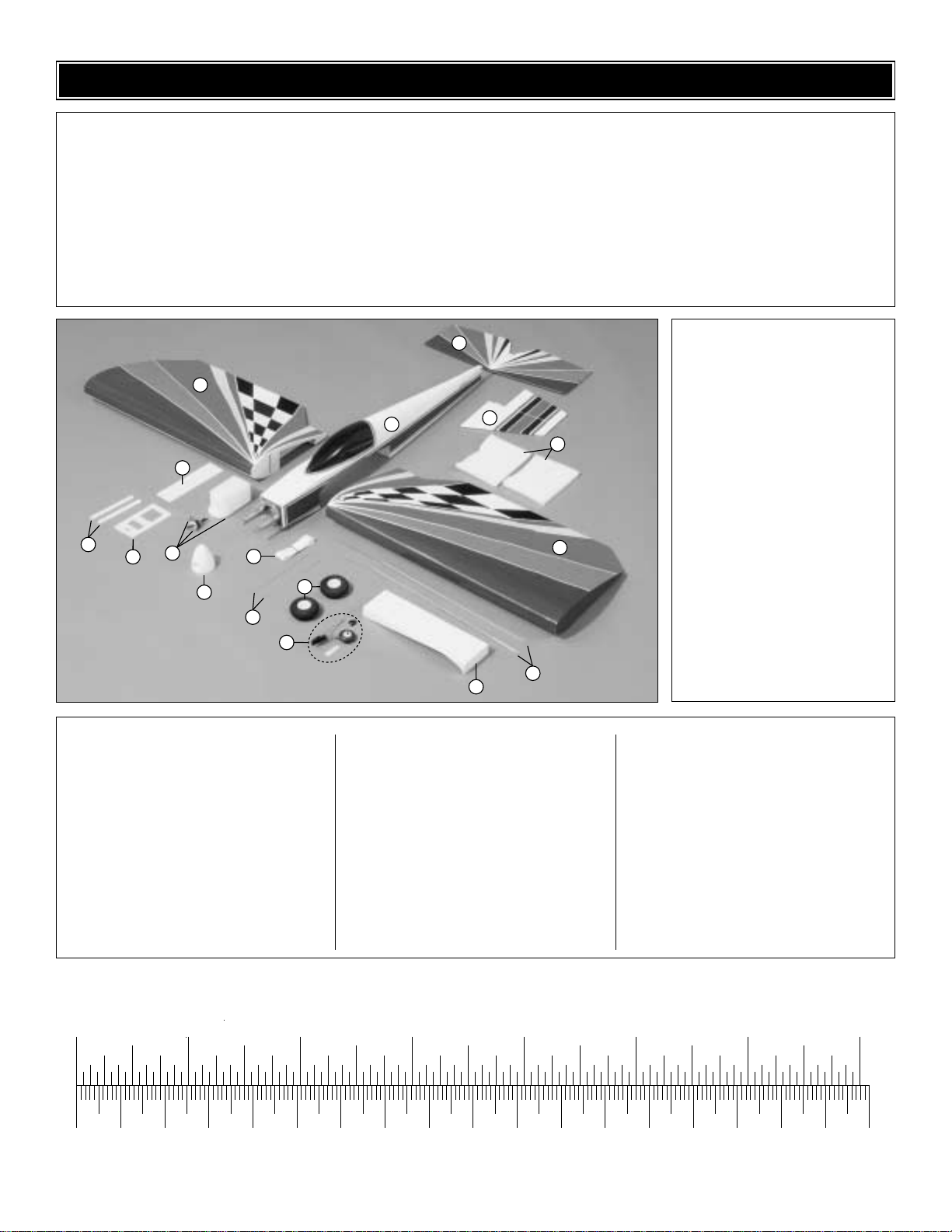
4
1 Wing
2 Fuselage
3 Stab
4 Fin
5 Fuel T ank Assembly
6 Spinner
7 Wing T ape
8 Pushrods
9 Aileron Pushrods
10 Main Wheels (2)
11 Tailwheel Assembly
12 Servo Tray
13 Wing Joiner
14 Servo Tray Mounting Rails
15 Radio Compartment Cover
16 Foam Rubber
(2) .074 x 36" pushrod wire, threaded one end
(elevator, rudder)
(2) .074 x 6" pushrod wire, threaded one end (aileron)
(4) Large control horn (elevator/rudder/aileron)
(8) 2-56 x 1/2" machine screws (elev/rudder/ail)
(4) Nylon clevises (elevator/rudder/(2)aileron)
(4) Nylon Faslink (elevator/rudder/(2)aileron)
(4) 5/32" wheel collar (for main landing gear)
(4) 6-32 set screw (for the wheel collars)
(4) Silicone clevis retainers (elevator/rudder/(2)aileron)
(17) 2 x 1/2" sheet metal screws (L.G. straps, battery
compartment, tail wheel bracket)
(2) Screw lock connector (throttle linkage)
(2) Nylon retainer (throttle linkage)
(2) 4-40 x 1/4" Socket head cap screw (throttle linkage)
(1) Wire cable .056 x 36" (throttle linkage)
(1) Plastic tube (throttle linkage)
(4) Nylon hump landing gear strap (landing gear)
(4) 3mm x 20mm bolts (Pre-installed for engine mount)
(4) 3mm washer (Pre-installed for engine mount)
(4) 3mm lock washer (Pre-installed for engine mount)
(4) 3mm blind nut (Pre-installed for engine mount)
(4) 1mm screws (Pre -installed in fuel tank hatch)
(2) Aluminum straps (mounting engine to engine mount)
(4) 8/32 bolts (for mounting engine to the engine
mounting straps and engine mount)
(8) 8-32 nuts (for mounting engine to the engine
mounting straps and engine mount)
(4) 8-32 lock washers (for mounting engine to the
engine mounting straps and engine mount)
(2) 1mm machine screws (tailwheel bracket)
(1) 1mm wheel collar (retains tailwheel)
(1) 2mm allen set screw (for wheel collar)
(4) 1/4" x 9/16" x 9/16" wood block
(6) wooden triangle gussets
(4) Nylon straps (mounting belly pan)
(1) Main landing gear
(2) Outer pushrod tubes (installed)
(1) Decal sheet
Kit Contents (Not Photographed)
Kit Contents
(Photographed)
KIT CONTENTS
To convert inches to millimeters, multiply inches by 25.4
Before starting to build, use the Kit Contents list to take an inventory of this kit to make sure it is complete and inspect
the parts to make sure they are of acceptable quality. If any parts are missing or are not of acceptable quality, or if you
need assistance with assembly, contact Great Planes Product Support.When reporting defective or missing parts, use
the part names exactly as they are written in the Kit Contents list on this page.
3002 N. Apollo Drive, Suite 1
Champaign, IL 61822
Telephone: (217) 398-8970
Fax: (217) 398-7721
E-mail: airsupport@greatplanes.com
1
13
14
5
12
6
7
10
9
11
3
2
4
16
1
8
15
Inch Scale
0" 1" 2" 3" 4" 5" 6" 7"
0 10 20 30 40 50 60 70 80 90 100 110 120 130 140 150 160 170 180
Metric Scale
Page 5
❏ 1.Locate the left and right Wing Panel and Wing Joiner.
Test fit the two wing halves to the wing joiner. Once you are
satisfied with the fit, glue the wing joiner into the right wing
panel with 6-minute epoxy.Set it aside to cure. Note: Be sure
to remove any epoxy that squeezes out before it cures.
❏ 2. After the glue has cured, apply 6-minute epoxy to the
other end of the joiner and the root ribs. Press the two wing
halves together. Use masking tape to hold the two wings
together while the glue cures.
❏ 3. After the glue has cured apply the self adhesive wing
tape to the wing joint.
❏ 1. Trim away the covering on the wing saddle.
❏ 2. Locate six triangle wood blocks. Glue them in place
on the inside of the fuselage flush with the wing saddle in the
locations shown in the photograph.
(These blocks provide
additional surface area when we glue the wing to the
fuselage. Placement is not critical as long as three are
placed on each side)
.
❏ 3. Place masking tape on the fuselage, one piece ahead
of the wing saddle and one piece behind the wing saddle.
Make a mark on each piece of tape exactly at the center of
the fuselage.
WING INSTALLATIONWING ASSEMBLY
5
Page 6
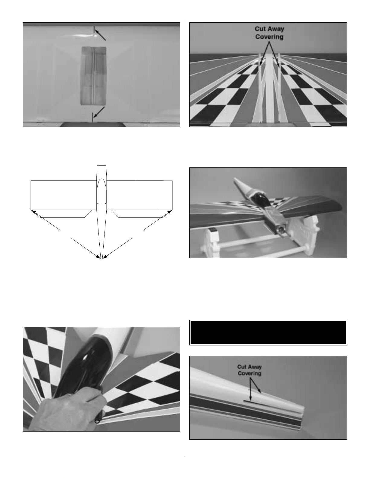
❏ 4. Make a mark on the center of the wing at the leading
and trailing edge.
❏ 5.Place the wing on the fuselage, aligning the marks you
made on the fuse and wing. Measure from the aft center of
the fuselage to one wing tip and record the distance.
Measure from the same point to the opposite wing tip and
compare it to the first measurement. If the measurements
are not the same, adjust the wig and re-measure until they
are equal.
❏ 6.Once the wing is properly positioned, turn the wing and
fuselage over and mark the location of the fuselage on the
top of the wing.
❏ 7. Cut away a 1/2" [13mm] strip of the film from the wing.
Be sure the cut is inside of the line. Important: Use only
enough pressure to cut through the film. Cutting into the
wing sheeting will weaken the strength of the wing.
❏ 8. Block the wing up off of the bench. Apply 6-minute
epoxy onto the wood where the covering has been cut away
and to the wood blocks. Place the fuselage onto the wing.
Place weight (bags of lead shot work well) onto the fuselage
to hold it in place on the wing and let the glue cure.
❏ 1.Cut away the covering from the openings in the fuselage
for the stab and fin.
INST ALL THE ST ABILIZER
AND ELEVATOR
A
A
A = A
6
Page 7

❏ 2.Slide the stabilizer into the fuselage.Center the stabilizer
in the fuselage by measuring the distance from the center of
the fuselage to the tip of the stabilizer. The stabilizer is
centered when the measurements from both sides are equal.
❏ 3.Align the stab by measuring from the wing tip back to the
tip of the stabilizer.Do this until both sides are equally spaced.
❏ 4.With the stab in place, stand back 8 – 10 feet [2.5 – 3
meters] and view the model from the front and rear .The stab
tips should be equally spaced below the level of the wing. If
not, lightly sand the high side of the stab saddle to correct
the problem.Work slowly and check the alignment often.
❏ 5.When you are satisfied with the position of the stab, use
a felt-tip pen to mark the sides of the fuselage on the bottom
and top of the stab.Remove the stab from the fuselage.
❏ 6. Use a fresh #11 blade to carefully cut through the
covering inside the lines you marked on the bottom and top
of the stab that indicate the fuse sides.Do not cut the wood
under the covering! This will weaken the structure and
may cause the stab to fail in flight. Remove the covering
from the center of the stab within the lines you cut.
❏ 7. Use a liberal coating of 30-minute epoxy to glue the
stab in position. Double check the alignment with the wing
and fuse while the epoxy cures.
A
A
A = A
B
B
B = B
7
Page 8

❏ 1. If you haven't already cut away the covering in the slot
where the fin and rudder assembly are installed, do so now.
❏ 2. Slide the fin into the slot. Make a mark on the end of
the fuselage where the hinge from the rudder needs to slide
into the fuselage.
❏ 3. The pre-cut slot in the fuselage for the rudder hinge
may be a bit tight for the hinge .With a #11 knife blade, widen
the slot until the hinge fits the slot with enough room to be
able to get epoxy in the slot with the hinge. Test fit the fin
onto the fuselage, making sure the hinge fits into the slot.
❏ 4. Use a felt tip-pen to mark the sides of the fin where it
meets the fuselage.
❏ 5. Cut the covering away from the fin inside the lines you
just made, being careful not to cut into the wood. Remove
any film that may be on the bottom of the fin where the
bottom of the fin makes contact with the fuselage.
❏ 6. Apply a small amount of petroleum jelly or small drop
of oil onto the joint of the hinge. This will prevent the glue
from getting into the hinge when gluing it to the fuselage.
❏ 7. Apply a liberal amount of 30-minute epoxy to the fin
and the hinge.Put the fin assembly in place on the fuselage.
❏ 8.Use a triangle to make certain that the fin is exactly 90°
to the stab. Use masking tape to hold the fin in position to
the stab while the glue cures.
❏ 1.Determine the position for the throttle linkage that best
suits the engine you are installing.We used the O.S. 40 LA.
Determine which hole in the corner of the firewall best fits
your engine, then insert the plastic outer pushrod to pass
through it.
❏ 2. Install the outer plastic pushrod through the fuel tank
compartment and under the wing. Do not glue the pushrod
in place yet!
ENGINE INSTALLATION
90˚
90˚
INSTALL THE FIN AND RUDDER
8
Page 9

❏ 3. Locate the two aluminum engine mount straps, four
8-32 x 1" bolts, four #8 lock washer and eight #8 nuts.
❏ 4. Position the engine in place on the engine mount.
Place the engine mount strap on each side of the engine.
❏ 5. Attach the engine to the mount by using the 8-32 bolts,
#8 lock washer and one #8 nut per bolt.When installing the
engine it is important that the crankshaft be 90 degrees to the
firewall.Once the engine is firmly bolted to the mount, attach
a second #8 nut to the bolt. This double-nut installation will
prevent the bolt and nut from vibrating loose.
❏ 6. Be sure the outer plastic pushrod extends through the
firewall 1-3/4" [44mm], then glue it in place to the firewall.
❏ 7.Install the braided cable into the outer plastic pushrod.
❏ 8. Attach the cable to the throttle barrel with the screw
lock connector as shown above.
❏ 1.Locate the fuel stopper assembly.Assemble it as shown.
❏ 2.Bend one of the two plastic tubes as shown.The tube with
the bend is the vent line, the straight one is for the fuel pickup.
❏ 3. Complete the fuel tank assembly as shown. The final
step, once the assembly is inserted into the tank, is to
tighten the screw a few turns to pull the rubber stopper
against the wall of the fuel tank.
❏ 4. Remove the hatch to the fuel tank compartment.
Fuel Stopper
Assembly
To Muffler
To Carburetor
Fuel Line
Fuel Clunk
FUEL T ANK INST ALLA TION
9
4-40 x 1/4" SHCS
RETAINER
Page 10

❏ 5. Cut a piece of foam the size of the bottom of the fuel
tank.Place this foam inside the fuel tank compartment.Then
insert the tank into the fuel tank compar tment.
❏ 6. Attach a piece of silicone fuel tubing to each of the fuel
tank fittings. Pass the lines through the hole in the firewall.
Connect the lines to the engine.The line attached to the fuel
clunk attaches to the carburetor and the other to the pressure
fitting on the muffler. Note: Refer to the sketch at Step 3 to
see exact fuel line connection.
❏ 7. Cut another piece of foam and place it on top of the fuel
tank, then reinstall the fuel compartment hatch to the fuselage.
❏ 1.Cut away the covering in the wing to re veal the openings
for the two servos as shown in the above photograph.
❏ 2.Trial fit the servo tray into the opening in the bottom of
the wing.It should fit between the rib in each half of the wing.
Trim the tray as needed to fit into the wing.
❏ 2. Measure down from the surface of the wing 5/8"
[15.9mm]. On that mark draw a line that is parallel to the
bottom of the wing. Do this on the rib on both the right and
left wing panel.
❏ 3. Locate the two hardwood landing gear rails. Using
6-minute epoxy, glue the rails in place on the bottom of the
lines you have drawn.
❏ 4. After the glue has cured, glue the servo tray to the rails
with 6-minute epoxy.Be sure the side by side servo openings
in the tray match up with the two servo cutouts in the wing.
❏ 5. Install a 6" [150mm] ser vo extension onto the end of
two servos.(Hint:Tape the connectors together to insure the
extension does not unplug from the servo.)
❏ ❏ 6. Install one ser vo into the aileron servo bay in the
right wing, feeding the servo wire through the wing ribs,
exiting into the radio compartment.
❏ ❏ 7. Dr ill four 1/16" [1.6mm] holes in the servo mounting
tray for the ser vo screws. Note: Installing the screws without
drilling the holes may result in the plywood servo tray splitting.
RADIO INSTALLATION
10
Page 11

❏ ❏ 8. Install the ser vo using the hardware provided from
the radio manufacturer.
❏ ❏ 9. Repeat steps 6-8 for the left wing.
❏ 10. Install three servos into the servo tray using the
hardware provided by the manufacturer. Position the servos
as shown in the photograph.
❏ 11. The open area in front of the servo tray is where you
will locate the battery and receiver.Cut a piece of the foam
pad and fit it in the opening. Lay the battery on the foam. Cut
another piece of the foam pad and lay it on top of the battery,
then place the receiver on top of the foam. Optional:
Depending on the size of the battery and receiver you may
choose to put them on end, side by side.
❏ 12. Connect all of your servo leads into the receiver as
recommended by the radio manuf acturer .The aileron servos
can either be connected by a Y-harness or if you have a
computer radio with channel assignments you can plug
each servo into a separate channel. See your radio
instruction manual for the set-up procedure.
❏ 13. Locate the radio compartment cover. Measure
5-1/8" [128mm] from the back edge of the cover to wards the
center of the cover and make a mark.Draw a line across the
width of the cover. This is the center line for the switch and
charging jack installation. It is important that this line falls
between the servo tray and the cavity for the battery and
receiver or there may not be enough room f or the s witch and
charge jack. Before cutting the location for them, visually
check to be sure the line falls in the correct location.
❏ 14.Cut the openings and install the switch and charge jack.
❏ 15. Locate four 1/4" x 9/16" x 9/16" [6 x 14 x14mm]
hardwood blocks. Glue them in each corner on the inside
of the radio compartment cover.
❏ 16.Connect the battery to the switch harness and receiver.
11
Page 12

❏ 17. After the radio and battery have been installed it is
recommended that you place another small piece of foam on
top of the receiver and then hold the receiver in place with a
balsa stick (not included) as shown in the photograph.
❏ 18. Cut away the covering where the pushrods exit the
fuselage.Install the two 36" [900mm] solid wire pushrods into
the plastic outer pushrod tubes. Be sure the threaded end of
the pushrod exits at the rear of the fuselage.
❏ 19. Install a silicone clevis keeper onto the threaded end
of the rod. Install a clevis onto the threaded end of the rod
by turning the clevis onto the threads 14 turns.
❏ 20. Locate one of the nylon control horns and the control
horn mounting plate. Position the control horn on the left side
of the rudder, in line with the solid wire pushrod, centering the
control horn on the hinge line as shown in the above diagram.
❏ 21. Mark the location of the screw holes for the control
horn.Drill a hole through the marks with a 1/16" [1.6mm] drill.
❏ 22. Install the control horn with two 2-56 screws. The
screws should pass through the horn and the rudder, then
screw into the control horn mounting plate on the opposite
side of the rudder.
❏ 23. Attach the clevis to the outermost hole in the horn,
then slide the silicone retainer over the cle vis.Repeat this for
the elevator control horn.
❏ 24. Turn on your radio and receiver. Center the servos
and then install the servo arms as shown.
❏ 25. Center the elevator. Make a mark on the solid wire
pushrod where it lines up with the hole in the servo arm.
Make a 90-degree bend at the mark. Cut the rod above the
bend to a length of 3/16" [4.8mm].
❏ 26. Install the rod into the hole in the servo arm and then
attach a Faslink to hold the pushrod to the servo arm.
❏ 27.T urn on the transmitter and receiver.Set the throttle to
full open. Install the braided cable into the screw-lock
connector, then open the carburetor on your engine to full
open.Insert the screw-lock connector into the outermost hole
in the servo arm following the same installation instructions
as you used attaching the cable to the throttle barrel during
the engine installation. Cut the excess cable with a sharp
wire cutter.Turn off the radio system when this is completed.
FasLink
2-56 (.074") Pushrod Wire
Servo Horn
Correct
Hinge Line
Incorrect
12
Page 13

❏ 28. Cut unused arms from a leftover servo arm.
❏ 29. Drill a 1/16" [1.5mm] hole in bottom of the radio
compartment cover.
❏ 30. Use the ar ms to make a strain relief for the antenna
wire. After cutting the servo arms, thread the antenna
through the hole you drilled in the radio compartment cover
and attach the antenna to the vertical fin with a rubber band
and T-pin as shown above.
❏ ❏ 31.Turn on the receiver and radio to center the servos
for the ailerons.Install a servo arm onto the servo so that the
arm is parallel to the aileron.
❏ ❏ 32. Install a control horn onto the left aileron using the
same installation technique used for the elevator and rudder.
❏ ❏ 33.Locate one of the 6" [150mm] wire pushrods.Install
a silicone clevis keeper onto the wire then attach a clevis by
turning it onto the threaded end of the pushrod 14 turns.
❏ ❏ 34. Center the aileron. Make a mark on the solid wire
pushrod where it lines up with the outermost hole in the
servo arm. Make a 90-degree bend at the mark.Cut the rod
above the bend to a length of 3/16" [4.8mm].
❏ ❏ 35. Attach the pushrod to the aileron the same way it
was done for the elevator and rudder.
❏ 36 Repeat this procedure for the right aileron.
❏ 1. Turn the airplane upside down on your bench. Trial fit
the radio compartment cover in place on the wing.
❏ 2. Dr ill a 1/16" [1.6mm] hole in the corners of the cover,
drilling through the cover and the hardwood blocks you
glued in place earlier.
❏ 3. Attach a nylon strap with a #2 x 1/2" [13mm] screw at
each of the holes you drilled.
❏ 4. Position the straps so that they lay across the radio
compartment cover and the fuselage. Drill a hole in the
fuselage where each strap contacts the fuselage. Then
screw each strap to the fuselage.
INST ALLING THE RADIO
COMPARTMENT COVER
Cut Off
Unused
Arms
13
Page 14

❏ 1. Draw a center line on the bottom of the fuselage in
front of the wing L.E., beginning where the fuselage meets
the radio compartment cover.
❏ 2. Measure from the back edge of the fuselage forward
1-3/4" [44mm].Draw a line across the fuselage on this mark.
❏ 3. Locate the pre-bent wire landing g ear. Place the wire
on the fuselage over the reference lines you have drawn,
aligning the center of the bend in the wire on the center line
of the fuselage.
❏ 4. Locate four humped nylon landing gear straps. Drill
1/16" holes in the fuselage for the straps, then screw them
in place as shown in the photograph using the #2 x 1/2"
[13mm] sheet metal screws.
❏ ❏ 5. Locate four 5/32" [4mm] wheel collars. Insert a
6-32 set screw into each one. Place one wheel collar onto
the main landing gear wire. Lock it in place onto the wire 1"
[25mm] from the end of the wire.
❏ ❏ 6. Insert a foam wheel onto the wire followed by
another wheel collar.Tighten the wheel collar in place on the
wire to lock the wheel in place. Hint: The wheel collar will
tighten better to the wire if you file a small flat spot where the
set screw contacts the wire.
❏ 7. Repeat this for the remaining wheel.
❏ 8. Locate the plywood mounting plate for the tailwheel
assembly. Place it on the bottom of the aft end of the
fuselage. Use a felt tip pen to mark the location of the plate
on the fuselage.
❏ 9. Cut away the covering inside of the lines you have
drawn. Then glue the plywood plate to the fuselage with
6-minute epoxy.
❏ 10. When the glue has cured, place the tailwheel
assembly in place on the plywood plate. Mark the locations
of the mounting holes. With a 3/64" [1.2mm] drill bit, drill
through the marks on the plywood plate.
INSTALLING THE LANDING GEAR
14
Page 15

❏ 11. Screw the tailwheel assembly to the plate.
❏ 12. Locate the plastic tailwheel bracket. Slide it onto the
wire, then press it firmly onto the rudder. Once in place drill
a 1/16" [1.6mm] hole into the rudder. Secure the bracket to
the rudder with a #2 x 1/2" [13mm] sheet metal screw.
❏ 1.Install the spinner and the propeller appropriate for your
choice of engine.
By moving the position of the clevis at the control horn
toward the outermost hole, you will decrease the amount of
throw of the control surface. Moving it toward the control
surface will increase the amount of throw. If these
adjustments don't accomplish the job, you ma y need to w ork
with a combination of adjustments by also repositioning the
pushrod at the servo end. Moving the pushrod towards the
center of the servo horn will decrease the control surface
throw – outward will increase it.
Note: Throws are measured at the widest part of the
elevators , rudder and ailerons.We recommend the following
control surface throws as a starting point:
Low Rate High Rate
ELEVATOR: 3/8" [9.5mm] up 1/2" [13mm] up
3/8" [9.5mm] down 1/2" [13mm] down
RUDDER: 1-1/4" [32mm] right Same
1-1/4" [32mm] left Same
AILERONS: 3/8" [9.5mm] up 3/4" [19mm] up
3/8" [9.5mm] down 3/4" [19mm] down
One leading cause of crashes is flying an airplane with its
control throws set differently from those recommended in the
instructions. The Great Planes AccuThrow™GPMR2405 lets
you quickly and easily measure actual throws first, so you can
make necessary corrections before you fly.Large, no-slip rubber
feet provide a firm grip on covered surfaces without denting or
marring the finish. Spring tension holds AccuThrow's plastic
ruler steady by each control surface. Curved to match control
motions, the ruler provides exact readings in both standard or
metric measurements.
Control Surface Throws
Control Thro w Adjustment
FINAL ASSEMBLY
15
Page 16

Make sure the control surfaces move in the proper direction as
illustrated in the above sketch.
Note:This section is VERY important and must NOT be
omitted! A model that is not properly balanced will be
unstable and possibly unflyable.
❏ 1. The balance point (C.G.) is located 3" [75mm] back
from the leading edge of the wing. Balance your Dazzler
using a Great Planes C.G. Machine™Airplane Balancer
(GPMR2400) for the most accurate results. This is the
balance point at which your model should balance for your
first flights.After initial trim flights and when you become more
acquainted with your Dazzler, you may wish to experiment by
shifting the balance up to 1/4" [6mm] forward or backward to
change its flying characteristics. Moving the balance forward
may improv e the smoothness and stability, but the model may
then require more speed for takeoff and may become more
difficult to slow for landing.Moving the balance aft makes the
model more agile with a lighter, snappier “feel” and often
improves knife-edge capabilities. In any case, please start at
the location we recommend. Do not at any time balance your
model outside the recommended range.
❏ 2.With all parts of the model installed (ready to fly) and
an empty fuel tank, block up the tail as necessary to level the
stab.Lift the model at the desired balance point and observe
the tail of the aircraft. If the tail drops, the model is “tail
heavy” and you must add weight to the nose to balance the
model.If the nose drops, it is “nose hea vy”and you must add
weight* to the tail to balance the model.
Note: Nose weight may be easily installed by using a
“spinner weight.” Tail weight may be added by using Great
Planes (GPMQ4485) “stick-on” lead weights.
IMPORTANT: Do not confuse this procedure with “checking
the C.G.” or “balancing the air plane fore and aft.”
Now that you have the basic airplane nearly completed, this
is a good time to balance the airplane laterally (side-to-side).
Here is how to do it:
❏ 1. Make sure the fuel tank is empty.
❏ 2.With the wing level, lift the model by the engine propeller
shaft and the fin post (this may require two people). Do this
several times.
If one wing always drops when you lift the model, it means
that side is heavy. Balance the air plane by adding weight to
the opposite, lighter wing tip.
Note: An airplane that has been laterally balanced will track
better in loops and other maneuvers.
At this time check all connections including servo horn
screws, clevises, servo cords and extensions.
Follow the battery charging procedures in your radio
instruction manual.You should alwa ys charge your tr ansmitter
and receiver batteries the night before you go flying and at
other times as recommended by the radio manufacturer.
Charge the Batteries
PREFLIGHT
Balance Your Model Laterally
BALANCE Y OUR MODEL
CARBURETOR WIDE OPEN
RUDDER MOVES RIGHT
LEFT AILERON MOVES DOWN
RIGHT AILERON MOVES UP
ELEVATOR MOVES UP
4-CHANNEL
TRANSMITTER
(STANDARD MODE 2)
4-CHANNEL RADIO SETUP
TRANSMITTER
4-CHANNEL
TRANSMITTER
4-CHANNEL
TRANSMITTER
4-CHANNEL
16
Page 17

Carefully balance your propellers before flying.An unbalanced
prop is the single most significant cause of vibration. Not only
may engine mounting screws vibrate out, possibly with
disastrous effect, but vibration may also damage your radio
receiver and battery. Vibration may cause your fuel to foam,
which will, in turn, cause your engine to run lean or quit.
We use a Top Flite Precision Magnetic Prop Balancer
™
(TOPQ5700) in the workshop and keep a Great Planes
Fingertip Balancer (GPMQ5000) in our flight box.
We strongly suggest that the best place to fly is an AMA
chartered club field. Ask the AMA or your local hobby shop
dealer if there is a club in your area and join.Club fields are set
up for R/C flying and that makes your outing safer and more
enjoyable.The AMA address and telephone number are in the
front of this manual. If a club and flying site are not available,
find a large, grassy area at least 6 miles away from houses,
buildings and streets and any other R/C radio operation lik e R/C
boats and R/C cars. A schoolyard may look inviting but is too
close to people, power lines and possible radio interference.
Inspect your radio installation and confirm that all the control
surfaces respond correctly to the transmitter inputs. The
engine operation must also be checked by confirming that the
engine idles reliably, transitions smoothly and rapidly to full
power and maintains full power, indefinitely. The engine must
be “broken-in”on the ground by running it for at least two tanks
of fuel.Follow the engine manuf acturer's recommendations f or
break-in. Make sure that all screws remain tight, that the
hinges are secure and that the prop is on tight.
Whenever y ou go to the flying field, check the operational r ange
of the radio before the first flight of the day.First, make sure no
one else is on your frequency (channel). With your transmitter
and receiver on , you should be able to walk at least 100 feet
away from the model and still have control.While you work the
controls, have a helper stand by your model and tell you what
the control surfaces are doing. Repeat this test with the engine
running at various speeds with a helper holding the model.If the
control surfaces are not always responding correctly, do not fly!
Find and correct the problem first. Look for loose servo
connections or corrosion, loose bolts that may cause vibration,
a defective on/off switch, low battery voltage or a defective
receiver battery, a damaged receiver antenna, or a receiver
crystal that may have been damaged from a previous crash.
Note: Failure to follow these safety precautions may result
in severe injury to yourself and others.
Keep all engine fuel in a safe place, away from high heat,
sparks or flames, as fuel is very flammable. Do not smoke
near the engine or fuel; and remember that the engine
exhaust gives off a great deal of deadly carbon monoxide.
Do not run the engine in a closed room or garage.
Get help from an experienced pilot when learning to
operate engines.
Use safety glasses when starting or running engines.Do not
run the engine in an area of loose gravel or sand; the
propeller may throw such material in your face or eyes.
Keep your f ace and body as well as all spectators a wa y from the
plane of rotation of the propeller as you start and run the engine.
Keep these items away from the prop: loose clothing, shir t
sleeves, ties, scarfs, long hair or loose objects such as
pencils or screwdrivers that may fall out of shirt or jacket
pockets into the prop.
Use a “chicken stick” or electric starter to star t the engine.
Do not use your fingers to flip the propeller .Make certain the
glow plug clip or connector is secure so that it will not pop
off or otherwise get into the running propeller.
Make all engine adjustments from behind the rotating propeller .
The engine gets hot! Do not touch it during or right after
operation. Make sure fuel lines are in good condition so fuel
will not leak onto a hot engine, causing a fire.
To stop a glow engine, cut off the fuel supply by closing off
the fuel line or following the engine manufacturer's
recommendations. Do not use hands, fingers or any other
body part to tr y to stop the engine. Do not throw anything
into the propeller of a running engine.
Engine Safety Precautions
Range Check Your Radio
Ground Check the Model
Find a Safe Place to Fly
Balance the Propeller
17
Page 18

Read and abide by the following Academy of Model
Aeronautics Official Safety Code:
General
1.I will not fly my model aircraft in sanctioned e vents, air sho ws,
or model flying demonstrations until it has been proven to be
airworthy by having been previously successfully flight tested.
2. I will not fly my model aircraft higher than approximately
400 feet within 3 miles of an airport without notifying the
airpor t operator. I will give right of way to and avoid flying in
the proximity of full-scale aircraft. Where necessary an
observer shall be used to supervise flying to avoid having
models fly in the proximity of full-scale aircraft.
3. Where established, I will abide by the safely rules for the
flying site I use and I will not willfully and deliberately fly my
models in a careless, reckless and/or dangerous manner.
4. I will not fly my model unless it is identified with my name
and address or AMA number, on or in the model.
5. I will not operate models with pyrotechnics (any device
that explodes, burns, or propels a projectile or any kind).
Radio Control
1. I will have completed a successful radio equipment
ground check before the first flight of a new or repaired
model airplane.
2. I will not fly my model aircraft in the presence of
spectators until I become a qualified flier, unless assisted b y
an experienced helper.
3. I will perform my initial turn after takeoff away from the pit
or spectator areas and I will not thereafter fly over pit or
spectator areas, unless beyond my control.
4. I will operate my model using only radio control frequencies
currently allowed by the Federal Communications Commission.
The Dazzler is a very fun and enjoyable plane to fly. It is very
predictable when balanced at the recommended C.G. and
the control throws are set at the low rate recommendation.
Set up this way you will find that it performs most aerobatic
maneuvers with ease. Move the C.G. back and step up to
the high rate control throws and you will have a very
responsive, fun fly type of plane!
The Dazzler has no bad ground handling characteristics.
Simply line up on the runway, advance the throttle slowly,
make steering corrections as needed with the rudder and
you will be airborne in about 50 feet.
Once airborne you will find that the Dazzler performs slow
flight maneuvers as easily as it performs at faster speeds.
Tight loops, large loops, slow rolls, fast rolls, inverted flight
are all easily done with the Dazzler.Do you like to participate
in fun fly competitions? Try the limbo! You will be sur prised
how low and slow you can fly!
When it comes time to land the Dazzler, you will find it is as
predictable to land as it was to fly. Simply line it up on the
runway and slowly decrease the speed.When you are over
the runway, drop the throttle and flare to a three point landing!
Have a ball! But alwa ys sta y in control and fly in a safe manner .
Landing
CAUTION (THIS APPLIES TO ALL R/C AIRPLANES):
If, while flying, you notice any unusual sounds, such as a
low-pitched “buzz,” this may be an indication of control
surface “flutter.” Because flutter can quickly destroy
components of your airplane, any time you detect flutter you
must immediately cut the throttle and land the airplane!
Check all servo grommets for deterioration (this will indicate
which surface fluttered) and make sure all pushrod linkages
are slop-free. If it fluttered once, it will probably flutter again
under similar circumstances unless you can eliminate the
slop or flexing in the linkages. Here are some things which
can result in flutter: Excessive hinge gap; Not mounting
control horns solidly;Sloppy fit of clevis pin in horn;Elasticity
present in flexible plastic pushrods; Side-play of pushrod in
guide tube caused by tight bends; Sloppy fit of Z-bend in
servo arm; Insufficient glue used when gluing in the elevator
joiner wire or aileron torque rod;Excessive flexing of aileron,
caused by using too soft balsa aileron; Excessive “play” or
“backlash” in servo gears; and Insecure servo mounting.
Flying
Takeoff
FLYING
AMA SAFETY CODE (excerpt)
18
Page 19

APPENDIX
FLIGHT TRIMMING
Note: The following article has been reprinted in part for future reference
and also as a guide for your flight instructor or experienced flying partner to
help you with trimming your model.If further information is required, please
contact your local hobby dealer, local flying club or call Great Planes at
(217) 398-8970
A model is not a static object.Unlike a car, which you can only hunt left
or right on the road (technically , a car does y aw in corners and pitches when
the brakes are applied), a plane moves through that fluid we call air in all
directions simultaneously. The plane may look like it's going forward, but it
could also be yawing slightly, slipping a little and simultaneously climbing or
diving a bit! The controls interact. Yaw can be a rudder problem, a lateral
balance problem or an aileron rigging problem.We must make many flights,
with minor changes between each, to isolate and finally correct the problem.
The chart accompanying this article is intended to ser ve as a handy
field reference when trimming your model.Laminate it in plastic and keep it
in you flight box. You just might have need to consult it at the next contest!
The chart is somewhat self-explanatory, but we will briefly run through the
salient points.
First, we are assuming that the model has been C.G. balanced
according to the manufacturer's directions. There's nothing sacred about
that spot — frankly, it only reflects the balance point where a prototype
model handled the way the guy who designed it thought it should. If your
model's wing has a degree more or less of incidence, then the whole
balance formula is incorrect for you.But, it's a good ballpark place to start.
The second assumption is that the model has been balanced laterally.
Wrap a strong string or monofilament around the prop shaft behind the
spinner, then tie the other end to the tail wheel or to a screw driven into the
bottom of the aft fuse. Make the string into a bridle harness and suspend
the entire model inverted (yes, with the wing on!). If the right wing always
drops, sink some screws or lead into the left wing tip, etc. You may be
surprised to find out how much lead is needed.
At this point the model is statically trimmed. It's only a starting point, so
don't be surprised if you wind up changing it all. One other critical feature is
that the ailerons must have their hinge gap sealed.If shoving some Scotch
tape or Monokote into the hinge gap to prevent the air from slipping from the
top of the wing to the bottom and vice-versa, bothers you, then don't do it.
To achieve the maximum lateral trim on the model, the hinge gap on
the ailerons should be sealed. The easiest way to do this is to disconnect
the aileron linkages and fold the ailerons as far over the top of the wing as
possible (assuming they are top or center hinged). Apply a str ip of clear
tape along the joint line. When the aileron is returned to neutral, the tape
will be invisible and the gap will be effectively sealed. Depending on how
big the ailerons are and how large a gaping gap you normally leave when
you install hinges, you could experience a 20 percent increase in aileron
control response just by this simple measure.
Your first flights should be to as certain control centering and control
feel.Does the elevator always come bac k to neutral after a 180° turn or SplitS? Do the ailerons tend to hunt a little after a rolling maneuver? Put the
plane through its paces. Control centering is either a mechanical thing
(binding servos, stiff linkages, etc.), an electronic thing (bad servo resolution
or dead band in the radio system), or C.G. (aft Center of Gravity will make
the plane wander a bit).The last possibility will be obvious, but don't continue
the testing until you have isolated the problem and corrected it.
Let's get down to the task of trimming the model.Use the tachometer every
time you start the engine, to insure consistent results.These trim flights must be
done in calm weather.Any wind will only make the model weather vane. Each
“maneuver”on the list assumes that you will enter it dead straight-and-level.The
wings must be perfectly flat, or else the maneuver will not be correct and you'll
get a wrong interpretation.That's where your observer comes in. Instruct him to
be especially watchful of the wings as you enter the maneuvers.
Do all maneuvers at full throttle.The only deviation from this is if the
plane will routinely be flown through maneuvers at a different po wer setting.
Let's commence with the “engine thrust angle” on the chart. Note that
the observations you make can also be caused by the C .G., so be prepared
to change both to see which gives the desired result.Set up a straight-andlevel pass. The model should be almost hands-off. Without touching any
other control on the transmitter, suddenly chop the throttle. Did the nose
drop? When you add power again, did the nose pitch up a bit? If so, you
need some down thrust, or nose weight. When the thr ust is correct, the
model should continue along the same flight path for at least a dozen plane
lengths before gravity starts to naturally bring it down.
Do each maneuver several times, to make sure that you are getting a
proper diagnosis.Often, a gust, an accidental nudge on the controls, or just
a poor maneuver entry can mislead you.The thrust adjustments are a real
pain to make. On most models, it means taking the engine out, adding
shims, then reassembling the whole thing.Don't take shortcuts.
Don't try to proceed with the other adjustments until you have the
thrust line and/or C.G. correct.They are the basis upon which all other trim
settings are made.
Also, while you have landed, take the time to crank the clevises until
the transmitter trims are at neutral. Don't leave the airplane so that the
transmitter has some odd-ball combination of trim settings. One bump of
the transmitter and you have lost everything. The trim must be repeatable
and the only sure way to do this is to always start with the transmitter
control trims at the middle.
The next maneuver is somewhat more tricky than it looks. To verify
C.G., we roll the model up to a 45° bank, then take our hands off the
controls. The model should go a reasonable distance with the fuse at an
even keel. If the nose pitches down, remove some nose weight and the
opposite if the nose pitches up.The tr ick is to use only the ailerons to get
the model up at a 45° bank. We almost automatically start feeding in
elevator , b ut that's a no-no .Do the bank in both directions, just to make sure
that you are getting an accurate reading of the longitudinal balance.
We now want to test the correct alignment of both sides of the ele v ator
(even if they aren't split, like a Pattern ship's, they can still be warped or
twisted).Yaw and lateral balance will also come into pla y here, so be patient
and eliminate the variables, one-by-one.The maneuver is a simple loop, but
it must be entered with the wings perfectly level. Position the maneuver so
that your assistant can observe it end-on. Always loop into the wind. Do
several loops and see if the same symptom persists.Note if the model loses
heading on the front or back side of the loop. If you lose it on the way up,
it's probably an aileron problem, while a lose of heading on the way back
down is most likely a rudder situation.
Note that the Yaw test is the same looping sequences. Here, however,
we are altering rudder and ailerons, instead of the elevator halves .We must
repeat that many airplanes just will not achieve adequate lateral trim
without sealing the hinge gaps shut. The larger you make the loops (to a
point), the more discernable the errors will be.
The Lateral Balance test has us pulling those loops very tightly. Pull
straight up into a vertical and watch which wing drops.A true vertical is hard
to do, so make sure that your assistant is observing from another vantage
point. Note that the engine torque will affect the vertical fall off, as will
rudder errors.Even though we balance the wing statically before leaving for
the field, we are now trimming it dynamically.
The Aileron Coupling (or rigging), is also tested by doing Hammerheads
Stalls. This time, however, we want to observe the side view of the model.
Does the plane want to tuck under a bit? If so, then try trimming the ailerons
down a small bit, so that they will act as flaps. If the model tends to want to
go over into a loop, then rig both ailerons up a f e w turns on the clevises .Note
that drooping the ailerons will tend to cancel any washout you have in the
wing. On some models, the lack of washout can lead to some nasty
characteristics at low speeds.
Again, we reiterate that all of these controls are interactive.When you
change the wing incidence, it will influence the way the elevator trim is at a
given C.G. Re-trimming the wing will also change the rigging on the
ailerons, in effect and they may have to be readjusted accordingly.
The whole process isn't hard. As a matter of fact it's rather fun — but
very time consuming. It's amazing what you will learn about why a plane flies
the way it does and you'll be a better pilot for it. One thing we almost
guarantee, is that your planes will be more reliable and predictab le when they
are properly trimmed out. They will fly more efficiently and be less prone to
doing radical and surprising things.Your contest scores should improve, too.
We wish to acknowledge the Orlando, Florida, club newsletter, from
which the basics of the chart presented here were gleaned.
Reprinted in part by Great Planes Model Manufacturing Company,
courtesy of Scale R/C Modeler magazine, Pat Potega, Editor, August
1983 issue.
See the Flight Trimming Chart on the back cover.
19
Page 20

TRIM FEATURE
MANEUVERS OBSERVATIONS CORRECTIONS
CONTROL
CENTERING
CONTROL
THROWS
ENGINE
THRUST
ANGLE
1
CENTER OF
GRAVITY
LONGITUDINAL
BALANCE
YAW
2
LATERAL
BALANCE
AILERON
RIGGING
Fly general circles and
random maneuvers.
Random maneuvers
From straight flight,
chop throttle quickly.
From level flight roll to
45º bank and
neutralize controls.
Into wind, do open loops,
using only elevator.
Repeat tests doing
outside loops from
inverted entry.
Into wind, do tight inside
loops.
With wings level, pull
to vertical climb and
neutralize controls.
Try for hands off straight
and level flight.
A.Too sensitive, jerky
controls.
B. Not sufficient control.
A. Aircraft continues level
path for short distance.
B. Plane pitches nose up.
C.Plane pitches nose
down.
A. Continues in bank for
moderate distance.
B. Nose pitches up.
C. Nose drops.
A.Wings are level
throughout.
B.Yaws to right in both
inside and outside
loops.
C.Yaws to left in both
inside and outside
loops.
D. Yaws right on insides,
and left on outside
loops.
E.Yaws left in insides,
and right on outside
loops.
A.Wings are level and
plane falls to either
side randomly.
B. Falls off to left in loops.
Worsens as loops
tighten.
C.Falls off to right in
loops.Worsens as
loops tighten.
A. Climb continues along
same path.
B. Nose tends to go to
inside loop.
C.Nose tends to go to
outside loop.
Readjust linkages so that
Tx trims are centered.
If A, change linkages to
reduce throws.
If B, increase throws.
If A, trim is okay.
If B, decrease downthrust.
If C, increase downthrust.
If A, trim is good.
If B, add nose weight.
If C, remove nose weight.
If A, trim is correct.
If B, add left rudder trim.
If C, add right rudder trim.
If D, add left aileron trim.
If E, add right aileron trim.
If A, trim is correct.
If B, add weight to right
wing tip.
If C, add weight to left
wing tip.
If A, trim is correct.
If B, raise both ailerons
very slightly.
If C, lower both ailerons
very slightly.
1. Engine thrust angle and C.G. interact. Check both.
2.Yaw and lateral balance produce similar symptoms.Note that fin may be crooked.Right and left references are from the plane’s vantage point.
 Loading...