

Great Planes GPMA1036 User Manual

WARRANTY
Great Planes Model Manufacturing Co. guarantees this kit to be free from defects in both material and
workmanship at the date of purchase. This warranty does not cover any component parts damaged by use or
modification. In no case shall Great Planes' liability exceed the original cost of the purchased kit. Further, Great
Planes reserves the right to change or modify this warranty without notice.
In that Great Planes has no control over the final assembly or material used for final assembly, no liability shall be
assumed nor accepted for any damage resulting from the use by the user of the final user-assembled product. By the
act of using the user-assembled product, the user accepts all resulting liability.
If the buyers are not prepared to accept the liability associated with the use of this product, they are advised
to return this kit immediately in new and unused condition to the place of purchase.
READ THROUGH THIS INSTRUCTION MANUAL
FIRST. IT CONTAINS IMPORTANT INSTRUCTIONS
AND WARNINGS CONCERNING THE ASSEMBLY
AND USE OF THIS MODEL.
ES03 V2.0 Entire Contents © Copyright 2002
1610 Interstate Drive, Champaign, IL 61822
(217) 398-8970, Ext 2
airsupport@greatplanes.com
INSTRUCTION MANUAL
TM
Length: 50" [1270mm] Weight: 5.5 - 6.5 lbs [2495 - 2948g]
Wingspan: 58.75" [1492mm] Wing Area: 742 sq in [ 47.9sq cm]
Wing Loading: 17.1 - 20.2 oz/sq ft [52.2 - 61.6 g/sq cm]
Radio: 4-ch (4 servos)
Engine: .40 - .51 two-stroke [6.5 - 8.4cc 2-stroke]
.52 - .70 four-stroke [8.5 - 11.5cc 4-stroke]
MADE IN
USA

INTRODUCTION . . . . . . . . . . . . . . . . . . . . . . . . . . . . . . . . .
SAFETY PRECAUTIONS . . . . . . . . . . . . . . . . . . . . . . . . . .
DECISIONS YOU MUST MAKE . . . . . . . . . . . . . . . . . . . . .
Engine Recommendations . . . . . . . . . . . . . . . . . . . . . . .
ADDITIONAL ITEMS REQUIRED . . . . . . . . . . . . . . . . . . .
Radio Equipment . . . . . . . . . . . . . . . . . . . . . . . . . . . . . .
Hardware and Accessories . . . . . . . . . . . . . . . . . . . . . .
Adhesives and Building Supplies . . . . . . . . . . . . . . . . . .
Optional Supplies and Tools . . . . . . . . . . . . . . . . . . . . . .
IMPORTANT BUILDING NOTES . . . . . . . . . . . . . . . . . . . .
COMMON ABBREVIATIONS . . . . . . . . . . . . . . . . . . . . . . .
KIT CONTENTS . . . . . . . . . . . . . . . . . . . . . . . . . . . . . . . . .
ORDERING REPLACEMENT PARTS . . . . . . . . . . . . . . . .
BUILDING INSTRUCTIONS . . . . . . . . . . . . . . . . . . . . . . . .
WING ASSEMBLY . . . . . . . . . . . . . . . . . . . . . . . . . . . . . . .
Assemble the Wing Joiners . . . . . . . . . . . . . . . . . . . . . .
Join the Wing Panels . . . . . . . . . . . . . . . . . . . . . . . . . . .
Install the Aileron Servo Tray . . . . . . . . . . . . . . . . . . . . .
Install the Wing Bolt Plate . . . . . . . . . . . . . . . . . . . . . . .
INSTALL FUSELAGE COMPONENTS . . . . . . . . . . . . . . .
Install the Engine . . . . . . . . . . . . . . . . . . . . . . . . . . . . . .
Install the Pushrod Tubes . . . . . . . . . . . . . . . . . . . . . . . .
Assemble the Fuel Tank . . . . . . . . . . . . . . . . . . . . . . . . .
Complete the Engine & Fuel Tank Installation . . . . . . . .
MOUNT THE WING TO THE FUSELAGE . . . . . . . . . . . . . .
Mount the Wing to the Fuselage . . . . . . . . . . . . . . . . . .
INSTALL THE TAIL COMPONENTS . . . . . . . . . . . . . . . . .
Join the Elevator Halves . . . . . . . . . . . . . . . . . . . . . . . . .
Align & Install the Stabilizer . . . . . . . . . . . . . . . . . . . . . .
Install the Vertical Fin . . . . . . . . . . . . . . . . . . . . . . . . . . .
Install the Hinges . . . . . . . . . . . . . . . . . . . . . . . . . . . . . .
INSTALL THE LANDING GEAR . . . . . . . . . . . . . . . . . . . . .
Mount the Main Landing Gear . . . . . . . . . . . . . . . . . . . .
Mount the Nose Gear . . . . . . . . . . . . . . . . . . . . . . . . . . .
RADIO INSTALLATION . . . . . . . . . . . . . . . . . . . . . . . . . . .
Install the Radio Components . . . . . . . . . . . . . . . . . . . .
Install the Pushrods & Control Horns . . . . . . . . . . . . . . .
FINAL ASSEMBLY . . . . . . . . . . . . . . . . . . . . . . . . . . . . . . .
Install the Wheels . . . . . . . . . . . . . . . . . . . . . . . . . . . . . .
Install the Canopy . . . . . . . . . . . . . . . . . . . . . . . . . . . . .
GET THE MODEL READY TO FLY . . . . . . . . . . . . . . . . . .
Check the Control Directions . . . . . . . . . . . . . . . . . . . . .
Set the Control Throws . . . . . . . . . . . . . . . . . . . . . . . . .
Balance the Model (C.G.) . . . . . . . . . . . . . . . . . . . . . . . .
Balance the Model Laterally . . . . . . . . . . . . . . . . . . . . . .
PREFLIGHT . . . . . . . . . . . . . . . . . . . . . . . . . . . . . . . . . . . .
ENGINE SAFETY PRECAUTIONS . . . . . . . . . . . . . . . . . .
AMA SAFETY CODE . . . . . . . . . . . . . . . . . . . . . . . . . . . . .
IMAA SAFETY CODE . . . . . . . . . . . . . . . . . . . . . . . . . . . .
CHECK LIST . . . . . . . . . . . . . . . . . . . . . . . . . . . . . . . . . . . .
FLYING . . . . . . . . . . . . . . . . . . . . . . . . . . . . . . . . . . . . . . . .
Takeoff . . . . . . . . . . . . . . . . . . . . . . . . . . . . . . . . . . . . . .
Flight . . . . . . . . . . . . . . . . . . . . . . . . . . . . . . . . . . . . . . .
Landing . . . . . . . . . . . . . . . . . . . . . . . . . . . . . . . . . . . . .
Congratulations and thank you for purchasing the Great
Planes Easy Sport 40 ARF, with MonoKote covering! This
model has many features that are usually found only in kittype aircraft. These features include: rod-in-tube pushrods,
an adjustable glass-filled nylon engine mount, multiple color
covering and high quality Great Planes hardware. The
construction technique that is used for this aircraft results in
a model that is lighter and stronger than conventional, builtup balsa airplanes. The Easy Spor t 40 ARF will provide an
excellent second aircraft to help build confidence and assist
in perfecting your aerobatic skills.
The Great Planes Easy Sport 40 ARF is similar to the
original Easy Sport 40 kit. The Almost-Ready-to-Fly version
is stable enough to be a great second airplane, yet has
aerobatic capabilities which allows rapid advancement of
your aerobatic skills. This Easy Spor t has the same good
looks and excellent stability at low speeds that can be
found on the kit version and reflects the design expertise
and high quality standards of Great Planes kits.
For the latest technical updates or manual corrections to
the Easy Sport ARF visit the web site listed below and
select the Great Planes Easy Sport ARF. If there is new
technical information or changes to this model a “tech
notice” box will appear in the upper left corner of the page.
http://www.greatplanes.com/airplanes/index.html
1. Your Easy Sport ARF should not be considered a toy, but
rather a sophisticated, working model that functions very
much like a full-size airplane. Because of its performance
capabilities, the Easy Sport ARF, if not assembled and
operated correctly, could possibly cause injur y to yourself or
spectators and damage to property.
2. You must assemble the model according to the
instructions. Do not alter or modify the model, as doing so
may result in an unsafe or unflyable model. In a few cases
the instructions may differ slightly from the photos.In those
instances the written instructions should be considered
as correct.
3. You must take time to build straight, true and strong.
4. You must use an R/C radio system that is in first-class
condition, and a correctly sized engine and components
(fuel tank, wheels, etc.) throughout the building process.
5. You must correctly install all R/C and other components
so that the model operates correctly on the ground and in
the air.
PROTECT Y OUR MODEL,YOURSELF
& OTHERS...FOLLOW THIS
IMPORTANT SAFETY PRECAUTION
INTRODUCTIONTABLE OF CONTENTS
2
6. You must check the operation of the model before every
flight to insure that all equipment is operating and that the
model has remained structurally sound. Be sure to check
clevises or other connectors often and replace them if they
show any signs of wear or fatigue.
7. If you are not already an experienced R/C pilot, you
should fly the model only with the help of a competent,
experienced R/C pilot.
Remember: Take your time and follow the instructions to
end up with a well-built model that is straight and true.
If you have not flown this type of model before, we
recommend that you get the assistance of an
experienced pilot in your R/C club for your first flights.
You’ll learn faster and avoid risking your model before you
are truly ready to fly it. Your local hobby shop has
information about clubs in your area whose membership
includes experienced pilots.
In addition to joining an R/C club, we strongly recommend you
join the AMA (Academy of Model Aeronautics). AMA
membership is required to fly at AMA sanctioned clubs.There
are over 2,500 AMA chartered clubs across the country.
Among other benefits, the AMA provides insurance to its
members who fly at sanctioned sites and events. Additionally,
training programs and instructors are available at AMA club
sites to help you get started the right way. Contact the AMA at
the address or toll-free phone number below:
Academy of Model Aeronautics
5151 East Memorial Drive
Muncie, IN 47302-9252
Tele. (800) 435-9262
Fax (765) 741-0057
Or via the Internet at: http://www.modelaircraft.org
This is a partial list of items required to finish the Easy
Sport 40 ARF that may require planning or decision making
before starting to build.
❏ 4 Channel Radio with 4 Servos
This is the list of hardware and accessories required to
finish the Easy Sport ARF. Order numbers are provided
in parentheses.
❏ Muffler Extension (some engines) (OSMG2616 for
O.S..40 LA)
❏ Propellers (see engine instructions for sizes)
❏ 18” [457mm] Silicone fuel tubing (GPMQ4131)
❏ 1/4” [6.4mm] Latex foam rubber for receiver and
battery (HCAQ1000)
Note: Larger wheels than those included may be required
for operation on rough grass fields.
Hardware and Accessories
Radio Equipment
ADDITIONAL ITEMS REQUIRED
Engine Recommendations
The recommended engine size range for the Easy Sport
40 ARF is as follows:
.40 to .51 two-stroke
.52 to .70 four-stroke
The Easy Sport 40 ARF will fly well with any of the
recommended engine sizes. For “Hot Dogging” and
speedy performance, we suggest either an O.S..46 FX or
a SuperTigre GS-45, both 2-stroke engines. An O.S. FS70 Surpass II is a good choice for those who prefer
4-stroke engines.
DECISIONS YOU MUST MAKE
NOTE:We, as the kit manufacturer, can provide you with
a top quality kit and great instructions, but ultimately the
quality of your finished model depends on how you build
it; therefore, we cannot in any way guarantee the
performance of your completed model, and no
representations are expressed or implied as to the
performance or safety of your completed model.
3
In addition to common household tools and hobby tools,
this is the “short list” of the most important items required to
build the Easy Sport 40 ARF.
Great Planes Pro™ CA and
Epoxy glue are recommended.
❏ 1 oz.Thin Pro CA (GPMR6002)
❏ 1 oz. Medium Pro CA+ (GPMR6008)
❏ 6-Minute Epoxy (GPMR6045)
❏ 30-Minute Epoxy (GPMR6047)
❏ Hobby knife (HCAR0105)
❏ #11 blades (HCAR0211)
❏ Small T -pins (HCAR5100)
❏ Builder’s triangle (HCAR0480)
❏ Straightedge with scale (HCAR0475)
❏ Masking tape (TOPR8018)
❏ Epoxy Brushes (GPMR8060)
❏ Mixing Sticks (GPMR8055)
❏ Small Phillips and flat blade screwdrivers
❏ Hand or electric drill
❏ Hobby saw (razor saw)
❏ Non-elastic monofilament or Kevlar fishing line
❏ Isopropyl rubbing alcohol (70%)
❏ Felt-tip pen
❏ Drill Bits:1/16”,3/32”,7/64”,1/8”,1/4” [1.6, 2.4, 2.8, 3.2, 6.4mm]
❏ Sanding tools and sandpaper assortment
Here is a list of optional tools mentioned in the manual that
will help you build the Easy Sport 40 ARF.
❏ Great Planes CG Machine™ (GPMR2400)
❏ Top Flite Precision Magnetic Prop Balancer
™
(TOPQ5700)
❏ Top Flite Hot Sock™ iron cover (TOPR2175)
❏ Sealing Iron (TOPR2100)
❏ Heat Gun (TOPR2000)
❏ CA Debonder (GPMR6039)
❏ CA Applicator Tips (HCAR3780)
❏ R/C-56 Canopy Glue (JOZR5007)
❏ Threadlocker (GPMR6060)
❏ Builders Triangle Set (HCAR0480) (for fin alignment)
❏ Rotary tool such as Dremel
❏ Rotary tool reinforced cut-off wheel (GPMR8020)
❏ Dead Center
™
Engine Mount Hole Locator (GPMR8130)
❏ Great Planes AccuThrow Deflection Gauge (GPMR2405)
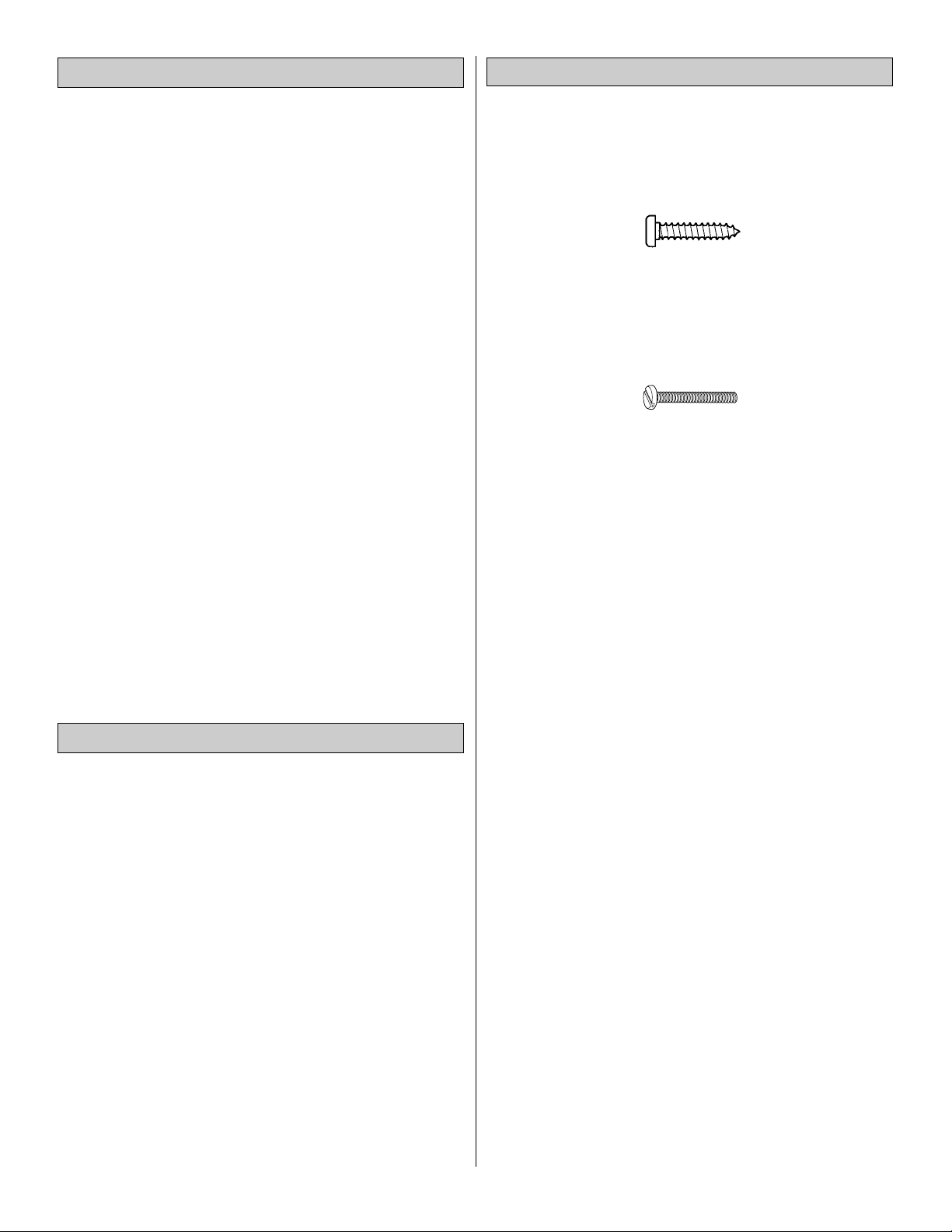
There are two types of screws used in this kit:
Sheet metal screws are designated by a number and a length.
For example #6 x 3/4”
This is a number six screw that is 3/4”long.
Machine screws are designated by a number, threads per
inch, and a length.
For example 4-40 x 3/4”
This is a number four screw that is 3/4” long with forty
threads per inch
.
When you see the term
test fit
in the instructions, it means
that you should first position the part on the assembly
without using any glue, then slightly modify or
custom fit
the part as necessary for the best fit.
Whenever the term
glue
is written you should rely upon
your experience to decide what type of glue to use.When a
specific type of adhesive works best for that step, the
instructions will make a recommendation.
Whenever just
epoxy
is specified you may use
either
30minute (or 45-minute) epoxy or6-minute epoxy. When 30minute epoxy is specified it is highly recommended that
you use only 30-minute (or 45-minute) epoxy, because you
will need the working time and/or the additional strength.
Photos and sketches are placed before the step they
refer to. Frequently you can study photos in following steps
to get another view of the same parts.
The Easy Sport 40 ARF is factory-covered with Top Flite
MonoKote film. Should repairs ever be required, MonoKote
can be patched with additional MonoKote purchased
separately. MonoKote is packaged in six-foot rolls, but some
hobby shops also sell it by the foot. If only a small piece of
MonoKote is needed for a minor patch, perhaps a fellow
modeler would give you some. MonoKote is applied with a
model airplane covering iron, but in an emergency a regular
iron could be used. A roll of MonoKote includes full
instructions for application.Following are the colors used on
this model and order numbers for six foot rolls.
White . . . . . . . .TOPQ0204
Red . . . . . . . . .TOPQ0201
Gray . . . . . . . . .TOPQ0220
Royal Blue . . . .TOPQ0221
Important Building Notes
Optional Supplies and Tools
Adhesives and Building Supplies
4
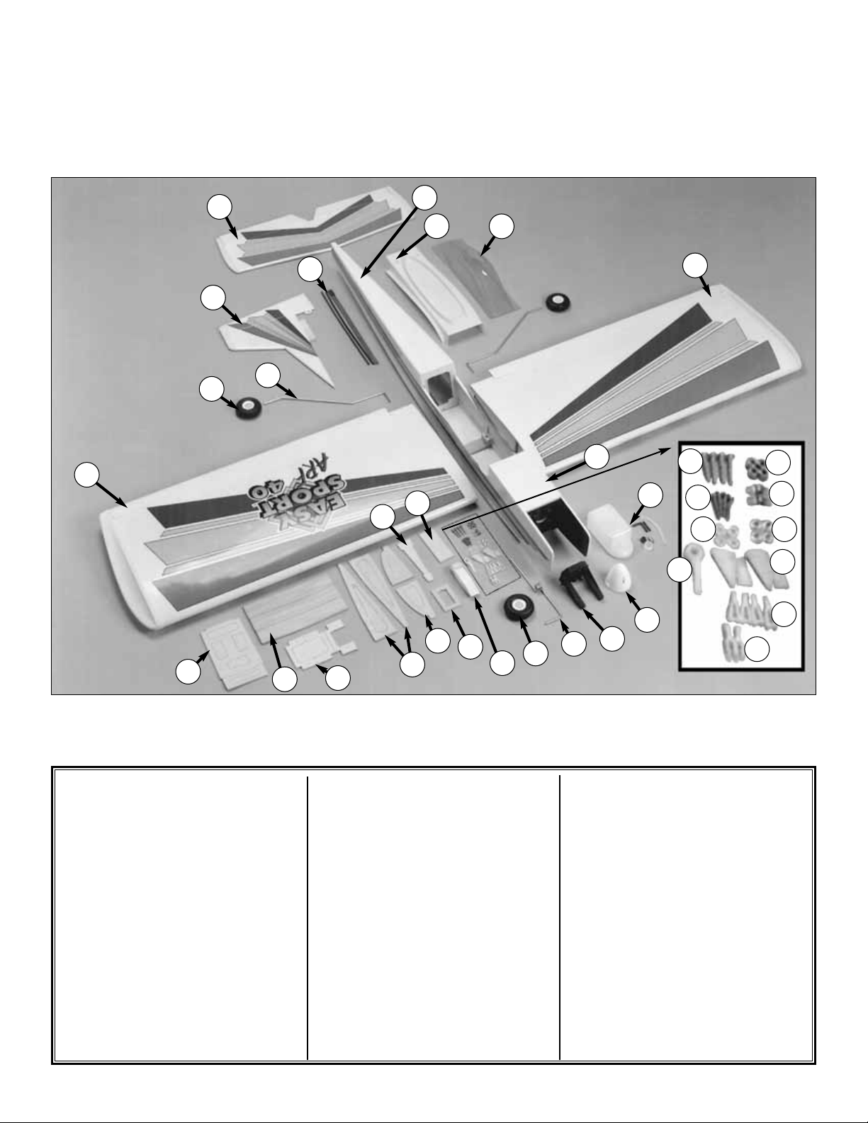
5
1 Stabilizer/Elevator Assembly
2 Rudder/Fin Assembly
3 Wheels
4 Main Landing Gear Wire
5 Pushrods
6 Right Wing Panel
7 Servo Tray
8 Wing Joiner
9 Plywd Wing Hold-Down Plates
10 Aft Root Ribs
11 Forward Root Ribs
12 Aileron Servo Tray
13 Stabilizer Mounting Base
14 Wing Bolt Plate
15 Wing Tape
16 6-32 x 1" Screws
17 Wheel Collars
18 6-32x3/4" Sheet Metal Screws
19 Nylon Landing Gear Straps
20 #6 Flat Washers
21 Silicone Clevis Retainers
22 Nylon Steering Arm
23 Nylon Control Horns
24 Nylon Clevis
25 Swivel Clevis
26 Nose Gear Wire
27 Engine Mount R & L
28 Spinner
29 Fuel T ank Assembly
30 Left Wing Panel
31 Canopy
32 Wing Fairing
33 Fuselage
34 Hatch
29
34
16
17
18
20
22
19
21
23
24
25
30
31
32
33
2
3
4
5
6
7
8
9
10
11
12
13
14
15
3
26
27
28
1
PARTS LIST
Before starting to build, use the Kit Contents list to take an inventory of this kit to make sure it is complete, and inspect
the parts to make sure they are of acceptable quality. If any par ts are missing or are not of acceptable quality, or if you
need assistance with assembly, contact Product Support. When repor ting defective or missing parts, use the part names
exactly as they are written in the Kit Contents list on this page.
Great Planes Product Support:Telephone: (217) 398-8970 Fax: (217) 398-7721 E-mail:
airsupport@greatplanes.com
6
Note: As epoxy is used for most of this kit’s assembly, it’s a
good idea to keep rubbing alcohol and paper towels handy
for cleanup. Before the epoxy has had time to cure, moisten
a paper towel with alcohol and clean off any e xcess epoxy.
❏ 1. Lightly sand the edges of the three plywood wing
joiners to remove any rough edges. Use 6-minute epoxy to
glue the three pieces together. Be sure that the slight
dihedral angle is on the same edge of all three pieces.
Clamp the wing joiners together or weigh them down on a
flat surface while the epoxy cures.
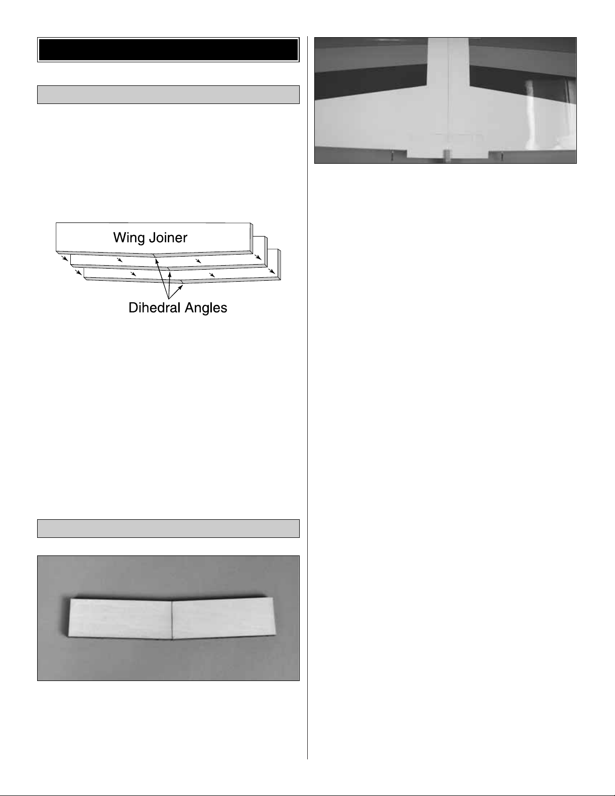
❏ 1. Draw a centerline on the wing joiner as shown in the
photo. Test fit the wing joiner into each wing panel. You
must be certain that the joiner fits all the way into the wing
panels. The joiner should fit snugly into each wing panel.
Sand the joiner if it does not fit snugly or does not fit
completely into the wing panels.
❏ 2. Sand the inside of both wing roots for a nice flush fit.
Test fit the panels together with the wing joiner in place.
The angled edge of the joiner points towards the bottom of
the wing. Check the alignment of the leading and trailing
edges. They should line up nicely with the roots fitting
together without any gaps. Sand the root ribs if any
imperfections are keeping the wing halves from fitting
together properly.
Carefully read and practice the following step
completely before mixing any epoxy. The entire step
must be completed before the epoxy begins to set.
❏ 3. When you are satisfied with the fit, pull the panels apart
and mix up a large batch (about 3/4 oz.) of 30-minute
epoxy. Using an epoxy mixing stick, liberally spread epoxy
inside both of the joiner slots and on one half of the joiner
itself.Next, quickly install the glued end of the joiner into one
of the slots. Spread more epoxy onto the root ribs and the
protruding end of the wing joiner. Slide the two wing panels
together. The epoxy should squeeze out around the edges.
This is a good sign that there is enough epoxy to securely
join the two wing halves. Double check the alignment and
wipe off any excess glue with a paper towel and rubbing
alcohol. Hold the two wing halves together using masking
tape. Continually check the alignment of the wing halves
while the epoxy cures.
❏ 4. Once the glue has cured, check the joint for any small
gaps and fill them with epoxy. Wipe off any excess epoxy
using a paper towel and rubbing alcohol. The paper towel
can also be used to remove any fingerprints or epoxy
residue that may have been left behind.
Join the Wing Panels
Assemble the Wing Joiners
WING ASSEMBLY

7
❏ 1. Lay the 1/8” [3.2mm] ply aileron servo tray on the
bottom of the wing. Center the tray over its mounting area
and draw a line on the covering around it using a felt-tip
marking pen.
❏ 2. Remove the covering inside the lines with a hobby
knife, being careful not to cut into the wood.Glue the ser vo
tray in place with 6-minute epoxy or medium CA.
❏ 3. After the glue has cured, trim the wood inside the
servo tray. Trial fit the servo in the tray, trimming the tray
and wing as needed.
❏ 1. Position the 1/8” [3.2mm] ply wing bolt plate 1/4”
forward of the trailing edge of the top of the wing. Use the
centerline on the wing bolt plate to center it on the centerline
of the wing.Draw a line around the plate on the covering using
a felt-tip pen. Remove the covering inside the lines with a
hobby knife , being careful not to cut into the wood.
❏ 2. Glue the wing bolt plate in position with 6-minute
epoxy or medium CA.
❏ 3. Turn the wing over and remove the covering from the
holes for the wing bolts. Using a 1/4” [6.4mm] drill bit, drill
holes through the wing bolt plate for the wing bolts.
Note:The following steps depict the installation of a 2-stroke
engine. The steps are similar if you are using a 4-stroke
engine, although some changes to the throttle pushrod
routings will need to be made.
❏ 1. Remove the center spreader from the engine mount
halves.Trim any excess flashing with a hobby knife or file.
❏ 2. This is a good time to fuelproof the engine
compartment. Lightly brush a mixture of 30-minute epoxy
thinned with isopropyl alcohol into the engine
compartment. Be careful not to get any of the epoxy into
the blind nuts that are located in the firewall.
Install the Engine
INSTALL FUSELAGE COMPONENTS
Install the Wing Bolt Plate
Install the Aileron Servo Tray
❏ 3. Fit the two halves of the engine mount together. Use
four #6 flat washers and four 6-32 x 1" [25.4mm] phillips
head screws to attach the engine mount to the firewall.
Blind nuts have already been installed in the firewall for this
purpose. Don’t tighten the screws completely yet, as the
mount will need to be adjusted to fit the engine.
❏ 4. Test fit the engine to the mount. Adjust the width of
the mounting rails to accommodate the engine without
being too tight or too loose. Tighten the mount screws so
that you can mark the engine screw holes without allowing
the rails to move. When you tighten the screws, slide the
mount as close to the right side of the fuselage as you can.
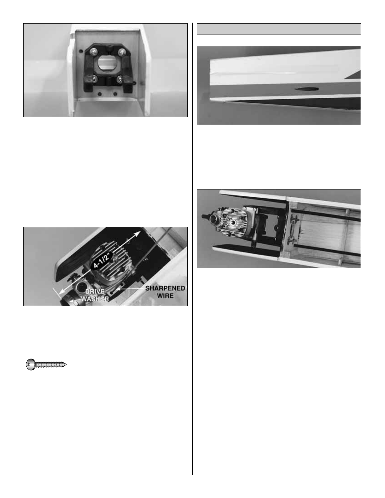
❏ 5. Position the engine so that the drive washer is
4-1/2" [114mm] from the firewall. Using one of the 17-1/2"
[444mm] push rods, sharpen the non-threaded end using a
file or sandpaper. Use this shar pened wire to scribe the four
mounting holes onto the rails. Use a 7/64" [2.8mm] drill bit to
drill pilot holes through the rails for the #6 sheet metal screws.
❏ 6. Attach the engine to the rails using four #6 x 3/4"
[19mm] sheet metal screws.
❏ 1. Locate the pushrod exit slot under the covering on the
tail section of the fuselage by lightly pressing with your
fingers. The slot should be located 4" [102mm] from the
rear the fuselage and 3/4" [19mm] from the bottom of the
fuselage. Trim the covering to provide access to the
pushrod exit.
❏ 2. Trim one of the pushrod tubes to 12" [305mm]. After
roughening the tube with 220-grit sand paper, install the
tube into the upper right hole in the firewall. This will be
used for the throttle pushrod. Leave about 1/4" [6.4mm] of
the tube exposed in front of the firewall. Glue the pushrod
tube to both sides of the firewall using medium CA.
Note: Depending on the engine you use, the location of the
pushrod holes may vary.
❏ 3. Trim the remaining pushrod tube to 13-1/2" for use as
the nose wheel pushrod tube. After roughening the tube
with 220-grit sand paper, install the tube into the lower left
hole in the firewall.This tube should be installed flush with
the front of the firewall. Glue the pushrod tube in place to
the former at the LE of the wing.
Install the Pushrod Tubes
#6 x 3/4" [19mm] Sheet Metal Screw (4)
8
 Loading...