

Page 1
WARRANTY
Great Planes Model Manufacturing Co. guarantees this kit to be free from defects in both material and
workmanship at the date of purchase. This warranty does not cover any component parts damaged by use or
modification. In no case shall Great Planes' liability exceed the original cost of the purchased kit. Further, Great
Planes reserves the right to change or modify this warranty without notice.
In that Great Planes has no control over the final assembly or material used for final assembly, no liability shall be
assumed nor accepted for any damage resulting from the use by the user of the final user-assembled product. By the
act of using the user-assembled product, the user accepts all resulting liability.
If the buyers are not prepared to accept the liability associated with the use of this product, they are
advised to return this kit immediately in new and unused condition to the place of purchase.
READ THROUGH THIS INSTRUCTION MANUAL
FIRST. IT CONTAINS IMPORTANT INSTRUCTIONS
AND WARNINGS CONCERNING THE ASSEMBLY
AND USE OF THIS MODEL.
ES03 V1.0 Entire Contents © Copyright 1996
P.O. Box 788 Urbana, IL 61801 (217) 398-8970
INSTRUCTION MANUAL
TM
ADE IN
SA
Page 2
INTRODUCTION ...............................................................2
PRECAUTIONS.................................................................3
DECISIONS YOU MUST MAKE........................................3
Engine Selection............................................................3
PREPARATIONS...............................................................3
Required Accessories ...................................................3
Building Supplies and Tools...........................................3
Optional Supplies and Tools .........................................4
Common Abbreviations..................................................4
Get Ready to Build.........................................................4
PARTS LIST......................................................................5
WING ASSEMBL Y.............................................................6
Assemble the Wing Joiners ...........................................6
Prepare the Wing Roots.................................................6
Join the Wing Panels.....................................................6
Install the Aileron Servo Tray.........................................7
Install the Wing Bolt Plate..............................................7
INSTALL FUSELAGE COMPONENTS.............................7
Install the Engine Mount ................................................7
Install the Servo Tray .....................................................8
Install the Pushrod Tubes ..............................................8
Assemble the Fuel Tank.................................................9
Completing the Engine & Fuel Tank Installation...........10
MOUNT THE WING TO THE FUSELAGE......................10
Installing the Wing Hold-Down Plate............................10
INSTALL THE TAIL COMPONENTS ..............................12
Join the Elevator Halves..............................................12
Align & Install the Stabilizer..........................................12
Install the Vertical Fin...................................................14
Install the Elevator Halves ...........................................14
INSTALL THE LANDING GEAR.....................................15
Mount the Main Landing Gear .....................................15
Mount the Nose Gear...................................................15
RADIO INSTALLATION ..................................................16
Install the Radio Components......................................16
Install the Pushrods & Control Horns...........................17
FINAL ASSEMBLY..........................................................19
Balance the Propeller...................................................19
Install the Wheels.........................................................19
Install the Canopy........................................................19
Control Surface Throws...............................................20
Balance Your Model.....................................................20
PREFLIGHT.....................................................................21
Charge the Batteries....................................................21
Find a Safe Place to fly................................................21
Ground Check the Model.............................................21
Range Check the Radio...............................................21
Engine Safety Precautions...........................................21
FLYING ............................................................................22
Takeoff..........................................................................22
Flight............................................................................22
Landing........................................................................22
AMA Safety Code...........................................................23
FLIGHT LOG ...................................................Back Cover
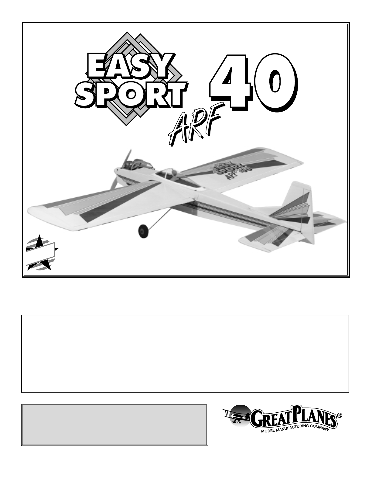
Your Easy Sport 40 is not a toy, but rather a sophisticated,
working model that functions very much like an actual
airplane. Because of its realistic performance, the Easy Sport,
if not assembled and operated correctly, could possibly cause
injury to yourself or spectators and damage property.
If this is your first sport model we recommend that you
get help from an experienced, knowledgeable modeler
with your first flights. You'll learn faster and avoid risking
your model before you're truly ready to solo. Your local
hobby shop has information about flying clubs in your area
whose membership includes qualified instructors.
You may also contact the national Academy of Model
Aeronautics (AMA), which has more than 2,300 chartered
clubs across the country.
Academy of Model Aeronautics
5151 East Memorial Drive
Muncie, IN 47302-9252
Tele. (800) 435-9262
Fax (317) 741-0057
Congratulations and thank you for purchasing the Great
Planes Easy Sport 40 ARF! This model has many features
that are usually found only in kit-type aircraft. These
features include: rod-in-tube pushrods, an adjustable glassfilled nylon engine mount, multiple color covering and high
quality Great Planes hardware. The construction technique
that is used for this aircraft results in a model that is lighter
and stronger than conventional, built-up balsa airplanes.
The Easy Sport 40 ARF will provide an excellent second
aircraft to help build confidence and assist in perfecting
your aerobatic skills.
The Great Planes Easy Sport 40 ARF is similar to the
original Easy Sport 40 kit. The Almost-Ready-to-Fly version
is stable enough to be a great second airplane, yet has
aerobatic capabilities which allows rapid advancement of
your aerobatic skills. This Easy Sport has the same good
looks and excellent stability at low speeds that can be
found on the kit version and reflects the design expertise
and high quality standards of Great Planes kits.
INTRODUCTION
PROTECT YOUR MODEL,YOURSELF
& OTHERS...FOLLOW THIS
IMPORTANT SAFETY PRECAUTION
TABLE OF CONTENTS
2
Page 3
Please inspect all parts carefully before starting to build!
If any parts are missing, broken or defective, or if you
have any questions about building or flying this
airplane, please call us at (217) 398-8970. If you are
calling for replacement parts, please reference the part
numbers and the kit identification number (stamped on
the end of the carton) and have them ready when calling.
1. Build the model according to the instructions. Do not
alter or modify the model, as doing so may result in an
unsafe or unflyable model. In a few cases the instructions
may differ slightly from the photos. In those instances the
written instructions should be considered correct.
2. Take time to build straight, true and strong.
3. Use a radio control system that is in first-class condition
and correctly-sized engine and components throughout
your building process.
4. You must properly install all components so that the
model operates properly on the ground and in the air.
5. You must check the operation of the model before every
flight to ensure that all equipment is operating, and that the
model has remained structurally sound. Be sure to check
nylon clevises or other connectors often and replace them if
they show signs of wear or fatigue.
6. If you are not already an experienced R/C pilot, you
should fly the model only with the help of a competent, well
experienced R/C pilot.
Remember: Take your time and follow directions to end
up with a well-built model that is straight and true.
Items in parentheses (OSMG2691) are suggested part
numbers recognized by distributors and hobby shops and
are listed for your ordering convenience. GPM is the Great
Planes brand, TOP is the Top Flite®brand, and HCA is the
Hobbico®brand.
❏ 4 Channel Radio with 4 Servos
❏ Engine - See Engine Selection above
❏ Propellers (see engine instructions for sizes)
❏ 18" Silicone fuel tubing (Great Planes #GPMQ4131)
❏ 1/4" Latex foam rubber for receiver & battery
(Hobbico #HCAQ1000)
Note: Larger wheels than those included may be required
for operation on rough grass fields.
These are the building tools, glue, etc. that we recommend
and mention in the manual. We recommended Great
Planes Pro™CA and Epoxy
❏ 1 oz. CA thin (Great Planes #GPMR6002)
❏ 1 oz. CA+ Medium (Great Planes #GPMR6008)
❏ 6-Minute Epoxy (Great Planes #GPMR6045)
❏ 30-Minute Epoxy (Great Planes #GPMR6047)
❏ Hand or electric drill
❏ Hobby saw (razor saw)
❏ Hobby knife, #11 Blades
❏ Common pliers
❏ Screwdrivers (phillips and flat blade)
❏ T-Pins
❏ String
❏ Straightedge with scale
❏ Masking tape (required for construction)
❏ Sandpaper (medium grit)
❏ T-Bar sander (or similar)
❏ Isopropyl rubbing alcohol (70%)
❏ Round file
❏ Felt-tip pen
❏ Mixing sticks
❏ Drill Bits: 1/16", 3/32", 5/64", 5/32", 7/64"
Building Supplies and Tools
Required Accessories
PREPARATIONS
Engine Selection
The recommended engine size range is as follows:
.40 to .51 cu. in. 2-stroke
.52 to .70 cu. in. 4-stroke
The Easy Sport 40 will fly well with any of the recommended
engine sizes. For “Hot Dogging” and speedy performance,
we suggest either an O.S.®.46 FX or a SuperTigre™GS-45,
both 2-stroke engines. An O.S. FS-70 Surpass is a good
choice for those who prefer 4-stroke engines.
DECISIONS YOU MUST MAKE
NOTE: We, as the kit manufacturer, can provide you
with a top quality kit and great instructions, but ultimately
the quality of your finished model depends on how you
build it; therefore, we cannot in any way guarantee the
performance of your completed model, and no
representations are expressed or implied as to the
performance or safety of your completed model.
PRECAUTIONS
3
Page 4
❏ Dremel
®
MultiPro™or similar
❏ 1 oz. Thick CA- (GPMR6014)
❏ 6-Minute Pro Epoxy (GPMR6045)
❏ CA Applicator Tips (HCAR3780)
❏ Epoxy Brushes (GPMR8060)
❏ CA Debonder (GPMR6039)
❏ Trim Seal Tool (TOPR2200)
❏ Heat Gun (TOPR2000)
❏ Straightedge (Fourmost Non Slip, FORR2149)
❏Kyosho Curved Scissors for trimming canopy (KYOR1010)
Elev = Elevator Fuse = Fuselage
LE = Leading Edge (front) LG = Landing Gear
Lt = Left Ply = Plywood
Rt = Right Stab = Stabilizer
TE = Trailing Edge (rear) " = Inches
1. Remove all parts from the box. As you do, identify each
part by comparing it with the parts list on page 5. Using a
felt-tip or ballpoint pen, lightly write the part name on each
piece to avoid confusion later. Use your bar sander or
sanding block to lightly sand the edges to remove any
irregularities or slivers.
2. As you identify and mark the parts, separate them into
groups, such as fuse (fuselage), wing, fin, stab (stabilizer)
and hardware.
Get Ready to Build
Common Abbreviations
Optional Supplies and Tools
4
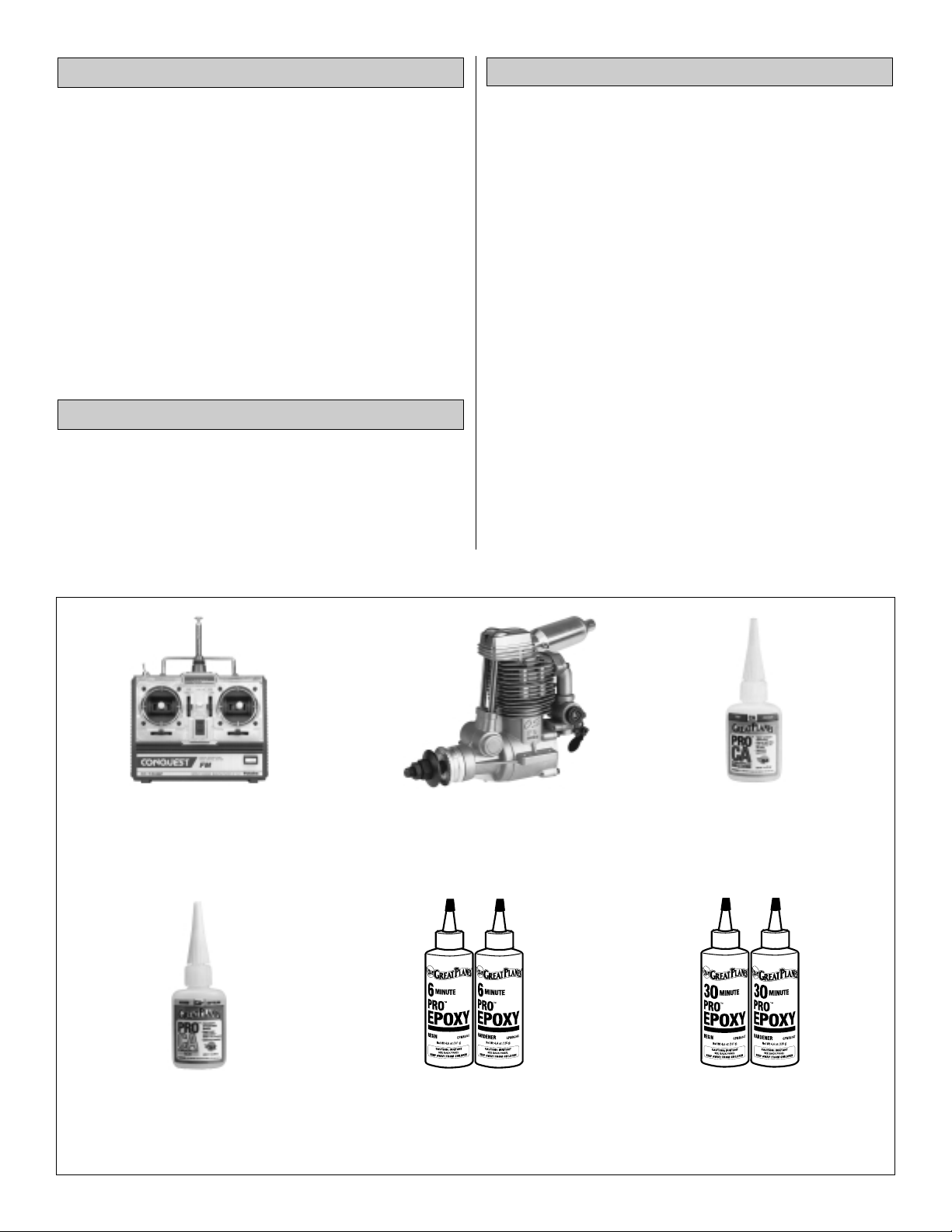
Futaba®4NBF Conquest 4-channel Radio
Flexibility and convenience make the Futaba
Conquest FM radio systems a good choice
for experienced fliers. FUTJ39**
Great Planes Pro™Thin, Instant Set CA
Instant-setting Pro CA is ideal for fast
assembly, with a curing time of 1-3 seconds.
All Pro CAs are dated for freshness.
GPMR6002
O.S.®.70 Surpass 4-stroke Engine
Lower noise, higher torque, increased fuel
economy and longer engine life make the
O.S. .70 Surpass engine an excellent choice
for your model. OSMG0870
Great Planes Pro Medium CA
Thick CA+ is an excellent gap filler that cures
in 10-15 seconds. All Pro CAs “wick” better
into balsa wood for the strongest possible
bond. GPMR6008
Great Planes Pro 6-minute Epoxy
Pure, powerful Pro 6-minute Epoxy cures
very quickly while also providing incredible
strength. Two-bottle set includes 4.5 oz.
bottles of epoxy and hardener. GPMR6045
Great Planes Pro 30-minute Epoxy
Pro 30-minute Epoxy provides modelers with
longer curing time to reposition parts and
provides greater strength for high-stress
areas. GPMR6047
Page 5
5
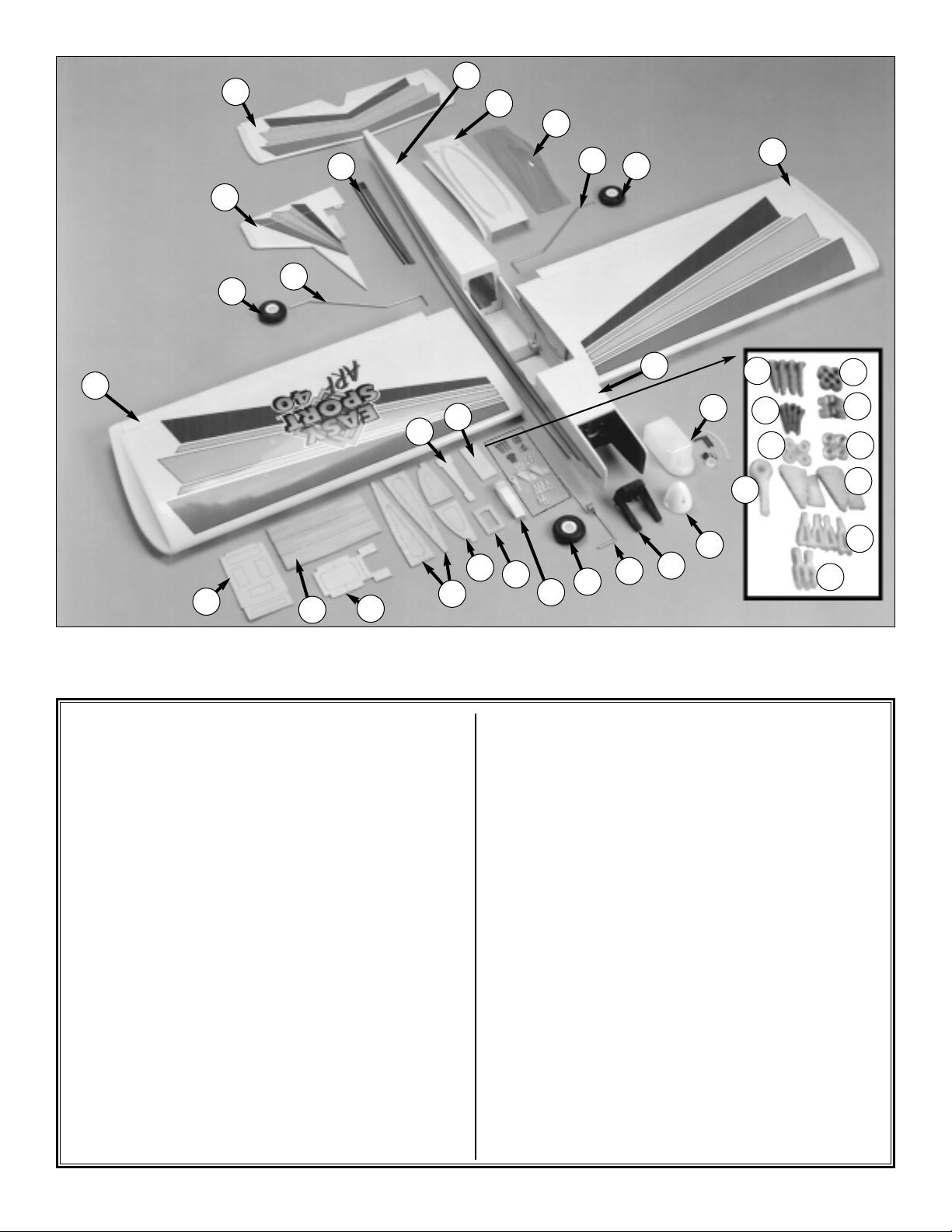
1 S tabilizer/Elevator Assembly
2 Rudder/Fin Assembly
3 Wheels
4 Main Landing Gear Wire
5 Pushrods
6 Right Wing Panel
7 Servo Tray
8 Wing Joiner
9 Plywood Wing Hold-Down Plates
10 Aft Root Ribs
11 Forward Root Ribs
12 Aileron Servo Tray
13 Stabilizer Mounting Base
14 Wing Bolt Plate
15 Wing Tape
16 6-32 x 1" Screws
17 Wheel Collars
18 6-32 x 3/4" Sheet Metal Screws
19 Nylon Landing Gear Straps
20 #6 Flat Washers
21 Silicone Clevis Retainers
22 Nylon Steering Arm
23 Nylon Control Horns
24 Nylon Clevis
25 Swivel Clevis
26 Nose Gear Wire
27 Engine Mount R & L
28 Spinner
29 Fuel Tank Assembly
30 Left Wing Panel
31 Canopy
32 Wing Fairing
33 Fuselage
34 Hatch
29
34
16
17
18
20
22
19
21
23
24
25
30
3
4
31
32
33
2
3
4
5
6
7
8
9
10
11
12
13
14
15
3
26
27
28
1
PARTS LIST
Page 6
6
Note: As epoxy is used for most of this kit’s assembly, it’s a
good idea to keep rubbing alcohol and paper towels handy
for cleanup. Before the epoxy has had time to cure, moisten
a paper towel with alcohol and clean off any excess epoxy.
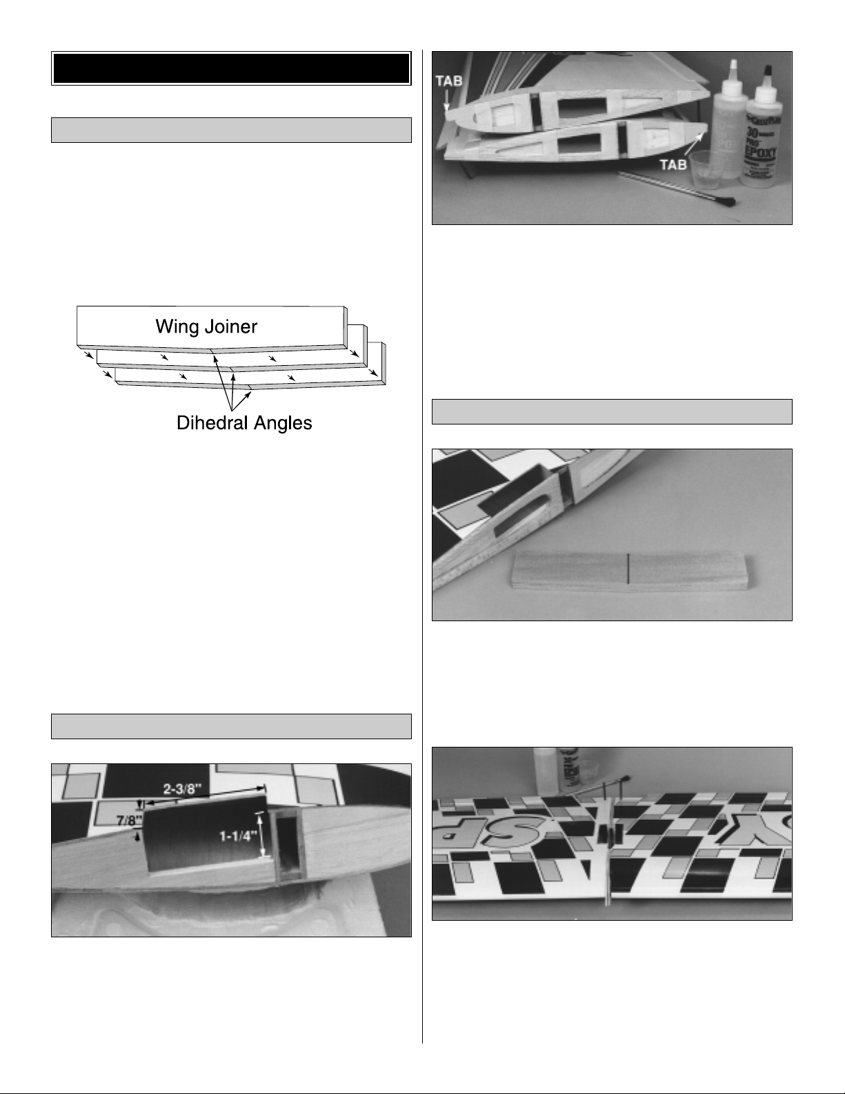
❏ 1. Lightly sand the edges of the three plywood wing
joiners to remove any rough edges. Use 30-minute epoxy
to glue the three pieces together. Be sure that the slight
dihedral angle is on the same edge of all three pieces.
Clamp the wing joiners together or weigh them down on a
flat surface while the epoxy cures.
❏ 2. Measure and mark the location of the aileron servo
tray opening. Using a sharp hobby knife, carefully cut the
opening for the aileron servo tray in both wing panels on
the bottom of each wing panel.
Note: The opening begins directly behind the wing spar.
❏ 3. Sand the inside of both wing roots for a nice flush fit.
Use 30-minute epoxy to glue the die-cut ply forward and
aft root ribs to both wing roots. Be sure that they are
aligned with the top and bottom of the wing. When
installing the forward root rib, it should be noted that the
tab is placed toward the top of the wing. Use strips of
masking tape to hold the parts in position until the epoxy
has cured.
❏ 1. Draw a centerline on the wing joiner as shown in the
photo. Test fit the wing joiner into each wing panel. You
must be certain that the joiner fits all the way into the wing
panels. The joiner should fit snugly into each wing panel.
Sand the joiner if it does not fit snugly or does not fit
completely into the wing panels.
❏ 2. Test fit the panels together with the wing joiner in
place. The angled edge of the joiner points towards the
bottom of the wing. Check the alignment of the leading
and trailing edges. They should line up nicely with the roots
fitting together without any gaps. Sand the root ribs if any
imperfections are keeping the wing halves from fitting
together properly.
Join the Wing Panels
Prepare the Wing Roots
Assemble the Wing Joiners
WING ASSEMBL Y
Page 7
7
Carefully read and practice the following step
completely before mixing any epoxy. The entire step
must be completed before the epoxy begins to set.
❏3. When you are satisfied with the fit, pull the panels apart
and mix up a large batch (about 1.5 oz.) of 30-minute
epoxy. Using an epoxy mixing stick, liberally spread epoxy
inside both of the joiner slots and on one half of the joiner
itself. Next, quickly install the glued end of the joiner into one
of the slots. Spread more epoxy onto the root ribs and the
protruding end of the wing joiner. Slide the two wing panels
together. The epoxy should squeeze out around the edges.
This is a good sign that there is enough epoxy to securely
join the two wing halves. Double check the alignment and
wipe off any excess glue with a paper towel and rubbing
alcohol. Hold the two wing halves together using masking
tape. Continually check the alignment of the wing halves
while the epoxy cures.
❏4. Once the glue has cured, check the joint for any small
gaps and fill them with epoxy. Wipe off any excess epoxy
using a paper towel and rubbing alcohol. The paper towel
can also be used to remove any fingerprints or epoxy
residue that may have been left behind.
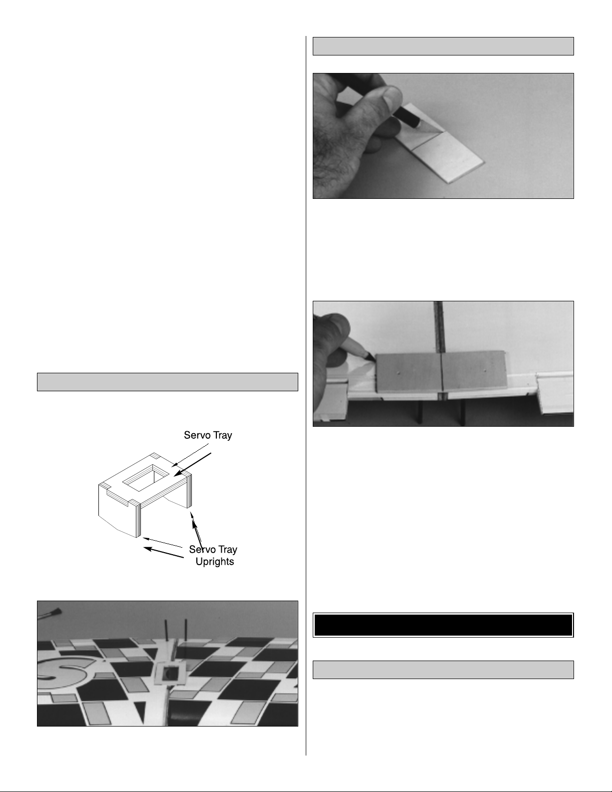
❏ 1. Glue the aileron servo tray and uprights into the wing
using 6-minute epoxy.
❏ 1. Lay the wing bolt plate on a table with the punch
marks facing upwards. Draw a centerline across the wing
bolt plate. Using a hobby knife, gently score the wing bolt
plate along this centerline. This score line is to allow the
wing bolt plate to be easily bent to the contour of the wing
and should not be cut completely through the plate.
❏ 2. Position the wing bolt plate on the trailing edge of
the top of the wing. Use the centerline on the wing bolt
plate to center it between the aft root ribs. Draw a line
around the plate on the covering using a felt-tip pen.
Carefully remove the covering with a hobby knife. Be
careful not to cut into the wood.
❏ 3. Using 6-minute epoxy, glue the wing bolt plate in
place with the punch marks facing up. Clamp it in position
while the epoxy cures.
Note: The following steps depict the installation of a 2-stroke
engine. The steps are similar if you are using a 4-stroke
engine, although some changes to the throttle pushrod
routings will need to be made.
Install the Engine Mount
INSTALL FUSELAGE COMPONENTS
Install the Wing Bolt Plate
Install the Aileron Servo Tray
Page 8
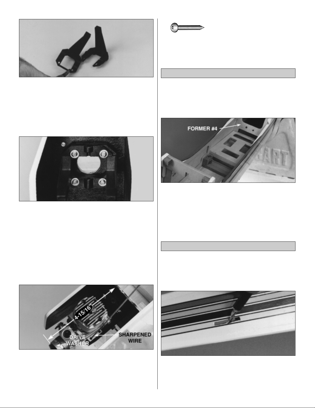
❏ 1. Remove the center spreader from the engine mount
halves. Trim any excess flashing with a hobby knife or file.
❏ 2. This is a good time to fuelproof the tank and engine
compartments. Lightly brush a mixture of 30-minute epoxy
thinned with isopropyl alcohol into both compartments. Be
careful not to get any of the epoxy into the blind nuts that
are located in the firewall.
❏ 3. Fit the two halves of the engine mount together. Use
four #6 flat washers and four 6-32 x 1" phillips head
screws to attach the engine mount to the firewall. Blind
nuts have already been installed in the firewall for this
purpose. Don’t tighten the screws completely yet, as the
mount will need to be adjusted to fit the engine.
❏ 4. Test fit the engine to the mount. Adjust the width of
the mounting rails to accommodate the engine without
being too tight or too loose. Tighten the mount screws so
that you can mark the engine screw holes without allowing
the rails to move.
❏ 5. Position the engine so that the drive washer is
4-15/16" from the firewall. Using one of the 17-1/2" push
rods, sharpen the non-threaded end using a file or
sandpaper. Use this sharpened wire to scribe the four
mounting holes onto the rails. Use a 7/64" drill bit to drill
pilot holes through the rails for the #6 sheet metal screws.
❏ 6. Attach the engine to the rails using four #6 x 3/4"
sheet metal screws.
❏1. Separate the two die-cut 1/8" (3.2mm) ply parts of the
servo tray assembly, then lightly sand off any rough spots
from the edges. Save the excess plywood for use in
later steps.
❏ 2. Test fit the servo tray assembly by first placing the
front brace behind the landing gear mounts. The servo tray
is then installed by “locking” it into the cut-out of former #4
and the front brace. When satisfied with the fit of these
components, glue them in place using medium CA. Be sure
to make a fillet along the joint between the servo tray and
the fuselage side.
❏ 1. Measure and cut a 21" length from each of the two
outer pushrod tubes supplied. The 21" pieces will be
used for the rudder and elevator. Save the pieces that were
cut off for the nose gear and throttle pushrods.
❏ 2. Locate the pushrod exit slot under the covering on
the tail section of the fuselage by lightly pressing with your
fingers. The slot should be located 3-3/4" from the rear the
fuselage and 7/8" from the bottom of the fuselage. Trim the
covering to provide access to the pushrod exit. Check the
Install the Pushrod Tubes
Install the Servo Tray
#6 x 5/8" Sheet Metal Screw (4)
8
Page 9

fit of the outer pushrod tubes to the pushrod exits. If the fit
is too tight, trim the opening slightly with a hobby knife to
allow the pushrod to fit without binding.
❏ 3. Roughen the outside of the outer pushrod tubes
using 220-grit sandpaper.
❏ 4. Insert the 36" threaded wire rods through the
pushrod tube openings into the fuselage from the rear and
guide them through former #4. Do not allow the pushrods to
cross each other inside the fuselage. If the pushrods are
crossed during the installation, the nose gear will operate in
the opposite direction of the rudder, making ground handling
of the aircraft rather difficult. Slide the outer pushrod tubes
into place from the inside using the threaded rods as guides.
Leave approximately 1" of the outer pushrod tube in front of
former #4. Apply thick CAto the points where the outer tubes
contact former #4 and at the exits.
❏ 5. Trim one of the remaining pushrod tubes to 12". After
roughening the tube with 220-grit sand paper, install the
tube into the upper right hole in the firewall. This will be
used for the throttle pushrod. Leave about 1/4" of the tube
exposed in front of the firewall. Glue the pushrod tube to
both sides of the firewall using medium CA.
❏ 6. Trim the other remaining outer pushrod to 13-1/2" for
use as the nose wheel pushrod tube. After roughening the
tube with 220-grit sand paper, install the tube into the lower
left hole in the firewall. This tube should be installed flush
with the front of the firewall. Glue the pushrod tube in place
from the back of the firewall using medium CA.
❏ 1. Push the straight nipple through the rubber
stopper until the ridge (1/4" from one end) contacts the
outside face of the stopper. Cut the pick-up tube to 2-7/8".
Push one end of the pick-up tube all the way onto the
clunk and the other end all the way onto the nipple.
❏ 2. Insert the pick-up tube assembly into the tank, then
thread the cap over the stopper, tightening it securely.
❏ 3. Wrap the 3-1/2" x 7-7/8" x 1/2" sheet of foam rubber
around the tank as shown in the photo. Secure it into
position with a couple of rubber bands. The reason for the
open area on the side of the tank is to allow clearance for
the throttle pushrod tube.
Assemble the Fuel Tank
9
Page 10

❏4. Insert two 12" pieces of fuel tubing through the hole in
the firewall. Place the fuel tank partially into the fuel tank
compartment and connect the lines to the tank. Work the
tank into position, centering it in the compartment. Cut the
fuel tube to the carburetor so the there are no sharp bends
or kinks in the fuel line.
❏ 1. Mark the position of the muffler cut-out onto the side
of the fuselage. Remove the engine at this point to prevent
any wood from entering the engine. Use a hobby knife
and/or razor saw to cut the fuse side to allow for at least
1/4" clearance around the muffler. Be sure to paint the
exposed wood with a fuelproof paint or epoxy.
❏2. Locate the position of the needle valve according to your
specific engine. Cut or drill the fuselage side to allow for ease
of needle adjustments. Leave a space around the needle so
that any vibrations will not affect the needle setting. Install the
muffler. Cut the tank pressure tube to the proper length, then
attach it to the muffler .
Note: A small piece of music wire or a cut down hex
wrench can be used to extend the needle if it does not
reach through the fuse side.
❏ 3. Fit the hatch in position. By measurement, determine
where to drill 1/16" holes in the four corners of the hatch to
pass through the center of the four underlying hardwood
blocks. Tape the hatch to the fuselage using masking tape
to prevent the hatch from moving while drilling the holes.
After drilling these holes, remove the hatch and enlarge
only the holes in the hatch to 3/32". Soak the inside of
the holes in the hatch with a drop or two of thin CA to
harden the balsa. Clean out the holes with a 3/32" drill bit
after the CA has cured. Attach the hatch with four #2 x 3/8"
sheet metal screws.
❏ 1. Lightly sand the edges of the three plywood wing
hold-down plates to remove any rough edges. Note that
one of the plates is slightly wider than the other two. This
plate is to be placed on the bottom. Use 30-minute epoxy to
glue the three pieces together. Clamp the wing hold-down
plates together or weigh them down on a flat surface while
the epoxy cures.
Installing the Wing Hold-Down Plate
MOUNT THE WING TO THE FUSE
Completing the Engine & Fuel
Tank Installation
10
Page 11

❏ 2. Test fit the assembled wing hold-down plate into the
fuselage, placing the larger plate downward and locking it
into the fuse sides. Sand or trim the plate to achieve
the best fit. Remove the plate and glue it in place using
30-minute epoxy.
❏ 3. Position the wing on the fuselage with the centerline
of the wing along the centerline of the fuselage. Hold a
string (with one end attached to a pin centered at the tail)
out to a wing tip. Put a piece of tape on the string to mark
the intersection of the string and the wing tip. Swing the
string over to the other wing tip and check to see if the
distances are the same. Make slight adjustments to the
angle of the wing until the distances from the tail to the
wing tips are equal.
❏ 4. Once the wing is aligned to the fuselage, use a 5/32"
drill bit to drill through the wing and into the wing hold-down
plate. When drilling, be sure that the drill bit remains
square to the wing bolt plate in all directions.
❏ 5. Enlarge the holes in the mounting blocks to 3/16". A
prop reamer or 3/16" drill bit may be used for this operation.
❏ 6. Slide one of the 4mm washers onto one of the 4mm
wing hold-down bolts. Slide the bolt through the wing
hold-down plate. Thread one of the blind nuts with the
“pronged” side up partially onto the wing hold-down bolts
from the underside of the wing hold-down plate. Put a
small drop of 30-minute epoxy on the prongs, then draw it
up into the wing hold-down plate by tightening the bolt.
Repeat this process for the other blind nut.
❏ 7. Slide the bolt/washer combination from the last step
through the wing from the top. Slide one of the rubber
O-rings onto the bolt from the bottom. The O-ring keeps the
bolt from falling out during transport.
11
Page 12

❏ 1. Without glue, position the elevator halves on the
stabilizer. Make sure that the elevators do not bind at the
tips. Measure and mark a centerline onto the elevator
joiner wire. Center the joiner between the two elevator
halves. Mark the position where the joiner will enter the
elevator halves.
❏ 2. Remove the elevator halves from the horizontal
stabilizer and drill straight into the leading edge of the
stabilizer using a 5/32" drill bit at the marks. Drill into the
elevators 1" to allow for complete insertion of the elevator
joiner. This step is done best using either a pin vise or
twisting the drill bit into the wood with your fingers.
❏ 3. Carefully cut grooves into the leading edges of the
elevator halves to allow the joiner to recess into the
leading edge.
❏ 4. Use a straightedge to align the elevator halves on a
flat surface. Using 6-minute epoxy, glue the joiner wire into
position. Make sure the joiner wire is fully seated in the
elevator halves before the epoxy cures. Use weights to
keep the elevator halves from moving.
❏ 1. Locate the horizontal stabilizer slot under the
covering on the tail section of the fuselage by lightly
pressing with your finger. The slot is located on both sides
of the fuselage. Carefully remove the covering, exposing
the slots with a hobby knife.
Note: Do not cut into the wood around the slot.
❏ 2. Locate the 1/8" plywood stabilizer mounting base
and test fit it into the bottom of the horizontal stabilizer slot.
Lightly sand the base if necessary to obtain a good fit.
Remove the base from the fuselage. Reinstall the plate
using a generous amount of 30-minute epoxy. Be sure that
there is enough epoxy to properly secure the stab base to
the fuselage. Remove any excess epoxy from the outside
of the fuselage with a paper towel and rubbing alcohol.
Align & Install the Stabilizer
Join the Elevator Halves
INSTALL THE TAIL COMPONENTS
12
Page 13

❏ 3. Carefully remove the tail post using a razor saw to
allow installation of the horizontal stabilizer.
❏ 4. Locate the slot for the vertical fin on the top of the
fuselage and remove the covering.
❏ 5. Measure and mark an accurate centerline on the top
of the horizontal stabilizer. Make sure to mark the
centerline on the trailing edge also.
❏ 6. Insert the stabilizer into the stabilizer slot so it is
centered in the fuselage (dimension A should be equal).
Place the wing onto the fuselage and secure it in place with
the wing hold-down bolts. View the plane from the rear and
at a distance of a few feet. The stabilizer should be parallel
to the wing (dimension B should be equal). If not, sand the
stabilizer mounting base slightly to achieve the proper
position of the stabilizer.
❏ 7. Attach a piece of string with a T-pin to the top center
of the firewall. The string should be long enough to reach to
the horizontal stabilizer. Align the stabilizer using the same
method that was used for aligning the wing.
❏ 8. With the stabilizer properly aligned, use a felt-tip pen
to trace a line around the tail of the airplane on the top and
bottom of the horizontal stabilizer.
❏9. Remove the stabilizer and draw two additional lines, top
and bottom, 1/16" inside the lines drawn in the previous step.
Using a new #11 knife blade, carefully cut through the
covering along the inside lines and remove the covering from
the center. Do not cut the wood under the covering! This
would seriously weaken the stabilizer and could easily
cause the stabilizer to break in flight. Be very careful
when you make this cut. If the covering is not removed from
the stabilizer , a proper bond will not be achieved.
13
Page 14

❏10. Mix 1/4 oz. of 30-minute epoxy. Using a mixing stick,
place glue inside the horizontal stabilizer mount. Place
more glue onto the bottom and top of the stabilizer where
the covering was removed. Insert the stabilizer from the
rear and adjust the alignment using the guide lines that
were drawn onto the stabilizer in step 8. Wipe off any
epoxy that squeezes out using a paper towel dampened
with rubbing alcohol. Recheck the alignment frequently
while the glue cures.
❏ 1. Remove the rudder from the vertical fin. Test fit the
vertical fin in the slot in the top of the fuselage. Sand the
edges of the slot if necessary to obtain a snug fit. Draw a
line around the forward portion of the vertical fin on the
fuselage. Remove the fin and cut 1/16" inside the line to
provide adequate gluing area for the vertical fin.
❏ 2. Mix 1/4 oz. of 30-minute epoxy. Using a mixing stick,
apply epoxy to the top of the horizontal stabilizer through
the slot. Also apply a small amount to the top of the
fuselage in the area the covering was removed. Check for
a 90Þ angle between the fin and horizontal stabilizer when
viewing from the rear. Use masking tape to hold the vertical
fin in this position. Check this alignment several times as
the epoxy cures.
❏1. Work the hinges into the slits in the trailing edge of the
horizontal stabilizer and press the elevators up to the edge
of the stabilizer. Flex the elevators all the way in one
direction, but do not allow the elevators to pull away from the
stabilizer. Apply 5 drops of thin CA onto each hinge. Do not
use accelerator while hinging, as the glue must wick into the
hinge to properly attach the hinges. Use a paper towel to
absorb any excess glue. Wait a few minutes for the glue to
set up, then repeat the process for the opposite side of the
elevators. After letting both sides dry, flex the elevators both
directions to free up the elevators for operation.
❏ 2. Carefully cut a slot in the tail post using a hobby
knife for the lower rudder hinge.
❏ 3. Temporarily install the rudder to determine where to
notch the rudder to allow clearance for the elevator joiner.
Press the rudder gently to leave an impression of the joiner
on the rudder. Remove the rudder and cut a notch that is
1/16" above and below the impression. The notch should
be cut 1/4" deep.
Install the Elevator Halves
Install the Vertical Fin
14
Page 15

❏ 4. Reinstall the rudder and make sure that the notch
allows proper clearance for the elevator joiner to operate
without binding when the rudder is fully deflected. Also, the
edges of the notch may need to be beveled to allow for full
movement of the rudder. Once you are satisfied that there
is no binding, glue the hinges using the same technique as
the elevator hinges.
REFER TO THIS PHOTO FOR THE FOLLOWING 3 STEPS
❏ 1. Locate the groove for the main landing gear under
the covering in the center of the fuselage by lightly
pressing with your finger. Using a hobby knife, carefully
remove the covering, exposing the groove.
Note: Do not cut into the wood around the groove.
❏ 2. Carve a slight bevel on the inside edge of both holes.
This is to allow for the radius at the bend in the landing gear.
❏ 3. To prevent fuel from damaging the exposed wood, a
thin coat of thin CA should be applied. This can be done by
applying the CA, then using a piece of waxed paper or
plastic, spread the glue until the wood has been completely
covered by the CA.
❏ 4. Measure in 1" from the outside edges of the fuselage
at the landing gear groove to locate the position of the
landing gear straps. Drill a 1/16" hole 3/32" from the rear
edge only at this time.
❏ 5. Install the main landing gear into position. Install the
landing gear straps using two of the #2 x 3/8" screws.
Note:Do not tighten the screws yet.
❏ 6. Using the holes in the front of the straps as a guide,
drill a 1/16" hole for the front screws.
❏ 7. Install the last two #2 x 3/8” screws. Remove all four
screws and harden the holes using two or three drops of thin
CA in each hole. After the CA has has time to cure, reinstall
the screws, making sure they are tightened completely .
❏ 1. Insert a 5/32" wheel collar (without a screw) into the
nylon steering arm. Be sure that the set screw holes on
Mount the Nose Gear
Mount the Main Landing Gear
INSTALL THE LANDING GEAR
15
Page 16

both parts are aligned. Slide the steering arm over the
straight end of the nose gear wire. Insert the wire through
the lower gear hole in the engine mount. Install a 5/32"
wheel collar onto the nose gear wire above the hole. Slide
the nose gear into the upper hole in the engine mount.
Adjust the height of the nose gear wire until the fuselage
sits level. Install a 6-32 set screw into the wheel collar and
tighten the set screw while the wheel collar is resting on
top of the lower portion of the engine mount hole.
❏ 2. Slide the steering arm into contact with the bottom of
the engine mount. Rotate the gear wire so that the axle is
parallel to the firewall. Insert the 6-32 x 1/4" screw into the
steering arm and thread it in a few turns. Position the
steering arm in front of the pushrod hole with the tip of the
arm approximately 5/8" away from the firewall. Tighten the
screw securely.
Note: After the gear has been installed and tested, remove
the nose gear strut. File or grind a flat spot on the gear wire
at the screw location. This is necessary to prevent the nose
gear steering arm from slipping.
1. Follow this sequence for mounting the radio components:
❏A. Install rubber grommets and brass eyelets in the servos
following the radio manufacturer’s recommendations.
❏B. Test fit the servos in the tray. Enlarge the openings if
needed to create a 1/32" gap around the servo.
❏C. Mark the mounting hole locations on the tray, then
drill 1/16" pilot holes through each mark.
❏D. Mount the servos with the screws provided with
your radio.
❏E. Wrap the receiver and battery with 1/4" foam (not
included). Use masking tape or rubber bands to hold
the foam in position.
❏ 1. Following the manufacturer’s recommendations,
install and connect three servos, the receiver, the switch
and the battery as shown in the photo. We added a Great
Planes Switch Mount & Charge Jack (#GPMM1000, not
included) for convenience and ease of use at the field. It is
installed in the side of the fuselage opposite the engine
exhaust. Center the elevator and rudder trims on the
transmitter. Turn the radio on and center the servo arms.
❏ 2.Assemble the swivel clevises by snapping the two
parts together, then thread a 17-1/2" wire pushrod
13 revolutions into each of them. Thread the swivels onto the
torque rods until they are 3/4" above the surface of the wing.
Cut off the excess torque rod that extends past the swivel.
❏ 3. Cut a notch in the aileron servo tray so the wire from
the servo can pass through. Install the aileron servo as
shown in step 4. Connect it to the receiver, turn on the
radio, then center the servo horn.
Install the Radio Components
RADIO INSTALLATION
16
Page 17

❏ 4. Center the ailerons, then mark the pushrods at the
point where they meet the holes on the servo arm. Make a
90 degree bend down in the wires at this mark.
❏ 5. Cut off the excess wire 3/8" above the bend. Enlarge
the servo horn holes with a 5/64" drill bit. Insert the bent
wire pushrods into the servo horn from the upper side, then
secure them with Nylon FasLink™Pushrod Keepers.
❏ 1. Slide a silicone retainer over the “hex” end of a
nylon clevis. Thread the clevis 13 revolutions onto the
threaded end of a 37" wire pushrod. Cut six 1/4"
bushings from the 6-1/2" plastic inner pushrod tube
provided in the kit. Slide the bushings on the wire pushrod,
spacing them about 3" apart. Check the pushrod to be
certain that the bushings won’t pop out of the ends and
cause the pushrods to stick. Put a drop of thin CA on the
pushrod wire at each bushing to hold them in place. Trim
the backing plate from a nylon control horn, then clip the
clevis to the top hole of the horn. Make a second assembly
exactly the same as the first. Clevis placement will be
adjusted on the horn for proper control throw later.
Note: Make sure the CA has fully cured before
proceeding to the next step.
❏ 2. Insert the pushrods into the tubes in the fuselage.
Hold the horn against the control surface (see sketch
above for correct alignment). Note: Be sure that the control
horn positions match those in the photo. The pushrod
should not be bent and should slide easily in the tube.
Mark the location for the horn screws on the control
surface. Drill the 3/32" horn screw holes through the control
surface. Mount the horn tightly in place with two 2-56
machine screws and the horn backing plate. Repeat for
the other control surface as shown.
❏❏3. Install a Screw-Lock Pushrod Connector with
the 4-40 x 1/8" cap screw on the throttle and rudder servo
horns. Snap the nylon retainer onto the pushrod
connector post beneath the servo horn. Use the photo for
the correct positioning of the connectors.
Install the Pushrods & Control Horns
17
RIGHT WRONG
Page 18

❏❏4. Center the elevator, then mark the pushrod where
it crosses the servo horn hole. Enlarge the servo horn hole
with a 5/64" drill bit. Make a 90 degree bend in the pushrod
on the mark. Cut off the excess wire 3/8" above the bend.
Insert the bent wire through the enlarged hole in the servo
horn. Secure it in place with a Nylon FasLink. (Doesn’t this
sound similar to the same procedure used for the aileron
pushrods?) Note the position of the FasLink in step 7.
❏5. Repeat steps 3 and 4 for the rudder pushrod.
❏ 6. Assemble the 17-1/2" throttle pushrod by installing a
nylon clevis and silicone retainer onto the threaded end.
Cut four 1/4" bushings and install them 2-1/2" apart. Slide
the throttle pushrod into its outer tube (from the firewall in),
then through the pushrod connector. Attach the clevis to
the control arm of the carburetor.
❏ 7. With the radio on, move the throttle trim lever and
control stick to the fully closed position, by pulling them
back (or downward) all the way. Manually close the throttle
on the carburetor completely. Tighten the set screw on the
pushrod connector. Check throttle operation with the radio
and make adjustments to the linkage as necessary for
smooth operation from fully closed to fully open. Use the
appropriate holes in the servo horn and throttle arm to
provide the correct amount of throttle movement and to
prevent the servo from binding at its end points.
❏ 8. Cut four 1/4" bushings and slide them onto the
remaining 17-1/2" pushrod 3" apart, starting 2-1/2" from
the non-threaded end. Bend the rod 90 degrees 1/2" from
the non-threaded end.
❏ 9. Drill a 5/64" hole through the center hole in the nose
gear steering arm. Insert the straight end of the steering
pushrod (from the firewall in) into the pushrod tube, into the
pushrod connector on the rudder servo. (Don’t cut the wire
or tighten the connector yet.) Work the wire into the
steering arm as shown in the photo.
❏ 10. Turn the radio on. Check that the rudder trim is
centered. Align the nose wheel axle with the firewall by
moving the pushrod. When the axle is parallel with the
firewall, tighten the set screw on the pushrod connector.
❏ 11. Using the leftovers that were saved from the servo
tray, make small stand-offs to secure the ends of the
throttle and nose wheel pushrods. Avoid getting any glue
inside of the pushrod tubes.
❏ 12. Drill a 1/16" hole through the bottom center of the
fuselage in front of the main landing gear block. Route the
receiver antenna through this hole. Put a small pin in the rear
of the fuselage. Use a rubber band tied around the antenna
wire and loop it around the pin to secure the antenna.
Note: Do not cut or shorten the antenna wire. Leave any
excess to hang free.
❏ 13. Once the model has been properly balanced, use
“popsicle sticks” or leftover wood glued between the fuse
sides to hold the receiver and battery securely in place.
18
Page 19

❏ 1. Carefully balance your propellers before flying. An
unbalanced prop is the single most significant cause of
vibration. Not only may engine mounting screws vibrate out,
possibly with disastrous effect, but vibration may also
damage your radio receiver and battery. Vibration may cause
your fuel to foam, which will, in turn, cause your engine to
run lean or quit. We use a Top Flite Precision Magnetic
Prop Balancer (TOPQ5700) in the workshop and keep a
Great Planes Fingertip Balancer (GPMQ5000) in our
flight box.
❏2. Push the spinner backplate onto the prop shaft all the
way. The center hole may be enlarged with a prop reamer or
drill if necessary. Align a prop next to the “short” pins, but not
between the “long & short” pins on the backplate. Finger
tighten the prop nut and washer. Rotate the prop shaft
counterclockwise until the engine reaches its compression
stroke. Hold the prop shaft (or rear prop washer) while
rotating the spinner backplate and propeller to the two
o’clock position. Tighten the prop nut securely. Attaching the
propeller in this position allows easier flip starting.
❏ 3. Attach the spinner to the backplate using the two
M3 x 15 screws.
❏ 1. Install the three wheels using the six 5/32" wheel
collars and set screws. Grind or file a flat spot at the point
of the set screw contact for each of the outer collars. This
provides a better area for the set screw to “bite” and helps
keep the wheels in place.
❏ 1. Mount the wing to the fuselage. Trim out the wing
fairing and position it on the fuselage. Mark the edges
around the wing fairing. Remove the fairing. Lightly sand the
wing fairing and the wing where they contact each other.
Clean the areas with rubbing alcohol and a paper towel to
remove any dust or oil. Mix 1/4 oz. of 30-minute epoxy and
glue the wing fairing in place. Use masking tape to hold it in
place until the glue cures. Any excess epoxy can be cleaned
up using a paper towel and rubbing alcohol.
❏ 2 Carefully trim the canopy along the “cut lines” with a
scissors or Lexan®scissors. Test fit the canopy on the wing
fairing as you proceed, making small adjustments as
required for a good fit. The area inside the canopy can be
detailed at this time by painting and adding a pilot figure to
Install the Canopy
Install the Wheels
Balancing the Propeller
FINAL ASSEMBLY
19
Page 20

suit your own personal tastes. Roughen the bottom 1/8" of
the canopy edge, as well as the area on the wing fairing that
the canopy contacts. Be careful not to scratch any areas that
may be visible when the canopy is installed. Glue the
canopy in position with 6-minute epoxy or RC-56 glue. Finish
the canopy by painting the frame lines using fuelproof paint
or striping tape.
Note: Always test your paint on a small sample of the
canopy to make sure that it doesn’t attack or deform the
the canopy material.
Note: This section is VERY IMPORTANT and must NOT
be omitted! A model that is not properly balanced will be
unstable and possibly unflyable.
❏1. Accurately mark the balance point on the bottom of the
wing on both sides of the fuselage. The balance point is
located 4-1/8" back from the leading edge. This is the
balance point at which your model should be balanced for
your first flights. Later, you may wish to experiment by shifting
up to 1/4" forward or aft to change the flight characteristics.
Moving the balance forward may improve the smoothness
and arrow-like tracking, but it may then require more speed
for takeoff and make it more difficult to slow down for landing.
Moving the balance point aft makes the model more agile
with a lighter and snappier “feel” and often improves knife
edge capabilities. In any case, please start at the location
we recommend and do not at any time balance your
model outside the recommended range.
❏ 2. With the wing attached to the fuselage, all parts of the
model installed (ready to fly) and an empty fuel tank, hold the
model at the marked balance point with the stabilizer level.
❏ 3. Lift the model. If the tail drops when you lift, the
model is “tail heavy” and you must add weight* to the nose.
If the nose drops, it is “nose heavy” and you must add
weight* to the tail to balance.
Note: Nose weight may be added by using a Heavy Spinner
nut (1/4"-28 GPMQ4640)(5/16"-24 GPMQ4641) or by gluing
weights to the firewall. Tail weight may be added by using
Great Planes (GPMQ4485) “stick-on” lead weights. Later, if
the balance proves to be O.K., you can open the bottom of
the fuse and glue these permanently in position.
*If possible, first attempt to balance the model by changing
the position of the receiver battery and receiver. If you are
unable to obtain good balance by doing so, then it will be
necessary to add weight to the nose or tail to achieve the
proper balance point.
Balance Your Model
Note: Throws are measures at the widest part of the
elevators, rudder and ailerons.
We recommend the following control surface throws:
High rates Low rates
ELEVATOR 1/2" UP 3/8" UP
1/2" DOWN 3/8" DOWN
RUDDER 1-1/4" RIGHT 1" RIGHT
1-1/4" LEFT 1" LEFT
AILERONS 7/16" UP 5/16" UP
7/16" DOWN 5/16" DOWN
Control Surface Throws
20
4-CHANNEL RADIO SETUP
(STANDARD MODE 2)
4-1/8"
ELEVATOR MOVES UP
4-CHANNEL
TRANSMITTER
RIGHT AILERON MOVES UP
LEFT AILERON MOVES DOWN
4-CHANNEL
TRANSMITTER
RUDDER MOVES RIGHT
NOSE WHEEL TURNS RIGHT
4-CHANNEL
TRANSMITTER
CARBURETOR WIDE OPEN
4-CHANNEL
TRANSMITTER
Page 21

Follow the battery charging procedures in your radio
instruction manual. You should always charge your transmitter
and receiver batteries the night before you go flying and at
other times as recommended by the radio manufacturer.
The best place to fly your R/C model is an AMA (Academy
of Model Aeronautics) chartered club field. Ask your hobby
shop dealer if there is such a club in your area and join.
Club fields are set up for R/C flying and that makes your
outing safer and more enjoyable. The AMA also can tell you
the name of a club in your area. We recommend that you
join AMA and a local club so you have a safer place to fly
and have insurance to cover you in case of a flying
accident. The AMA address is listed on page 2 of this
instruction manual.
If a club and its flying site are not available, you need to
find a large, grassy area at least 6 miles away from any
other R/C radio operation like R/C boats and R/C cars and
away from houses, buildings and streets. A schoolyard may
look inviting but it is too close to people, power lines and
possible radio interference.
Inspect your radio installation and confirm that all the control
surfaces respond correctly to transmitter inputs. The engine
operation must also be checked by confirming that the engine
idles reliably and transitions smoothly and rapidly to full power
and maintains full power indefinitely. The engine must
be “broken-in” on the ground by running it for at least
two tanks of fuel. Follow the engine manufacturer's
recommendations for break-in. Make sure all screws
remain tight, that the hinges are secure and that the prop is
on tight.
Whenever you go to the flying field, check the operational
range of the radio before the first flight of the day. First, make
sure no one else is on your frequency (channel). With your
transmitter antenna collapsed and the receiver and
transmitter on, you should be able to walk at least 100 feet
away from the model and still have control. While you work
the controls, have a helper stand by your model and tell you
what the control surfaces are doing. Repeat this test with
the engine running at various speeds with a helper holding
the model. If the control surfaces are not always responding
correctly , do not fly! Find and correct the problem first. Look
for loose servo connections or corrosion, loose bolts that
may cause vibration, a defective on/off switch, low battery
voltage or a defective cell, a damaged receiver antenna or a
receiver crystal that may have been damaged from a
previous crash.
NOTE: Failure to follow these safety precautions may
result in severe injury to yourself and others.
Keep all engine fuel in a safe place, away from high heat,
sparks or flames as fuel is very flammable. Do not smoke
near the engine or fuel; and remember that the engine
exhaust gives off a great deal of deadly carbon monoxide.
Do not run the engine in a closed room or garage.
Get help from an experienced pilot when learning to
operate engines.
Use safety glasses when starting or running engines.
Do not run the engine in an area of loose gravel or sand;
the propeller may throw such material in your face or eyes.
Keep your face and body as well as all spectators away
from the plane of rotation of the propeller as you start and
run the engine.
Keep these items away from the prop: loose clothing, shirt
sleeves, ties, scarfs, long hair or loose objects such as
pencils and screwdrivers that may fall out of shirt or jacket
pockets into the prop.
Use a “chicken stick” or electric starter; follow instructions
supplied with the starter or stick. Make certain the glow
plug clip or connector is secure so that it will not pop off or
otherwise get into the running propeller.
Make all engine adjustments from behind the propeller.
Engine Safety Precautions
Range Check Your Radio
Ground Check the Model
Find a Safe Place to Fly
Charge the Batteries
At this time check all connections including servo arm
screws, FasLinks, clevises and servo cords. Make sure
you have installed the nylon retainer on the Screw-Lock
Pushrod Connector on the throttle pushrod at the servo
arm and the silicone retainers on all the clevises.
PREFLIGHT
21
Page 22

The engine gets hot! Do not touch it during or after
operation. Make sure fuel lines are in good condition so
fuel will not leak onto a hot engine causing a fire.
To stop the engine, cut off the fuel supply by closing off the
fuel line or follow the engine manufacturer's
recommendations. Do not use hands, fingers or any other
body part to try to stop the engine. Do not throw anything
into the propeller of a running engine.
The Great Planes Easy Sport is a great flying sport airplane
that flies smoothly and predictably, yet is highly
maneuverable. It does not, however, have the self-recovery
characteristics of a primary R/C trainer; therefore, you must
either have mastered the basics of R/C flying or obtained
the assistance of a competent R/C pilot to help you with
your first flights.
If you have dual rates on your transmitter, set the switches
to “high rate” for takeoff, especially when taking off in a
cross wind. Although the Easy Sport has great low speed
characteristics, you should always build up as much speed
as your runway will permit before lifting off, as this will give
you a safety margin in case of a “flame-out.” When the
plane has sufficient flying speed, lift off by smoothly
applying a little up elevator and climb out gradually.
We recommend that you take it easy with your Easy Sport
for the first several flights and gradually “get acquainted”
with this fantastic airplane as your engine gets fully brokenin. Add and practice one maneuver at a time, learning how
she behaves in each one. For ultra-smooth flying and
normal maneuvers, we recommend using the “low rate”
settings as listed on page 20. If you notice any
“sluggishness” in the way your Easy Sport handles, it is
probably a result of not enough speed, in which case you
should install a propeller with increased pitch.
When it's time to land, fly a normal landing pattern and
approach. If you find that it lands a little fast, you might try
dialing in a few clicks of up elevator when you cut the
throttle on the downwind leg of the landing pattern. This will
automatically help to bleed off some of the speed. If your
Easy Sport is built straight and true, you'll find that you can
really flare it out for slow, nose-high, full-stall landings
without fear of tip stalling.
Have a ball, but always stay in control and fly in a safe
manner. GOOD LUCK AND GREAT FLYING!
Landing
Flight
CAUTION (THIS APPLIES TO ALL R/C AIRPLANES): If,
while flying, you notice any unusual sounds, such as a
low-pitched “buzz”, this may indicate control surface
“flutter”. Because flutter can quickly destroy components
of your airplane, any time you detect flutter you must
immediately cut the throttle and land the airplane!
Check all servo grommets for deterioration (this may
indicate which surface fluttered) and make sure all
pushrod linkages are slop-free. If it fluttered once, it will
probably flutter again under similar circumstances unless
you can eliminate the slop or flexing in the linkages. Here
are some things which can result in flutter: Excessive
hinge gap; Not mounting control horns solidly; Sloppy fit
of clevis pin in horn; Elasticity present in flexible plastic
pushrods; Side-play of pushrod in guide tube caused by
tight bends; Sloppy fit of Z-bend in servo arm; Insufficient
glue used when gluing in the elevator joiner wire or
aileron torque rod; Excessive flexing of aileron, caused
by using too soft balsa; Excessive “play” or “backlash” in
servo gears; and Insecure servo mounting.
Takeoff
FLYING
22
Page 23

23
–AIRCRAFT–
1996 OFFICIAL AMA NATIONAL MODEL AIRCRAFT SAFETY CODE
Effective January 1, 1996
Model Flying MUST be in accordance with this Code in order for
AMA Liability Protection to apply.
GENERAL
1) I will not fly my model aircraft in sanctioned events, air shows,
or model flying demonstrations until it has been proven to be
airworthy by having been previously, successfully flight tested.
2) I will not fly my model higher than approximately 400 feet
within 3 miles of an airport without notifying the airport operator.
I will give right-of-way and avoid flying in the proximity of fullscale aircraft. Where necessary, an observer shall be utilized to
supervise flying to avoid having models fly in the proximity of
full-scale aircraft.
3) Where established, I will abide by the safety rules for the
flying site I use and I will not willfully and deliberately fly my
models in a careless, reckless and /or dangerous manner.
4) At all flying sites a straight or curved line(s) must be
established in front of which all flying takes place with the other
side for spectators. Only those persons essential to the flight
operations are to be permitted on the flying side of the line; all
others must be on the spectator side. Flying over the spectator
side of the line is prohibited, unless beyond the control of the
pilot(s). In any case, the maximum permissible takeoff weight of
the models is 55 pounds.
5) At air shows or model flying demonstrations a single straight
line must be established, one side of which is for flying, with the
other side for spectators. Only those persons accredited by the
contest director or other appropriate official as necessary for the
flight operations or as having duties or functions relating to the
conduct of the show or demonstration are to be permitted on the
flying side of the line. The only exceptions which may be
permitted to the single straight line requirements, under special
circumstances involving consideration of site conditions and
model size, weight, speed, and power, must be jointly approved
by the AMAPresident and the Executive Director.
6) Under all circumstances, if my model weighs over 20 pounds, I
will fly it in accordance with paragraph 5 of this section of the AMA
Safety Code.
7) I will not fly my model unless it is identified with my name and
address or AMA number, on or in the model. Note: This does
not apply to models flown indoors.
8) I will not operate models with metal-bladed propellers or with
gaseous boosts, in which gases other than air enter their
internal combustion engine(s); nor will I operate models with
extremely hazardous fuels such as those containing
tetranitromethane or hydrazine.
9) I will not operate models with pyrotechnics (any device that
explodes, burns, or propels a projectile of any kind) including,
but not limited to, rockets, explosive bombs dropped from
models, smoke bombs, all explosive gases (such as hydrogenfilled balloons), ground mounted devices launching a projectile.
The only exceptions permitted are rockets flown in accordance
with the National Model Rocketry Safety Code or those
permanently attached (as per JATO use); also those items
authorized for Air Show Team use as defined by AST Advisory
Committee (document available from AMA HQ). In any case,
models using rocket motors as a primary means of propulsion
are limited to a maximum weight of 3.3 pounds and a G series
motor. Note: A model aircraft is defined as an aircraft with or
without engine, not able to carry a human being.
10) I will not operate any turbo jet engine (axial or centrifugal
flow) unless I have obtained a special waiver for such specific
operations from the AMAPresident and Executive Director and I
will abide by any restriction(s) imposed for such operation by
them. (Note: This does not apply to ducted fan models using
piston engines or electric motors.)
11) I will not consume alcoholic beverages prior to, nor during,
participation in any model operations.
RADIO CONTROL
1) I will have completed a successful radio equipment ground
range check before the first flight of a new or repaired model.
2) I will not fly my model aircraft in the presence of spectators
until I become a qualified flier, unless assisted by an
experienced helper.
3) I will perform my initial turn after takeoff away from the pit or
spectator areas and I will not thereafter fly over pit or spectator
areas, unless beyond my control.
4) I will operate my model using radio control frequencies
currently allowed by the Federal Communications Commission.
(Only properly licensed Amateurs are authorized to operate
equipment on Amateur Band Frequencies.)
5) I will not knowingly operate an R/C system within 3 miles of a
pre-existing model club flying site without a frequency sharing
agreement with that club.
6) I will not fly my model aircraft in any racing competition which
allows models over 20 pounds unless that competition event is
AMA sanctioned. (For the purposes of this paragraph,
competition is defined as any situation where a winner
is determined.)
Separate Code(s) available from AMAHeadquarters for
boats, cars
and rockets.
ACADEMY OF MODEL AERONAUTICS
5151 EAST MEMORIAL DRIVE
MUNCIE , INDIANA 47302-9252
Page 24

FLIGHT LOG
DATE COMMENTS
/ / Started Construction
/ / Finished Construction
/ / First Flight
/ /
/ /
/ /
/ /
/ /
/ /
/ /
/ /
/ /
/ /
/ /
/ /
/ /
/ /
/ /
/ /
/ /
/ /
/ /
/ /
/ /
/ /
/ /
/ /
/ /
/ /
/ /
/ /
/ /
/ /
/ /
/ /
/ /
/ /
/ /
/ /
/ /
/ /
/ /
 Loading...