

Page 1
INSTRUCTION MANUAL
Wing Span - 39.5 in
Wing Area - 288 sq in
Weight - 13 oz
Wing Loading - 6.5 oz/sq ft
Fuse Length - 26 in
USA
M
A
D
E
IN
™
GPMZ0204 for GPMA1105 V1.0© Copyright 2000
™
Page 2

2
WARRANTY
Great Planes®Model Manufacturing Co. guarantees this kit to be free from defects in both material and workmanship at the date of
purchase. This warranty does not cover any component parts damaged by use or modification. In no case shall Great Planes' liability
exceed the original cost of the purchased kit. Further, Great Planes reserves the right to change or modify this warranty without
notice.
In that Great Planes has no control over the final assembly or material used for final assembly, no liability shall be assumed nor
accepted for any damage resulting from the use by the user of the final user-assembled product. By the act of using the userassembled product, the user accepts all resulting liability.
If the buyer is not prepared to accept the liability associated with the use of this product, the buyer is advised to return this
kit immediately in new and unused condition to the place of purchase.
GREAT PLANES MODEL MANUFACTURING COMPANY
P.O. Box 788
Urbana, IL 61803
(217) 398-8970
WWW.GREATPLANES.COM
READ THROUGH THIS MANUAL BEFORE STARTING CONSTRUCTION. IT CONTAINS IMPORTANT
INSTRUCTIONS AND WARNINGS CONCERNING THE ASSEMBLY AND USE OF THIS MODEL.
Page 3

INTRODUCTION .......................................................................................3
PRECAUTIONS.........................................................................................3
ADDITIONAL ITEMS REQUIRED.............................................................5
Flight Equipment................................................................................5
Building Supplies ...............................................................................6
METRIC CONVERSIONS .........................................................................6
METRIC/INCH RULER..............................................................................7
PARTS DRAWINGS.........................................................................7 to 10
IMPORTANT BUILDING NOTES ............................................................11
ASSEMBLY .............................................................................................11
Assemble the Tail Surfaces..............................................................11
Assemble the Battery Holder...........................................................14
Assemble the Fuselage ...................................................................15
Install the Servos .............................................................................18
Assemble the Wing..........................................................................19
Hook Up the Controls ......................................................................21
Mount the Motor ..............................................................................23
Final Assembly ................................................................................26
PREPARE THE MODEL FOR FLYING ...................................................28
Set the Control Throws....................................................................28
Balance the Model (C.G.) ................................................................29
Identify Your Model ..........................................................................31
Charge the Transmitter Batteries .....................................................31
Ground Inspection ...........................................................................31
Range Check ...................................................................................31
Performance Tips .............................................................................31
Motor Safety Precautions ................................................................32
AMA SAFETY CODE ..............................................................................32
FIND A SAFE PLACE TO FLY ................................................................33
FLYING ....................................................................................................34
Takeoff .............................................................................................34
Flight ................................................................................................35
Landing ............................................................................................35
ROG (Rise Off Ground ) Takeoff .....................................................36
Thank you for purchasing the Great Planes Escapade. The
Escapade is a lightweight, slow-flying
Park Flyer
that can be
flown just about anywhere there is an open area clear of
obstacles. Since the Escapade is constructed mostly of
molded plastic foam, it is durable and does not require the
application of film coverings used on wood models. And
since the Escapade features tricycle landing gear, ROG
(rise off ground) takeoffs from smooth surfaces are a snap.
1. Although the Escapade is a slow-flying electric powered
model, just the same as any R/C plane, it should still be
flown with care. Even while gliding with the motor off the
Escapade could possibly cause injury to yourself or
spectators and damage property.
PROTECT YOUR MODEL,YOURSELF
& OTHERS...FOLLOW THESE
IMPORTANT SAFETY PRECAUTIONS
INTRODUCTION
TABLE OF CONTENTS
3
Page 4

2. You must assemble the Escapade according to the
instructions. Modifications may reduce performance. In
cases where the instructions differ from the photos, the
written instructions are correct.
3. You must use an R/C radio system that is reliable and in
good condition. You must properly install all components so
that the model operates correctly on the ground and in
the air.
4. You must check the operation of the model before every
flight to insure that all equipment is operating and that the
model has remained structurally sound.
Remember: Take your time and follow the instructions
to end up with a well-built model that is straight and
true.
Before starting to build, compare the parts in this kit
with the Parts List, and note any missing parts. Also
inspect all parts to make sure they are of acceptable
quality. If any parts are missing, broken or defective, or
if you have any questions about building or flying this
airplane, please call us at (217) 398-8970, or e-mail us at
productsupport@greatplanes.com. If you are
contacting
us for replacement parts, please be sure to provide the
full kit name (Great Planes Escapade) and the part
numbers as listed in the Parts List.
You can also check our web site at
www.greatplanes.com
for the latest Escapade updates.
To make your R/C modeling experience totally enjoyable, if
this is your first R/C model, we recommend that you get the
assistance of an experienced pilot. If you're not currently a
member of an R/C club, your local hobby shop has
information about clubs in your area whose membership
includes experienced pilots.
If you're not already an Academy of Model Aeronautics
(AMA) member, we strongly urge you to join. There are over
2,500 AMA chartered clubs across the country. Among
other benefits, the AMA provides insurance to its members
who fly at sanctioned sites and events. Additionally, training
programs and instructors are available at AMA club sites to
We, as the kit manufacturer, provide you with a top
quality kit and instructions, but ultimately the quality
and flyability of your finished model depends on how
you build it; therefore, we cannot in any way guarantee
the performance of your completed model, and no
representations are expressed or implied as to the
performance or safety of your completed model.
4
Page 5
help you get started the right way. Contact the AMA at the
address or toll-free phone number below:
Academy of Model Aeronautics
5151 East Memorial Drive
Muncie, IN 47302-9252
Tele. (800) 435-9262
Fax (765) 741-0057
Or via the Internet at:
http://www.modelaircraft.org
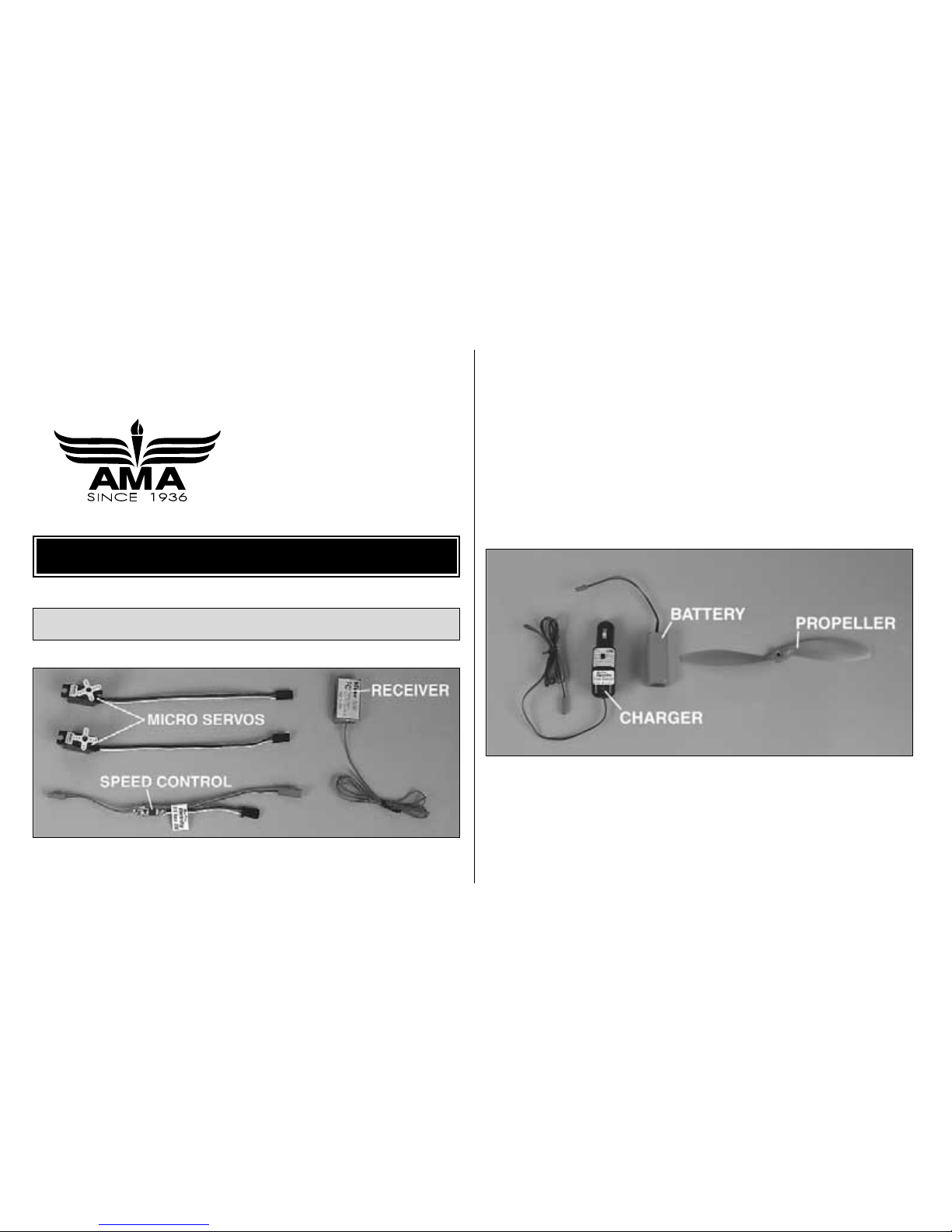
The Escapade requires a three-channel radio with two
micro servos, a receiver and a speed control. Hobbico®CS-5
Nano™servos (HCAM0090), the Hitec Feather receiver
(HRCL1535) and the Great Planes C-5 (GPMM2000) or
C-10 speed control (GPMM2010) are recommended. The
receiver comes without a crystal, which must be purchased
separately. The order number for the crystal is HRCL23**.
Substitute the “**” with the channel number you require. For
example, if the transmitter you plan to fly the Escapade with
is on channel 44, order receiver crystal HRCL2344.
Additionally, an 8-cell (7.2 volt) 150 to 350 mAh battery pack
(GPMP0050 – 150 mAh, shown in photo, GPMP0060 – 270
mAh, GPMP0070 – 350 mAh) and an APC 9 x 6 Slo-Flyer
propeller (APCQ5013) are required. For charging the
battery, the Great Planes ElectriFly Peak Charger
(GPMM3000) is recommended.
Flight Equipment
ADDITIONAL ITEMS REQUIRED
5
Page 6

In addition to common household tools, here is the list of
items used to build the Escapade.
❏ 30-minute epoxy (GPMR6047)
❏ 1/2 oz. Medium CA+ (GPMR6007)
❏ Hobby knife (HCAR0105)
❏ #11 blades (HCAR0211)
❏ Builder's triangle (HCAR0480)
❏ Drill and 1/16" drill bit
❏ Cellophane tape (for hinging elevator and rudder)
❏ Double-sided foam tape (GPMQ4440) for mounting
receiver and speed control
❏ Sandpaper and sanding block
❏ Soldering iron and electrical solder
❏ Modeling paint and paintbrush for painting pilot
(optional)
❏ Small Phillips screwdriver (#1)
❏ Small T-pins (HCAR5100) or craft pins
Building Supplies
6
1/64" = .4mm
1/32" = .8mm
1/16" = 1.6mm
3/32" = 2.4mm
1/8" = 3.2mm
5/32" = 4mm
3/16" = 4.8mm
1/4" = 6.4mm
3/8" = 9.5mm
1/2" = 12.7mm
5/8" = 15.9mm
3/4" = 19mm
1" = 25.4mm
2" = 50.8mm
3" = 76.2mm
6" = 152.4mm
12" = 304.8mm
15" = 381mm
18" = 457.2mm
21" = 533.4mm
24" = 609.6mm
30" = 762mm
36" = 914.4mm
Metric Conversions
To convert inches to millimeters, multiply inches by 25.4
Page 7
7
0" 1" 2" 3" 4" 5" 6" 7"
0 10 20 30 40 50 60 70 80 90 100 110 120 130 140 150 160 170 180
Inch Scale
Metric Scale
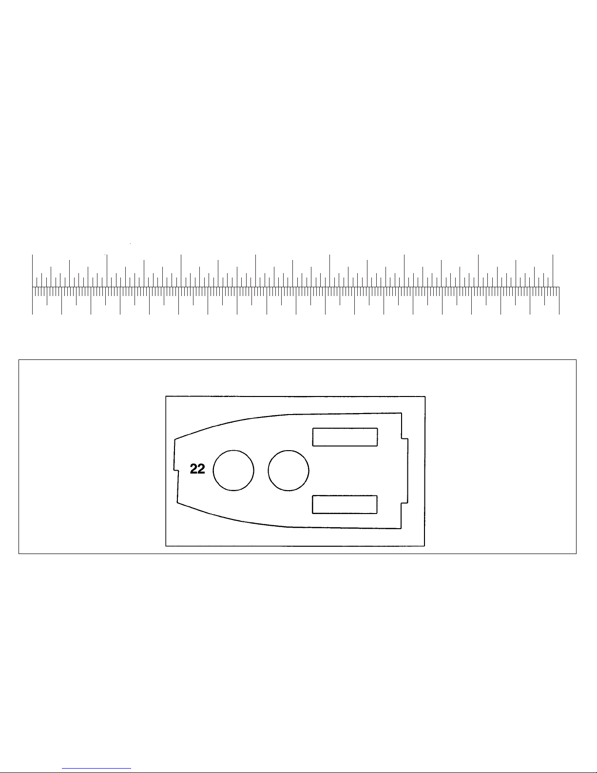
#22 Crutch
PARTS DRAWINGS (not actual size)
3/32" Balsa
Page 8
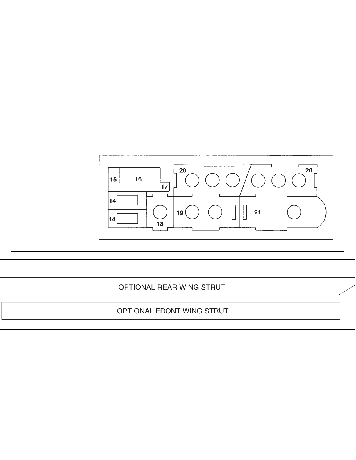
8
Optional Wing Struts (material not included, see page 21)
#14 Servo Trays (2)
Battery Holder Parts:
#17
#18
#19
#20 (2)
#21
Battery Holder Cover Parts:
#15
#16
3/32" Balsa
Page 9
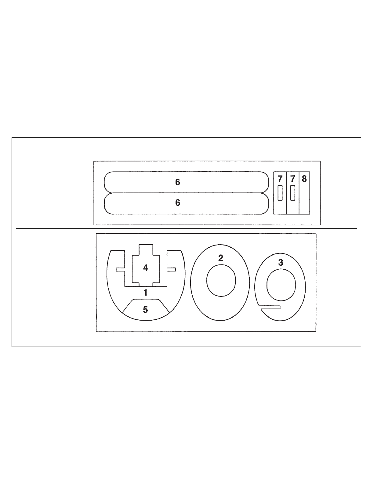
9
#6 Wing Braces (2)
#7 (2)
#8 Tab
3/32" Plywood
#1 Landing Gear Former
#2 Firewall
#3 Front Former
#4 (2)
#5 Retainer
1/32" Plywood
Page 10
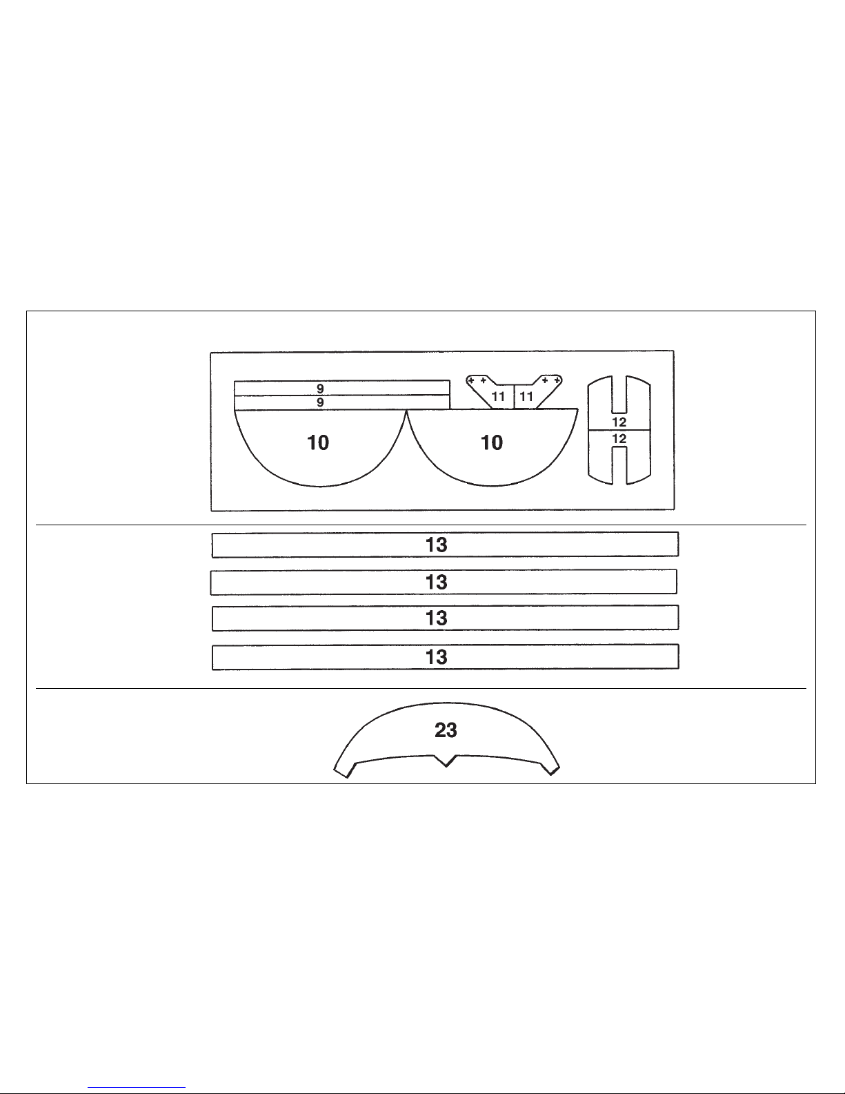
10
#9 Tail Struts (2)
#10 Doublers (2)
#11Control Horns (2)
#12 Spacers (2)
1/16" Balsa
#13 Wing Struts (4)
#23 Clear Plastic
Windscreen
1/32" Plywood
Page 11
• Since the Escapade is made mostly of foam, and since CA
adhesives commonly used to build R/C model airplanes
dissolve foam, CA should not be used when gluing foam
parts. Therefore, 30-minute epoxy, which is compatible with
foam, is used for most of the construction. Unless otherwise
specified in the instructions, 30-minute epoxy is to be used
for gluing all parts of the model together. There are a few
instances where CA may be used for gluing wood to wood.
• For the strongest bond apply epoxy to both parts being
joined.
• Before beginning construction, refer to the parts drawings
and use a ballpoint pen to write the part number on all the
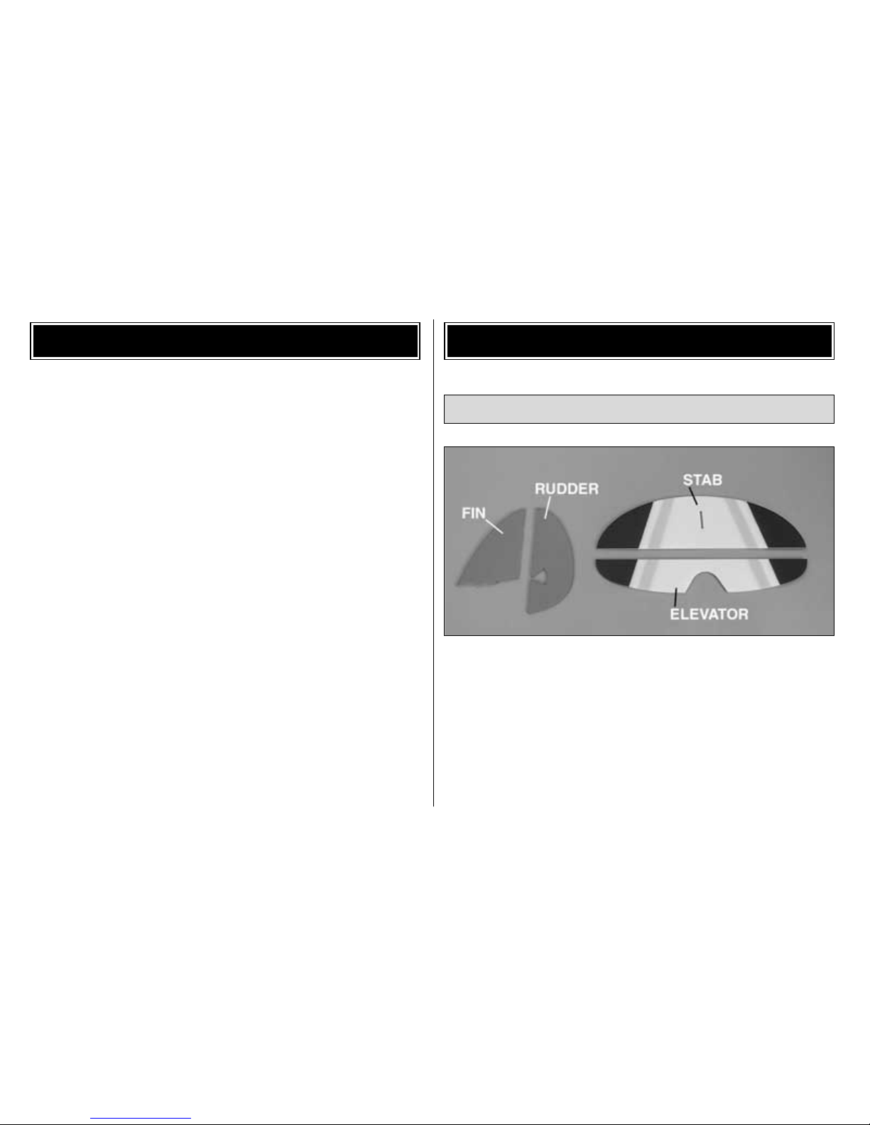
wood parts. ❏ 1. Using the precut lines as a guide, use a sharp hobby
knife to cut the rudder from the fin and the elevator from
the stabilizer (stab).
Assemble the Tail Surfaces
ASSEMBLYIMPORTANT BUILDING NOTES
11
Page 12
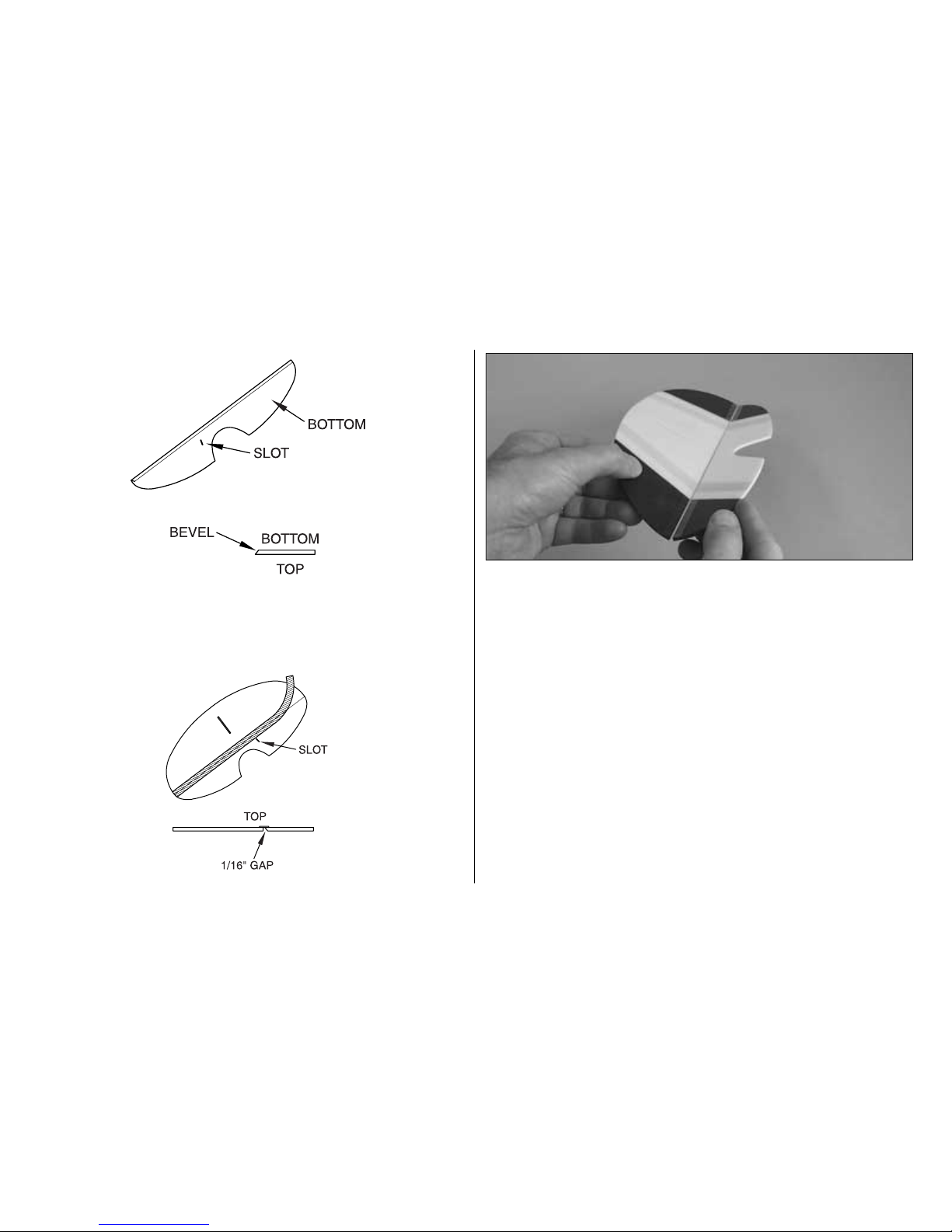
❏ 2. Sand a bevel to the bottom of the leading edge of the
elevator. The elevator is upside-down when the slot for the
control horn is on the left side.
❏ 3. Lay the stab and elevator on your workbench with the
slot in the elevator on the right side. Be certain there is a
1/16" gap between the elevator and the stab. Use one piece
of cellophane tape on the top to join the elevator to the stab.
❏ 4. Sand a bevel to one side of the rudder (it doesn't
matter which side), then use cellophane tape to join the
rudder to the fin just the same as you joined the elevator to
the stab.
❏ 5. Use a hobby knife to carefully widen the slot in the
rudder and the elevator for the 1/32" plywood control horns
(11). Only a small sliver of foam is to be removed.
12
Page 13

❏ 6. Glue the control horns into the slots. Be certain the
elevator control horn is on the bottom and the rudder
control horn is on the left (the stab and elevator are shown
upside-down in the photo). Also be certain the control horns
are facing forward.
❏ 7. Use epoxy to glue the fin to the stab. Use a small
builder's square to get the fin perpendicular to the stab, then
use tape or small T-pins to hold them together until the
epoxy hardens.
13
Page 14

❏ 1. Without using any glue, assemble all the 3/32" balsa
parts of the battery holder (7 x 2, 18, 19, 20 x 2, 21) as
shown in the sketch. Once all the parts are joined, use
medium CA to permanently hold them together.
❏ 2. Build the battery holder cover from the parts shown
in the photo (4, 15, 16). Before gluing on 16, sand the top of
15 and the bottom of 16 at an angle.
❏ 3. Fit the battery holder cover into the battery holder.
Glue the 1/32" plywood tab (8) and the tab mount (17) to
Assemble the Battery Holder
14
Page 15

the holder as shown. The tab will hold the cover in position,
until removal or installation of the battery is required.
❏ 1. Using the indentations in the aft end of the fuselage as
a guide, cut the slots for the elevator and rudder pushrods.
❏ 2. Temporarily fit the plywood landing gear former (1)
into the fuselage. Be certain it is centered and in the groove
in the fuselage. Use a fine-point felt-tip pen to mark the
inside of the fuselage on both sides of the opening in the
bottom of the landing gear former for the landing gear wires.
Assemble the Fuselage
15
Page 16

❏ 3. Remove the landing gear former. Cut a slot, centered
in the groove, from one mark to the other. Keep the piece of
foam that was removed from the slot you cut, so it can be
glued back into position after the former and the landing
gear have been installed.
❏ 4. Use medium CA to glue both 1/32" plywood doublers
(10) to both sides of F1.
❏ 5. Test fit the 1/8" plywood front former (3) into the front
of the fuselage. Trim the former as necessary, so it is even
with the front of the fuse. Note the position of the slot.
16
Page 17

❏ 6. Test fit the front former and the landing gear former to
the balsa crutch (22). Note that the tab on the front of the
crutch should be on the right side. Sand the front of the
crutch until it is the same width as the front former.
❏ 7.Test fit the crutch, the front former and the landing gear
former into the fuselage. The parts will have to be inserted
one at a time, then joined inside. Make adjustments as
necessary so the front former is even with the front of the
fuselage and the landing gear former rests in the groove.
❏ 8. Once you have fit all the parts into position,
permanently
glue them in place with 30-minute epoxy.
❏ 9. After the epoxy from the previous step has hardened,
glue the main landing gear wire and the plywood retainer
(5) into position. Before the epoxy hardens, fit the section of
foam that you removed back into the slot in the fuse.
17
Page 18

❏ 1. Install the pushrods and guide tubes into the
fuselage, but do not glue them into position until instructed
to do so. The pushrods cross inside the fuselage.
Refer to this sketch and the photo for the following
two steps.
❏ 2. Fit the servos into the balsa servo trays (14). Drill
1/16" holes through the trays, then mount the servos to the
trays with the screws that came with the servos.
❏ 3. Fit the servo trays with the servos into the crutch. Do
not glue the servo trays to the crutch until instructed to do
so. Connect the pushrods to the servos. If the pushrods do
not align with the servos, cut slots in the landing gear former
that will allow the pushrods to align as shown in the photo
and in the sketch.
Install the Servos
18
Page 19

❏ 1. Cut the slots in the wing for the wing struts.
❏ 2. Glue the 1/32" plywood wing braces (6) into the
indentations on the top of the wing.
❏ 3. Use a felt-tip pen to mark the center of the aft edge of
the opening in the wing. Place the wing on your workbench
resting on its trailing edge. Use a small builder's square to
mark a centerline on the wing from the mark you made
down to the TE.
Assemble the Wing
19
Page 20

❏ 4. Mark two additional lines 1-3/8" on both sides of the
centerline.
❏ 5. Slide the wing into the fuse until it is centered. When
the marks on the trailing edge of the wing and the opening
in the front of the wing are equally spaced between the
fuselage sides, the wing is centered. Test fit the battery
holder into fuse. If necessary, trim the edges of the opening
in the wing or sand the sides of the battery holder until it fits
in the fuse without disturbing the wing.
❏ 6. Glue the wing to the fuselage with 30-minute epoxy. If
necessary, use pins to hold it in place until the epoxy
hardens.
❏ 7. Use a hobby knife with a #11 blade to cut a small notch
for the wing struts in the bottom of the right side of the fuse
directly above the landing gear. Similarly, cut the slots in the
bottom of the wing at an angle to accommodate the top of
the wing struts.
20
Page 21

Optional slow-speed performance enhancement for
inexperienced pilots: To improve rudder control and stall
characteristics of the Escapade at slow speeds, use the
templates on page 8 to make the optional wing struts from
1/16" x 3/8" medium hardness balsa (not included). The
longer optional struts will increase the wing dihedral and
build in washout (an upward twist in the trailing edge of the
wing near the tips). This option is not necessary for
experienced pilots.
❏ 8. Trim the ends of two 1/16" balsa wing struts (13) to fit
the wing and fuse. Enlarge the slots if necessary. Cut the
bottom of the aft strut at an angle to fit the bottom of the
front strut. Permanently glue the struts into position.
❏ 9. Fit, then glue the wing struts to the other side of the
fuselage and the wing the same way.
❏ 1. Glue the stab and fin to the fuselage with 30-minute
epoxy. Make sure the fin is centered on the molded-in seam
on the top of the fuselage. Before the epoxy hardens, view
the wing and fuse from behind. If necessary, raise or lower
one side of the stab until it is parallel with the wing. Fill any
gaps between the fuse and the bottom of the stab with
additional epoxy. Use pins to hold the stab in position until
the epoxy has fully hardened.
Hook Up the Controls
21
Page 22

❏ 2. Connect the aft end of the pushrods to the control
horns on the elevator and rudder. If necessary, make small
bends in the pushrods to get them to align with the holes in
the horns. Be certain there is a small amount of sideways
tension in the rods so they remain connected to the horns.
❏ 3. Use a #11 blade to cut a slit in the center of the bottom
of the fuse and in the rudder to accommodate a hinge.
❏ 4. Use epoxy to glue the hinge into the slots you cut in
the rudder and the fuse.
❏ 5. Temporarily connect the speed control and servos to
the receiver. Connect the charged battery to the speed
control. Turn on the transmitter, then center the trims. If the
servo arms are not centered, remove the arms from the
servos and center the arms.
❏ 6. With the pushrods connected to the servos and the
control surfaces, position the servo trays so the elevator and
rudder are neutral. Carefully glue the servo trays to the
crutch.
22
Page 23

❏ 7. Now that the servos have been positioned and the
controls are centered, glue the ends of the pushrod guide
tubes to the slots in the fuselage and the slots in the landing
gear former.
❏ 8. The same as you mounted the balsa wing struts to the
wing, mount the plywood tail struts (9) to the bottom of the
stab and the fuse. Cut a small slot in the bottom of the fuse
to accommodate the ends of the struts, but do not cut slots
the stab. Glue the struts into position.
Refer to this photo for the following three steps.
❏ 1. Without using any glue, position the plywood firewall
(2) on the front former. If necessary, trim the firewall until it
matches the front of the fuselage. Glue the firewall into
position.
Mount the Motor
23
Page 24

❏ 2. Glue both 1/32" plywood spacers (12) to the firewall
as shown. Trim the top of the spacers even with the hole in
the firewall.
❏ 3. Position the wire nose gear on the firewall, then drill
1/16" holes for the screws. Mount the nose gear to the
firewall with two wood screws.
❏ 4. Without using tools, use your fingers to press the
motor all the way into the gearbox. Spin the shaft on the
gearbox. If there is resistance and the shaft does not spin
freely, back the motor out of the gearbox just enough to
allow the shaft to spin freely. Use a fine-point felt-tip pen to
mark the end of the gearbox onto the motor. This is how far
the motor is to be installed after the pinion gear is mounted.
❏ 5. Remove the motor from the gearbox.
❏ 6. The pinion gear fits onto the motor shaft easier one
way than it does the other. Using only your fingers (no tools),
determine which way is the easiest by test-fitting the gear
onto the shaft. The “easy way” is the way the gear goes on
and is to be permanently installed.
❏ 7. Remove the pinion gear from the motor. Add a small
drop of the cement included with this kit to the hole in the
end of the gear that fits onto the shaft. Install the gear onto
the shaft. The top of the gear should be even with the end of
the motor shaft.
❏ 8. Use a toothpick to apply a small dab of lubricating oil
to both ends of the motor shaft where it exits the motor. Do
not apply oil directly from the container because you may
apply too much.
24
Page 25

❏ 9. Reinstall the motor into the gearbox up to the line you
marked. Fit the prop adapter to the gearbox. Insert the
appropriate nylon spacer ring into the prop, then test fit the
prop to the gearbox (be certain to use the prop washer). If
necessary, use a hobby knife to enlarge the hole in the nylon
spacer ring so it will fit onto the prop adapter.
❏ 10. Tighten the prop nut with an 8mm wrench. If
necessary,
use a pliers to hold the drive washer while tightening the
prop. Wrap the drive washer with a cloth to keep the pliers
from marring it.
❏ 11. Spin the propeller by hand. It should spin somewhat
freely, but due to the resistance of the motor, the propeller
should not “coast” or freewheel indefinitely. If there is much
resistance, back the motor out of the gearbox the same as
you did before until the propeller spins as it should.
❏ 12. Remove the propeller from the gearbox. Position the
motor and gearbox on the firewall. Using the holes in the
mounting tabs on the gearbox as a guide, drill three 1/16"
holes through the firewall for the mounting screws. Mount
the gearbox to the firewall with three wood screws.
25
Page 26

❏ 1. Trim the excess material from the aft edge of the
molded plastic cowl. Cut a hole in the middle for the prop
shaft, then cut a slot for the nose gear.
❏ 2. Mount the cowl to the fuse with tape. Any kind of tape
will do, but we used 1/4" red striping tape. Mount the prop
adapter and prop to the gearbox. Note: If you are not able
to tighten the prop nut because the drive washer keeps
turning, remove the prop adapter assembly from the
gearbox. Tighten the prop to the adapter off of the gearbox.
Loosen the prop and separate the drive washer from the
adapter. Rejoin the assembly to the gearbox and tighten.
Final Assembly
26
Page 27

❏ 3. Cut six 1/8" retainers from the plastic tube. Mount the
wheels to the landing gear with a retainer on both sides of
each wheel. Using care not to get any glue on the wheels,
secure the retainers to the landing gear with medium CA.
❏ 4. Cutting along the molded-in lines, use small scissors
to cut out the two halves of the pilot. Note how the front half
of the pilot fits over the rear half.
❏ 5. Glue the pilot together. Glue the pilot to the battery
holder cover. You can cut a notch in the back of the pilot so
that he fits over the top of the cover, or simply glue him into
position resting on top. You may paint the pilot now, or wait
until the rest of the model is finished.
❏ 6. Test fit the clear plastic windscreen to the front of the
fuselage. Use a hobby knife with a #11 blade to make three
27
Page 28

small slits in the fuselage for the pointed tabs on the
windscreen, then glue it into position.
❏ 7. Use double-sided foam mounting tape (GPMQ4440) to
mount the speed control and receiver to the crutch inside
the fuselage. Be certain to mount them in a location that will
not interfere with the motor, servos or pushrods.
❏ 8. Route the receiver antenna out of the bottom of the
fuselage. Tape the antenna to the bottom of the aft end of
the fuselage. Never cut the antenna or coil it up. It is
tuned to a specific length. Be certain the antenna will not
interfere with the pushrods or come into contact with the
propeller.
IMPORTANT: Whenever connecting the battery always
hold onto the fuselage in case the motor accidentally
receives power and the propeller turns.
❏ 1. Turn on the transmitter and connect the battery to the
speed control in the model. Be certain the rudder, elevator
and motor respond as shown in the chart. If required, use
the reversing function in the transmitter to reverse any
controls necessary so they respond correctly.
❏ 2. Use the ATV function in the transmitter or adjust the
position of the pushrods on the servo arms or the control
Note: Unless you are specifically checking the operation of
the motor, for safety remove the propeller from the model
while setting it up on your workbench.
Set the Control Throws
PREPARE THE MODEL FOR FLYING
28
Page 29

horns on the elevator and rudder to get the control surface
throws shown in the chart that follows. The throws are
measured at the widest part of the control surface.
❏ 3. To increase the control surface throw, move the
pushrod
to the innermost hole of the control horn on the control
surface, or move the pushrod to the hole that is farther out
on the servo arm. To decrease the control surface throw, do
the opposite.
IMPORTANT: The C.G. (center of gravity), or balance point
has the greatest effect on how a model flies. Do not
overlook this important procedure. Modelers who do so
often find that the airplane is difficult to control, or out of
control after it is too late. Protect your model and insure that
the first flight won't be the last by balancing the model
according to the following instructions.
The C.G. (center of gravity) must be checked when the
model is ready to fly with the propeller and battery installed.
Balance the Model (C.G.)
Set up the Escapade so it has the following control surface
throws:
ELEVATOR: 5/8" [16mm] up
5/8" [16mm] down
RUDDER: 9/16" [14mm] right
9/16" [14mm] left
Second to the C.G., the control throws have the greatest effect
on the way a model flies. Set the throws as close to these
settings as possible. If you have too much control throw the
model may respond too quickly. If you do not have enough
throw you may not be able to maneuver the model or have
enough control to land it when the motor is off.
29
Page 30

❏ 1. Use a felt-tip pen or narrow strips of tape to mark the
balance point on the bottom of the wing 1-1/2" [38mm] from
the leading edge on both sides of the fuselage.
❏ 2. Lift the model right-side-up at the balance point you
marked on the bottom of the wing. If the nose drops, the
model is nose-heavy and you must add weight to the tail. If
the tail drops, the model is tail-heavy and you must add
weight to the nose. In some cases you can relocate the
receiver to achieve the correct balance without adding
additional weight.
❏ 3. If additional weight is required to balance the model,
use small pieces of Great Planes stick-on weight
(GPMQ4485). If weight is required in the nose, do not stick
weight to the cowl. Remove the cowl and stick the weight to
the firewall. If weight is required in the tail, it can be stuck to
the top or bottom of the stab next to the fuselage.
30
Page 31

❏ 4. After placing weight on the model where necessary,
recheck the C.G. to confirm that it is correct.
No matter if you fly at an AMA sanctioned R/C club site or
if you fly somewhere on your own, you should always have
your name, address, telephone number and AMA number
on or inside your model. It is required at all AMA R/C club
flying
sites and AMA sanctioned flying events. Fill out the
identification tag on page 39 and place it on or inside your model.
Be certain the transmitter batteries are fully charged. Follow
the battery charging instructions that came with your radio
control system to charge the batteries.
Before you fly you should perform one last overall
inspection to make sure the model is truly ready to fly and
that you haven't overlooked anything. If you are not
thoroughly familiar with the operation of R/C models, ask an
experienced modeler to perform the inspection. Check to
see that you have the radio installed correctly and that all
the controls are connected properly. The motor must also be
checked by confirming that the prop is rotating in the correct
direction and the motor sounds like it is reaching full power.
Make certain the elevator and rudder are secure, the
pushrods are connected, the controls respond in the correct
direction, radio components are securely mounted, and the
C.G. is correct.
Ground check the operational range of your radio before the
first flight of the day. With the transmitter antenna collapsed
and the receiver and transmitter on, you should be able to
walk at least 100 feet away from the model and still have
control. Have an assistant stand by your model and, while
you work the controls, tell you what the control surfaces are
doing. Repeat this test with the motor running at various
speeds with an assistant holding the model, using hand
signals to show you what is happening. If the control
surfaces do not respond correctly, do not fly! Find and
correct the problem first. Look for loose servo connections
or broken wires, corroded wires on old servo connectors,
poor solder joints in your battery pack or a defective cell, or
a damaged receiver crystal from a previous crash.
Range Check
Ground Inspection
Charge the Transmitter Batteries
Identify Your Model
31
Page 32

Use fine sandpaper to remove imperfections along the
edges of the propeller. For the best performance, use a Top
Flite Precision Magnetic Prop Balancer™(TOPQ5700) to
balance the propellers (this is a necessity on glow-powered
engines, but less critical on small electric models).
Using multiple battery packs for successive flights may
cause the motor to become excessively hot, thus causing
damage. Allow the motor to cool for at least 10 minutes
between flights.
Note: Failure to follow these safety precautions may result
in severe injury to yourself and others.
Get help from an experienced pilot when learning to
operate motors.
Use safety glasses when running motors.
Do not run the motor in an area of loose gravel or sand; the
propeller may throw such material in your face or eyes.
Keep your face and body as well as all spectators away
from the path of the propeller as you start and run the
motor.
Keep items such as these away from the prop: loose
clothing, shirt sleeves, ties, scarfs, long hair or loose objects
(pencils, screwdrivers) that may fall out of shirt or jacket
pockets into the prop.
The electric motor and motor battery used in the Escapade
are very powerful and the spinning propeller has a lot of
momentum; therefore, if you touch the propeller while it is
spinning it may inflict severe injury. Respect the motor and
propeller for the damage they are capable of and take
whatever precautions are necessary to avoid injury. Always
disconnect and remove the motor battery until you are
ready to fly again and always make sure the switches are
turned off before connecting the battery.
Read and abide by the following Academy of Model
Aeronautics Official Safety Code:
GENERAL
1. I will not fly my model aircraft in competition or in the
presence of spectators until it has been proven to be
airworthy by having been previously successfully flight
tested.
AMA SAFETY CODE (excerpt)
Motor Safety Precautions
Performance Tips
32
Page 33

2. I will not fly my model aircraft higher than approximately
400 feet within 3 miles of an airport without notifying the
airport operator. I will give right of way to and avoid flying in
the proximity of full-scale aircraft. Where necessary an
observer shall be utilized to supervise flying to avoid having
models fly in the proximity of full-scale aircraft.
3. Where established, I will abide by the safety rules for the
flying site I use and I will not willfully and deliberately fly my
models in a careless, reckless and/or dangerous manner.
7. I will not fly my model unless it is identified with my name
and address or AMA number, on or in the model.
RADIO CONTROL
1. I will have completed a successful radio equipment
ground
check before the first flight of a new or repaired model.
2. I will not fly my model aircraft in the presence of
spectators until I become a qualified flyer, unless assisted
by an experienced helper.
3. I will perform my initial turn after takeoff away from the pit,
spectator and parking areas and I will not thereafter perform
maneuvers, flights of any sort or landing approaches over a
pit, spectator or parking area.
4. I will operate my model using only radio control
frequencies currently allowed by the Federal
Communications
Commission.
Though the Escapade is a “Park Flyer,” the best place to fly
any model is at an AMA chartered club field. Club fields are
set up for R/C flying, making your outing safer and more
enjoyable. We recommend that you join the AMA and a local
club so you can have a safe place to fly and have insurance
to cover you in case of a flying accident. The AMA address
and telephone number are in the front of this manual.
If there is no club or R/C flying field in your area, find a
suitable site that is clear of trees, telephone poles,
buildings, towers, busy streets and other obstacles. Since
you are not flying at a sanctioned AMA site, be aware that
there may be others like yourself who could be flying
nearby. If both of your models happen to be on the same
frequency, interference will likely cause one or both of the
models to crash. An acceptable minimum distance between
flying models is five miles, so keep this in mind when
searching for a flying site.
In addition to obstacles, it is important to be aware of people
who may wander into the area once you begin flying. At
FIND A SAFE PLACE TO FLY
33
Page 34

AMA club flying sites it is a severe rule infraction to fly over
others, and this is a good practice if flying elsewhere. R/C
models tend to attract onlookers whose numbers can soon
multiply, forming small, uncontrolled crowds. Onlookers
pose two main problems. First is the danger of actually
crashing your model into a person, causing injury. Second
is the distraction from those who ask you questions while
you are trying to concentrate on flying. To minimize or avoid
this problem, have an assistant standing by who can spot
people who wander into your flying site (so you can avoid
flying over them) and who can perform “crowd control” if
people start to gather.
IMPORTANT: If you are an inexperienced modeler we
strongly urge you to seek the assistance of a competent,
experienced R/C pilot to check your model for airworthiness
AND to teach you how to fly. No matter how stable or
“forgiving” the Escapade is, attempting to learn to fly on
your own is dangerous and may result in destruction of your
model or even injury to yourself and others. Therefore, find
an instructor and fly only under his or her guidance and
supervision until you have acquired the skills necessary for
safe and fully controlled operation of your model.
We recommend flying the Escapade when the wind is no
greater than five miles per hour. Less experienced flyers
should fly the Escapade only in calm (less than one mile per
hour) conditions. Frequently, winds are calm in the early
morning and early evening. Often these are the most
enjoyable times to fly anyway!
Until you have the Escapade properly trimmed for level
flight, we recommend having an assistant hand-launch the
model instead of taking off from the ground.
Turn on the transmitter and plug the battery into the speed
control. Turn on the receiver by following the instructions
that came with your speed control.
IMPORTANT: Confirm that the transmitter operates the
controls by moving the sticks and watching the surfaces
respond. Occasionally, electric models have been launched
with the transmitter turned off or the battery disconnected
from the speed control!
When ready to launch, the assistant should hold the bottom
of the fuselage behind the main landing gear, then raise the
model high above his head and point it into the wind. With
Takeoff
FLYING
34
Page 35

the pilot
(that would be you!)
standing behind the plane, fully
advance the throttle to start the motor. As soon as the motor
is at full power, the hand launcher should gently toss the
plane into the air at a level or slightly nose-up attitude. Be
certain the model is being launched into the wind and be
immediately ready to make corrections to keep the airplane
flying straight, level and into the wind.
When the model has gained adequate flying speed under
its own power, gently pull the elevator stick back until the
airplane starts a gradual climb. Many beginners tend to pull
too hard causing the model to stall, so be gentle on the
elevator and don't panic. If you do pull too hard and you
notice the model losing speed, release the elevator stick
and allow the model to regain airspeed.
Continue a gradual climb and establish a gentle turn (away
from yourself) until the airplane reaches an altitude of 75 to
100 feet.
The main purpose of the first few flights is to learn how the
model behaves and to adjust the trims for level flight. After
the model has climbed to a safe altitude reduce the throttle
slightly to slow the model, yet maintain altitude. The
Escapade should fly well and maintain adequate airspeed
at about 1/2 to 3/4 throttle.
Adjust the elevator trim so the model flies level at the
throttle setting you are using. Adjust the rudder trim so the
model flies straight. It may take a few minutes to get the
trims adjusted, but this should be your first priority once at
a comfortable altitude. Continue to fly around, executing
turns and making mental notes (or having your assistant
take notes for you) of what additional adjustments or C.G.
changes may be required to fine tune the model so it flies
the way you like.
If the Escapade reaches a high enough altitude, you may
periodically cut off the motor power and glide. This may
extend the flight time by several minutes, especially if you fly
into a rising air current.
Because the Escapade flies slowly, it requires little room to
land. Begin the landing approach by flying downwind at an
altitude of approximately 20 feet [6 meters]. When the
airplane is approximately 50 to 100 feet [15 to 30 meters]
past you, gradually reduce power and make the “final”
Landing
Flight
35
Page 36

180-degree turn into the wind aligning the airplane with the
runway or landing area. Do not dive the airplane, as it will
pick up too much speed. Instead, allow the airplane to
establish a gradual descent. Concentrate on keeping it
heading into the wind toward the runway. When the plane
reaches an altitude of about 4 feet [1 meter], gently apply a
little “up elevator” to level the plane, but be careful as too
much up elevator will cause it to stall. While holding a slight
amount of up elevator the airplane will slow and descend as
it loses flying speed, thus touching-down on the runway.
Until you are able to accurately judge how far the Escapade
can glide, it may be helpful to reserve some battery power
to run the motor so the plane can be flown back to the
runway.
When speaking of small models, frequently a takeoff from
the ground is called a “ROG”
(rise off ground)
takeoff.
Landings on grass will be a little rough, but doing a ROG
takeoff from grass will probably not be possible with the
Escapade. If planning a ROG takeoff, find a paved surface.
After you have trimmed the Escapade for flight and have
become familiar with its flight characteristics, you may try
some ROG takeoffs. With the model on the runway and
pointing into the wind, gently apply power. Initially, the plane
may turn to the left or right because it has not gained
enough speed for the controls to become effective. Do your
best to get through this brief moment and maintain a
heading down the runway and into the wind. Make
corrections with the rudder to keep it rolling straight into the
wind. If the model veers too far off, cut the throttle and try
again. As the model begins to gain speed the controls will
become effective.
After the airplane has gained adequate speed (this requires
experience to gauge), gently pull back on the elevator stick
allowing the airplane to become airborne. Establish a gentle
climb the same as when you were hand-launching.
Best of luck and happy flying!
ROG (Rise Off Ground) Takeoff
36
Page 37

ElectriFly™C-10 Micro Ultra High Frequency Electronic
Speed Control
Its solid-state design enables the ElectriFly C-10 Micro to
offer a wide array of flight benefits in an incredibly compact,
ultralight package. Intended for loads of up to 12A and
motors up to 400-size, it features fully proportional forward,
brake, plus the throttle smoothness and extended run time
of high-frequency operation. Factory-installed radio and
battery connectors ease installation. A Safe-Start feature
prevents unintentional motor starts. Low voltage cut-off
reserves power for safe landing. Built-in BEC eliminates
unnecessary weight. 180-day warranty. GPMR2010
ElectriFly Sanyo®8-Cell, 150 N-Size NiCd Pack
Assembled with genuine Sanyo N-size NiCd cells, this
powerful pack weighs just 2.6 ounces and features a
preinstalled, 2-pin male connector for “plug in and fly”
simplicity. 1-year guarantee. Recharge with the ElectriFly
Peak Charger (GPMM3000). Note: If a peak charger is not
used, the pack must be charged at 45mA for 4-6 hours
before use. GPMP0050
OTHER ITEMS AVAILABLE FROM
GREAT PLANES
37
Page 38

ElectriFly Sanyo 8-Cell, 270mAh NiCd Pack
Compact but powerful, this ElectriFly battery pack arrives
assembled with connection lead and 2-pin connector. Best
of all, it adds only 3.7 ounces of weight to your park flyer
model! 1-year guarantee. Recharge with an AC overnight
charger at 50mA rate, or use the ElectriFly Peak Charger
(GPMM3000). GPMP0060
ElectriFly Sanyo 8-Cell, 350mAh NiCd Pack
Its higher 350mAh capacity means more flight time – but
this ElectriFly NiCd pack remains featherlight at just 3.8
ounces, and continues the advantages of having Sanyo
cells, preinstalled connectors, and a 1 year guarantee.
Recharge with an AC overnight charger at 50mA rate, or
use the ElectriFly Peak Charger (GPMM3000). GPMP0070
38
Page 39

ElectriFly Peak Charger
Designed for small, lightweight electrics and transmitter
batteries, this charger can also be used with any 6- 8-cell
NiCd or NiMH pack. It plugs into a power supply or cigarette
lighter for fast charges. Pulsed current charging protects
small packs from overheating. Charge rate adjusts to 200
mAh or 600mAh. A 15mA trickle charge keeps packs topped
off for use anytime. Includes 2-pin connector for ElectriFly
packs; adapters available separately. 1-year warranty.
GPMM3000
IDENTIFICATION TAG
Photocopy this tag
39
Page 40

FLIGHT LOG
BUILDING NOTES
Kit Purchased Date: _______________________
Where Purchased:_________________________
Date Construction Started: __________________
Date Construction Finished: _________________
Finished Weight: __________________________
Date of First Flight: ________________________
 Loading...