

Page 1
TM
®
®
®
INSTRUCTION MANUAL
SPECIFICATIONS
Wingspan:
37 in
[940 mm]
Wing Area: 286 in
2
[18.4 dm2]
WARRANTY
Great Planes® Model Manufacturing Co. guarantees this kit to
be free from defects in both material and workmanship at the
date of purchase. This warranty does not cover any component
parts damaged by use or modification. In no case shall Great
Planes’ liability exceed the original cost of the purchased kit.
Further, Great Planes reserves the right to change or modify this
warranty without notice.
In that Great Planes has no control over the final assembly or
material used for final assembly, no liability shall be assumed nor
accepted for any damage resulting from the use by the user of
the final user-assembled product. By the act of using the
user-assembled product, the user accepts all resulting liability.
If the buyer is not prepared to accept the liability associated
with the use of this product, the buyer is advised to return
Weight:
Wing
Loading:
8.5– 10 oz
[240–285 g]
4.3 – 5.0 oz/ ft
[13– 15 g /dm2]
Length: 30 in [760mm]
Radio: 4-channel, 3 micro servos
2
Motor: RimFire
™
250
outrunner brushless motor
this kit immediately in new and unused condition to the
place of purchase.
To make a warranty claim send the defective part or item to
Hobby Services at the address below:
Hobby Services
3002 N. Apollo Dr. Suite 1
Champaign IL 61822 USA
Include a letter stating your name, return shipping address, as
much contact information as possible (daytime telephone
number, fax number, e-mail address), a detailed description of
the problem and a photocopy of the purchase receipt. Upon
receipt of the package the problem will be evaluated as quickly
as possible.
READ THROUGH THIS MANUAL BEFORE STARTING CONSTRUCTION. IT CONTAINS IMPORTANT
INSTRUCTIONS AND WARNINGS CONCERNING THE ASSEMBLY AND USE OF THIS MODEL.
© 2010 Hobbico®, Inc. GPMA1940 Mnl
Champaign, Illinois
(217) 398-8970, Ext 5
airsupport@greatplanes.com
Page 2
INTRODUCTION
AMA
INTRODUCTION . . . . . . . . . . . . . . . . . . . . . . . . . . . . . . . . 2
AMA . . . . . . . . . . . . . . . . . . . . . . . . . . . . . . . . . . . . . . . . . . 2
SAFETY PRECAUTIONS . . . . . . . . . . . . . . . . . . . . . . . . . 2
ADDITIONAL ITEMS REQUIRED . . . . . . . . . . . . . . . . . . .3
Radio Equipment . . . . . . . . . . . . . . . . . . . . . . . . . . . . .3
Motor, Battery, ESC . . . . . . . . . . . . . . . . . . . . . . . . . . .3
Battery Charging Equipment . . . . . . . . . . . . . . . . . . . . 3
Adhesives and Building Supplies. . . . . . . . . . . . . . . . . 3
KIT INSPECTION. . . . . . . . . . . . . . . . . . . . . . . . . . . . . . . . 3
KIT CONTENTS. . . . . . . . . . . . . . . . . . . . . . . . . . . . . . . . . 4
ASSEMBLE THE FUSELAGE . . . . . . . . . . . . . . . . . . . . . . 5
Install the Horizontal and Vertical Stabilizer . . . . . . . . . 5
Install the Elevator and Rudder Servos . . . . . . . . . . . . 6
Mount the Motor. . . . . . . . . . . . . . . . . . . . . . . . . . . . . . 7
Hook up the Elevator and Rudder . . . . . . . . . . . . . . . . 8
ASSEMBLE THE WING . . . . . . . . . . . . . . . . . . . . . . . . . . . 9
Hook up the Ailerons . . . . . . . . . . . . . . . . . . . . . . . . . . 9
Finish the Wing . . . . . . . . . . . . . . . . . . . . . . . . . . . . . . 9
GET THE MODEL READY TO FLY . . . . . . . . . . . . . . . . . 11
Check the Control Throws . . . . . . . . . . . . . . . . . . . . . 11
Balance the Propeller. . . . . . . . . . . . . . . . . . . . . . . . . 12
Balance the Model (C.G.). . . . . . . . . . . . . . . . . . . . . . 12
Charge the Batteries . . . . . . . . . . . . . . . . . . . . . . . . .13
MOTOR SAFETY PRECAUTIONS . . . . . . . . . . . . . . . . . 13
FLYING. . . . . . . . . . . . . . . . . . . . . . . . . . . . . . . . . . . . . . . 13
Mount the Wing . . . . . . . . . . . . . . . . . . . . . . . . . . . . . 13
Ground Check and Range Check . . . . . . . . . . . . . . .13
Flight . . . . . . . . . . . . . . . . . . . . . . . . . . . . . . . . . . . . . 13
C.G. Template . . . . . . . . . . . . . . . . . . . . . . . . . . . . . . . . . 15
INTRODUCTION
Thank you for purchasing the Carl Goldberg Classics EP
Falcon ARF. Anyone who remembers the Carl Goldberg line will
have fond memories of the Falcon series—many of you have
probably built a Falcon as a young modeler. For those of you
who do not know of the Falcon, hopefully you will experience the
same enjoyment as many others before you. Even without the
nostalgia the Falcon stands on its own! Interestingly, this new
EP Falcon is basically the same size as the original JR. Falcon.
The EP Falcon was originally intended for indoor fl ight, but
we found that in the right conditions (low winds) the Falcon
is just as much fun outdoors! And the steerable nose wheel
adds even more to the fun and practicality.
For the latest technical updates or manual corrections to the
EP Falcon visit the Great Planes web site at www.greatplanes.
com. Open the “Airplanes” link, then select the Carl Goldberg
Classics EP Falcon. If there is new technical information or
changes to this model a “tech notice” box will appear in the
upper left corner of the page.
If you are not already a member of the AMA, please join! The
AMA is the governing body of model aviation and member-
ship provides liability insurance coverage, protects modelers’
rights and interests and is required to fly at most R/C sites.
ACADEMY OF MODEL AERONAUTICS
5151 East Memori al Drive
Muncie, IN 47302-9252
Tele. (800) 435-9262
Fax (765) 741-0057
Or via the Internet at:
http://www.modelaircraft.org
http://www.modelaircraft.org/parkfl yer.aspx
IMPORTANT!!! Two of the most important things you can do
to preserve the radio controlled aircraft hobby are to avoid
fl ying near full-scale aircraft and avoid fl ying near or over
groups of people.
SAFETY PRECAUTIONS
Protect Your Model, Yourself & Others …
Follow These Important Safety Precautions
1. Your EP Falcon should not be considered a toy, but rather a
sophisticated, working model that functions very much like
a full-size airplane. Because of its performance capabilities,
the Falcon, if not assembled and operated correctly, could
possibly cause injury to yourself or spectators and damage
to property.
2. You must assemble the model according to the
instructions. Do not alter or modify the model, as doing
so may result in an unsafe or unfl yable model. In a few
cases the instructions may differ slightly from the photos.
In those instances the written instructions should be
considered as correct.
3. You must take time to build straight, true and strong.
4. You must use an R/C radio system that is in good condition,
a correctly sized engine, and other components as specifi ed
in this instruction manual. All components must be correctly
installed so that the model operates correctly on the ground
and in the air. You must check the operation of the model
and all components before every fl ight.
5. If you are not an experienced pilot or have not fl own this
type of model before, we recommend that you get the
assistance of an experienced pilot in your R/C club for
your fi rst fl ights. If you’re not a member of a club, your
local hobby shop has information about clubs in your area
whose membership includes experienced pilots.
6. While this kit has been fl ight tested to exceed normal use,
if the plane will be used for extremely high stress fl ying,
such as aggressive aerobatics, or if a motor larger than
one in the recommended range is used, the modeler is
responsible for taking steps to reinforce the high stress
points and/or substituting hardware more suitable for the
increased stress.
2
Page 3
We, as the kit manufacturer, provide you with a top quality,
thoroughly tested kit and instructions, but ultimately the
quality and fl yability of your fi nished model depends
on how you build it; therefore, we cannot in any way
guarantee the performance of your completed model,
and no representations are expressed or implied as to the
performance or safety of your completed model.
Remember: Take your time and follow the instructions
to end up with a well-built model that is straight and true.
ADDITIONAL ITEMS REQUIRED
This is a partial list of items required to fi nish the EP Falcon
that are illustrated in the instruction manual. Order numbers
are provided in parentheses.
Radio Equipment
4-channel radio control system
❍
Three micro servos such as ElectriFly
❍
servos (GPMM1200)
Mini/micro receiver (Futaba
❍
Futaba AEC-27 J-series servo extension (for aileron
❍
servo—FUTM3909)
®
R6004FF – FUTL7624)
®
ES40 Pico
Battery Charging Equipment
A LiPo-capable battery charger and a power source for the
battery charger is required. Virtually all suitable battery
chargers can be powered by a 12V battery, but it is more
convenient to use a charger that can be connected either
to a 12V battery (for charging at the fl ying fi eld) or to a 110V
wall outlet (for charging at home). One suitable LiPo charger
is the Great Planes ElectriFly Triton EQ™ AC/DC Charger
(GPMM3155). And in addition to its LiPo capability, the Triton
EQ also features one more critical component, which is a
built-in LiPo cell balancer. For the best LiPo performance,
longevity and safety, a LiPo cell balancer must be used so
each individual cell in the LiPo battery can be charged evenly.
Another suitable LiPo battery charger is the Great Planes
PolyCharge4™ DC LiPo charger (GPMM3015). The advantage
of the PolyCharge4 is that it can charge up to four LiPo batteries
at the same time. But unlike the Triton EQ, the PolyCharge4
does not have an internal LiPo cell balancer, so for each LiPo
battery you wish to charge simultaneously (up to 4), one Great
Planes Equinox™ LiPo Cell Balancer (GPMM3160) will be
required. Finally, the PolyCharge4 does not have AC capability,
so if wall-charging from home is a priority a separate A/C 12Volt power source must be purchased separately. A suitable
power supply then for the PolyCharge4 is the Great Planes
12V 12A DC power supply (GPMP0901).
Motor, Battery, ESC
Great Planes RimFire
❍
(GPMG4502)
Great Planes ElectriFly 2S (7.4V) 300mAh 20C
❍
Competition BP LiPo battery (GPMP0700)
Great Planes ElectriFly SS-8 8 Amp Brushless ESC
❍
(electronic speed control) (GPMM1800)
APC 8 x 3.8 Slo-Flyer electric propeller (APCQ5000)
❍
(At least one spare propeller in your fl ight box is also
recommended.)
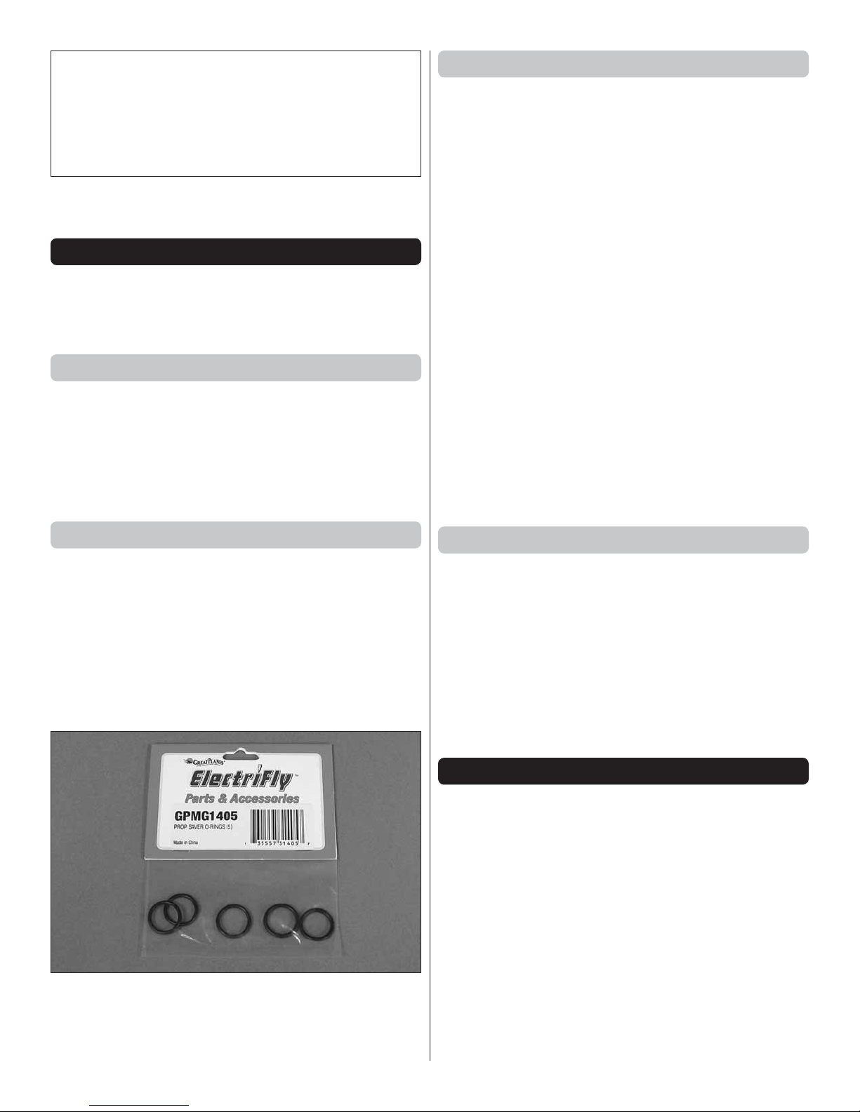
It is also highly recommended that you stock up on spare
propeller saver O-rings (GPMG1405).
™
250 Outrunner motor
Adhesives and Building Supplies
Other than common hobby tools, this is the list of Adhesives
and Building Supplies that were used to fi nish the EP Falcon.
Thin, foam-safe CA (HOTR1040)
❍
CA applicator tips (GPMR6033)
❍
CA accelerator (GPMR6035)
❍
Great Planes Pro
❍
Optional: Clear or white RTV silicone adhesive or
❍
J&Z R/C 56 Canopy Glue (JOZR5007)
™
Threadlocker (GPMR6060)
KIT INSPECTION
Carefully remove the major parts from the kit. Take an inventory
to make sure it is complete, and inspect the parts to make
sure they are of acceptable quality. If any parts are damaged
or missing or are not of acceptable quality, or if you need
assistance with assembly, contact Product Support. When
reporting defective or missing parts, use the part names
exactly as they are written in the Kit Contents list.
Great Planes Product Support
3002 N Apollo Drive, Suite 1
Champaign, IL 61822
Ph: (217) 398-8970, ext. 5
Fax: (217) 398-7721
E-mail: airsupport@greatplanes.com
3
Page 4
12
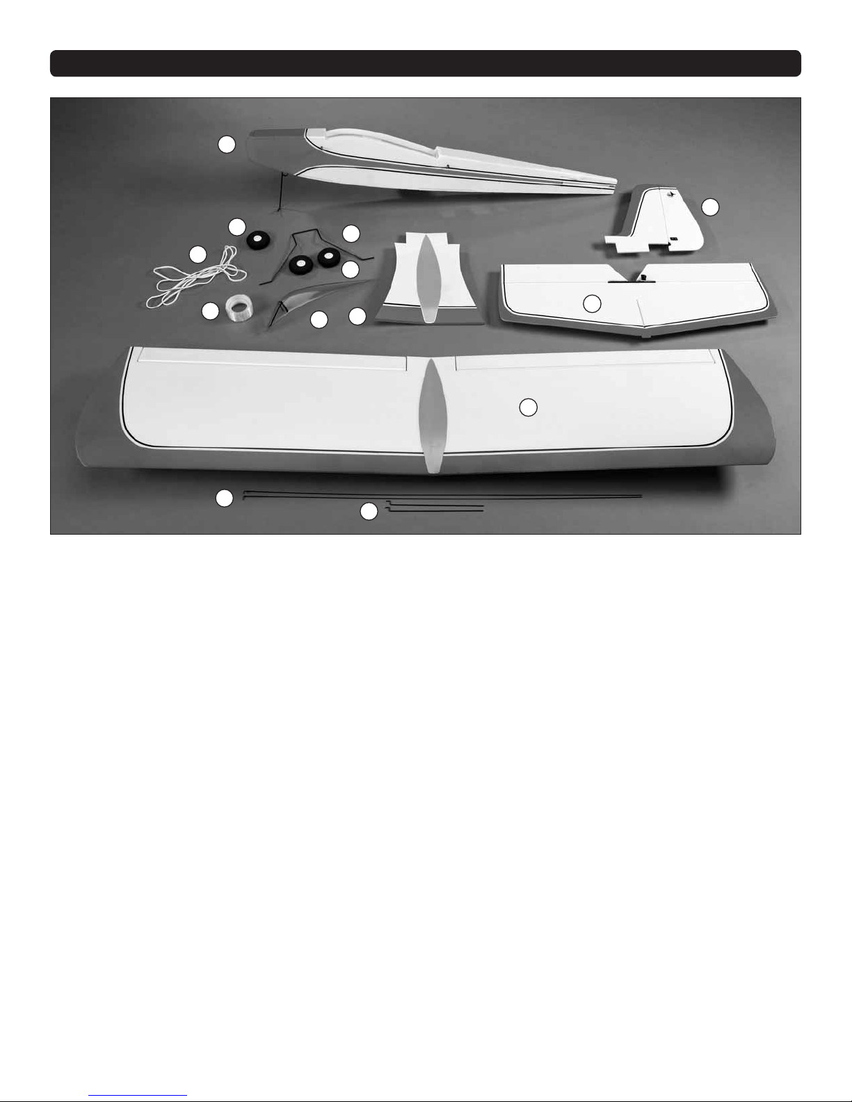
KIT CONTENTS
1
2
11
10
9
13
6
1. Fuselage
2. Vertical Stabilizer
3. Horizontal Stabilizer
4. Wing
5. Aileron Pushrods
6. Rudder/Elevator Pushrods
7. Wing Center Doubler
7
8
5
3
4
8. Canopy
9. Main Wheels
10. Main Landing Gear
11. Nose Wheel
12. Rubber Bands
13. Fiber Reinforcement Tape
4
Page 5
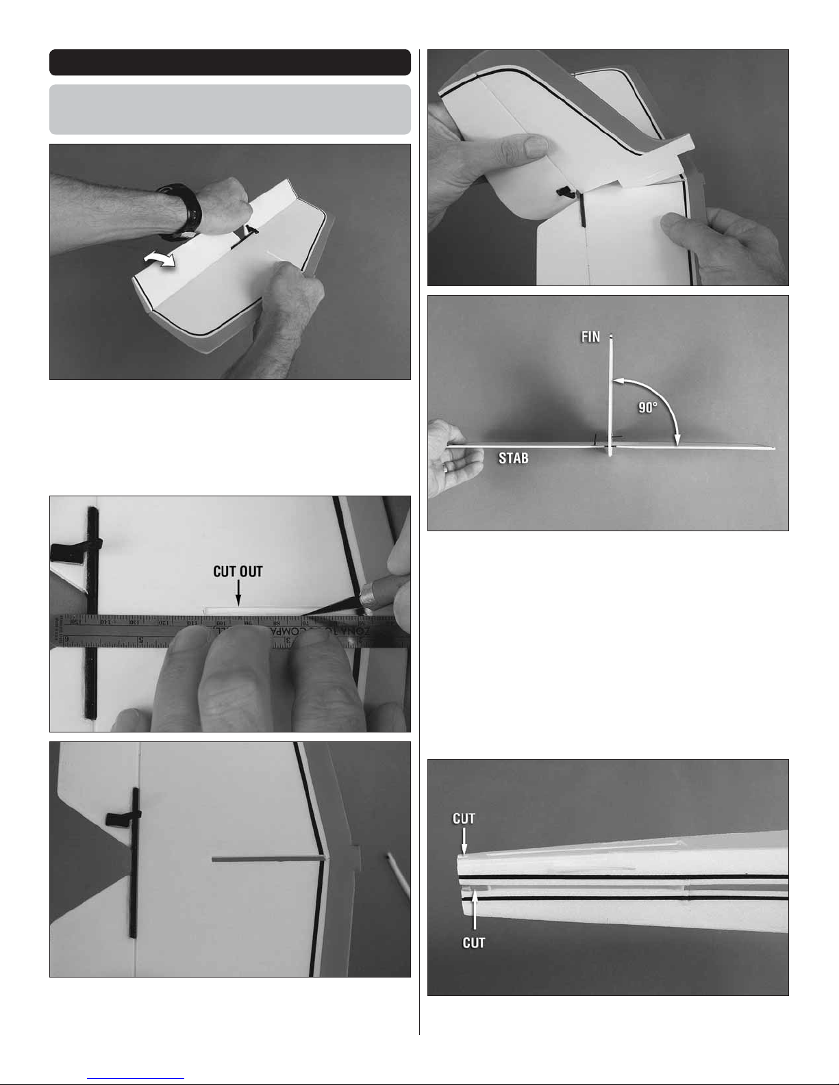
ASSEMBLE THE FUSELAGE
Install the Horizontal and
Vertical Stabilizer
1. Carefully fl ex the elevator up and down several times to
❏
loosen the hinge.
3. Test fi t the fi n into the stab. Lightly spray the parts where
❏
they fi t together with a mist of CA accelerator and allow to dry
for about 30 seconds to a minute. This “priming” procedure will
allow the CA to harden quickly when gluing the parts together.
Using a builder’s square to make sure the fi n and stab are
perpendicular, use a small amount of thin, foam-safe CA
to glue them together—do not saturate the foam or build up
large fi llets of glue—this could damage the foam and will add
unnecessary weight!
2. Use a straightedge and a hobby blade to fi nish cuttting
❏
out the slot in the horizontal stabilizer (stab) for the vertical
stabilizer (fi n).
4. Cut the spacers from the slot on both sides and on the
❏
top of the fuselage for the fi n and stab.
5
Page 6

5. Carfully fi t the stab/fi n into the fuselage. Make sure the
❏
bottom of the fi n is fully keyed into the slot in the bottom of
the fuselage and that the tab in the front of the stab is keyed
into the slot in the former.
9. Carefully insert the main landing gear into the fuselage—
❏
note that the legs sweep aft.
Install the Elevator & Rudder Servos
ES40 Pico Servos
6. Use small pins to hold the fuselage sides to the fi n and stab.
❏
7. Temporarily mount the wing to the fuselage with a couple
❏
of rubber bands. View the plane from behind to make sure the
stab is level with the wing. If necessary, add a small amount
of weight (1/4 – 1/2 oz.) to the “high side” of the stab to get
the alignment.
8. Using the pins and your fi ngers to hold the fuselage to
❏
the fi n and stab, permanently glue the stab/fi n into position
with thin, foam-safe CA—again, use only a small amount
of glue, allowing it to “wick” into the foam along the seam.
Remove the pins.
Cut
1. Make two single-arm servo arms by cutting off one of
❏
the longer arms.
Outer/inner holes
Screw-lock
connector
Retainer
2. If necessary, use a #55 (.052” [1.2mm]) drill or a #11
❏
blade to enlarge the holes in the servo arms so the screw-
lock connectors will fi t. Mount a screw-lock connector to the
outer and inner holes of one servo arm and to the middle
hole of the other servo arm.
It will be easier to mount the servo arms to the servos
now, before installing the servos in the fuselage.
3. Temporarily connect the elevator and rudder servos and
❏
your ESC to your receiver. Turn on your transmitter. While the
transmitter is on, go ahead and take a second to reverse the
aileron, elevator and throttle channels.
Make two
Middle hole
6
Page 7

No Yes
of the two balsa servo trays fi ts your servos. Add a small drop
of CA to the tips of the screws where they come through the
bottom of the servo tray.
Pressed all the way down
6. Fit, then glue the servo tray into position—although the
❏
parts you are gluing here are balsa and regular CA could be
used, foam-safe CA is still recommended.
4. Center the trims and connect a battery to the ESC to
❏
power the system up. Mount the servo arms 90°—or as close
to 90° as you can get—to the servos and install the servo
screws. Be certain the servo arms are all the way down on
the toothed output shafts before installing the screws.
5. Disconnect the servos and the ESC from the receiver.
❏
Use the tiny wood screws included with this kit or the screws
included with your servos to mount the servos to whichever
Mount the Motor
NO!
Gap
YES!
No gap
1. If using the recommended APC 8 x 3.8 Slow-Flyer
❏
propeller, install the larger I.D. spacer ring that came with
the propeller into the back of the propeller hub. Reinstall the
propeller adapter on the RimFire 250 motor so the propeller
will mount on the large end of the adapter—don’t forget to
use a tiny drop of threadlocker on the threads of the adapter
screws. Note: If the heads of the adapter screws interfere
with the base of the propeller hub not allowing the hub to lie
fl at and square, carefully chamfer the base of the hub just
enough to clear the screws.
7
Page 8

Refer to this photo for the following three steps.
2. With the ESC connected to the receiver, guide the three
❏
motor wires from the ESC down through the fuselage and
through the curved slot for the wires in the back of the fi rewall.
Connect the wires to the motor.
3. Before mounting the propeller, connect the motor and a
❏
battery to the ESC. Make sure the throttle channel is reversed,
then use the radio to run the motor to make sure it is turning
in the correct direction (counter-clockwise when viewed from
the front). If the motor is not turning the correct direction, swap
any of the two motor/ESC wires with each other to make the
motor turn the right way.
4. The propeller may be mounted to the motor later, but it
❏
is easier to do now, before the motor has been mounted to
the fuselage. If you mount the propeller now, fi rst balance it
as instructed on page 12.
5. Mount the motor to the fi rewall with the three 2mm x
❏
8mm washer-head Phillips screws.
6. Coil up the rest of the motor wires and place the ESC
❏
and the wire in the fuselage behind the fi rewall. Hold it to
the inside of the fuselage with Velcro® or double-sided foam
mounting tape.
8. Mount the receiver to the bottom of the servo tray with
❏
Velcro or double-sided foam adhesive tape.
9. Apply a 1/4" [6mm] strip of the softer “loop” side of the
❏
adhesive-backed Velcro material to your battery and mount it to
the “hook” side of the Velcro already in the nose of the fuselage.
Hook Up the Elevator and Rudder
1. Guide the elevator and rudder pushrods up through
❏
the guide tubes in the fuselage. Connect the pushrods to
the middle holes in the rudder and elevator horns with the
90-degree pushrod connectors. (It may be necessary to slightly
enlarge the holes in the horns with a hobby knife to get the
pushrods to fi t—but be careful—don’t oversize the holes. Just
a few twists of the blade should do it.)
7. Guide the servo and ESC wires out through the lightening
❏
hole in the bottom of the fuselage just ahead of the landing
gear. Then, connect the wires to the receiver. Also connect
a 6" [150mm] servo extension wire to the aileron channel in
the receiver.
2. With the radio on and the trims centered, lock the
❏
elevator, rudder and nose-steering pushrods into the screw-
lock connectors by tightening the screws—don’t forget to use
a small drop of threadlocker on the threads of the screws and
make sure each control is centered when tightening the screws.
3. With the radio on, roll the fuselage along the fl oor to see if
❏
it goes straight. If necessary, adjust the nose-steering pushrod
in the screw-lock connector to get the model to roll straight.
8
Page 9

ASSEMBLE THE WING
Hook Up the Ailerons
Servo arm that
came with servo
1.0mm screws
Offset servo arm
1. Use two of the tiny wood screws included with this kit
❏
to mount the offset aileron servo arm to the bottom of the
aileron servo arm that came with your servo. Also add a few
drops of thin CA around the edges of the servo arm to securely
glue the two arms together.
up through the holes in the offset servo arm. Mount it to the
servo with the servo arm screw.
5. Insert the pushrods into the screw-lock connectors on
❏
the aileron horns. With the radio on and the servo centered,
center each aileron and tighten the screw in the screw-lock
connector to lock the pushrods down—don’t forget to add a
small drop of threadlocker on the threads of the screws.
Finish the Wing
The wing may be fi nished in either of two confi gurations: one
for indoor fl ying and another for outdoor fl ying. Of course, if
you prep the wing for outdoor fl ight it may still be fl own indoors,
but the Falcon will be slightly heavier and may not allow you
to take full advantage of its absolute slowest fl ight possibilities.
The “indoor” wing may also be fl own outdoors, but care should
be taken not to overstress the wing by performing aggressive
aerobatics or fl ying on windy days.
Perform steps 1, 2 and 3 only if
building the outdoor wing.
2. Flex the ailerons up and down several times to break
❏
them in so they will be easier to move with the servo.
Refer to this photo for the rest of the
steps to hook up the ailerons.
3. Mount the aileron servo in the wing using the screws
❏
included with this kit or the screws that came with the servo.
4. Same as was done for the elevator and rudder, temporarily
❏
connect the aileron servo to the receiver and power up the
system so you can center the servo. Slip the aileron pushrods
1. If building the outdoor wing, test-fi t the plastic wing
❏
center doubler to the top of the wing just to see how it fi ts
before removing the protective backing from the adhesive
tape on the bottom—the best way to fi t the doubler is fi rst to
center the “lip” on the back over the trailing edge of the wing
between the ailerons, then “roll” and press the doubler forward.
2. Now that you have practiced installing the doubler, remove
❏
the backing from the tape on the bottom and carefully apply
the doubler to the wing.
3. Cut the included fi ber-reinforced tape into one 24"
❏
[610mm] piece and into one 18" [460mm] piece. Attach the
strips to the bottom of the wing where shown.
9
Page 10

front of the template with the leading edge. Use a fi ne-point
felt-tip pen to mark the ends of the C.G. lines on the template
onto the wing.
6. Use a straightedge to draw lines connecting the dots
❏
depicting the recommended balance range.
4. If building the indoor wing, simply stick the plastic rubber
❏
band protectors to the top of the wing at the leading and
trailing edges where shown.
7. Finally, apply narrow strips of tape over the lines so you
❏
will be able to feel them with your fi ngers when balancing the
model later.
5. Cut the C.G. Marking Template from the back of the
❏
manual and place it on the bottom of the wing, aligning the
8. Use a dab of RTV silicone or white glue to glue the pilot
❏
into position directly on top of the wing or to the doubler (if
building the outdoor wing) 2-1/8” [54mm] from the leading edge.
10
Page 11

9. Use a few dabs of clear RTV silicone, R/C 56 canopy
❏
glue or double-sided adhesive tape to hold the canopy to the
top of the wing or to the doubler. Note: Non-permanent glue
is recommended to allow for easy removal of the canopy in
the future.
GET THE MODEL READY TO FLY
Check the Control Throws
If the pushrods were connected to the servo arms as
previously illustrated, then the control throws should already
be correct, or very nearly correct. However, it is still a good
idea to check the throws since they have such a great effect
on how the model fl ies.
1. Make sure the throttle stick is all the way down so
❏
you do not accidentally arm or start the motor. Turn on your
transmitter and connect a battery to the ESC.
4. Use the transmitter to move the elevator to full “up” and
❏
note how far the elevator moved. This is the “up” elevator throw.
On the servo, move the pushrod out to increase throw,
or in to decrease throw.
2. Make sure the ailerons, elevator and rudder are centered.
❏
If necessary, adjust the pushrods in the screw-lock connectors
to center the controls and re-tighten the screws in the
screw-locks.
Measure the elevator throw fi rst…
3. Hold a ruler to the trailing edge of the elevator. Note the
❏
measurement.
More throw
On the control surface,
move the pushrod in to increase throw,
or out to decrease throw.
Less throw
5. Make sure the up elevator throw you measured is the
❏
same as the throw specifi ed on the following page. Measure
the down elevator throw and the rudder and aileron throw the
same way for both the high and low rates. If the throws on your
plane are within 1/8" [3mm] of the specifi ed throws, go ahead
and fi ne-tune the throws using the End Point adjustments
in your transmitter. If the throws are too far off, change the
throws by relocating the pushrods on the servo arms and/or
control horns on the surfaces. Moving the pushrods inward
on the servos or outward on the control surfaces will provide
less throw and moving the pushrods outward on the servos
or inward on the control surfaces will provide more throw.
11
Page 12

These are the recommended control surface throws:
HIGH RATE LOW RATE
Down
3/8"
[10mm]
ELEVATOR
Up
3/4"
[19mm]
28°
Down
5/8"
[16mm]
23°
Up
1/2"
[13mm]
13°
14°
Balance the Model (C.G.)
More than any other factor, the C.G. (center of gravity/balance
point) can have the greatest effect on how a model fl ies. If
you value your model and wish to enjoy it for many fl ights,
DO NOT OVERLOOK THIS IMPORTANT PROCEDURE.
A model that is not properly balanced may be unstable and
possibly unfl yable.
RUDDER
AILERONS
Right
1-1/2"
[38mm]
35°
Up
1/2"
[13mm]
24°
Left
1-1/2"
[38mm]
35°
Down
3/8"
[10mm]
17°
Right
1"
[25mm]
23°
Up
3/8"
[10mm]
17°
Balance the Propeller
Left
1"
[25mm]
23°
Down
1/4"
[6mm]
12°
At this stage the model should be in ready-to-fl y condition
with all of the systems in place including the motor, complete
radio system, ESC, propeller and battery.
1. With the wings held to the fuselage with a couple of rubber
❏
bands, lift the model by your fi ngers placed on the middle
lines on the bottom of the wing marking the recommended
starting balance point.
Take a few minutes to balance your propeller and a spare
propeller before you fl y. A balanced propeller will help the
motor run smoothly and effi ciently. A severely unbalanced
propeller can cause enough vibration to stress glue joints
and cause screws to loosen.
If the propeller is unbalanced, use a single-edge razor blade
or a hobby knife to scrape material off the heavy blade until
you can get the propeller to balance.
2. This is where your Falcon should balance for the fi rst
❏
fl ights. Later, you may experiment by shifting the C.G. 3/8"
[10mm] forward or 3/8" [10mm] back to change the fl ying
characteristics. Moving the C.G. forward will improve the
smoothness and stability and allow the Falcon to perform
tighter turns, but the model will fl y slightly faster. A slightly
more-forward C.G. is also usually desirable for fl ying outdoors
where higher throttle settings are normally used. Moving
the C.G. aft allows the Falcon to fl y more slowly, but will
require slightly more pilot control in tightly-banked turns. A
slightly more-aft C.G. is usually desirable for indoor fl ying
for slower speed. In any case, start at the recommended
balance point and do not at any time balance the model
outside the specifi ed range.
If the model is balanced properly it should rest level when
viewed from the side. If the tail is down the model is “tail-heavy”
and nose weight will be required. If the nose drops the model
is “nose-heavy” and tail weight will be required. (It is typical to
require approximately 1/4 oz. [7g] of nose ballast to achieve
a good starting C.G.)
12
Page 13

3. If any weight is required to get your Falcon to balance,
❏
determine how much by placing segments of Great Planes
“stick on” lead (GPMQ4485) over the location on the fuselage
where it will be attached inside and rechecking the balance.
The best place to attach nose-weight is to the inside of the
fuselage side just behind the fi rewall. A good place to attach
tail weight is to one side of the fuselage under the stab. Hint:
rather than using the adhesive foam tape on the back of the
ballast, remove the tape and use Velcro to attach weight. Place
the opposite strip of Velcro in the fuselage for the weight. Then,
it will be easier to add or remove weight for experimenting
in the future.
4. Once you know how much weight is required, attach it
❏
in the fuselage. Then, recheck the balance.
MOTOR SAFETY PRECAUTIONS
Failure to follow these safety precautions may result in
severe injury to yourself and others.
Use safety glasses when starting or running motors.
•
Do not run the motor in an area of loose gravel or sand;
•
the propeller may throw such material in your face or eyes.
• Keep your face and body as well as all spectators away
from the plane of rotation of the propeller as you start
and run the motor.
• Keep loose clothing, shirt sleeves, ties, scarfs, long hair
or loose objects such as pencils or screwdrivers that
may fall out of shirt or jacket pockets away from the prop.
FLYING
Mount the Wing
Mount the wing to the fuselage with a couple of rubber bands—
for indoor fl ying only two rubber bands (one per side) are
required. For outdoor fl ying, four rubber bands (two per side)
should be used. Note: Store your wing rubber bands in a
container or box that will not let in any light—UV light quickly
deteriorates the rubber bands. Also inspect the rubber bands
for cracks or any other signs of damage before every fl ight.
Never use damaged rubber bands.
Charge the Batteries
Follow the battery charging instructions that came with your
radio control system to charge the transmitter batteries. You
should always charge your transmitter the night before fl ying,
and at other times as recommended by the radio manufacturer.
CAUTION: Unless the instructions that came with your radio
system state differently, the initial charge on new transmitter
and receiver batteries should be done for 15 hours using
the slow-charger that came with the radio system. This will
"condition" the batteries so that the next charge may be done
using the fast-charger of your choice. If the initial charge is
done with a fast-charger the batteries may not reach their
full capacity and you may be fl ying with batteries that are
only partially charged.
Ground Check and Range Check
When you get to your fl ying site follow the manufacturer's
instructions that came with your radio to ground check the
operational range of your radio. This should be done both with
the motor off and with the motor running at various speeds.
If the motor or control surfaces do not respond correctly or
move erratically without command, do not fl y! Find and correct
the problem fi rst. Look for loose servo connections, broken or
loose motor or battery wires or the receiver antenna positioned
too close to wires or pushrods.
Flight
With a steerable nose wheel the Falcon is easy to taxi, take
off and land, but if no smooth surface is available the Falcon
may easily be hand-launched as well.
No matter where you fl y, the fi rst thing you should do before
every fl ight is check the controls after turning on the transmitter
and connecting the battery. Make sure the controls respond
and in the correct direction.
Set a fl ight timer to remind you when it’s time to land. With
the recommended propeller and battery, the Falcon will fl y
approximately twelve to fourteen minutes indoors (where lower
throttle settings are normally used) and four to six minutes
outdoors (where higher throttle settings are normally used).
13
Page 14

To takeoff from the ground, simply set the model down facing
directly into any prevailing breeze. Smoothly, but rapidly
advance the throttle all the way using the rudder to steer the
Falcon straight until it lifts into the air.
Fly the Falcon gently at reduced throttle settings until you get
it trimmed for straight-and-level fl ight. Once you get the Falcon
trimmed, note how it reacts to sudden bursts of full power. If the
Falcon climbs too much a small amount of down elevator trim
or a slight amount of additional nose weight may be required.
Continue to fl y the Falcon around getting used to how it reacts.
Make mental notes about any adjustments to the control throws
or any handling characteristics that may be required to suit
your taste. When the timer sounds, land the Falcon into the
wind (if fl ying outdoors).
One fi nal note about fl ying your model; have a goal or fl ight plan
in mind for each fl ight. This can be learning a new maneuver,
improving a maneuver you already know, or experimenting
with different setups (C.G., throws, etc.). The main reason for
this isn’t necessarily to improve your skills (though it is never a
bad idea!), but more importantly so you do not surprise yourself
by impulsively attempting a maneuver and suddenly fi nding
that you’ve run out of time, altitude or airspeed because you
didn’t think ahead. Every maneuver should be planned and
deliberate—not impulsive. For example, even for something
simple as a loop, mind your altitude and wind direction and
make sure you’re on the desired control rates (high, low) before
impulsively yanking back on the stick! A fl ight plan greatly
reduces the chances of crashing your model just because
of poor planning and impulsive moves. Remember to think!
Note that the Falcon can perform barrel rolls and fl y inverted,
but the roll rate is rather slow, so prepare for this with plenty
of altitude until you get a feel for how it responds. The rudder
and elevator are more responsive.
Have a ball!
But always stay in control and fl y in a safe manner.
GOOD LUCK AND GREAT FLYING!
14
Page 15

Aft C.G.
Recommended C.G.
3.0" [76mm]
2-5/8" [67mm]
Aft C.G.
Recommended C.G.
Forward C.G.
2-1/4" [57mm]
Forward C.G.
Spare C.G. Marking Template
edge of wing
Align with leading
This model belongs to:
Name
Address
City, State, Zip
Phone Number
AMA Number
3.0" [76mm]
2-5/8" [67mm]
2-1/4" [57mm]
C.G. Marking Template
edge of wing
Align with leading
15
Page 16

®
®
 Loading...