


Operator’s/Parts Manual
Yield-Pro®
Vantage I Fertilizer Coulter
Planting Components
Read the operator’s manual entirely. When you see this symbol, the subsequent
instructions and warnings are serious - follow without exception. Your life and
!
the lives of others depend on it!
13244
Cover illustration may show optional equipment not supplied with standard unit.
© Copyright 2006 Printed 4/19/2006
204-626M

Table of Contents
General Information . . . . . . . . . . . . . . . . . . . . . . . . .1
Introduction . . . . . . . . . . . . . . . . . . . . . . . . . . . . . . . .2
Using this Manual . . . . . . . . . . . . . . . . . . . . . . . . . . .2
Important Safety Information . . . . . . . . . . . . . . . . . .3
Owner’s Assistance . . . . . . . . . . . . . . . . . . . . . . . . .4
Operating and Assembly Instructions. . . . . . . . . . .5
General Operation & Repair . . . . . . . . . . . . . . . . .5
Adjustments . . . . . . . . . . . . . . . . . . . . . . . . . . . . . . .8
Spring Adjustments . . . . . . . . . . . . . . . . . . . . . . .8
Depth Adjustments . . . . . . . . . . . . . . . . . . . . . . . .8
Side to Side Adjustments . . . . . . . . . . . . . . . . . . .9
Side to Side Rotation. . . . . . . . . . . . . . . . . . . . . . .9
Front to Back Adjustments . . . . . . . . . . . . . . . . .10
Up and Down Adjustments . . . . . . . . . . . . . . . . .10
Maintenance & Lubrication . . . . . . . . . . . . . . . . . .11
Maintenance . . . . . . . . . . . . . . . . . . . . . . . . . . . .11
Storage . . . . . . . . . . . . . . . . . . . . . . . . . . . . . . . .11
Lubrication . . . . . . . . . . . . . . . . . . . . . . . . . . . . .11
Application Rate Charts . . . . . . . . . . . . . . . . . . . . .13
Size Selection of Spray Tip or Nozzle . . . . . . . . . .14
Parts . . . . . . . . . . . . . . . . . . . . . . . . . . . . . . . . . . . . .15
Vantage I Coulter and Zone Coulter . . . . . . . . . .15
Rectangular Tubing Clamp Kits . . . . . . . . . . . . .17
Extension Brackets . . . . . . . . . . . . . . . . . . . . . . .23
Specifications . . . . . . . . . . . . . . . . . . . . . . . . . . . . .31
Appendix . . . . . . . . . . . . . . . . . . . . . . . . . . . . . . . . .32
Warranty . . . . . . . . . . . . . . . . . . . . . . . . . . . . . . . . . .33
© Copyright 2002 All rights Reserved
Great Plains Manufacturing, Inc. provides this publication “as is” without warranty of any kind, either expressed or implied. While every precaution has been taken in the
preparation ofthis manual,Great PlainsManufacturing, Inc.assumes noresponsibility for errors or omissions. Neither is any liability assumed fordamages resultingfrom
the use of the information contained herein. GreatPlains Manufacturing, Inc. reserves theright to revise and improve its products as it sees fit. Thispublication describes
the state of this product at the time of its publication, and may not reflect the product in the future.
Great Plains Manufacturing, Incorporated Trademarks
The following are trademarks of Great Plains Mfg., Inc.: Application Systems, Ausherman, Land Pride, Great Plains
All other brands and product names are trademarks or registered trademarks of their respective holders.
Printed in the United States of America.
1/30/2007
204-626M

General Information
Important Notice
Great Plains Manufacturing, Inc. provides this
publication “as is” without warranty of any kind, either expressed or implied, while every precaution
has been taken in the preparation of this manual,
Great Plains Manufacturing, Inc. assumes no responsibility for errors or omissions. Neither is any
liability assumed for damages resulting from the
use of the information contained herein. Great
Plains Manufacturing, Inc. reserves the right to revise and improve its products as it sees fit. This
publication describes the state of this product at
the time of its publication, and may not reflect the
product at all times in the future.
Printed in the United States of America.
For your convenience, record your Model and the
Date Purchased on page 4. Have this information
before you when calling aGreat Plains Authorized
Dealer.
General Information
1
This Operator’s Manual applies to the
Product Names listed below:
Vantage I Coulter
Zone Coulter
!
WARNING
Great Plains denies any responsibility for damage caused to seed due to the improper application of liquid fertilizer or chemical.
It is the sole responsibility of the user of liquid fertilizer or chemical for any damage incurred.
1/30/2007
204-626M

2
Introduction
Great Plains welcomes you to its growing family of
new product owners. This Vantage I Coulter and
Zone Coulter has been designed with care and
built by skilled workers using quality materials.
Proper setup, maintenance and safe operating
practices will help you get years of satisfactory
use from the machine.
Description of Unit
The parts on your Vantage I Coulter and Zone
Coulter have been specially designed and should
only be replaced with genuine Great Plains parts.
Therefore, should your Vantage I Coulter and
Zone Coulter require replacement partsgo to your
Great Plains Dealer.
Using This Manual
This manual will familiarize you with safety, assembly,operation, adjustments and maintenance.
Read this manual and follow the recommendations to help ensure safe and efficient operation.
The information in this manual is current at printing. Some parts may change to assure top
performance.
Definitions
The following terms are used throughout this
manual.
Right-hand and left-hand as used in this manual
are determined by facing the direction the machine will travel while in use unless otherwise
stated.
IMPORTANT: A crucial point of information related to the preceding topic. For safe and correct operation, read and follow the directions
provided before continuing.
NOTE: Useful information related to the preceding topic.
!
WARNING
Great Plains denies any responsibility for damage caused to seed due to the improper application of liquid fertilizer or chemical.
It is the sole responsibility of the user of liquid fertilizer or chemical for any damage incurred.
204-626M
1/30/2007

Important Safety Information
Look for Safety Symbol
The SAFETY ALERT SYMBOL indicates there is
a potential hazard to personal safety involved and
extra safety precaution must be taken. When you
see this symbol, be alert and carefully read the
message that follows it. In addition to design and
configuration of equipment, hazard control and
accident prevention are dependent upon the
awareness, concern, prudence and proper training of personnel involved in the operation,
transport, maintenance and storage of
equipment.
Be Aware of Signal Words
Signal words designate a degree or level of hazard seriousness.
Important Safety Information
!
3
DANGER indicates an imminently hazardous situation which, if not avoided, will result in death or
serious injury. This signal word is limited to the
most extreme situations, typically for machine
components that, for functional purposes, cannot
be guarded.
WARNING indicates a potentially hazardous situation which, if not avoided, could result in death or
serious injury, and includes hazards that are exposed when guards are removed. It may also be
used to alert against unsafe practices.
CAUTION indicates a potentially hazardous situation which, if not avoided, may result in minor or
moderate injury. It may also be used to alert
against unsafe practices.
DANGER
!
WARNING
!
CAUTION
!
!
WARNING
Great Plains denies any responsibility for damage caused to seed due to the improper application of liquid fertilizer or chemical.
It is the sole responsibility of the user of liquid fertilizer or chemical for any damage incurred.
1/30/2007
204-626M

4
Owner Assistance
If you need customer service or repair parts, contact a Great Plains dealer. They have trained
personnel, repair parts and equipment specially
designed for Great Plains products.
Your machine’s parts were specially designedand
should only be replaced with Great Plains parts.
Always use the model number when ordering
parts from your Great Plains dealer.
Record your Model and Date Purchased here for
quick reference:
Model:________________________________
Date Purchased:_________________________
Your Great Plains dealer wants you to be satis-
fied with your new machine. If you do not
understand any part of this manual or are not satisfied with the service received, please take the
following actions.
1. Discuss the matter with your dealership service manager. Make sure they are aware of
any problems so they can assist you.
2. If you are still unsatisfied, seek out the owner
or general manager of the dealership.
3. For further assistance write to:
Product Support
Great Plains Mfg. Inc., Service Department
P.O. Box 5060
Salina, KS 67402-5060
!
WARNING
Great Plains denies any responsibility for damage caused to seed due to the improper application of liquid fertilizer or chemical.
It is the sole responsibility of the user of liquid fertilizer or chemical for any damage incurred.
204-626M
1/30/2007

Operating and Assembly Instructions
Operating and Assembly Instructions
5
Most accidents are the result of negligence and
carelessness, usually caused by failure of the operator to follow simple but necessary safety
precautions. The following safety precautions are
suggested to help prevent such accidents. The
safe operation of any machinery is a big concern
to consumers and manufactures.Your Vantage I
Coulter and Zone Coulter have been designed
with many built-in safety features. However, no
one should operate this product before carefully
reading this Operators Manual.
General Operation & Repair
Never allow the Vantage I Coulter and Zone
Coulter to be operated by anyone who is unfamiliar with the operation of all functions of the unit. All
operators should read and thoroughly understand
the instructions given in this manual prior to moving the unit.
1. Make sure safety rules are understood before
operating machinery or tractor.
2. Never permit any persons other than the op-
erator to ride on the tractor.
3. Never permit any persons to ride on or stand
near the drill while it is in operation.
11. Detach and store implements in an area
where children normally do not play. Stabilize
implements by using suitable supports and
block wheels.
12. If a hydraulic leak develops, correct it immediately. Escaping hydraulic oil can have extremely high pressure. A stream of high
pressure oil may easily penetrate the skin as
with modern needle-less vaccination equipment - but with the exception that hydraulic fluid may cause blood poisoning. It is imperative
that the connections are tight and that all lines
and pipes are in good condition. If an injury is
caused by the escaping hydraulic fluid, see
doctor at once!
13. Use a piece of cardboard or wood to detect
leaks of hydraulic oil under pressure.
14. Be sure to relieve all hydraulic pressure before
disconnecting any lines or pipes between the
implement and the tractor hydraulic system.
Keep all guards and shields in place.
4. Regulate your speed to the field conditions,
maintaining complete control at all times.
5. After repairing or adjusting, make sure all
tools and parts are removed from the implement before attempting to operate it.
6. Do not grease or oil machine while it is in operation.
7. Loose fitting clothing should not be worn as it
may catch in moving parts.
8. Never dismount from a moving tractor.
9. Do not leave the tractor or the implement unattended with the engine running.
10. Do not stand between the tractor and the implement during hitching.
!
WARNING
Great Plains denies any responsibility for damage caused to seed due to the improper application of liquid fertilizer or chemical.
It is the sole responsibility of the user of liquid fertilizer or chemical for any damage incurred.
1/30/2007
204-626M
6
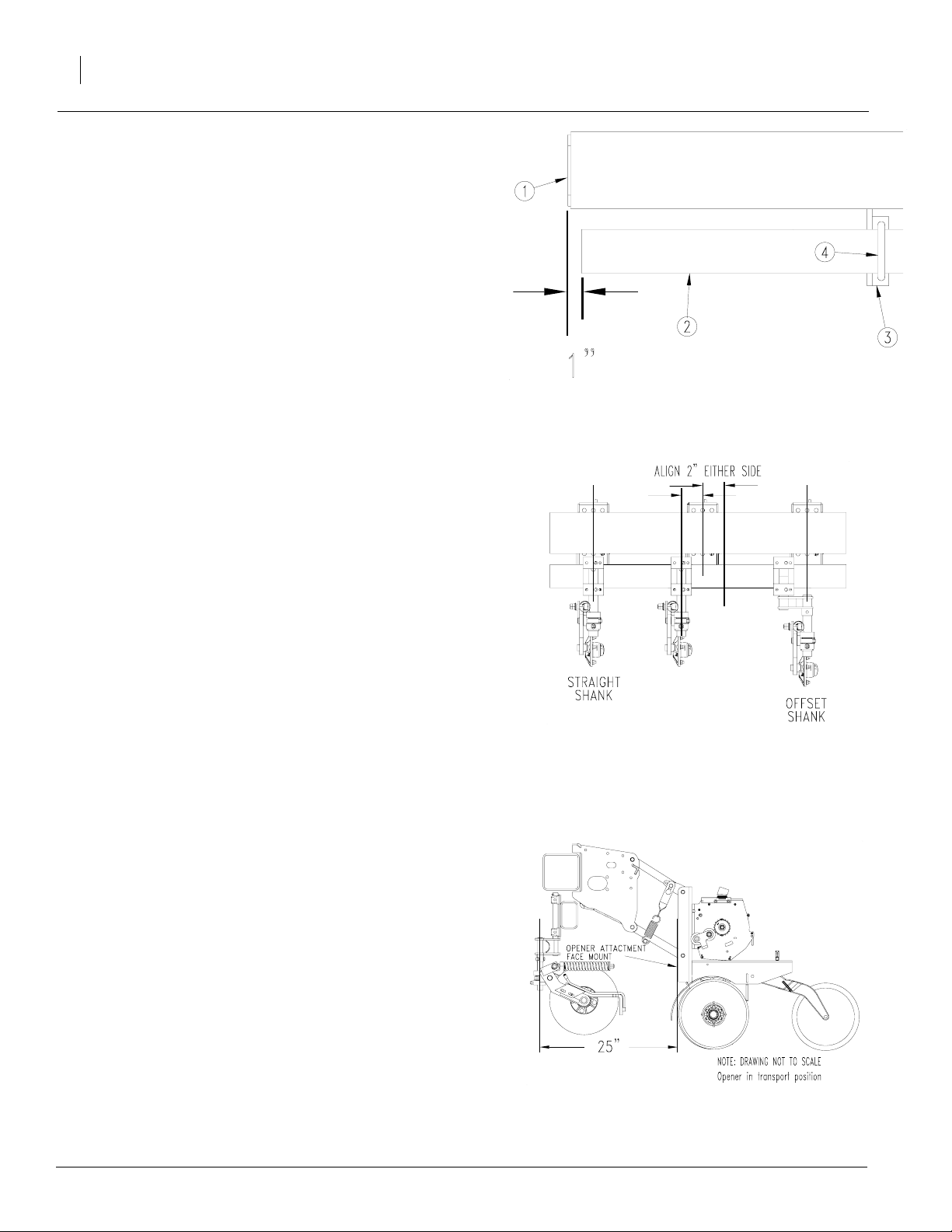
Assembly Instructions for
mounting the attachment tube
to frame on Yield-Pro® Planter
The mounting tube must be mounted as shown for
attachments to work properly.
Refer to Figure 1
Note: The longer 4”x2” tube must be mounted on
the left side of the planter.
1. The 4”x2” mounting tube (2) must be mounted so that the distance from the end of the
tube is 1” from the end of the cap of the 7”x7”
tube (1) as shown.
2. Using the attachment mounting holes (3), attach attachment tube to frame using 5/8” x 4
1/32” x 3 3/8” u-bolt (4), 5/8” lock washer, and
5/8” hex nut.
Location of Mounting Tube
Figure 1
22942
Assembly Instructions for positioning coulter with opener on
Yield-Pro® Planter
Installing Vantage I: Medium openers use 820-
343C, long openers use 204-034D, and long
openers behind gauge wheel use 820-343C.
Installing Coulters: Medium & long openers use
204-034D, unless located behind gauge wheel.
Openers located behind gauge wheel use 820343C. Opener located next to openers behind
gauge wheel will require 204-599S. If pullbar interferes with other openers near gauge wheel,
use offset 204-599S.
Refer to Figure 2
1. When using Vantage I for off-row fertilizer
placement, align coulter 2” or more to either
side of center of opener.
Refer to Figure 3
2. In order to allow enough clearance, coulter
must be 25” from front of opener to center of
coulter shank.
Figure 2
Frame Mount Coulter Set-up
22956
204-626M
Note: After installing coulters, use an assistant and check all clearances with attachments as planter is slowly folded and
unfolded.
Figure 3
Coulter Clearance
22957
1/30/2007
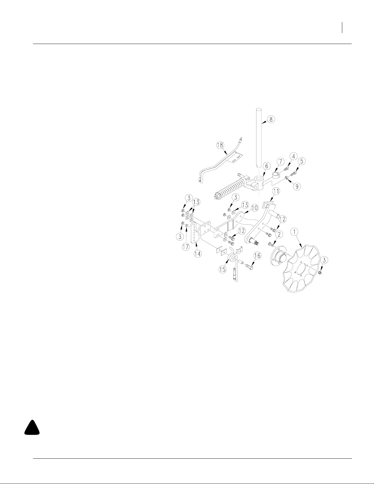
Assembly Instructions
Your Vantage I Coulter and Zone Coulter comes
to you completely assembled. Follow the instructions below for mounting.
Refer to Figure 1
1. Mount coulter blade (1) to hub using bolts (2),
and flange nuts (3). Tighten nuts. Refer to
“Torque Values Chart” above for proper
torque.
2. Lock set screws (4) & (5) in swivel coulter
casting (6) and swivel collar (7) into the drilled
dimples in vertical shaft (8). (Purchased separately.)
3. Mount clamp brackets (purchased separately) with coulter vertical shaft to tool bar. Adjust
vertically and align with furrow unit as desired, so coulter assembly is running true with
furrow unit.
4. Back off lower set screw in swivel coulter
casting (6) and lock jam nut (9) on set screw
(5).
5. Bolt the tine extension arm (10) to the coulter
swing arm using hex flange screws (12),
hardened washers (13) & hex flange nut (3).
DO NOT tighten at this time.
6. Bolt the above assembly to (14) using the hex
flanged bolts (12), hardened washers (13),
and flanged nuts (3) to the back extension
arm (14).
7. Bolt the spring tine (15) to the inside of the
back extension arm in the hole for your desired depth using bolt (16), flat washer (17)
and flange nut (3). This vertical adjustment
can be made by remounting the spring tine in
another hole in the back extension arm. Be
conscious of the horizontal movement of the
tine when adjusting the height by sliding up or
down the coulter swing arm. The desired horizontal location of the tine is between 1" and 1
1/2" behind the blade.
8. With the tine set at the desired depth and angle, tighten all hardware.
9. Some planters require extension brackets to
use the Vantage I Fertilizer Coulter. See pages 16-29 for a list of available brackets.
Operating and Assembly Instructions
Figure 1
Assembly
20110
7
!
WARNING
Great Plains denies any responsibility for damage caused to seed due to the improper application of liquid fertilizer or chemical.
It is the sole responsibility of the user of liquid fertilizer or chemical for any damage incurred.
1/30/2007
204-626M
8
Adjustments
Spring Adjustments
No down pressure spring adjustment is necessary on this unit. Initial operating force to move
coulter upwards is 428 pounds. The preload has
proved to be more than adequate for most No-Till
conditions. The torsion spring on the wheel arm
requires no adjustment. This spring applies adequate down pressure to the wheel. This controls
the soil from being pushed away from the coulter
blade, leaving the furrow as narrow as possible.
!
CAUTION
Any attempt to make coulter force greater than factory
setting, may contribute to premature failure of parts
and warranty shall be null and void.
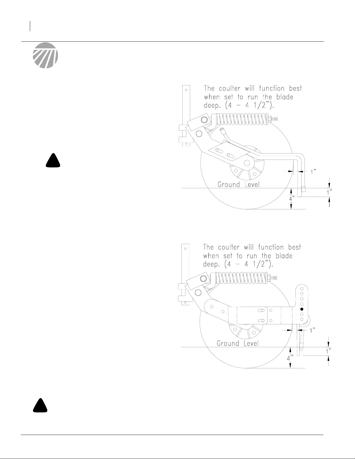
Depth Adjustments
Refer to Figure 2 and Figure 3
Set the tine applicator to run the bottom of the tine
approximately 1” below the surface of the soil.
{The tine can be set to run deeper but will cause
excessive wear and increase plugging.} Set the
tine approximately 1” behind the coulter blade in a
vertical or slightly back swept position. The main
objective is to position the tine and nozzle in the
pocket or void created by the soil as it is leaving
the back of the coulter blade while running. This
will allow the nozzle to shoot the fertilizer to the
bottom before the soil can fill back in the trench
Figure 2
Depth Adjustment
Depth Adjustment
22951
Figure 3
13248
!
WARNING
Great Plains denies any responsibility for damage caused to seed due to the improper application of liquid fertilizer or chemical.
It is the sole responsibility of the user of liquid fertilizer or chemical for any damage incurred.
204-626M
1/30/2007
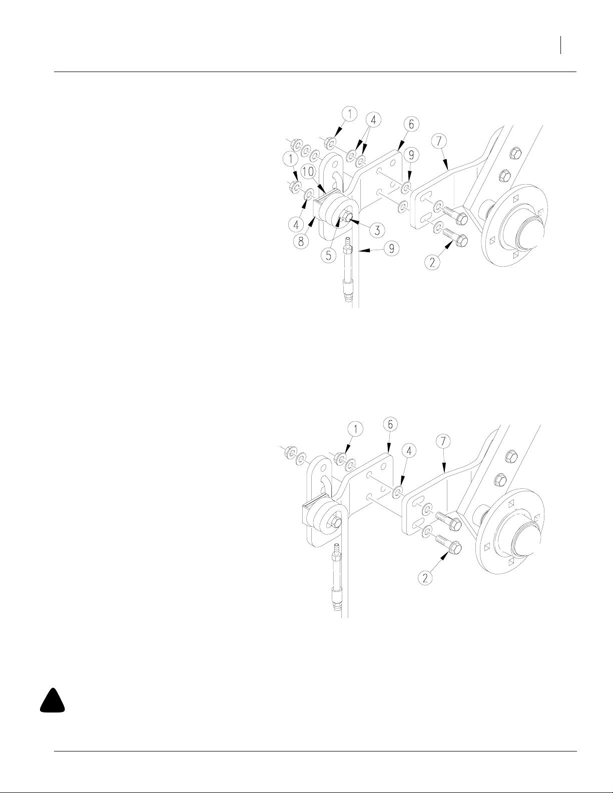
Side To Side Adjustment
Refer to Figure 4
1. Remove the 1/2" hex flange nut (1), and flat
washer (4) holding the tine (9) to the back arm
(6).
2. Center the tine behind the coulter blade by
adding or removing the 3/16" rectangular
spacer washers (10) which fit between the
back arm (6) and the fertilizer tine clip (8).
Store unused spacer washers on the opposite side of the back arm.
3. If a finer adjustment is necessary to center
the tine behind the coulter blade, place a 1/2"
flat washer (4) between the front arm (7) and
back arm (6) to shim them apart. Store unused washers on the outside of the back arm
under the
1/2" flange nuts. Once the tine is centered behind the coulter blade, make sure it is straight
with the blade and adjust the side to side rotation of the tine
Figure 4
Side to Side Adjustment
Adjustments
13252
9
Side To Side Rotation
Refer to Figure 5
1. The fertilizer tine must be straight with the
coulter blade as well as centered behind it. To
alter the side to side rotation of the tine, first
remove the hex flange nuts (1) holding the
back arm (6) to the front arm (7).
2. To rotate the bottom of the tine counterclockwise, place one 1/2" flat washer (4), between
the front arm (7) and back arm (6) on the upper hex flange bolt (2), and retighten the hex
flange nuts. Extra washers are stored behind
the hex flange nuts.
3. To rotate the bottom of the tine clockwise,
place one 1/2" flat washer (4), between the
frontarm (7) and back arm (6) on the lower
hex flange bolt (2), and retighten the hex
flange nuts.
Figure 5
Side to Side Rotation
13253
!
WARNING
Great Plains denies any responsibility for damage caused to seed due to the improper application of liquid fertilizer or chemical.
It is the sole responsibility of the user of liquid fertilizer or chemical for any damage incurred.
1/30/2007
204-626M

10
Front To Back Adjustment
Refer to Figure 5
1. Loosen the hex flange nuts (1) holding the
back arm (6) to the front arm (7).
2. Rotate the back arm assembly until the tine
reaches the desired position. It is recommended to run the tine in a vertical or slightly
swept back position.
3. Make sure the tine also has the correct front
to back distance behind the coulter and retighten the hex flange nuts.
Up & Down Adjustment
Refer to Figure 6
The bottom of the fertilizer coil tine nozzle should
be set approximately 1" to 1 1/2" below the surface of the soil when the fertilizer coulter is set for
the desired fertilizer placement depth. This allows
the nozzle to inject the fertilizer to the bottom of
the coulter trench before soil can fill back in. Running the nozzle deeper than 1 1/2" may cause
excessive wear and increase plugging problems.
1. To adjust the tine depth, remove the 1/2" hex
flange nut (1), and flat washer (4) holding the
coil tine (9) to the back arm (6).
Figure 6
Up & Down Adjustment
13252
2. Position the tine (9) to the desired height by
placing the hooked end of the coil tine in one
of the top five holes on the back plate (6).
3. Insert the 1/2" x 4 1/2" long bolt (3) through
the round spacer tube (5), the clip channel (8)
on the coil tine, the rectangular spacers (10)
and the back arm (6). Secure it with a flat
washer (4), and hex flange nut (1).
!
WARNING
Great Plains denies any responsibility for damage caused to seed due to the improper application of liquid fertilizer or chemical.
It is the sole responsibility of the user of liquid fertilizer or chemical for any damage incurred.
204-626M
1/30/2007

Maintenance and Lubrication
Maintenance
Proper servicing and adjustment is the key to the
long life of any farm implement. With careful and
systematic inspection, you can avoid costly maintenance time and repair.
1. After using your Vantage I Coulter and Zone
Coulter for several hours, check all bolts to be
sure they are tight.
2. Listed below are the items you need to lubricate
every 20 hours of operation. Use a heavy duty
multipurpose grease:
a. Grease zerk on hub.
b. Grease zerk on swivel mounting casting
Maintenance and Lubrication
11
Storage
1. Clean the Vantage I Coulter and Zone Coulter
as necessary.
2. Lubricate zerks as indicated in the following Illustrations.
3. Store the Vantage I Coulter and Zone Coulter inside if possible for longer life.
Lubrication
Lubrication Symbols
20
Lubrication is required every 20 hours of operation.
!
WARNING
Great Plains denies any responsibility for damage caused to seed due to the improper application of liquid fertilizer or chemical.
It is the sole responsibility of the user of liquid fertilizer or chemical for any damage incurred.
1/30/2007
204-626M

12
20
Hub
13245
13246
Type of Lubrication: Heavy duty multipurpose grease
20
Swivel Mounting Casting
Type of Lubrication: Heavy duty multipurpose grease
!
WARNING
Great Plains denies any responsibility for damage caused to seed due to the improper application of liquid fertilizer or chemical.
It is the sole responsibility of the user of liquid fertilizer or chemical for any damage incurred.
204-626M
1/30/2007

Application Rate Charts
Application Rate Charts
NOTE: When using a squeeze pump, use a H1/4U-SS0040 nozzle and disregard rate charts. The squeeze pump
controls the rate of application.
13
TeeJet
Capacity
Size Des-
ignation
000009 0˚ .008 .003 .005 .006 .008 .009 .011 .013 .014 .020 .025
000012 0˚ .010 .004 .006 .008 .01 .012 .015 .017 .019 .027 .033
000019 0˚ .012 .007 .009 .013 .016 .019 .023 .02 .03 .043 .062
000021 0˚ .0135 .007 .01 .015 .018 .021 .026 .03 .033 .047 .058
000050 0˚ .020 .018 .025 .035 .043 .050 .06 .07 .08 .11 .14
000067 0˚ .023 .024 .033 .05 .06 .067 .08 .09 .11 .15 .18
0001 0˚ .028 .035 .05 .07 09 .10 .12 .14 .16 .22 .27
00015 0˚ .033 .05 .07 .11 .13 .15 .18 .21 .24 .34 .41
0002 0˚ .039 .07 .10 .14 .17 .20 .25 .28 .32 .45 .55
0003 0˚ .047 .10 .15 .21 .26 .30 .37 .42 .47 .67 .82
0004 0˚ .055 .14 .20 .28 .335 .40 .49 .57 .63 .89 1.1
0005 0˚ .061 .18 .25 .35 .43 .50 .61 .71 .79 1.1 1.4
0006 0˚ .067 .21 .30 .42 .52 .60 .73 .85 .95 1.3 1.6
0008 0˚ .078 .28 .40 .56 .69 .80 .98 1.1 1.3 1.8 2.2
0010 0˚ .086 .35 .50 .71 .86 1.0 1.2 1.4 4.6 2.2 2.7
0015 0˚ .107 .53 .75 1.1 1.3 1.5 1.8 2.1 2.4 3.4 4.1
0020 0˚ .125 .71 1.0 1.4 1.7 2.0 2.5 2.8 3.2 4.5 5.5
0030 0˚ 9/64 1.1 1.5 2.1 2.6 3.0 3.7 4.2 4.7 6.7 8.2
0040 0˚ 5/32 1.4 2.0 2.8 3.5 4.0 4.9 5.7 6.3 9.0 11.0
0050 0˚ 11/64 1.8 2.5 3.5 4.3 5.0 6.1 7.1 7.9 11.2 13.7
0060 0˚ 3/16 2.1 3.0 4.2 5.2 6.0 7.3 8.5 9.5 13.4 16.4
0070 0˚ 13/64 2.5 3.5 4.9 6.1 7.0 8.6 9.9 11.1 15.7 19.2
0080 0˚ 13/64 2.8 4.0 5.6 6.9 8.0 938 113 12.6 17.9 22.0
00100 0˚ 15/64 3.5 5.0 7.1 8.6 10.0 12.2 14.1 15.8 22.0 27.0
00120 0˚ 1/4 4.2 6.0 8.5 10.4 12.0 14.7 17.0 19.0 27.0 33.0
00150 0˚ 19/64 5.3 7.5 10.6 13.0 15.0 18.4 21.0 34.0 34.0 41.0
00200 0˚ 21/64 7.1 10.0 14.1 17.3 20.0 25.0 28.0 32.0 44.0 55.0
00250 0˚ 3/8 8.8 12.5 17.7 22.0 25.0 31.0 35.0 40.0 56.0 68.0
Spray
Angle
Equiv.
Orifice
Diam.
Inches
5
psi
10
psi
20
psi
Capacity
{gallons per minute}
30
psi
40
psi
60
psi
80
psi
100
psi
200
psi
300
psi
Useful Formulas
GPM = GPA x MPH x W*
5940
5940 x GPM {Per Nozzle}
GPA =
MPH x W*
*W = Row Spacing.....in inches.
1/30/2007
11400
204-626M

14
Nozzle # Liquid
Pressure
in psi
H1/4U-SS0010 10 0.5 25 16.5 12.4 9.9 8.3 7.1 6.2 5.5 5.0
20 0.7 35 23 17.5 14 11.7 10 88 7.8 7.0
30 0.9 43 29 21 17.2 14.3 12.3 10.7 9.5 8.6
40 1.0 49 33 25 19.8 16.5 14.1 12.4 11.0 9.9
H1/4U-SS0015 10 0.8 37 25 18.6 14.9 12.4 10.6 9.3 8.3 7.4
20 1.1 53 35 26 21 17.5 15 13.1 11.4 10.5
30 1.3 64 43 32 26 21 18.4 16.1 14.3 12.9
40 1.5 74 49 37 30 25 21 18.6 16.5 14.9
H1/4U-SS0020 10 1.0 49 33 25 19.8 16.5 14.1 12.4 11.0 9.9
20 1.4 70 47 35 28 23 20 17.5 15.6 14.0
30 1.7 86 57 43 34 29 24 21 1931 17.2
40 2.0 99 65 49 40 33 28 25 22 19.8
H1/4U-SS0030 10 1.5 74 49 37 30 25 21 18.6 16.5 14.9
20 2.1 105 70 53 42 35 30 26 23 21
30 2.6 129 86 64 51 43 37 32 29 26
40 3.0 148 99 74 59 49 42 37 33 30
H1/4U-SS0040 10 2.0 99 66 49 40 33 28 25 22 19.8
20 2.8 140 93 70 56 47 40 35 31 28
30 3.5 171 114 86 69 57 49 43 38 34
40 4.0 198 132 99 79 66 57 49 44 40
H1/4U-SS0050 10 2.5 124 82 62 49 41 35 31 27 25
20 3.5 175 117 88 70 58 50 44 39 35
30 4.3 214 143 107 86 71 61 54 48 43
40 5.0 247 165 124 99 82 71 62 55 49
H1/4U-SS0060 10 3.0 148 99 74 59 49 42 37 33 30
20 4.3 210 140 105 84 70 60 53 47 42
30 5.2 257 171 129 103 86 73 64 57 51
40 6.0 297 198 148 119 99 85 74 66 59
Capacity
in gpm
Gallons Per Acre
4
mph6mph8mph10mph12mph14mph16mph18mph20mph
{The above chart is based on 30" rows}
Size Selection Of Spray Tip Or
Nozzle
Based on the chemical manufacturer’s recommendations on GPA application rates and
nozzle types, a suitable spray tip size is chosen
from the catalog tabulations. Since all the tabulations are based on spraying water, which
weighs 8.34 lbs. per USA gallon, conversion
factors must be used when spraying solutions
which are heavier or lighter than water. To arrive at the rate of solution to be sprayed multiply the conversion factor by the tabulated
GPM and GPA rates shown in this manual.
Imperial Gallon = 1.20 U.S.A. Gallons
204-626M
Weight of Solution Specific
Gravity
Conversion
Factors
7.0 lbs. per gallon .84 1.09
8.0 lbs. per gallon .96 1.02
8.34 lbs. per gallon - Water 1.00 1.00
9.0 lbs. per gallon 1.08 .96
10.0 lbs. per gallon 1.20 .91
11.0 lbs. per gallon 1.32 .87
12.0 lbs. per gallon 1.44 .83
14.0 lbs. per gallon 1.68 .77
16.0 lbs. per gallon 1.92 .72
18.0 lbs. per gallon 2.16 .68
20.0 lbs. per gallon 2.40 .65
1/30/2007

Parts
Vantage I Coulter and Zone Coulter
Parts
15
1/30/2007
13247
204-626M

16
Ref. Part No. Description
1. 204-075H COULTER SPRING ROD WLDMT
2. 204-026D SHANK 1 1/2D X 22 FERT COULT
204-025D SHANK 1 1/2D X 16 FERT COULT
204-024D SHANK 1 1/2DX12 5/8 FERT COULT
204-034D SHANK 1 1/2D X 19 FERT COULT
3. 820-132C 1 1/2 X 22 OFFSET SHANK
820-323C 16IN ROUND SHANK 4 INCH OFFSET
820-343C 1 1/2 X 19 X 6 OFFSET SHANK
204-599S YP LOW PRO 7 OFFSET SHANK ASM
4. 805-043C PIN SPIROL 3/8X2 1/2 PLAIN
5. 149-162H COULTER STOP WELDMENT
6. 801-040C SCREW SQ HD 5/8-11 X 1 CUP PT
7. 801-043C SCREW SLOTTED RD HD 3/8-16 X 1
8. 803-023C NUT HEX JAM 5/8-11 PLT
9. 805-021C PIN COTTER 1/4 X 2 PLT
10. 804-039C WASHER FLAT 1 1/4 SAE PLT
11. 204-419S SWIVEL COULTR CASTING ASSY, R
12. 800-001C GREASE ZERK STRAIGHT 1/4-28
204-420S SWIVEL COULTR CASTING ASSY, L
13. 817-029C BUSHING COULTER CASTING
14. 149-559D SPRING 2.25 O.D. X .5 COIL
15. 204-107D SPRING ROD SLEEVE 1 1/8 OD
16. 149-558D COULTER SPRING WASHER
17. 803-025C NUT HEX 3/4-10 PLT NYLOCK
18. 803-193C NUT HEX FLANGE 1/2-13 GR G PLT
19. 804-016C WASHER FLAT 1/2 SAE PLT
20. 204-241D FERTILIZER TINE SPACER
21. 830-162C AD 1/4MNPT SCH 40 X 3 304SS
22. 828-046C NOZZLE SOLIDSTRM H1/4U-SS0040
23. 802-413C HHCS 1/2-13X4 1/2 GR5
24. 204-242D FERTILIZER TINE CLIP
25. 204-360H FERTILIZER TINE WELDMENT R
26. 204-029D SPACER
204-361H FERTILIZER TINE WELDMENT L
27. 204-243D VANTAGE I FRONT FERT. ARM RH
28. 204-229D BACK ARM FERT EXT KIT
204-244D VANTAGE I FRONT FERT. ARM LH
29. 804-113C WASHER FLAT 1/2 USS HARD PLT
204-245D BACK ARM FERT EXT KIT LH
30. 803-181C NUT HEX FLANGE LOCK 3/4-10 PLT
31. 817-051C SWING ARM BUSHING
32. 204-072H COULTER SWING ARM WELDMENT
204-319H COULTER SWING ARM LH
204-595H 15" CLTR SWING ARM WELD RH
204-596H 15" CLTR SWING ARM WELD LH
33. 802-456C HFS 1/2-13X2 GR8
34. 802-214C RHSNB 1/2-13X1 1/4 GR5
35. 816-009C OIL SEAL DOUBLE LIP
36. 822-021C BEARING CONE LM-67048
37. 822-020C BEARING CUP LM-67010
38. 200-039V COULTER HUB & CUP ASSY
39. 804-055C WASHER SPINDLE - 7/8
40. 820-019C COULTER BLADE WAVY
820-082C 17 COULTER BLADE 3/4 WAVY
820-331C COULTER BLADE (FLUTED) 15" OD
820-327C COULTER BLADE (TURBO) 15" OD
41. 805-017C PIN COTTER 3/16 X 1 3/4 PLT
42. 803-029C NUT HEX SLOTTED 7/8-14 PLT
43. 200-001D HUB GREASE CAP
44. 838-482C DECAL GP PLANTING COMPONENTS
45. 204-438H VANTAGE I LH FERTILIZER ARM
204-439H VANTAGE I RH FERTILIZER ARM
204-605H V1 FERT. STD 15" ZONE CLTR RH
204-604H V1 FERT. STD 15" ZONE CLTR LH
204-626M
1/30/2007

Rectangular Tubing Clamp Kits
Part No. Width Height
204-017K
204-018K 2in X 6in
204-021K
204-022K
204-023K 5in X 7in
204-024K
204-054K
204-060K
204-064K
204-340K
204-355K
2 1/2in X 2 1/2in
4in X 4in
3in X 7in
7in X 7in
6in X 4in
2in X 4in
3in X 3in
3in X 6in
4in X 6in
Parts
17
12449
1/30/2007
204-626M

18
Ref. Part No. Description
1. 802-249C HHCS 1/2-13X4 1/2 GR5 SPTHD (204-017K Clamp Kit Only)
802-044C HHCS 1/2-13X4 GR5 (204-018K Clamp Kit Only)
802-047C HHCS 1/2-13X6 GR5 (204-021K & 204-355K Clamp Kits Only)
802-289C HHCS 1/2-13X8 GR5 (204-054K Clamp Kit Only)
802-045C HHCS 1/2-13X5 GR5 (204-022K, 204-340K, 204-064K Clamp Kits Only)
802-260C HHCS 1/2-13X7 GR5 (204-023K Clamp Kit Only)
802-269C HHCS 1/2-13X9 GR5 (204-024K Clamp Kit Only)
2. 804-015C WASHER LOCK SPRING 1/2 PLT
3. 204-037D CLAMP PLT 3 1/2 SQ BAR (204-017K Clamp Kit Only)
204-039D CLAMP PLT 6 BAR (204-018K, 204-355K, 204-340K Clamp Kits Only)
204-038D CLAMP PLT 4 BAR (204-021K & 204-054K Clamp Kits Only)
204-040D CLAMP PLT 7 BAR (204-022K, 204-023K, 204-024K Clamp Kits Only)
204-083D CLAMP PLATE 3 SQ BAR (204-064K Clamp Kit Only)
4. 204-072D CLAMP SHANK 1 1/2 DIA
5. 801-040C SCREW SQ HD 5/8-11 X 1 CUP PT
204-626M
1/30/2007

NOTE: To find your clamp kit match your diamond bar tube to the chart below
Parts
19
Part No. Bar
204-019K
204-020K
Size
3 1/2”
3”
12450
1/30/2007
204-626M

20
Ref. Part No. Part Description
1. 802-260C HHCS 1/2-13X7 GR5 (204-019K Clamp Kit Only)
802-289C HHCS 1/2-13X8 GR5 (204-020K Clamp Kit Only)
2. 804-015C WASHER LOCK SPRING 1/2 PLT
3. 204-064D CLAMP PLATE 3 DIA BAR (204-019K Clamp Kit Only)
204-041D CLAMP PLT 3 1/2 DIA BORE (204-020K Clamp Kit Only)
4. 204-077H ADAPTER PLT WLDMNT 3 DIA BAR (204-019K Clamp Kit Only)
204-079H ADAPTER PLT WLDMT 3 1/2DIA BAR (204-020K Clamp Kit Only)
5. 204-072D CLAMP SHANK 1 1/2 DIA
6. 801-040C SCREW SQ HD 5/8-11 X 1 CUP PT
204-626M
1/30/2007

Rectangular Tubing Clamps Kit
Parts
21
10188
1/30/2007
204-626M

22
1. 204-225K 3 DIA BAR CLAMP KIT
204-226K 3 1/2 DIA BAR CLAMP KIT
2. 204-212H 3DIA BAR CLAMP WELDMENT
204-213H 3 1/2 DIA BAR CLAMP WELDMENT
3. 804-022C WASHER LOCK SPRING 5/8 PLT
4. 803-021C NUT HEX 5/8-11 PLT
5. 806-085C U-BOLT 5/8-11 X3 7/8 3 CORNER
806-086C U-BOLT 5/8-11 X 4 17/32 3 CORNER
6. 204-192D 3 DIAMOND SPLIT CLAMP
204-193D 3.5 DIAMOND SPLIT CLAMP
7. 804-015C WASHER LOCK SPRING 1/2 PLT
8. 803-020C NUT HEX 1/2-13 PLT
9. 802-091C HHCS 1/2-13X1 1/2 GR5
10. 204-185D 2.5 SPLIT BAR CLAMP
204-186D 3 SPLIT BAR CLAMP
204-187D 4 SPLIT BAR CLAMP
204-188D 6 SPLIT BAR CLAMP
204-189D 7 SPLIT BAR CLAMP
11. 806-078C U-BOLT 5/8-11 X 2 17/32 X 5 Use with 204-220K.
806-079C U-BOLT 5/8-11 X 3 1/32 X 5 1/2 Use with 204-221K.
806-080C U-BOLT 5/8-11 X 4 1/32 X 6 1/2 Use with 204-222K.
806-081C U-BOLT 5/8-11 X 4 1/32 X 8 1/2 Use with 204-227K.
806-075C U-BOLT 5/8-11 X 6 1/16 X 4 1/4 Use with 204-223K.
806-083C U-BOLT 5/8-11 X 7 1/32 X 7 1/2 Use with 204-228K.
806-084C U-BOLT 5/8-11 X 7 1/32 X 9 1/2 Use with 204-224K.
806-085C U-BOLT 5/8-11 X3 7/8 3 CORNER Use with 204-225K.
806-086C U-BOLT 5/8-11 X 4 17/32 3 CORNER Use with 204-226K.
806-016C U-BOLT 5/8-11 X 6 1/32 X 5 3/8 Use with 204-341K.
806-105C U-BOLT 5/8-11 X 4 1/32 X 6 Use with 204-244K.
806-116C U-BOLT 5/8-11 X 6 1/32 X 6 1/2 Use with 204-356K.
806-131C U-BOLT 5/8-11 X 7 1/32 X 6 Use with 204-243K.
12. 204-220K 2 1/2 SQ BAR CLAMP KIT
204-221K 3 SQ BAR CLAMP KIT
204-222K 4 SQ BAR CLAMP KIT
204-223K 2W X 6H CLAMP KIT
204-224K 7 SQ BAR CLAMP KIT
204-225K 3 DIA BAR CLAMP KIT
204-226K 3 1/2 DIA BAR CLAMP KIT
204-227K 6W X 4H CLAMP KIT
204-228K 7X 5 CLAMP KIT
204-243K 3W X 7H CLAMP KIT FLAT BAR
204-244K 3W X 4H CLAMP KIT FLAT BAR
204-341K CLAMP KIT 3 W X 6 H FLAT SHANK
204-356K CLAMP KIT 4W X 6H FLAT SHANK
13. 204-190D 6 SPLIT BAR CLAMP 3EXTENSION
14. 204-191D 6 X 3 EXTENSION TUBE
15. 806-039C U-BOLT 5/8-11 X 6 1/32 X 7 3/4
16. 204-239K 3 EXTENSION CLAMP KIT FOR 2X6
204-626M
1/30/2007

Extension Brackets
Parts
23
20123
1/30/2007
204-626M

24
1. 204-423A 7X7 MAINFRAME CLAMP KIT
2. 204-279D 7X7 MAINFRAME MOUNT BACK BAR
3. 204-278D 7X7 MAINFRAME MOUNT CLAMP
4. 801-040C SCREW SQ HD 5/8-11 X 1 CUP PT
5. 802-048C HHCS 1/2-13X9 1/2 GR5
6. 804-015C WASHER LOCK SPRING 1/2 PLT
7. 204-072D CLAMP SHANK 1 1/2 DIA
8. 204-372K TELESCOPING BRACKET KIT
9. 802-105C HHCS 5/8-11X9 GR5
10. 204-033D FRONT BAR-BACK STRAP
11. 803-196C NUT HEX FLANGE 5/8-11 PLT
12. 204-381H TELESCOPING BRACKET BACK ARM
13. 802-051C HHCS 5/8-11X1 1/2 GR5
14. 204-382H TELESCOPING BRACKET FRONT ARM
15. 806-124C U-BOLT 5/8-11 X 4 1/32 X 7 3/8
204-626M
1/30/2007

Extension Brackets
Parts
25
1/30/2007
20124
204-626M

26
1. 204-364K 26 EXTENSION BRACKET
2. 204-363K 14 5/8 EXTENSION BRACKET
3. 204-358K IH 950 EXTENSION KIT 15 1/2 L
4. 204-357K IH 950 EXTENSION KIT 15 1/2 R
5. 204-112D EXTENSION BRKT 26 (2 1/2 X 7)
6. 204-123D EXT. BRKT IH800/900 3PT 14 5/8
7. 204-239D EXTENSION BRACKET IH 950 L
8. 204-240D EXTENSION BRACKET IH 950 R
9. 204-033D FRONT BAR-BACK STRAP
10. 802-105C HHCS 5/8-11X9 GR5
11. 804-022C WASHER LOCK SPRING 5/8 PLT
12. 803-021C NUT HEX 5/8-11 PLT
13. 803-020C NUT HEX 1/2-13 PLT
14. 804-015C WASHER LOCK SPRING 1/2 PLT
15. 806-010C U-BOLT 1/2-13 X 2 1/2 X 3 1/2
204-626M
1/30/2007

Extension Brackets
Parts
27
1/30/2007
20125
204-626M

28
1. 204-351K COULTER EXT. KIT LEFT SHORT
2. 204-352K COULTER EXT. KIT RIGHT SHORT
3. 204-353K COULTER EXT. KIT LEFT LONG
4. 204-354K COULTER EXT. KIT RIGHT LONG
5. 890-543C COULTER EXTENSION LEFT
6. 890-542C COULTER EXTENSION RIGHT
7. 890-547C COULTER EXTENSION LEFT LONG
8. 890-548C COULTER EXTENSION RIGHT LONG
9. 204-236D COULTER EXT. TOP SUPPORT
10. 802-164C HHCS 3/4-10X9 GR5
11. 804-023C WASHER LOCK SPRING 3/4 PLT
12. 803-027C NUT HEX 3/4-10 PLT
204-626M
1/30/2007

Extension Brackets
Parts
29
20127
1/30/2007
204-626M

30
1. 204-365K 31 1/2 EXTENSION BRACKET
2. 204-430S 9 1/2 EXTENSION BUNDLE
3. 204-038K EXT. BRKT X 10
4. 204-039K EXT. BRKT 3 DIA. BAR
5. 204-031K FRONT BAR REINFORCEMENT BRKT
6. 204-082H EXTENSION BRACKET 31 9/16 JD
7. 204-023D SPACER PLT 7 TO 2 1/2 SQ 9 1/2
8. 204-044H 10 EXT. BRKT
9. 204-058H EXT. BRKT. DRY FERT 3 DIA
10. 204-029H FRONT BAR BRKT 18
11. 204-033D FRONT BAR-BACK STRAP
12. 802-105C HHCS 5/8-11X9 GR5
13. 802-260C HHCS 1/2-13X7 GR5
14. 802-053C HHCS 5/8-11X1 3/4 GR5
15. 806-010C U-BOLT 1/2-13 X 2 1/2 X 3 1/2
16. 806-055C U-BOLT 3/4-10 X 7 1/32 X 6 1/2
17. 806-050C U-BOLT 3/4-10 X 7 X 8 1/2
18. 804-015C WASHER LOCK SPRING 1/2 PLT
19. 804-022C WASHER LOCK SPRING 5/8 PLT
20. 804-023C WASHER LOCK SPRING 3/4 PLT
21. 803-020C NUT HEX 1/2-13 PLT
22. 803-021C NUT HEX 5/8-11 PLT
23. 803-027C NUT HEX 3/4-10 PLT
24. 804-017C WASHER FLAT 1/2 USS PLT
204-626M
1/30/2007

Parts
31
1/30/2007
20120
204-626M

32
Appendix
Torque Values Chart
Bolt Head Identification
Bolt Head Identification
Bolt Size
(Inches)
1
in-tpi
1/4" - 20 7.4 5.6 11 8 16 12 M 5 X 0.8 4 3 6 5 9 7
1/4" - 28 8.5 6 13 10 18 14 M 6 X 1 7 5 11 8 15 11
5/16 - 18 15 11 24 17 33 25 M 8 X 1.25 17 12 26 19 36 27
5/16" - 24 17 13 26 19 37 27 M 8 X 1 18 13 28 21 39 29
3/8" - 16 27 20 42 31 59 44 M10 X 1.5 33 24 52 39 72 53
3/8" - 24 31 22 47 35 67 49 M10 X 0.75 39 29 61 45 85 62
7/16" - 14 43 32 67 49 95 70 M12 X 1.75 58 42 91 67 125 93
7/16" - 20 49 36 75 55 105 78 M12 X 1.5 60 44 95 70 130 97
1/2" - 13 66 49 105 76 145 105 M12 X 1 90 66 105 77 145 105
1/2" - 20 75 55 115 85 165 120 M14 X 2 92 68 145 105 200 150
9/16" - 12 95 70 150 110 210 155 M14 X 1.5 99 73 155 115 215 160
9/16" - 18 105 79 165 120 235 170 M16 X 2 145 105 225 165 315 230
5/8" - 11 130 97 205 150 285 210 M16 X 1.5 155 115 240 180 335 245
5/8" - 18 150 110 230 170 325 240 M18 X 2.5 195 145 310 230 405 300
3/4" - 10 235 170 360 265 510 375 M18 X 1.5 220 165 350 260 485 355
3/4" - 16 260 190 405 295 570 420 M20 X 2.5 280 205 440 325 610 450
7/8" - 9 225 165 585 430 820 605 M20 X 1.5 310 230 650 480 900 665
7/8" - 14 250 185 640 475 905 670 M24 X 3 480 355 760 560 1050 780
1" - 8 340 250 875 645 1230 910 M24 X 2 525 390 830 610 1150 845
1" - 12 370 275 955 705 1350 995 M30 X 3.5 960 705 1510 1120 2100 1550
1-1/8" - 7 480 355 1080 795 1750 1290 M30 X 2 1060 785 1680 1240 2320 1710
1 1/8" - 12 540 395 1210 890 1960 1440 M36 X 3.5 1730 1270 2650 1950 3660 2700
1 1/4" - 7 680 500 1520 1120 2460 1820 M36 X 2 1880 1380 2960 2190 4100 3220
1 1/4" - 12 750 555 1680 1240 2730 2010
1 3/8" - 6 890 655 1990 1470 3230 2380
1 3/8" - 12 1010 745 2270 1670 3680 2710
1 1/2" - 6 1180 870 2640 1950 4290 3160
1 1/2" - 12 1330 980 2970 2190 4820 3560
Grade 2 Grade 5
N · m2ft-lb3N · m ft-lb N · m ft-lb mm x pitch4N · m ft-lb N · m ft-lb N · m ft-lb
Torque tolerance + 0%, -15% of torquing values. Unless otherwise specified use torque values listed above.
Grade 8
Bolt Size
(Metric)
1
in-tpi = nominal thread diameter in inches-threads per inch
4
mm x pitch = nominal thread diameter in millimeters x thread pitch
5.8 8.8 10.9
Class 5.8 Class 8.8 Class 10.9
2
N· m = newton-meters
3
ft-lb= foot pounds
204-626M
1/30/2007

Warranty
Great Plains Manufacturing, Incorporated warrants to the original purchaser that this seeding equipment will be free from defects in material
and workmanship for a period of one year from the date of original purchase when used as intended and under normal service and conditions
for personal use; 90 days for commercial or rental purposes. This Warranty is limited to the replacement of any defective part by Great Plains
Manufacturing, Incorporated and the installation by the dealer of any
such replacement part. Great Plains reserves the right to inspect any
equipment or part which are claimed to have been defective in material
or workmanship.
This Warranty does not apply to any part or product which in Great
Plains’ judgement shall have been misused or damaged by accident or
lack of normal maintenance or care, or which has been repaired or altered in a way which adversely affects its performance or reliability, or
which has been used for a purpose for which the product is not designed. This Warranty shall not apply if the product is towed at a speed
in excess of 20 miles per hour.
Claims under this Warranty must be made to the dealer which originally
sold the product and all warranty adjustments must by made through
such dealer. Great Plains reserves the right to make changes in materials or design of the product at any time without notice.
This Warranty shall not be interpreted to render Great Plains liable for
damages of any kind, direct, consequential, or contingent, to property.
Furthermore, Great Plains shall not be liable for damages resulting from
any cause beyond its reasonable control. This Warranty does not extend to loss of crops, losses caused by harvest delays or any expense
or loss for labor, supplies, rental machinery or for any other reason.
No other warranty of any kind whatsoever, express or implied, is
made with respect to this sale; and all implied warranties of merchantability and fitness for a particular purpose which exceed
the obligations set forth in this written warranty are hereby disclaimed and excluded from this sale.
This Warranty is not valid unless registered with Great Plains Manufacturing, Incorporated within 10 days from the date of original purchase.
Appendix
33
1/30/2007
204-626M

Great Plains Manufacturing, Inc.
Corporate Office: PO. Box 5060
Salina, Kansas 67402-5060 USA
 Loading...