

Great Plains Mfg., Inc.
YP Drive Shaft Update Kit
Yield-Pro Planters
Used with:
• Pre-2007 12- and 16-row Yield-Pro Planters
General Information
Installation Instructions 1
These instructions explain how to install the YP Drive
Shaft Update Kit.
These instructions apply to:
401-461K YP Drive Shaft Update Kit
Before You Start
Each kit converts an entire planter. Inventory the contents per the “Parts List” on page 3.
Raise and fold the planter. Install lift cylinder locks
Installation
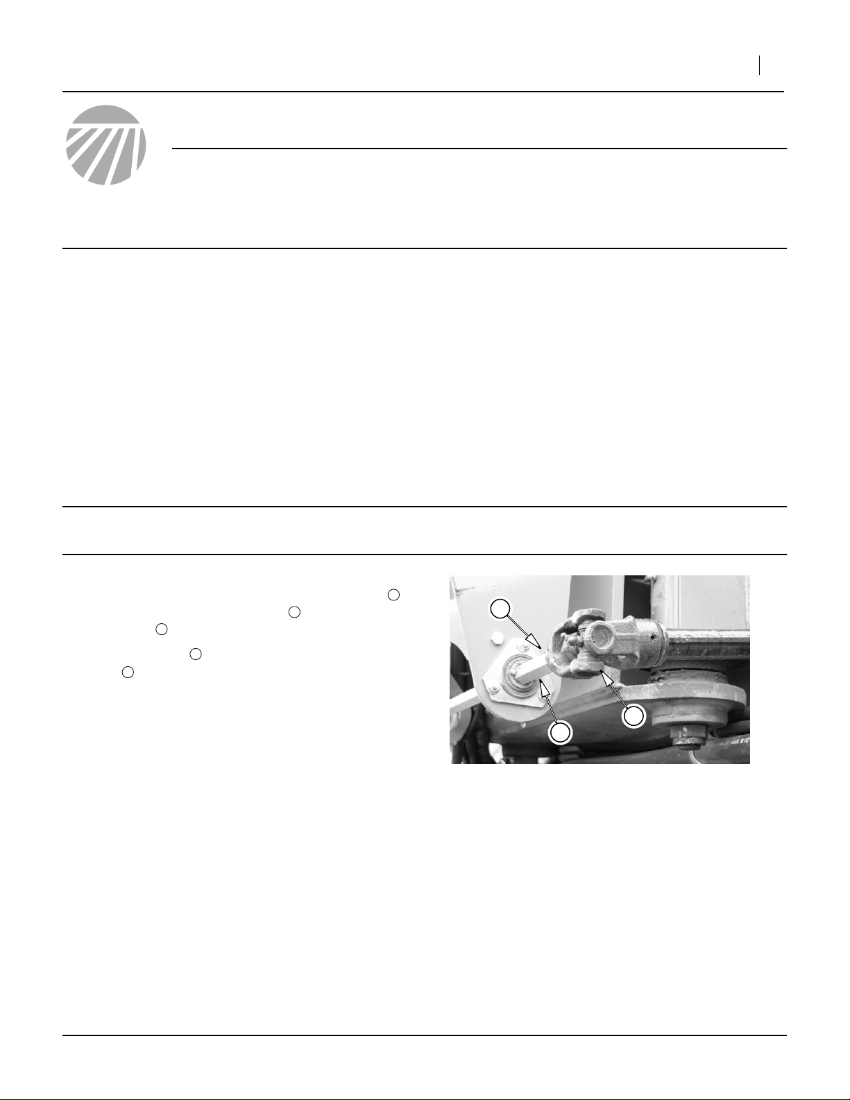
Refer to Figure 1,.
1. On the right side drive shaft, drive out the roll pin
that attaches the inboard U-joint to the center
drive shaft . The pin is not reused.
2. Slide the U-joint off the right end of the center
shaft .
3
2
3
2
Note: Although this update can be performed with the
planter unfolded, these instructions assume a
folded planter.
If necessary, move the implement to a dry well-lighted
location suitable for disassembly.
Park and secure the implement. Secure the tractor if left
connected. Disconnect any hydraulic and electrical
power to the implement.
“Left” and “Right” are facing in the direction of machine
travel.
Have the following tools at hand:
• Basic hand tools (including a1⁄4in roll-pin punch)
1
1
3
2
Figure 1
Inboard Right U-Joint
©Copyright 2006 Printed 12/21/2006 401-464M
25145
2 YP Drive Shaft Update Kit
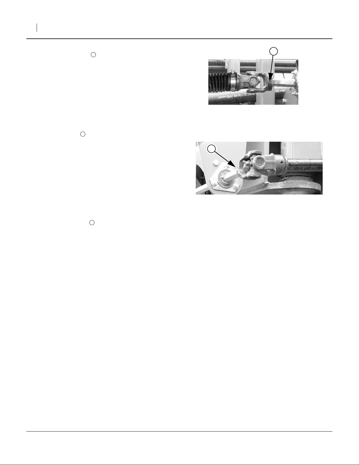
Refer to Figure 2
3. Drive out the roll pin at the outboard end of the
right drive shaft. The pin is not reused.
4. Remove the old drive shaft from the planter. It is not
re-used.
5. Repeat steps 1 through 4 for the left side drive
shaft.
Refer to Figure 2
6. Taking note of pin hole alignment, slide the outboard (bellows end) U-Joint of a new drive shaft
onto the wing drive shaft extension.
4
4
Figure 2
Outboard Right U-Joint
Great Plains Mfg., Inc.
➂
25144
7. Insert a new pin .
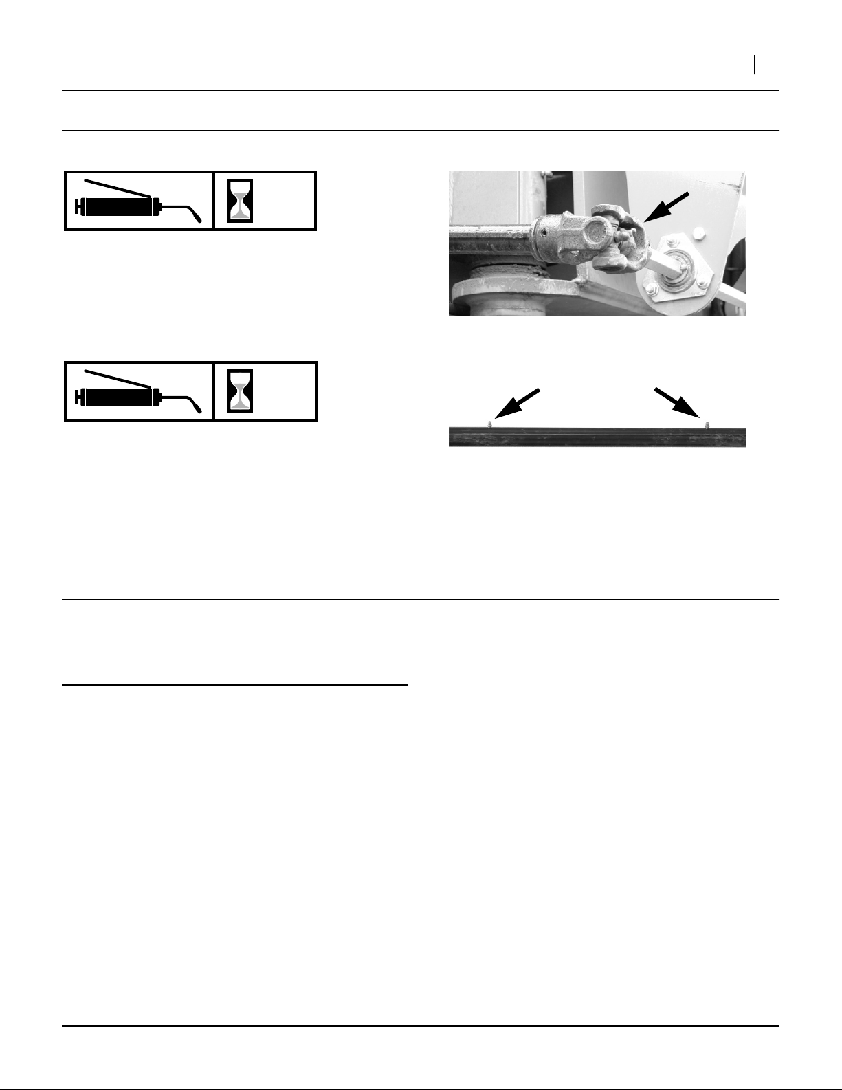
Refer to Figure 3
8. Extend the new drive shaft until the inboard U-joint
is near the center drive shaft.
9. Rotate the new drive shaft until the new inboard Ujoint can be rotated 90 degrees to align with the
center drive shaft.
10. Rotate the center drive shaft until the roll pin holes
align. This usually requires some effort. A7⁄8in
open-end wrench may be used for leverage.
11. Slide the U-joint over the center drive shaft and
insert a new roll pin .
12. Repeat steps 6 through 11 for the other side.
13. If the inner shafts were not pre-greased, attach a
grease gun to each shaft zerk, and pump in a small
amount of grease. Do not fill the inner space with the
shaft extended, or almost all of that grease will be
forced out when the planter is unfolded.
14. Perform normal lubrication at the U-joint zerks.
4
5
5
➂
Figure 3
Insert Inboard Pin
25145
401-464M 12/21/2006
Great Plains Mfg., Inc.
Maintenance
Lubrication
Drive Shaft U-Joints
Two zerks, one each end.
Type of Lubrication: Grease
Quantity = Until grease emerges.
Installation Instructions 3
25145
50
8
Drive Shaft Tubes
Two zerks.
Type of Lubrication: Grease
Quantity = 6 pumps.
Note: This lubrication must be performed with the planter
unfolded.
Parts List
401-461K YP Drive Shaft Update Kit
Your kit includes:
Qty. Part No. Part Description
1 401-464M This manual
2 401-481S DRIVE SHAFT ASY
4 805-146C PIN ROLL 1/4 X 2 LG PL
25152
Great Plains Manufacturing, Inc.
Corporate Office: PO Box 5060
Salina, KS 67402-5060 USA
12/21/2006 401-464M
 Loading...