

Great Plains YP2425F-2470 Operator Manual
Table of Contents Index
Operator Manual
YP2425 and YP2425F
60 Foot Yield-Pro® Planter
Manufacturing, Inc.
www.greatplainsmfg.com
Read the operator manual entirely. When you see this symbol, the subsequent
instructions and warnings are serious - follow without exception. Your life and
!
the lives of others depend on it!
Illustrations may show optional equipment not supplied with standard unit.
25205
ORIGINAL INSTRUCTIONS
© Copyright 2012 Printed 2014-07-14 401-406M
Table of Contents Index
EN
EN

Table of Contents Index
Table of Contents Index

Great Plains Manufacturing, Inc. Cover Index iii
Table of Contents
Important Safety Information ...................................... 1
Safety Decals .................................................................6
Introduction ................................................................12
Document Family......................................................12
Description of Unit ........................................................ 12
Intended Usage ........................................................12
Models Covered ...........................................................12
Using This Manual........................................................12
Definitions................................................................. 12
Owner Assistance ........................................................13
Product Support .......................................................13
Preparation and Setup ............................................... 14
Post-Delivery/Seasonal Setup......................................14
Pre-Planting Setup .......................................................14
Hitching Tractor to Planter............................................15
Hitching with 3-Point................................................. 15
Hitching with Hydraulic Tongue (Option)..................16
Raising/Lowering Tongue......................................... 16
Local Float on Hydraulic Tongue.............................. 16
Hydraulic Hose Hookup................................................17
Protecting Fan Hydraulic Motor Seals......................18
Electrical Hookup .........................................................19
Store Main Parking Stand.....................................19
Storing 3-Point Parking Stands ............................20
Tank Cart Hitching.................................................... 20
Fertilizer Connection Types..................................20
Making Fertilizer Connections ..................................21
Heights and Leveling....................................................21
Set Tongue Height ...................................................21
Checking Planter Leveling Side to Side ...................22
Center Section Level Check.....................................22
Wing Leveling...............................................................23
Wing Leveling, Inboard End .....................................23
Wing Leveling, Outboard End...................................23
Lock Up Fertilizer Drive ................................................ 24
Operating Instructions...............................................25
Pre-Start Checklist .......................................................25
Unfolding The YP24 .....................................................26
Raising/Lowering Planter .............................................28
Local Float on Hydraulic Tongue..........................28
Raising Planter .........................................................29
Lowering Planter ......................................................29
Folding the YP24..........................................................30
Re-phasing Fold System.......................................... 32
Lift Cylinder Lock-Up................................................ 32
Re-Phasing Lift System............................................ 32
Transporting the Planter .............................................. 33
Transport Checklist .................................................. 34
Steering.................................................................... 34
Field Set-Up Checklist ................................................. 35
Field Operation ............................................................ 37
Marker Unfolding.......................................................... 38
Marker Unfold (one side).......................................... 39
Row Marker Operation ............................................. 39
Folding the Markers ................................................. 39
Unusual Marker Operations ..................................... 39
Both Sides Unfolded ............................................ 39
Monitor Operation ........................................................ 39
Planting ........................................................................ 40
Electric Clutch Operation ............................................. 41
Clutch Switch Coverage........................................... 41
Electric Clutch Lock-Up............................................ 41
Swath Command™ Clutch Operation.......................... 42
Y-Tubes ....................................................................... 42
Airbox Operation .......................................................... 43
Fan Operation .......................................................... 43
82 bu. Hopper Operation ............................................. 44
Adding Seed to 82bu Hopper................................... 44
Changing the Seed Box or 82 bu. Hopper ................... 45
Checking Planting Rate ............................................... 46
Auxiliary Hydraulics...................................................... 47
Operating Auxiliary Hydraulics ................................. 47
Trailer Operations ........................................................ 48
Short-Term Parking...................................................... 49
Long-Term Storage...................................................... 50
Adjustments ............................................................... 51
Gauge/Transport Wheel
Adjustments ......................................................... 52
Marker Adjustments ..................................................... 52
Marker Disk Adjustment ........................................... 53
Marker Extension ..................................................... 53
Marker Gauge Wheel Adjustment ............................ 54
Marker Shear Bolt Replacement .............................. 54
Marker Chain Length Adjustment............................. 54
Dual Marker Speed Adjustment ............................... 55
Height Switch Adjustment ............................................ 56
© Copyright 2006, 2007, 2008, 2009, 2010, 2011, 2012, 2014. All rights Reserved
Great Plains Manufacturing, Inc. provides this publication “as is” without warranty of any kind, either expressed or implied. While every precaution has been
taken in the preparation of this manual, Great Plains Manufacturing, Inc. assumes no responsibility for errors or omissions. Neither is any liability assumed for
damages resulting from the use of the information contained herein. Great Plains Manufacturing, Inc. reserves the right to revise and improve its products as
it sees fit. This publication describes the state of this product at the time of its publication, and may not reflect the product in the future.
2014-07-14 Cover Index 401-406M
Trademarks of Great Plains Manufacturing, Inc. include: Singulator Plus, Swath Command, Terra-Tine.
Registered Trademarks of Great Plains Manufacturing, Inc. include:
Air-Pro, Clear-Shot, Discovator, Great Plains, Land Pride, MeterCone, Nutri-Pro, Seed-Lok, Solid Stand,
Terra-Guard, Turbo-Chisel, Turbo-Chopper, Turbo Max, Turbo-Till, Ultra-Till, Ver ti-Till, Whirlfilter, Yield-Pro.
Brand and Product Names that appear and are owned by others are trademarks of their respective owners.
Printed in the United States of America

iv YP24 Table of Contents Index Great Plains Manufacturing, Inc.
Height Switch Adjustment ............................................ 57
Fan Adjustments .......................................................... 58
Liquid Fertilizer Setup .................................................. 59
John Blue Ground Drive Pump ................................ 60
Hypro Ground Drive Pump....................................... 60
Liquid Fertilizer Strainer(s) ................................... 61
Fertilizer Relief Valve ............................................... 61
Fertilizer Orifice Plates............................................. 62
Frame-Mounted Row Accessories............................... 63
Terra-Tine™ Adjustments........................................ 63
Using Terra-Tines with Coulters........................... 63
Frame-Mounted Coulter Adjustments ...................... 64
On-Row ................................................................ 64
Between Row (or Off-Row at least 2 inches) ....... 64
Vantage I Fertilizer Adjustments .............................. 64
25 Series Row Unit Adjustments ................................. 65
Row Unit Down Pressure......................................... 66
Adjusting Down-Force.......................................... 66
Row Unit Lock-Up .................................................... 68
Unit-Mount Cleaner Adjustments ......................... 69
Coulter Adjustments................................................. 70
Coulter Depth Adjustment .................................... 70
Coulter Row Alignment ........................................ 71
Row-Unit Opener Disk Adjustments......................... 72
Setting Planting Depth ......................................... 72
Opener Disc Contact Region ............................... 72
Adjusting Disc Contact ......................................... 72
Side Gauge Wheel Adjustment................................ 73
Adjusting Gauge Wheel Scrapers ........................ 74
Seed Meter Setup and Adjustment .......................... 75
Meter Removal..................................................... 75
Singulator Plus™ Meter Wheel Replacement...... 77
Meter Installation.................................................. 78
Finger Meter Adjustments .................................... 78
Finger Meter Brush Adjustment ........................... 79
Sprocket Indexing (Stagger) ................................ 80
Finger Meter Inserts ............................................. 80
Seed Firmer Adjustments..................................... 81
Keeton Seed Firmer Adjustment .......................... 81
Seed-Lok® Seed Firmer Lock-Up ........................ 81
Seed-Lok® Seed Firmer Lock-Up (older style)..... 82
Press Wheel Adjustment.......................................... 83
Press Wheel Down Pressure ............................... 83
Press Wheel Stagger ........................................... 83
Press Wheel Centering ........................................ 84
Troubleshooting......................................................... 85
General Troubleshooting ............................................. 85
Airbox Troubleshooting ................................................ 88
Maintenance and Lubrication ................................... 89
Maintenance ................................................................ 89
Bleeding Hydraulics ..................................................... 90
Bleeding Lift Hydraulics ........................................... 90
Bleeding Fold Cylinder Hydraulics ........................... 90
Fold Cylinder Bleeding..........................................91
Bleeding Marker Hydraulics......................................91
Marker Cylinder Bleeding .....................................91
Wing Alignment.........................................................92
Cleaning Out Meters.....................................................93
Seed Tube Clean-Out...............................................93
Cleaning Out Air System ..............................................94
Meter Drive Chain.........................................................94
Finger Set Installation Instructions ...............................95
Installation Steps ......................................................95
Annual Maintenance .................................................95
Precautions...........................................................95
25 Series Spreaders and Scrapers ..............................96
25 Series Row-Unit Side Wheels..............................96
Chain Maintenance.......................................................97
Seed Flap Replacement (s/n A1067Q+).......................98
Seed Flap Replacement (s/n A1066Q-) .......................98
Liquid Fertilizer System Maintenance...........................99
Liquid Fertilizer Strainer............................................99
Lubrication and Scheduled Maintenance ...................100
Seed Lubricants......................................................108
Options ......................................................................109
Appendix A - Reference Information ......................121
Specifications and Capacities.....................................121
North American Models ..........................................121
Metric Model Specifications ....................................122
Tire Inflation Chart ......................................................122
Torque Values Chart ..................................................123
Hydraulic Diagrams ....................................................124
Chain Routing.............................................................133
Appendix B - Initial Setup ........................................140
Seed Monitor Console Installation..............................140
Radar Calibration........................................................140
Appendix C - Option Installation.............................141
Appendix R - Row-Pro™ ..........................................143
Preparation and Setup................................................143
Row-Pro™ Setup (Option)......................................143
Row-Pro™ Operating Instructions..............................144
Row-Pro™ Components.............................................145
Load Cell, DPLCM and Valves ...............................145
Row-Pro™ Electrical System..................................145
Row-Pro™ Air Compressor System .......................146
Row-Pro™ Adjustments .............................................147
Row-Pro™ Air Pressure Gauge..............................148
Row-Pro™: Setting the Springs..............................148
Row-Pro™ Troubleshooting .......................................149
Row-Pro™ Maintenance ............................................149
Warranty .....................................................................150
Index ..........................................................................151
401-406M Table of Contents Index 2014-07-14
Great Plains Manufacturing, Inc. Table of Contents Index 1
Important Safety Information
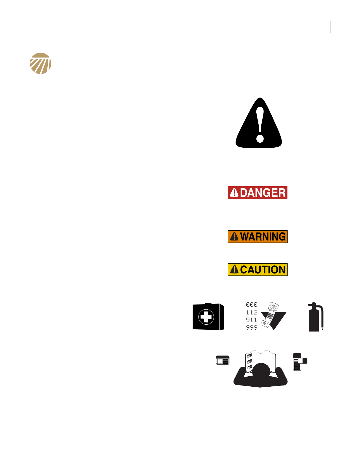
Look for Safety Symbol
The SAFETY ALERT SYMBOL indicates there is a
potential hazard to personal safety involved and extra
safety precaution must be taken. When you see this
symbol, be alert and carefully read the message that
follows it. In addition to design and configuration of
equipment, hazard control and accident prevention are
dependent upon the awareness, concern, prudence and
proper training of personnel involved in the operation,
transport, maintenance and storage of equipment.
Be Aware of Signal Words
Signal words designate a degree or level of hazard
seriousness.
DANGER indicates an imminently hazardous situation
which, if not avoided, will result in death or serious injury.
This signal word is limited to the most extreme situations,
typically for machine components that, for functional
purposes, cannot be guarded.
WARNING indicates a potentially hazardous situation
which, if not avoided, could result in death or serious
injury, and includes hazards that are exposed when
guards are removed. It may also be used to alert against
unsafe practices.
CAUTION indicates a potentially hazardous situation
which, if not avoided, may result in minor or moderate
injury. It may also be used to alert against unsafe
practices.
Prepare for Emergencies
▲ Be prepared if a fire starts
▲ Keep a first aid kit and fire extinguisher handy.
▲ Keep emergency numbers for doctor, ambulance, hospital
and fire department near phone.
Be Familiar with Safety Decals
▲ Read and understand “Safety Decals” on page 6,
thoroughly.
▲ Read all instructions noted on the decals.
▲ Keep decals clean. Replace damaged, faded and illegible
decals.
2014-07-14 Table of Contents Index 401-406M

2 YP2425 & YP2425F Table of Contents Index Great Plains Manufacturing, Inc.
Wear Protective Equipment
▲ Wear protective clothing and equipment.
▲ Wear clothing and equipment appropriate for the job. Avoid
loose-fitting clothing.
▲ Because prolonged exposure to loud noise can cause
hearing impairment or hearing loss, wear suitable hearing
protection such as earmuffs or earplugs.
▲ Because operating equipment safely requires your full
attention, avoid wearing entertainment headphones while
operating machinery.
Handle Chemicals Properly
Agricultural chemicals can be dangerous. Improper use
can seriously injure persons, animals, plants, soil and
property.
▲ Read and follow chemical manufacturer’s instructions.
▲ Wear protective clothing.
▲ Handle all chemicals with care.
▲ Avoid inhaling smoke from any type of chemical fire.
▲ Store or dispose of unused chemicals as specified by
chemical manufacturer.
Avoid High Pressure Fluids
Escaping fluid under pressure can penetrate the skin,
causing serious injury.
▲ Avoid the hazard by relieving pressure before disconnecting
hydraulic lines.
▲ Use a piece of paper or cardboard, NOT BODY PARTS, to
check for suspected leaks.
▲ Wear protective gloves and safety glasses or goggles when
working with hydraulic systems.
▲ If an accident occurs, seek immediate medical assistance
from a physician familiar with this type of injury.
401-406M Table of Contents Index 2014-07-14
Great Plains Manufacturing, Inc. Table of Contents Index Important Safety Information 3
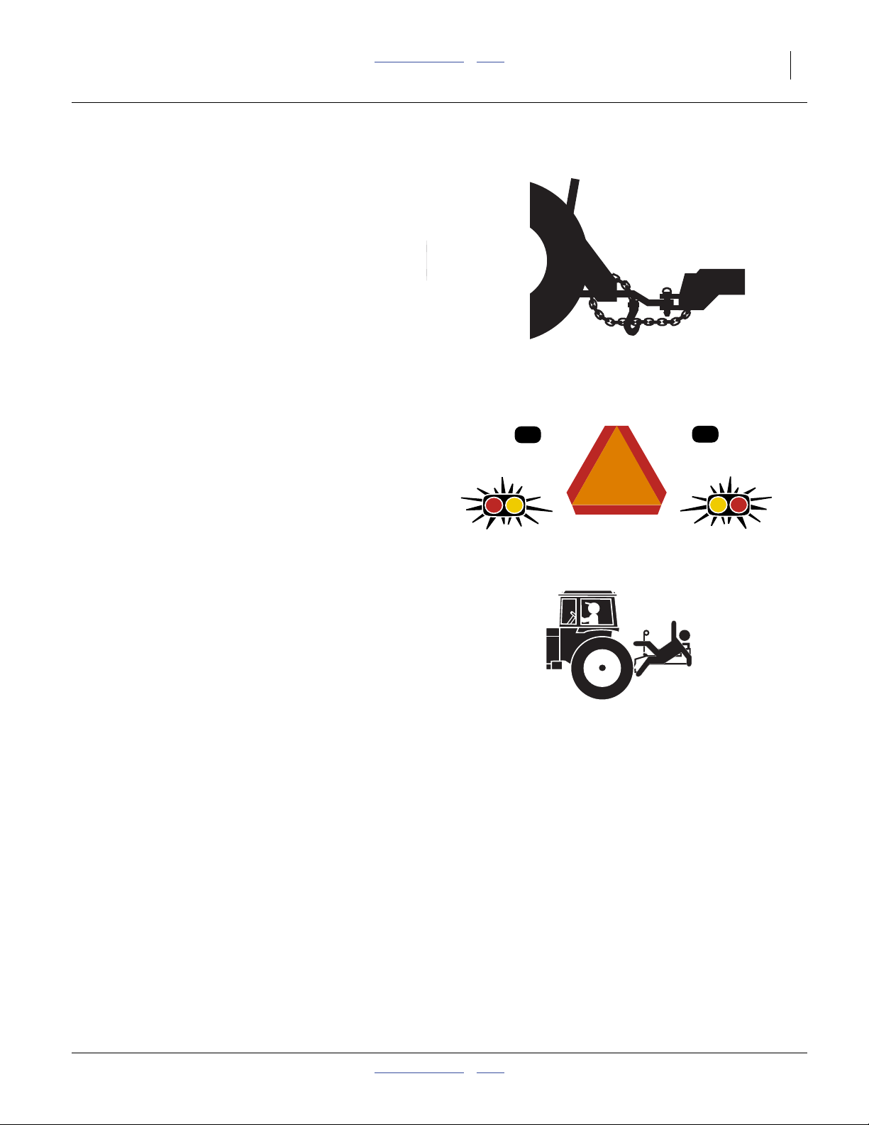
Use A Safety Chain
(Optional hydraulic hitch only. 3-Point has no chain.)
▲ Use a safety chain to help control drawn machinery should
it separate from tractor draw-bar.
▲ Use a chain with a strength rating equal to or greater than
the gross weight of towed machinery.
▲ Attach chain to tractor draw-bar support or other specified
anchor location. Allow only enough slack in chain to permit
turning.
▲ Replace chain if any links or end fittings are broken,
stretched or damaged.
▲ Do not use safety chain for towing.
Use Safety Lights and Devices
Slow-moving tractors and towed implements can create
a hazard when driven on public roads. They are difficult
to see, especially at night.
▲ Use flashing warning lights and turn signals whenever
driving on public roads.
▲ Use lights and devices provided with implement
Keep Riders Off Machinery
Riders obstruct the operator’s view. Riders could be
struck by foreign objects or thrown from the machine.
▲ Never allow children to operate equipment.
▲ Keep all bystanders away from machine during operation.
2014-07-14 Table of Contents Index 401-406M
4 YP2425 & YP2425F Table of Contents Index Great Plains Manufacturing, Inc.
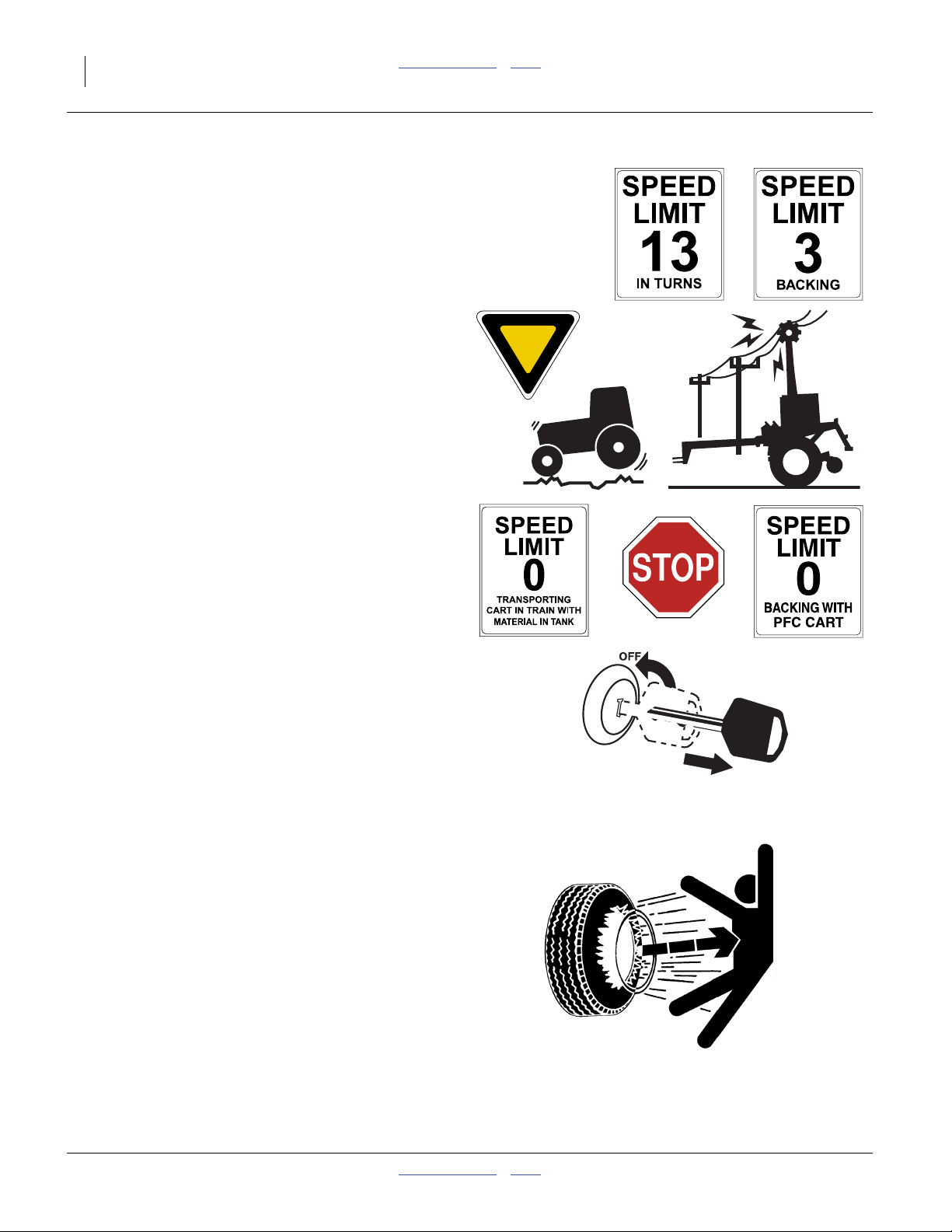
Transport Machinery Safely
Maximum transport speed for implement is 20 mph (32
kph), 13 mph (22 kph) in turns. Some rough terrains
require a slower speed. Sudden braking can cause a
towed load to swerve and upset.
▲ Do not exceed 20 mph. Never travel at a speed which does
not allow adequate control of steering and stopping. Reduce
speed if towed load is not equipped with brakes.
▲ Comply with state and local laws.
▲ Do not tow an implement that, when fully loaded, weighs
more than 1.5 times the weight of towing vehicle.
▲ Carry reflectors or flags to mark planter in case of
breakdown on the road.
▲ Keep clear of overhead power lines and other obstructions
when transporting. Refer to transport dimensions under
“Specifications and Capacities” on page 121.
▲ Do not fold or unfold the planter while the tractor is moving
Shutdown and Storage
▲ Lower planter, put tractor in park, turn off engine, and
remove the key.
▲ Secure planter using blocks and supports provided.
▲ Detach and store planter in an area where children
normally do not play.
Tire Safety
Tire changing can be dangerous and should be
performed by trained personnel using correct tools and
equipment.
▲ When inflating tires, use a clip-on chuck and extension hose
long enough for you to stand to one side–not in front of or
over tire assembly. Use a safety cage if available.
▲ When removing and installing wheels, use wheel-handling
equipment adequate for weight involved.
401-406M Table of Contents Index 2014-07-14

Great Plains Manufacturing, Inc. Table of Contents Index Important Safety Information 5
Practice Safe Maintenance
▲ Understand procedure before doing work. Use proper tools
and equipment. Refer to this manual for additional
information.
▲ Work in a clean, dry area.
▲ Lower the planter, put tractor in park, turn off engine, and
remove key before performing maintenance.
▲ Make sure all moving parts have stopped and all system
pressure is relieved.
▲ Allow planter to cool completely.
▲ Disconnect battery ground cable (-) before servicing or
adjusting electrical systems or before welding on planter.
▲ Inspect all parts. Make sure parts are in good condition and
installed properly.
▲ Remove buildup of grease, oil or debris.
▲ Remove all tools and unused parts from planter before
operation.
Safety At All Times
Thoroughly read and understand the instructions in this
manual before operation. Read all instructions noted on
the safety decals.
▲ Be familiar with all planter functions.
▲ Operate machinery from the driver’s seat only.
▲ Do not leave planter unattended with tractor engine
running.
▲ Do not dismount a moving tractor. Dismounting a moving
tractor could cause serious injury or death.
▲ Do not stand between the tractor and planter during
hitching.
▲ Keep hands, feet and clothing away from power-driven
parts.
▲ Wear snug-fitting clothing to avoid entanglement with
moving parts.
▲ Watch out for wires, trees, etc., when folding and raising
planter. Make sure all persons are clear of working area.
2014-07-14 Table of Contents Index 401-406M
6 YP2425 & YP2425F Table of Contents Index Great Plains Manufacturing, Inc.
Safety Decals
Safety Reflectors and Decals
Your implement comes equipped with all lights, safety
reflectors and decals in place. They were designed to
help you safely operate your implement.
▲ Read and follow decal directions.
▲ Keep lights in operating condition.
▲ Keep all safety decals clean and legible.
▲ Replace all damaged or missing decals. Order new decals
from your Great Plains dealer. Refer to this section for
proper decal placement.
▲ When ordering new parts or components, also request
corresponding safety decals.
To install new decals:
1. Clean the area on which the decal is to be placed.
2. Peel backing from decal. Press firmly on surface,
being careful not to cause air bubbles under decal.
Note: See manual 403-362M for decals specific to the
dry fertilizer system.
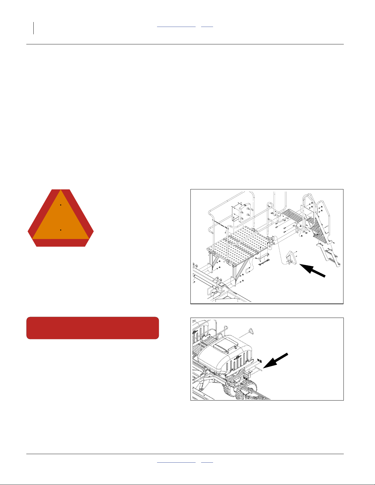
818-055C
Slow Moving Vehicle Reflector
On the back of the walkboard platform;
1 total
838-266C
Red Reflectors
On the back of seed box support structure each end
(above wheels, outside Daytime reflectors);
two total
25211
25206
401-406M Table of Contents Index 2014-07-14
Great Plains Manufacturing, Inc. Table of Contents Index Important Safety Information 7
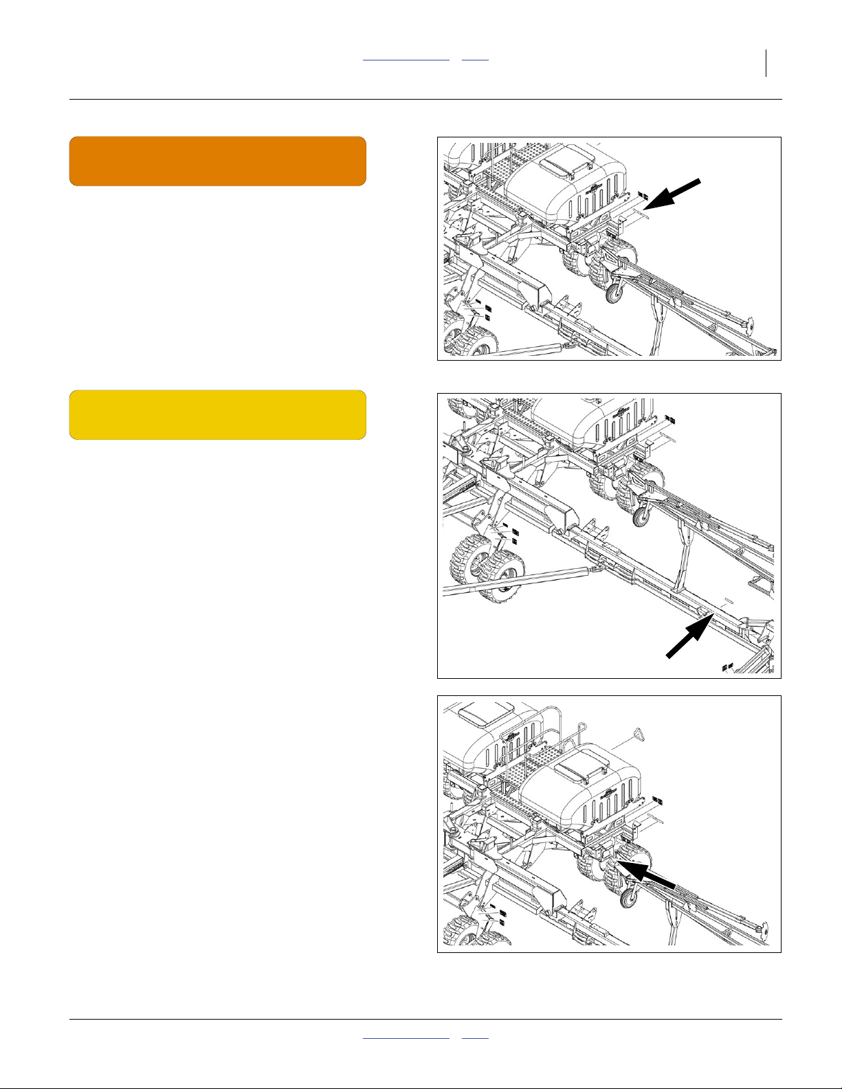
25206
838-267C
Daytime Reflectors
On the back of seed box support structure each end
(above wheels, inside of red reflectors);
two total
838-265C
Amber Reflectors
On the front of the center section front lower tool bars,
on the rear of the wing tool bars, and
on the sides of the seed box frame;
six total.
25206
25206
2014-07-14 Table of Contents Index 401-406M
8 YP2425 & YP2425F Table of Contents Index Great Plains Manufacturing, Inc.
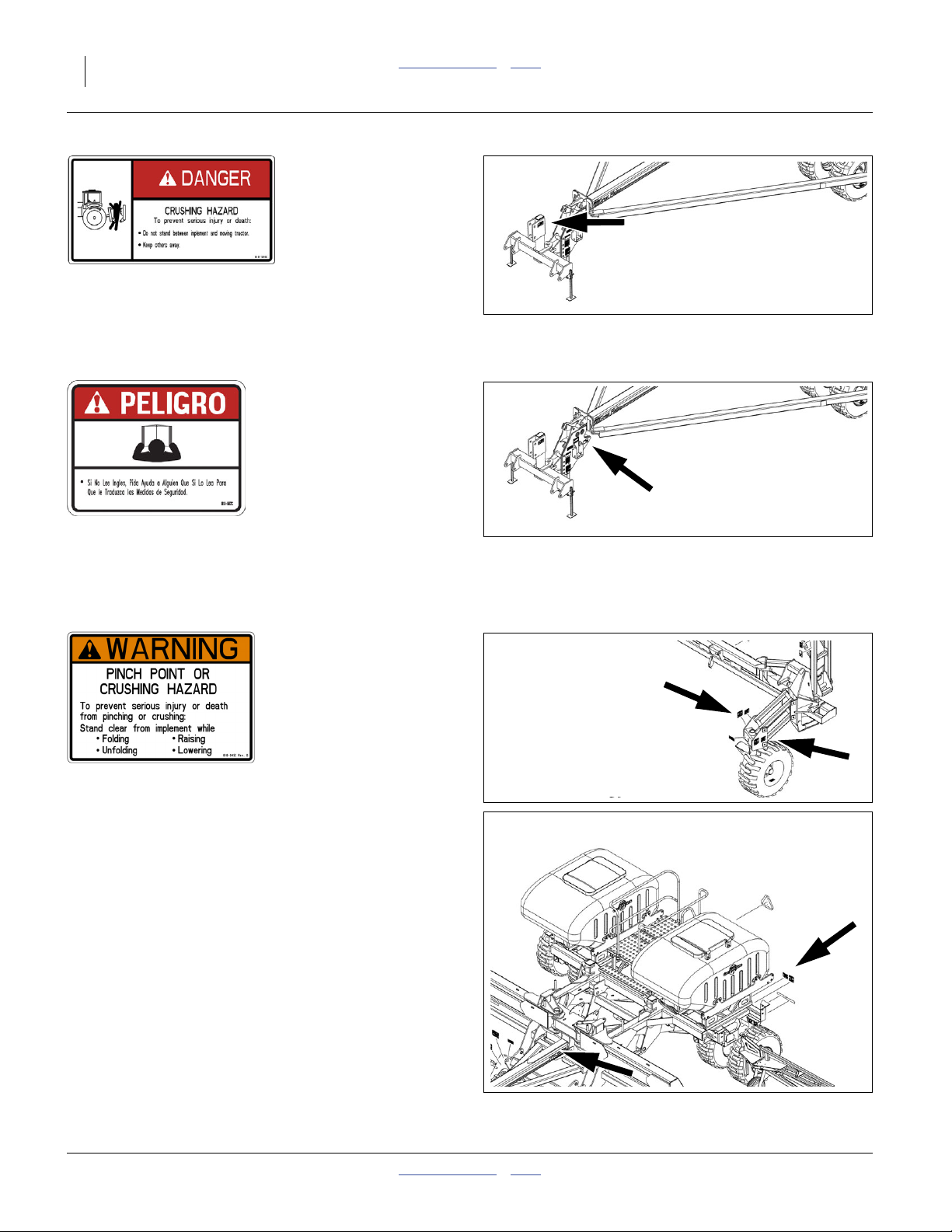
818-590C Danger: Crushing Hazard
Top center of 3-point hitch; one total
(not present with hydraulic tongue option)
818-557C Danger (in Spanish):
Advising non-English readers to seek translation
On side of tongue; one total
25206
25206
818-045C
25206
Warning: Pinch/Crush
On marker base, inside face, each end,
On forward transport wheel arms, each side
On rear axle by seed hopper, each side;
eight total
401-406M Table of Contents Index 2014-07-14
25206
Great Plains Manufacturing, Inc. Table of Contents Index Important Safety Information 9
WARNING
EXCESSIVE SPEED HAZARD
To Prevent Serious Injury or Death:
Do Not exceed 20 mph maximum transport
speed. Loss of vehicle control and/or machine
can result.
818-188C Warning: Speed
On front of center section, one total
818-188C Rev. C
25206
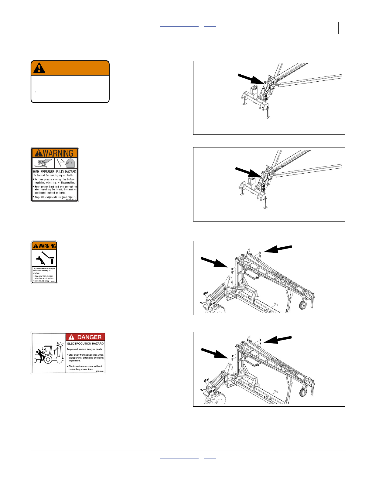
818-339C Warning: High Pressure Fluid Hazard
On side of tongue; one total
818-682C Warning: Markers: Pinch/Crush
One each side or marker upright arm, each side;
four total
838-599C Warning: Electrocution Hazard
One each side or marker upright arm, each side;
four total
25206
25206
25206
2014-07-14 Table of Contents Index 401-406M
10 YP2425 & YP2425F Table of Contents Index Great Plains Manufacturing, Inc.
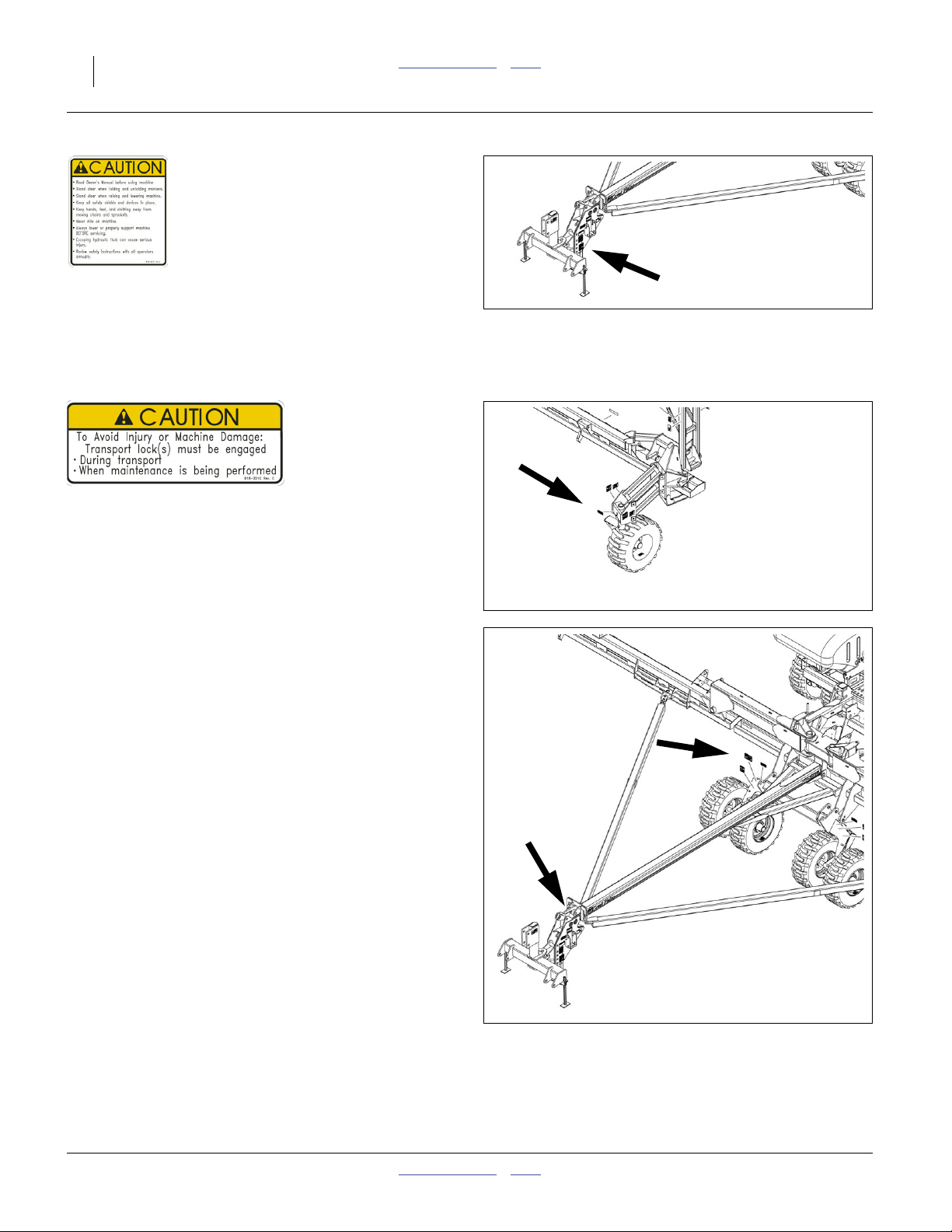
818-587C Caution: Read Operator’s Manual
On center tool bar; one total
818-351C Caution: Transport Locks
Hitch tongue; one total
25206
25206
25206
401-406M Table of Contents Index 2014-07-14
Great Plains Manufacturing, Inc. Table of Contents Index Important Safety Information 11
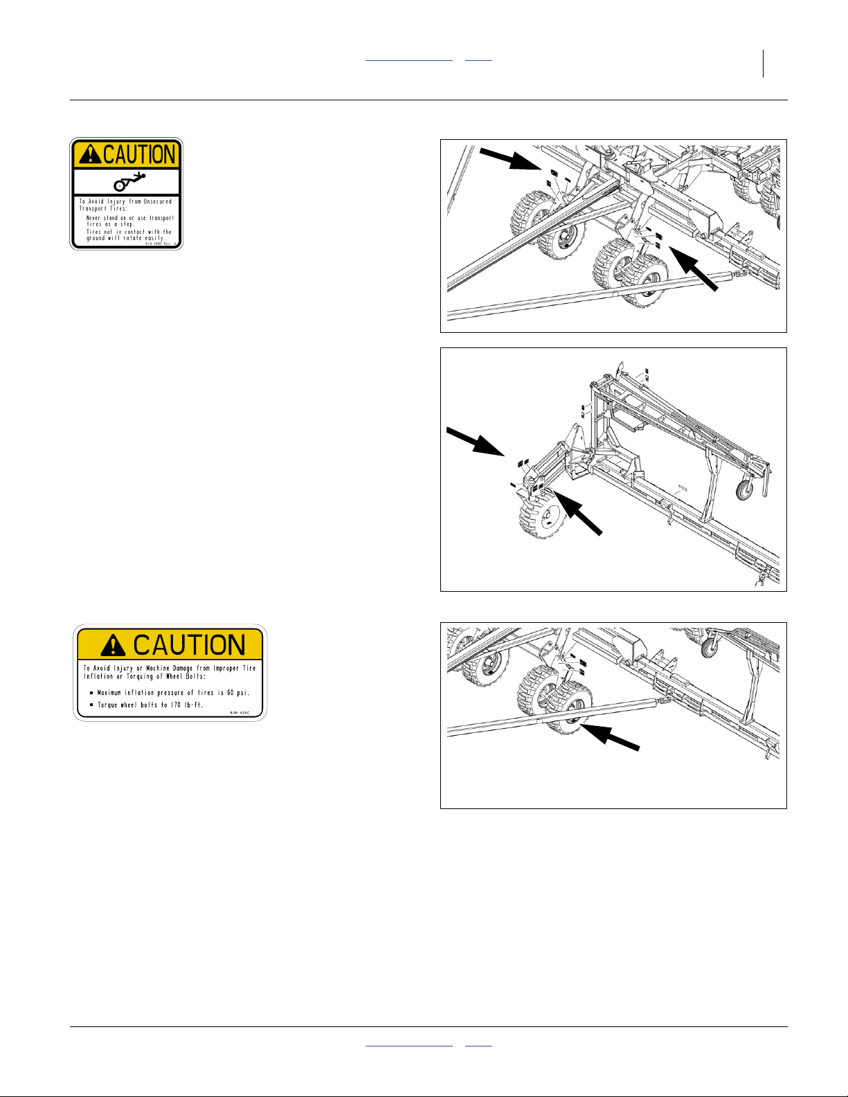
818-398C Caution: Tires Not A Step
One front face each wing gauge wheel,
One each side front center axle;
6 total
25206
25206
838-426C Caution: Pressure and Torque
On outside rim each transport tire;
10 total
2014-07-14 Table of Contents Index 401-406M
25206
12 YP2425 & YP2425F Table of Contents Index Great Plains Manufacturing, Inc.
Introduction
Great Plains welcomes you to its growing family of new
product owners. The 60 Foot Yield-Pro® Planter (YP24)
has been designed with care and built by skilled workers
using quality materials. Proper setup, maintenance, and
safe operating practices will help you get years of
satisfactory use from the machine.
Document Family
401-406M Owner’s Manual (this document)
401-406B Seed Rate Charts
401-406P Parts Manual
403-362M Dry Fertilizer Manual (YP2425F only)
110011375 DICKEY-john® seed monitor manual
110011439 5 inch VT MANUAL
110011440 10 inch VT MANUAL
110011429 YP2425-48TR Quick-Start guide
110011430 YP2425-4715 Quick-Start guide
110011431 YP2425-2430 Quick-Start guide
110011432 YP2425-3620 Quick-Start guide
110011433 YP2425-2470 Quick-Start guide
Description of Unit
The YP24 is a pull-type implement for use in
conventional till, minimum-till, or light no-till conditions.
The YP24 accepts optional unit mounted and
frame-mounted row accessories. Coulters make it
suitable for light to moderate no-till conditions only. The
YP24 is outfitted with 25 Series, side-depth-control
row-units supporting Singulator Plus or finger pickup
precision seed meters. The YP24 folds for transport.
Intended Usage
Use the YP24 to seed production-agriculture crops only.
Do not modify the planter for use with attachments other
than Great Plains options and accessories specified for
use with the YP24.
Models Covered
YP2425-2430 24 Row, 30 Inch Spacing
YP2425-2470 24 Row, 70 cm Spacing
YP2425F-2470 24 Row, 70 cm, Dry Fertilizer
YP2425-3620 36 Row, 20 Inch Spacing
YP2425-4715 47 Row, 15 Inch Spacing
YP2425-48TR 48 Row (24 Twin), 30 Inch Spacing
This manual covers all vintages of YP2425 planters but
does not include YP2425A (with Air-Pro® meters).
U
R
B
R
F
L
D
L
R
F
25205
U
B
L
D
Figure 1
YP2525 Planter
Using This Manual
This manual will familiarize you with safety, assembly,
operation, adjustments, troubleshooting, and
maintenance. Read this manual and follow the
recommendations to help ensure safe and efficient
operation.
The information in this manual is current at printing.
Some parts may change to assure top performance.
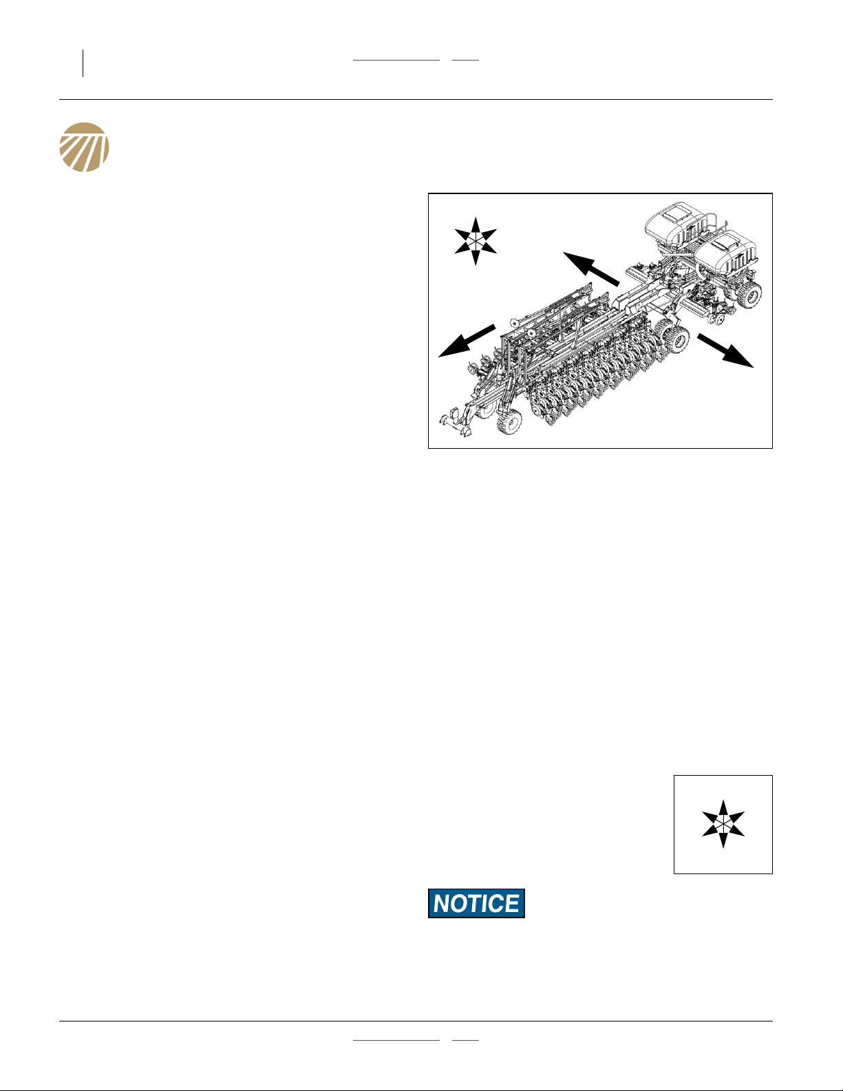
Definitions
The following terms are used throughout this manual.
The following terms are used throughout this manual.
Right-hand and left-hand as used in
this manual are determined by facing
the direction the machine will travel
while in use unless otherwise stated.
An orientation rose in some line art
illustrations shows the directions of:
Up, Back, Left, Down, Front, Right.
A crucial point of information related to the preceding topic.
Read and follow the directions to remain safe, avoid serious
damage to equipment and ensure desired field results.
Note: Useful information related to the preceding topic.
401-406M Table of Contents Index 2014-07-14

Great Plains Manufacturing, Inc. Table of Contents Index Introduction 13
Owner Assistance
If you need customer service or repair parts, contact a
Great Plains dealer. They have trained personnel, repair
parts and equipment specially designed for Great Plains
products.
Refer to Figure 2
Your machine’s parts were specially designed and
should only be replaced with Great Plains parts. Always
use the serial and model number when ordering parts
from your Great Plains dealer. The serial-number plate is
located on the left end of the seed cart tool bar, as
shown.
Record your YP24 model and serial number here for
quick reference:
Model Number:__________________________
Serial Number: __________________________
Your Great Plains dealer wants you to be satisfied with
your new machine. If you do not understand any part of
this manual or are not satisfied with the service received,
please take the following actions.
Figure 2
Serial Number Plate
26032
1. Discuss the matter with your dealership service
manager. Make sure they are aware of any
problems so they can assist you.
2. If you are still unsatisfied, seek out the owner or
general manager of the dealership.
For further assistance write to:
Product Support
Great Plains Mfg. Inc., Service Department
PO Box 5060
Salina, KS 67402-5060
785-823-3276
2014-07-14 Table of Contents Index 401-406M

14 YP2425 & YP2425F Table of Contents Index Great Plains Manufacturing, Inc.
Preparation and Setup
This section helps you prepare your tractor and YP24 for
use, and covers tasks that need to be done seasonally,
or when the tractor/planter configuration changes.
Before using the YP24 in the field, you must hitch the
planter to a suitable tractor, inspect systems, level the
planter. Before using the planter for the first time, and
periodically thereafter, certain adjustments and
calibrations are required.
Post-Delivery/Seasonal Setup
On initial delivery, use with a new tractor, and seasonally,
check and as necessary, complete these items before
continuing to the routine setup items:
• Install seed monitor console in tractor (page 140).
• Bleed hydraulic system (page 90).
• Wing leveling and alignment (page 92).
• Marker setup (page 53).
• Radar calibration (page 140).
• De-grease exposed cylinder rods if so protected at last
storage.
Pre-Planting Setup
Complete this checklist before routine setup:
❑ Read and understand “Important Safety
Information” on page 1.
❑ Check that all working parts are moving freely, bolts
are tight, and cotter pins are spread.
❑ Check that all grease fittings are in place and
lubricated. See “Lubrication and Scheduled
Maintenance” on page 100.
❑ Check that all safety decals and reflectors are
correctly located and legible. Replace if damaged.
See “Safety Decals” on page 6.
❑ Inflate tires to pressure recommended and tighten
wheel bolts as specified. See “Tire Inflation Chart”
on page 122.
401-406M Table of Contents Index 2014-07-14
Great Plains Manufacturing, Inc. Table of Contents Index Preparation and Setup 15
Hitching Tractor to Planter
Crushing Hazard:
Do not stand or place any part of your body between planter
and moving tractor. You may be severely injured or killed by
being crushed between the tractor and planter. Stop tractor
engine and set parking brake before attaching cables and
hoses.
High Pressure Fluid Hazard:
Relieve pressure before disconnecting hydraulic lines. Use a
piece of paper or cardboard, NOT BODY PARTS, to check for
leaks. Wear protective gloves and safety glasses or goggles
when working with hydraulic systems. Escaping fluid under
pressure can have sufficient pressure to penetrate the skin
causing serious injury. If an accident occurs, seek immediate
medical assistance from a physician familiar with this type of
injury.
Hitching with 3-Point
Refer to Figure 3
1. Connect your tractor 3-point to the planter 3-point
hitch. If using quick hitch be sure planter locks into
hitch securely.
2. Raise tractor 3-point just enough to relieve pressure
from parking stands.
3. Swing up and pin up 3-point stands. See “Storing
3-Point Parking Stands” on page 20.
Load Sway Risk:
Adjust 3-point hitch arms and sway blocks to minimize any
side-to-side sway to assure proper tracking in the field and
safe road travel.
4. Connect hydraulic hoses to tractor remotes. See
“Hydraulic Hose Hookup” on page 17.
5. Connect electrical cables. See “Electrical Hookup”
on page 19.
6. Remove and store main tongue parking stand. See
“Store Main Parking Stand” on page 19.
Figure 3
3-Point Hitching
21924
2014-07-14 Table of Contents Index 401-406M
16 YP2425 & YP2425F Table of Contents Index Great Plains Manufacturing, Inc.
Hitching with Hydraulic Tongue (Option)
Refer to Figure 4
1. Move the tractor to near hitching position.
2. Connect the hydraulic hoses for the tongue circuit.
This needs to be done before hitching in order to
raise and lower the tongue. See “Hydraulic Hose
Hookup” on page 17. Allow slack for hitch
movements. Close the tongue cylinder bypass valve.
3. Make electrical connections for at least the planter
control circuit (necessary to control planter hydraulic
systems). See page 19.
4. Check that hitch local bypass valve is closed.
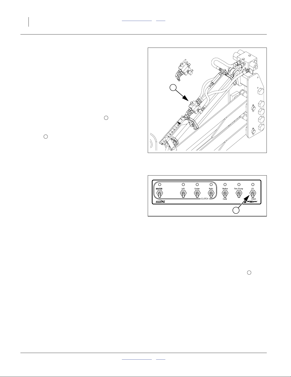
Refer to Figure 5
5. Set the cab Clutch Folding Module Lift/Hitch
switch to Hitch.
6. Retract the Hitch/Lift circuit to set the tongue height
to clear the draw-bar. Back the tractor into alignment
and pin the draw-bar.
7. Connect safety chain to a suitable anchor point on
the tractor.
8. Connect all other hydraulic hoses.
9. Connect any remaining electrical cables, page 19.
10. Extend the Hitch/Lift circuit to raise the hydraulic
tongue just enough to relieve pressure from the
parking stand.
11. Remove and store main tongue parking stand. See
“Store Main Parking Stand” on page 19.
2
1
1
Figure 4
Hitching with Hydraulic Tongue
(Bypass Valve Closed)
Figure 5
Clutch Folding Module (Hitch)
28477
2
26033
Raising/Lowering Tongue
In addition to hitching, tongue raising and lowering is
required during fold and unfold to engage and disengage
the wing locks.
With the standard 3-point hitch, the planter tongue is
raised and lowered by raising and lowering the 3-point.
With the optional hydraulic tongue, the planter tongue is
raised by extending the hitch cylinder, and lowered by
retracting the hitch cylinder.
401-406M Table of Contents Index 2014-07-14
Local Float on Hydraulic Tongue
Refer to Figure 4
The hydraulic tongue must be in Float during planter
moves.
If it is necessary to move the planter without first
connecting it to a tractor that has a float-capable circuit
for the hydraulic tongue, open the bypass valve on the
tongue cylinder. This provides local floating capability at
the tongue.
1
Great Plains Manufacturing, Inc. Table of Contents Index Preparation and Setup 17
Hydraulic Hose Hookup
High Pressure Fluid Hazard:
Relieve pressure before disconnecting hydraulic lines. Use a
piece of paper or cardboard, NOT BODY PARTS, to check for
leaks. Wear protective gloves and safety glasses or goggles
when working with hydraulic systems. Escaping fluid under
pressure can have sufficient pressure to penetrate the skin
causing serious injury. If an accident occurs, seek immediate
medical assistance from a physician familiar with this type of
injury.
Only trained personnel should work on system hydraulics!
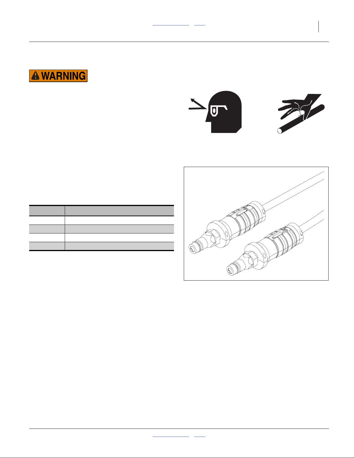
Refer to Figure 6
Great Plains hydraulic hoses have color coded handle
grips to help you hookup hoses to your tractor outlets.
Hoses that go to the same remote valve are marked with
the same color.
Current Style Color Coded Hose Handles
Color Hydraulic Function
Gray Wing Fold / Marker Fold / Auxiliary
Blue Lift / (and Hitch if hydraulic tongue)
Black Fan
Yellow Hydraulic Drive
To distinguish hoses on the same hydraulic circuit, refer
to the symbol molded into the handle grip. Hoses with an
extended-cylinder symbol feed cylinder base ends.
Hoses with a retracted-cylinder symbol feed cylinder rod
ends.
For hydraulic fan and drive motors, connect the hose
under the retracted cylinder symbol to the pressure side
of the motor. Connect the hose under the extended
cylinder symbol to the return side of the motor.
The fan motor further requires hookup of a third line,
which returns hydraulic fluid from the fan motor case.
Figure 6
Color Coded Hose Handles
31733
2014-07-14 Table of Contents Index 401-406M

18 YP2425 & YP2425F Table of Contents Index Great Plains Manufacturing, Inc.
Older Style Hose Handles with Color Ties
Refer to Figure 7
Great Plains hydraulic hoses are color coded to help you
hookup hoses to your tractor outlets. Hoses that go to
the same remote valve are marked with the same color
tie.
Color Hydraulic Function
White Wing Fold / Marker Fold / Auxiliary
Blue Lift / (and Hitch if hydraulic tongue)
Orange Fan
Yellow Hydraulic Drive
To distinguish hoses on the same hydraulic circuit, refer
to hose label. The hose under an extended-cylinder
symbol feeds a cylinder base end. The hose under a
retracted-cylinder symbol feeds a cylinder rod end.
For hydraulic fan and drive motors, connect the hose
under the retracted cylinder symbol to the pressure side
of the motor. Connect the hose under the extended
cylinder symbol to the return side of the motor.
The fan motor further requires hookup of a third line,
which returns hydraulic fluid from the fan motor case.
Figure 7
Older Style Hoses w/Label
27270
Protecting Fan Hydraulic Motor Seals
Low Pressure (Case) Drain Connection
1. Attach case drain hose to low pressure drain
connection.
Note: Case drain hose has the smaller1⁄4inch I.D. hose
and small, flat-face, connector.
2. Connect low pressure motor return hose to low
pressure return connector. It is distinguished by a
large (1.06 inch/2.7 cm diameter) quick coupler.
3. Connect hydraulic hoses to tractor remotes.
Motor Seal Damage Risk:
Case Drain Hose must be attached first,
prior to inlet and return hoses being connected.
Case Drain Hose must be detached last,
to prevent damage to the fan motor.
Hydraulic Motor Performance Risk:
DO NOT hook case drain line to a “power-beyond port”.
401-406M Table of Contents Index 2014-07-14
Great Plains Manufacturing, Inc. Table of Contents Index Preparation and Setup 19
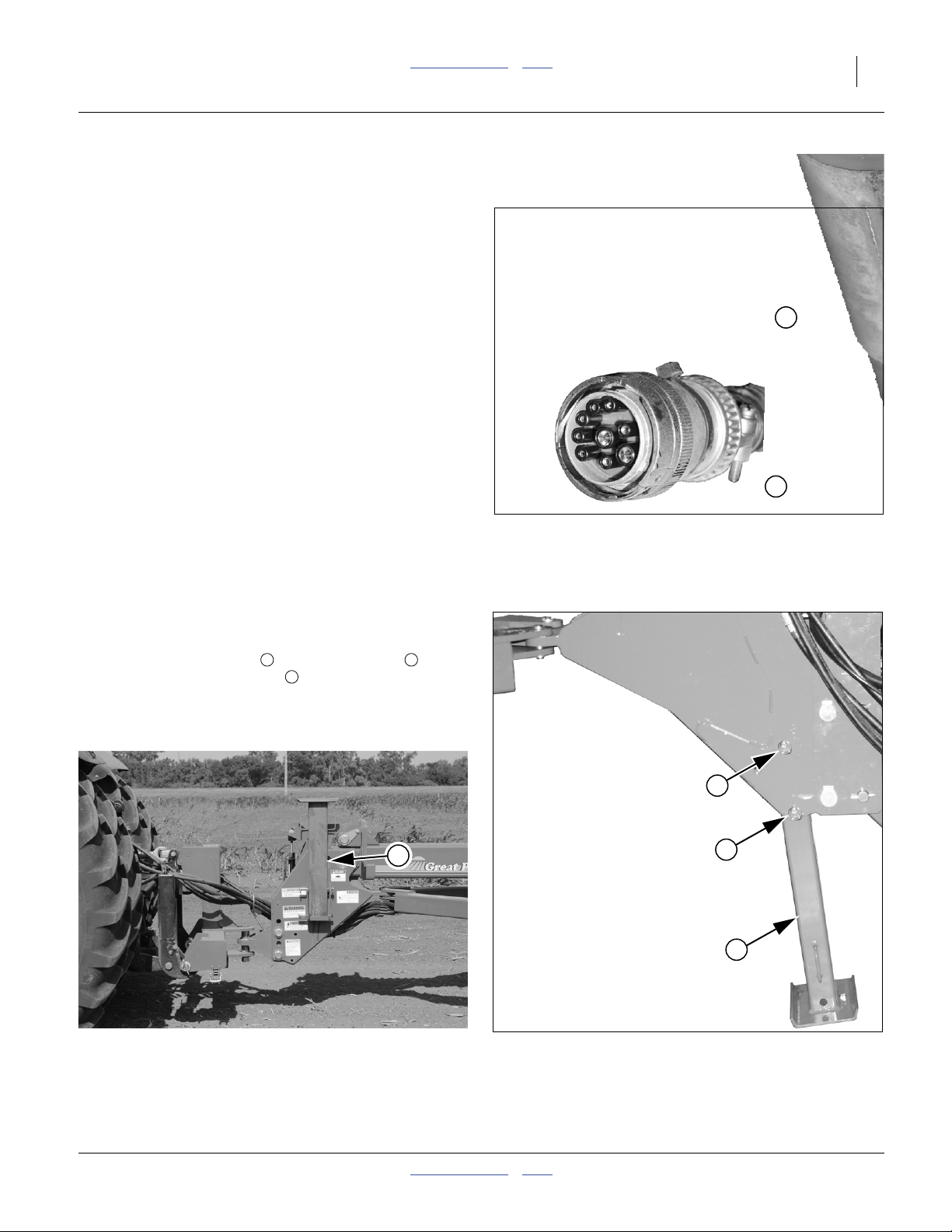
Electrical Hookup
Refer to Figure 8
Your YP24 is equipped with standard and optional
devices that require separate electrical
connections.Make sure tractor is shut down with
accessory power off before making connections.
These connections may be made in any order.
Note: The switch control module should be mounted in
your tractor cab in a location with easy access.
Route wiring harnesses with enough slack to allow
for tractor movement, especially on articulating
tractors.
1
2
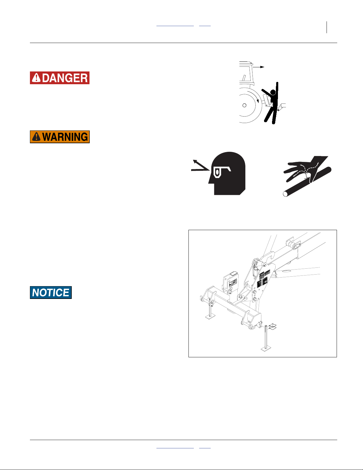
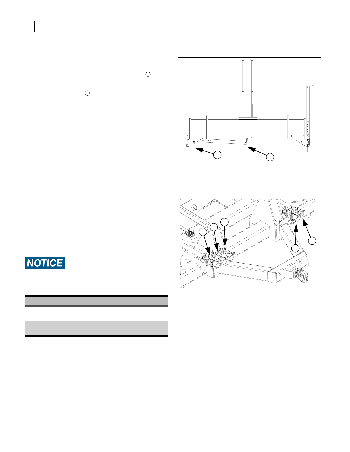
Store Main Parking Stand
Refer to Figure 9 and Figure 10
1. Remove the lower pin and the upper pin
holding the parking stand .
2. Move the stand from under the tongue to an inverted
position in the bracket on the left side on the tongue.
1 2
3
3
Figure 8
Connector Identification
2
1
3
25236
25237
Figure 10
Parking Jack Stored
2014-07-14 Table of Contents Index 401-406M
29242
Figure 9
Main Parking Stand
26110
20 YP2425 & YP2425F Table of Contents Index Great Plains Manufacturing, Inc.
Storing 3-Point Parking Stands
Refer to Figure 11 (shown without tractor for clarity)
1. For the standard 3-point hitch, store stands by
either of the following methods:
4
Remove lower pins . Swing stand under hitch.
Reinsert pin beneath stand at inner hole.
Remove both pins. Invert stand. Re-pin.
2. Adjust the top link of a 3-point long enough so the
ball swivel does not bottom out when fully raised.
3. Secure hoses so they do not get caught in ball
swivel. Failure to do so could cause hose to be
crushed requiring hose replacement.
5
Tank Cart Hitching
If using a fertilizer cart, consult the cart manual for:
• hitching cart tongue to planter
• connecting pump control electronics to planter
• connecting fertilizer feed hoses to planter
Complete the tractor-planter hook-up before making any
tank cart connections.
5
Figure 11
Storing 3-Point Stands
4
29732
R
C
L
G
S
Open hose and inlet valves when ready to begin planting.
Close them when not in use.
Fertilizer Connection Types
Type
2-section, planter manifold and pump:
2
Starter inlet only
3-section, cart manifold and pump:
3
Left, Center, Right inlets & Gauge line
401-406M Table of Contents Index 2014-07-14
Description
Figure 12
Fertilizer Cart Connections
27372
Great Plains Manufacturing, Inc. Table of Contents Index Preparation and Setup 21
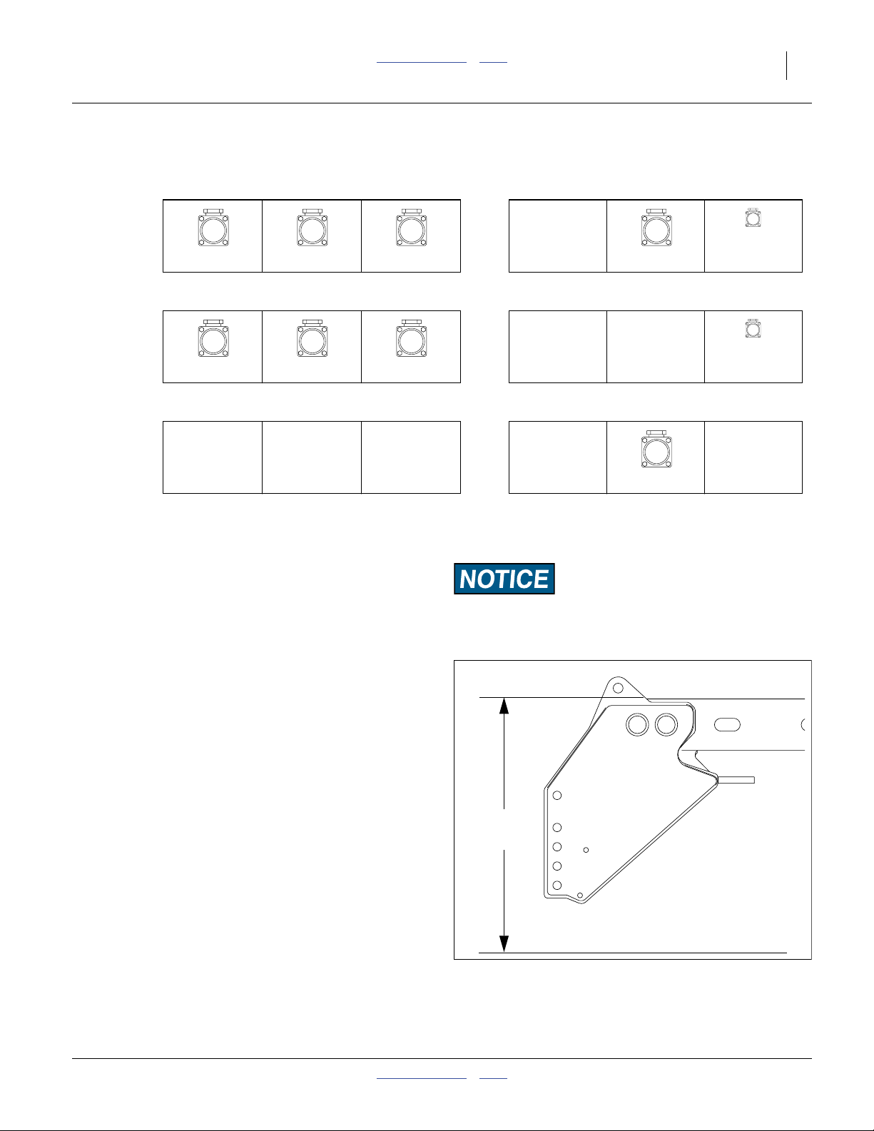
Making Fertilizer Connections
YP2425 Planter with Type 2 and Type 3 Manifolds, & Ground Drive Pump(s)
Planter Inlet
L
C
R
Left Type 3 Center Type 3 Right Type 3 Type 2
YP2425 Planter with Type 3 Manifold (only)
Planter Inlet
L
C
R
Left Type 3 Center Type 3 Right Type 3
YP2425 Planter with Type 2 (only) & Ground Drive Pumps
Planter Inlet
a. Gauge Line is supplied with PFC1600 or PFC2000 tank cart
Heights and Leveling
All frame sections must be at the correct height and level
to maintain even planting depth.
Periodic frame-leveling adjustments should not be
necessary. If you are having problems with uneven
depth, check planter levelness and follow these
procedures.
1. Before making any adjustments be sure the lift
cylinders are re-phased and operating properly. If
not, “Re-Phasing Lift System” on page 32
2. Complete “Bleeding Hydraulics” on page 90.
3. Unfold the planter fully (page 26).
S
G
Gauge Line
Gauge Line
a
G
a
S
Type 2
Field Results Risk:
Level frame in planting conditions. Failure to do so may result
in implement not producing desired results.
Set Tongue Height
Planter must be unfolded for this procedure.
Refer to Figure 13
Set the initial tongue height, using 3-point or hydraulic
tongue cylinder. Distance is measured at top of tongue to
ground level.
• For standard 3-point hitch:
Set depth stop to capture this working height.
If desired height cannot be attained with normal range
of hitch, swivel coupler weldment may be relocated in
tongue bolt holes.
2014-07-14 Table of Contents Index 401-406M
41.5 in.
(105.4 cm)
Figure 13
Initial Tongue Height
25316
22 YP2425 & YP2425F Table of Contents Index Great Plains Manufacturing, Inc.
Note: Tractor 3-point control must be in Depth Control
mode, and not Draft Control mode.
• For hydraulic tongue:
Note the scale reading on the tongue for this height.
[Re]set the tongue height to this value when planting.
Checking Planter Leveling Side to Side
The planter is designed to operate with all sections of the
main tool bar nominally 26 inches (66 cm) above the
planting surface. The height of the center section is not
routinely adjustable. Set planting depth with row unit
adjustments.
When lowering the planter for the first time on the
planting ground:
1. Completely lower the main tool bar. If necessary, first
lift off transport locks, remove and stow locks.
2. Set hitch to planting height.
3. Pull forward a short distance.
Planter must be fully lowered to field position (with openers
into ground) and hitch height must be set before making
side-to-side adjustments.
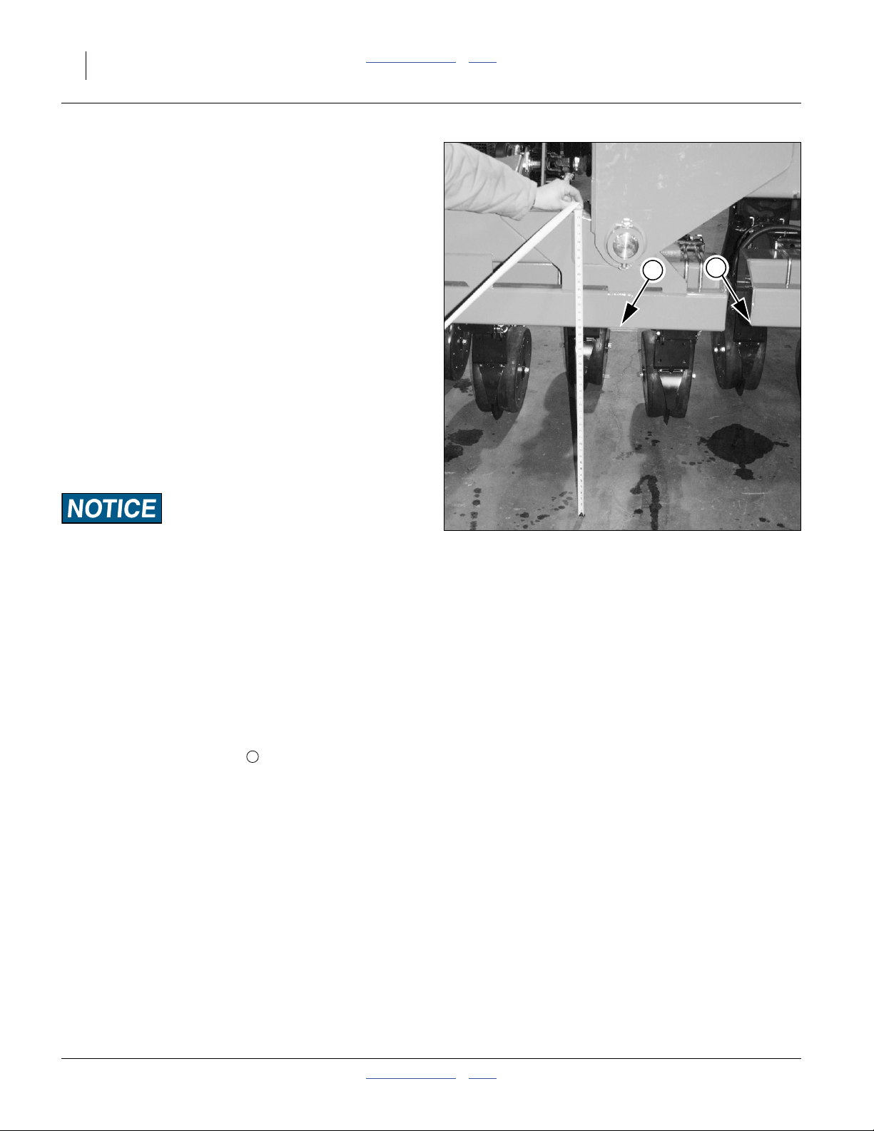
Center Section Level Check
Vertical height and side-to-side level of the center section
is set at the factory and cannot be field-adjusted. It does
need to be verified before checking/adjusting the wings.
Soil accumulation on the wheels, for example, can cause
the center section to tilt.
Refer to Figure 14 on page 22
4. Measure the elevation of both left and right sides of
the planter center section, at the ends of the center
section tool bar (location in Figure 14).
1
2
Figure 14
Wing/Center Level Check
Note: Any unevenness in ground that tilts the wings or
center section causes the inner wing ends to
move up or down slightly with respect to the center
frame.
1
26117
401-406M Table of Contents Index 2014-07-14
Great Plains Manufacturing, Inc. Table of Contents Index Preparation and Setup 23
Wing Leveling
Wing Leveling, Inboard End
Wing leveling check/adjustment is required prior to first
use of the YP24, and periodically thereafter, for example,
if soil conditions change dramatically.
Before performing this operation:
• Check center section height and level (page 21).
• Row unit coulter/planting depths, and row unit
down-pressures must all be equal.
5. Measure the height of the inboard end of each wing,
near the wing flex pivot (location in Figure 14).
6. Compare this height to that of the center section
obtained at step 4 on page 22.
7. If the heights differ by more than 1 inch, check them
again after leveling the wing ends. If they still differ,
the thrust washers in the wing pivots may be worn
and in need of replacement
2
3
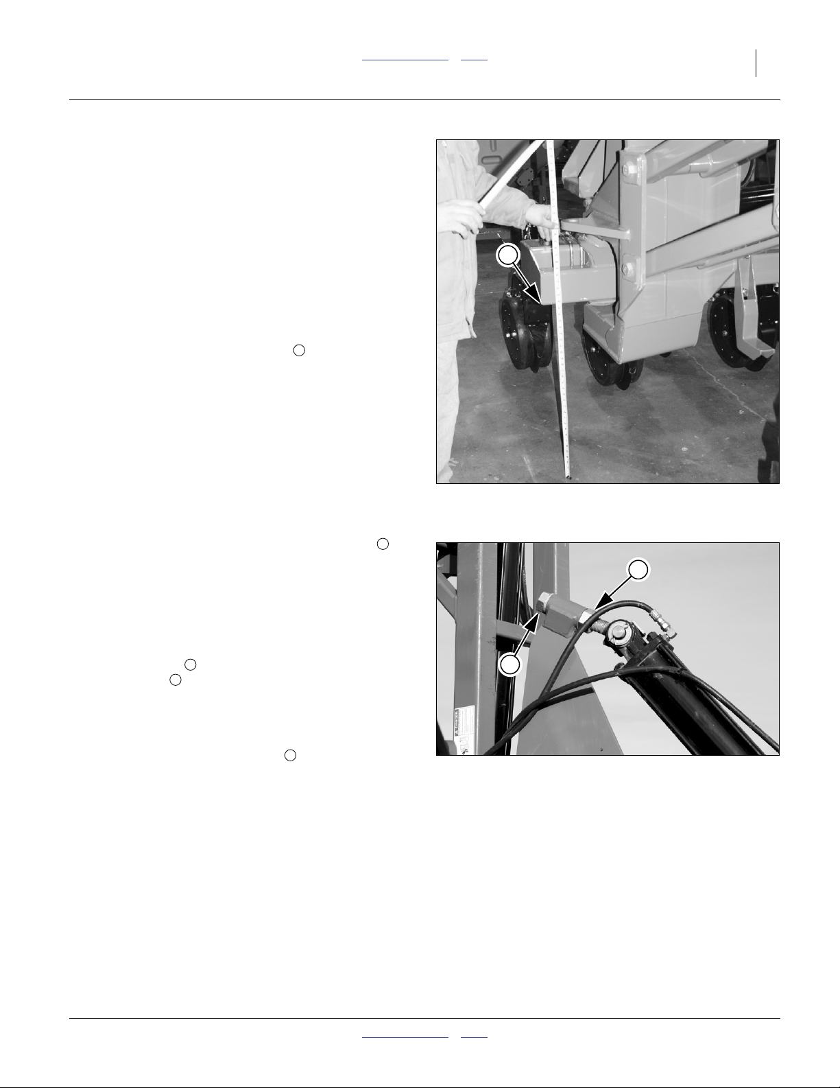
Wing Leveling, Outboard End
Refer to Figure 15 and Figure 16
1. Measure from the bottom of the wing tool bar to the
ground at the outer end of each wing (location in
Figure 15).
2. Compare to the measurement at the outer end of the
center tool bar, at the wing pivot location. All
measurements should be identical, and close to
26 inches (66 cm).
3. If measurements do not match, loosen upper gauge
wheel lock nut , and adjust eyebolt link length with
adjuster nut .
4. If adjustments are needed on either side, re-check
the other side after each adjustment, and re-adjust it
as needed.
5. Once level, tighten the lock nut .
1
2
1
3
Figure 15
Wing End Level Check
1
Figure 16
Leveling Wing
26118
2
26036
2014-07-14 Table of Contents Index 401-406M

24 YP2425 & YP2425F Table of Contents Index Great Plains Manufacturing, Inc.
Lock Up Fertilizer Drive
YP2425 serial number A1072Q+
Loss of Control and Sharp Object/Crushing Hazards:
Do not lift or lower wheel by spoke or rim; use handle only.
Keep feet out from under wheel. 90 pounds (41 kg.) force is
required to lift wheel. If you lose your grip before pinning, or
after unpinning, the arm snaps down rapidly. The traction
teeth and the force of the wheel impact can inflict serious
injury.
The liquid fertilizer option uses a piston pump driven by a
ground contact wheel. When not using the fertilizer drive,
preserve the pump by locking up the ground wheel. On
older models remove the chain.
Note: Do not operate planter pump when not applying
material.
Refer to Figure 17
For YP2425 planters:
6. Remove clevis pin from storage hole .
7. Release the lock arm , lift handle to lift ground
wheel up to position it in-between lock arm.
8. Secure with pin clevis and cotter pin.
5 7
6
4
5
4
7
Locked Up Fertilizer Drive
6
Figure 17
32364
401-406M Table of Contents Index 2014-07-14

Great Plains Manufacturing, Inc. Table of Contents Index 25
Operating Instructions
This section covers general operating procedures.
Experience, machine familiarity, and the following
information will lead to efficient operation and good
working habits. Always operate farm machinery with
safety in mind.
Pre-Start Checklist
Perform the following steps before transporting the YP24
to the field.
High Pressure Fluid Hazard:
Relieve pressure before disconnecting hydraulic lines. Use a
piece of paper or cardboard, NOT BODY PARTS, to check for
leaks. Wear protective gloves and safety glasses or goggles
when working with hydraulic systems. Escaping fluid under
pressure can have sufficient pressure to penetrate the skin
causing serious injury. If an accident occurs, seek immediate
medical assistance from a physician familiar with this type of
injury.
❑ Carefully read “Important Safety Information” on
page 1.
❑ Install seed rate meters appropriate for crop. To
change meters, see “Seed Meter Setup and
Adjustment” on page 75.
❑ Install seed wheels appropriate for crop. To change
wheels, see “Singulator Plus™ Meter Wheel
Replacement” on page 77. With finger meters,
make sure correct 6- or 12-finger units are installed
for the intended row spacing.
❑ Lubricate planter as indicated under “Lubrication
and Scheduled Maintenance” on page 100.
❑ Check all tires for proper inflation. See “Tire
Inflation Chart” on page 122.
❑ Check all bolts, pins, and fasteners. Torque as
shown in “Torque Values Chart” on page 123.
❑ Check planter for worn or damaged parts. Repair or
replace parts before going to the field.
❑ Check hydraulic hoses, fittings, and cylinders for
leaks. Repair or replace before going to the field.
2014-07-14 Table of Contents Index 401-406M
26 YP2425 & YP2425F Table of Contents Index Great Plains Manufacturing, Inc.
Unfolding The YP24
The distance between the tractor and the seed structure
decreases by 12 feet (3.7 m) during unfolding. Planter,
tractor, or both will move during this operation.
Crushing, Pinch-Point and Overhead Hazards:
To prevent serious injury or death:
▲ Fold only on hard level ground. Allow ample room.
▲ If it is desired that the tractor not move, make sure tractor is
in Park and/or has parking brakes set, otherwise the
telescoping movement of the planter is likely to result in
tractor movement.
▲ Do not allow anyone to be on or near the planter during
unfolding.
▲ Stay clear of the wing sweep arcs. The sweep arcs of the
wings have numerous pinch and crush points in the
mechanism. Coulters and row openers are sharp.
▲ Allow no one near planter. The seed structure usually
moves forward during unfolding.
▲ Do not unfold with planter lowered, or machine damage
will result.
▲ Unfold only with markers resting in transport cradles.
▲ Unfold only if hydraulics are bled free of air and fully
charged with hydraulic oil.
1. Move to level ground.
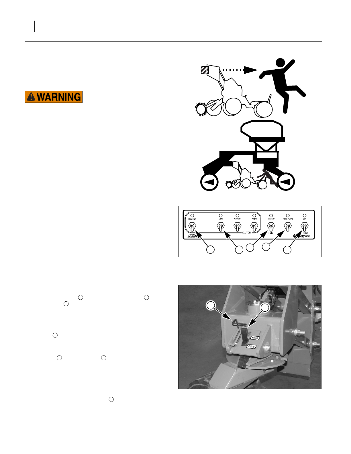
Refer to Figure 18
2. On the Clutch Folding Module (CFM), set the
following switches to OFF (down):
MASTER switch in the CLUTCH cluster , and
Fert.Pump .
3. If the folded planter is lowered, raise mainframe (see
“Raising/Lowering Planter” on page 28).
4. If equipped with hydraulic hitch, the CFM Lift/Hitch
switch must be set to Hitch.
Refer to Figure 19
5. At each wing caster, check that lock control
handles and indicators are in the ROAD
position, allowing the casters to swivel. If they are
not, set handle to ROAD position and fully raise and
lower planter to release load on lock plates to allow
them to come open.
Refer to Figure 18
6. Set CFM Marker/Fold switch to Fold. LED above
switch blinks continuously.
5
6 7
1 2
3
4
1
2
Figure 18
Clutch Folding Module
6
Figure 19
Caster Unlocked
3
4
5
26111
7
29306
401-406M Table of Contents Index 2014-07-14
 Loading...