

Page 1

Table of Contents Appendix A
Manufacturing, Inc.
www.greatplainsmfg.com
Seed and Fertilizer Rate Charts for the YP2425A Yield-Pro® Planter with Air-Pro® seed meters
The following pages are to assist in the proper setting of seeding and
fertilizer rates for the 60-foot (18m) two-section Yield-Pro® Planter with
Air-Pro
Plains recommends checking singulated rates.
®
meters. To assure the most accurate seeding rates, Great
ORIGINAL INSTRUCTIONS
EN
© Copyright 2012 Printed 2012-02-29 401-626B
Page 2

Great Plains Mfg., Inc. Cover ii
Table of Contents
Introduction ..................................................................1
Models Covered .............................................................1
Document Family ........................................................... 1
Rate Setting Overview .................................................2
Setting Planting Rate......................................................2
Setting Fertilizer Rate.....................................................2
Population Reference Information..................................2
Kernels Per Pound...........................................................2
Seeds Per Unit ............................................................... 2
Seed Spacing ................................................................. 2
Spacing (U.S. Customary units, page 1 of 2) ......... 3
Air-Pro® Meter Disk Selection ........................................5
Meter Pressurization ......................................................8
Initial Meter Pressurization: Cotton.............................8
Initial Meter Pressurization: Milo.................................8
Initial Meter Pressurization: Soybeans .......................8
Initial Meter Pressurization: Sunflower .......................8
Initial Meter Pressurization: Round Corn........................ 8
Initial Meter Pressurization: Flat Corn ............................ 9
Factory Default Air Control Channel Screens ................ 9
Material 16 Setup.............................................................9
Control Channel 2 Setup .................................................9
Checking Planting Rate................................................10
Checking Singulated Rates .......................................... 10
Planting Rate ..............................................................12
Hydraulic Drive Meter Rate ..........................................12
Meter RPM Limit Charts ............................................... 13
Meter RPM Limits: Corn 24 Cell................................... 13
Meter RPM Limits: Corn 40 Cell................................... 14
Meter RPM Limits: Cotton 60 Cell ................................ 15
Meter RPM Limits: Milo 65 Cell .................................... 16
Meter RPM Limits: Milo 130 Cell .................................. 17
Meter RPM Limits: Soybeans 84 Cell........................... 18
Meter RPM Limits: Soybeans 168 Cell......................... 19
Meter RPM Limits: Sunflower 24 Cell........................... 20
Sprocket Indexing (Stagger) .....................................22
Indexing Preparation ....................................................23
Basic Indexing .............................................................. 23
Indexing Fine Adjustment.............................................25
Sprocket Indexing Charts ............................................. 26
30 inch Twin Row Sprocket Indexing ........................... 27
Volumetric Seeding....................................................28
General Information......................................................28
Related Documents ..................................................... 28
Clean-Out Meters......................................................... 28
Grain Shield ................................................................. 29
Install Discs / Set Shutters ........................................... 29
Take Note of Meter Pressure....................................... 30
Initial Meter Pressurization: Wheat ............................... 30
Calibrate....................................................................... 30
Furrow Checking Rate ................................................. 31
IntelliAg® Hydraulic Drive............................................. 32
Set Up A Material.......................................................... 33
Calibrate Speed Sensor................................................ 37
Meter RPM Limits: Volumetric ......................................38
Fertilizer Rate ............................................................. 39
Orifice Plate Selection.................................................. 39
Determine Orifice Size .................................................. 40
Strainer .........................................................................41
Ground Drive Fertilizer Rate ........................................ 42
JohnBlue Pump Rate.................................................... 42
JohnBlue Fertilizer Rates ..............................................43
JohnBlue Reference Data .............................................43
Setting Relief Valve.......................................................44
Appendix A ................................................................. 45
Seed Lubricants ........................................................... 45
Appendix B - Metric Charts....................................... 47
Disk Selection - Corn (metric) ...................................... 47
Disc Selection - Milo & Soybean (metric)..................... 48
Disc Selection - Sunflower, Volumetric, Blank ............. 49
Seed Spacing - Metric.................................................. 50
Meter Pressurization - Metric ....................................... 52
Initial Meter Pressurization: Cotton .......................... 52
Initial Meter Pressurization: Milo .............................. 52
Initial Meter Pressurization: Soybeans..................... 52
Initial Meter Pressurization: Sunflower..................... 52
Initial Meter Pressurization: Round Corn ...................... 52
Initial Meter Pressurization: Flat Corn........................... 53
Sprocket Indexing Charts - Metric................................ 54
Furrow Check - Metric.................................................. 56
Meter RPM Limit - Metric ............................................. 57
Volumetric - Metric Charts ........................................ 65
Volumetric Furrow Checking Rate - Metric ..................66
Volumetric Meter RPM Limits - Metric ......................... 67
© Copyright 2005, 2006, 2007, 2008, 2009, 2010, 2011, 2012. All rights Reserved
Great Plains Manufacturing, Inc. provides this publication “as is” without warranty of any kind, either expressed or implied. While every precaution has
been taken in the preparation of this manual, Great Plains Manufacturing, Inc. assumes no responsibility for errors or omissions. Neither is any liability
assumed for damages resulting from the use of the information contained herein. Great Plains Manufacturing, Inc. reserves the right to revise and improve its products as it sees fit. This publication describes the state of this product at the time of its publication, and may not reflect the product in the
future.
2012-02-29 Cover 401-626B
Trademarks of Great Plains Manufacturing, Inc. include: Singulator Plus, Swath Command, Terra-Tine.
Registered Trademarks of Great Plains Manufacturing, Inc. include:
Air-Pro, Clear-Shot, Discovator, Great Plains, Land Pride, MeterCone, Nutri-Pro, Seed-Lok, Solid Stand,
Terra-Guard, Turbo-Chisel, Turbo-Chopper, Turbo Max, Turbo-Till, Ultra-Till, Verti-Till, Whirlfilter, Yield-Pro.
Brand and Product Names that appear and are owned by others are trademarks of their respective owners.
Printed in the United States of America
Page 3
Great Plains Manufacturing, Inc. Table of Contents Metric Charts 1
Introduction
This manual covers the following tasks for 60-foot
three-section Yield-Pro®Planters equipped with Air-Pro
seed meters:
• setting and checking seed rate for singulated crops
• applying liquid fertilizer from optional tanks on-board
the planter, or from a trailing cart.
This manual is your guide to planter adjustments for
achieving specific seed population targets. It also
includes information you may need to properly setup and
adjust a separately provisioned fertilizer tank and pump
system.
Although some setup/adjustment material herein is
repeated from the Operator’s Manual, you need to be
thoroughly familiar with planter operations and
adjustments before applying this Seed Rate manual and
its table data.
Models Covered
YP2425A-2430 24 Row, 30 inch Spacing
YP2425A-2470 24 Row, 70 cm Spacing
YP2425A-3620 36 Row, 20 inch Spacing
YP2425A-4715 47 Row, 15 inch Spacing
YP2425A-48TR 48 Row (24 Twin), 30 inch Spacing
®
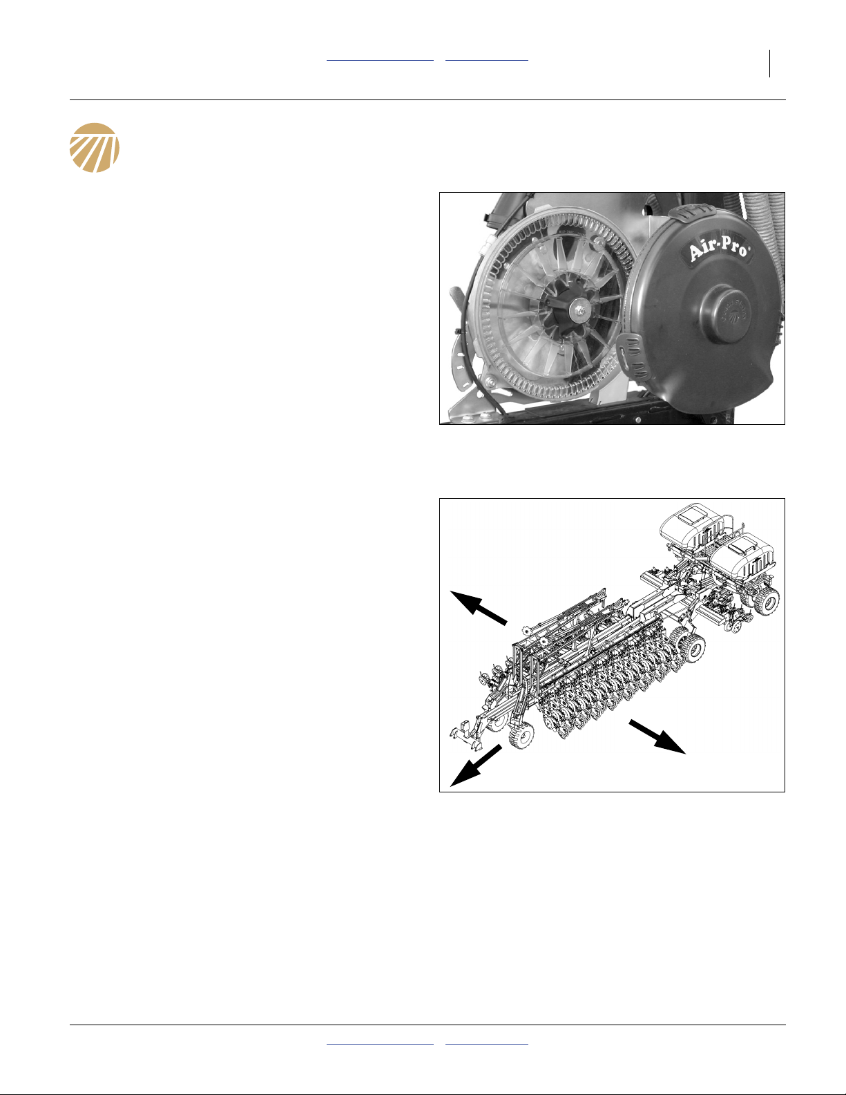
Figure 1
Air-Pro® Seed Meter
29626
R
Document Family
401-626M Owner’s Manual (this document)
401-626B Seed Rate Charts
401-626P Parts Manual
DICKEY-john®IntelliAg® manuals:
110011508 Planter/Drill Control, User Level 1
110011501 Planter/Drill Control, User Level 2&3
110011518 YP2425A-48TR Quick-Start Guide
110011519 YP2425A-4715 Quick-Start Guide
110011520 YP2425A-2430 Quick-Start Guide
110011521 YP2425A-3620 Quick-Start Guide
110011522 YP2425A/AF-2470 QSG
Figure 2
Yield-Pro® Planter
L
29711
2012-02-29 Table of Contents Metric Charts 401-626B
Page 4
2 YP2425A Table of Contents Metric Charts Great Plains Manufacturing, Inc.
Rate Setting Overview
Setting Planting Rate
There are five or six steps to obtaining the desired
number of seeds per acre, depending on row
configuration. This data applies to the Air-Pro
when planting at one
1. For your crop, determine your intended population, in
seeds/acre or seeds/hectare. If you know only the
seed spacing or pounds/acre (kg/hectare), consult
the charts on page 2 through page 4.
2. For your crop, population and desired field speed,
verify the suitability and setup of your seed disk:
See “Air-Pro® Meter Disk Selection” on page 5.
3. Set initial seed inlet shutter per seed rate chart.
Set initial meter pressurization per page 8, 9.
4. Sprocket index for staggered twin-row
Twin-row planters, with certain crops, get maximum
benefit with precise seed spacing between adjacent
rows. See “Indexing Fine Adjustment” on page 25.
5. Set meter rate
This is done via the seed monitor. Once data about
your planter is entered, you select the seed rate
directly. Consult the manual for the seed monitor.
6. Check planting rate
See “Checking Planting Rate” on page 10.
a. Volumetric planting (more than one seed per cell), is not
covered by this manual.
a
seed per disc cell.
®
meter
Setting Fertilizer Rate
If your planter is equipped with one or both optional
fertilizer manifold systems, it does not include the tank.
If the planter has a Type 2b (formerly referred to as a
“starter”) manifold, it may rely on an off-planter pump, or
may use one or two ground drive pumps on the planter.
See “Ground Drive Fertilizer Rate” on page 42 for
ground drive pump configuration.
If the planter has a Type 3
“hi rate”) manifold, it relies on an off-planter pump,
typically the pump on a Great Plains PFC1600 or
PFC2000 tank cart.
Rate setting for the cart pump is found in the cart’s
Operator manual.
Rate is controlled by the pump. Consistent distribution
requires using the correct size orifices in the manifolds. If
the orifice size is too large, flow may not be even across
all rows. If the orifice size is too small, material may be
dumped at the relief valve.
See “Fertilizer Rate” on page 39 for orifice information.
b. Type 2 and Type 3 are described in the YP2425A
Operator manual, under Setup topic “Fertilizer
Connections”.
b
(formerly referred to as a
Population Reference Information
Seeds Per Unit
If only pounds/acre (kilograms/hectare) is known, obtain
the population count by multiplying the weight by the
“Kernels per pound” value from the seed container.
Example: Milo
Target rate: 4.5 pounds/acre
Seed density: 14500 seeds/pound
Population: = Rate × Density
= 4.5 × 14500, or:
65250 seeds/acre
Seed Spacing
If only seed spacing is known, use the tables on the next
five pages to determine population.
401-626B Table of Contents Metric Charts 2012-02-29
Kernels Per Pound
80,000 Seed Kernels 80,000 Seed Kernels
Bag Weight per Pound Bag Weight per Pound
67.5 lbs 1,185 45.0 lbs 1,778
65.0 lbs 1,231 42.5 lbs 1,882
62.5 lbs 1,280 40.0 lbs 2,000
60.0 lbs 1,333 37.5 lbs 2,133
57.5 lbs 1,391 35.0 lbs 2,286
55.0 lbs 1,455 32.5 lbs 2,462
52.5 lbs 1,524 30.0 lbs 2,667
50.0 lbs 1,600 27.5 lbs 2,909
47.5 lbs 1,684 25.0 lbs 3,200
29649
Page 5
Great Plains Manufacturing, Inc. Table of Contents Metric Charts Rate Setting Overview 3
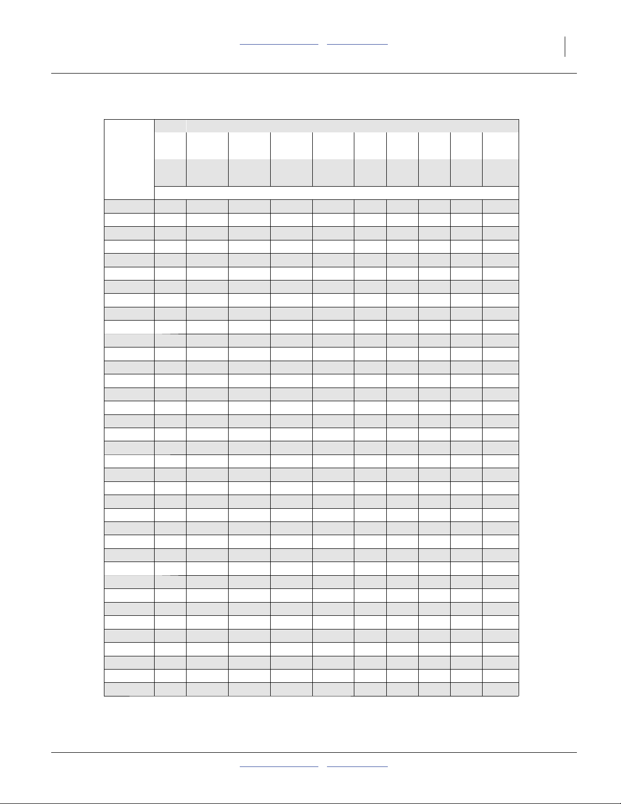
Spacing (U.S. Customary units, page 1 of 2)
Row Spacings
Twin Row Twin Row Twin Row Twin Row
30in 36in 38in 40in
Plant 10in 15in 20in 22in 30in 36in 38in 40in
Population Rows Rows Rows Rows Rows Rows Rows Rows
(seeds/acre)
14 000
15 000
16 000
17 000
18 000
19 000
20 000
21 000
22 000
23 000
24 000
25 000
26 000
27 000
28 000
29 000
30 000
31 000
32 000
33 000
34 000
35 000
36 000
37 000
38 000
39 000
40 000
41 000
42 000
43 000
44 000
45 000
46 000
47 000
48 000
49 000
50 000
44.8 29.9 24.9 23.6 22.4 20.4 14.9 12.4 11.8 11.2
41.8 27.9 23.2 22.0 20.9 19.0 13.9 11.6 11.0 10.5
39.2 26.1 21.8 20.6 19.6 17.8 13.1 10.9 10.3 9.8
36.9 24.6 20.5 19.4 18.4 16.8 12.3 10.2 9.7 9.2
34.8 23.2 19.4 18.3 17.4 15.8 11.6 9.7 9.2 8.7
33.0 22.0 18.3 17.4 16.5 15.0 11.0 9.2 8.7 8.3
31.4 20.9 17.4 16.5 15.7 14.3 10.5 8.7 8.3 7.8
29.9 19.9 16.6 15.7 14.9 13.6 10.0 8.3 7.9 7.5
28.5 19.0 15.8 15.0 14.3 13.0 9.5 7.9 7.5 7.1
27.3 18.2 15.2 14.4 13.6 12.4 9.1 7.6 7.2 6.8
26.1 17.4 14.5 13.8 13.1 11.9 8.7 7.3 6.9 6.5
25.1 16.7 13.9 13.2 12.5 11.4 8.4 7.0 6.6 6.3
24.1 16.1 13.4 12.7 12.1 11.0 8.0 6.7 6.3 6.0
23.2 15.5 12.9 12.2 11.6 10.6 7.7 6.5 6.1 5.8
22.4 14.9 12.4 11.8 11.2 10.2 7.5 6.2 5.9 5.6
21.6 14.4 12.0 11.4 10.8 9.8 7.2 6.0 5.7 5.4
20.9 13.9 11.6 11.0 10.5 9.5 7.0 5.8 5.5 5.2
20.2 13.5 11.2 10.6 10.1 9.2 6.7 5.6 5.3 5.1
19.6 13.1 10.9 10.3 9.8 8.9 6.5 5.4 5.2 4.9
19.0 12.7 10.6 10.0 9.5 8.6 6.3 5.3 5.0 4.8
18.4 12.3 10.2 9.7 9.2 8.4 6.1 5.1 4.9 4.6
17.9 11.9 10.0 9.4 9.0 8.1 6.0 5.0 4.7 4.5
17.4 11.6 9.7 9.2 8.7 7.9 5.8 4.8 4.6 4.4
17.0 11.3 9.4 8.9 8.5 7.7 5.7 4.7 4.5 4.2
16.5 11.0 9.2 8.7 8.3 7.5 5.5 4.6 4.3 4.1
16.1 10.7 8.9 8.5 8.0 7.3 5.4 4.5 4.2 4.0
15.7 10.5 8.7 8.3 7.8 7.1 5.2 4.4 4.1 3.9
15.3 10.2 8.5 8.1 7.6 7.0 5.1 4.2 4.0 3.8
14.9 10.0 8.3 7.9 7.5 6.8 5.0 4.1 3.9 3.7
14.6 9.7 8.1 7.7 7.3 6.6 4.9 4.1 3.8 3.6
14.3 9.5 7.9 7.5 7.1 6.5 4.8 4.0 3.8 3.6
13.9 9.3 7.7 7.3 7.0 6.3 4.6 3.9 3.7 3.5
13.6 9.1 7.6 7.2 6.8 6.2 4.5 3.8 3.6 3.4
13.3 8.9 7.4 7.0 6.7 6.1 4.4 3.7 3.5 3.3
13.1 8.7 7.3 6.9 6.5 5.9 4.4 3.6 3.4 3.3
12.8 8.5 7.1 6.7 6.4 5.8 4.3 3.6 3.4 3.2
12.5 8.4 7.0 6.6 6.3 5.7 4.2 3.5 3.3 3.1
Seed Spacing (inches)
32320A
2012-02-29 Table of Contents Metric Charts 401-626B
Page 6
4 YP2425A Table of Contents Metric Charts Great Plains Manufacturing, Inc.
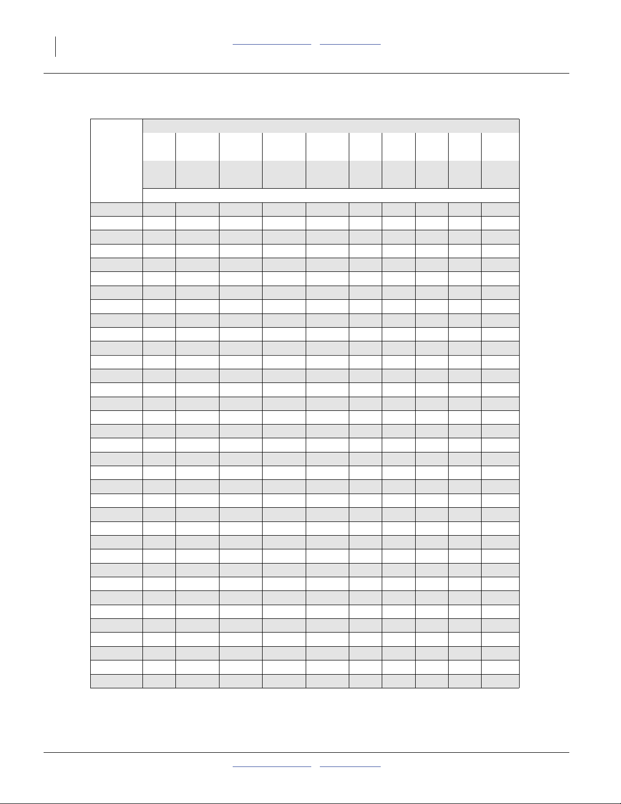
Spacing (U.S. Customary units, page 2 of 2)
Row Spacings
Twin Row Twin Row Twin Row Twin Row
30in 36in 38in 40in
Plant 10in 15in 20in 22in 30in 36in 38in 40in
Population Rows Rows Rows Rows Rows Rows Rows Rows
(seeds/acre) Seed Spacing (inches)
50 000 12.5 8.4 7.0 6.6 6.3 5.7 4.2 3.5 3.3 3.1
55 000 11.4 7.6 6.3 6.0 5.7 5.2 3.8 3.2 3.0 2.9
60 000 10.5 7.0 5.8 5.5 5.2 4.8 3.5 2.9 2.8 2.6
65 000 9.7 6.4 5.4 5.1 4.8 4.4 3.2 2.7 2.5 2.4
70 000 9.0 6.0 5.0 4.7 4.5 4.1 3.0 2.5 2.4 2.2
75 000 8.4 5.6 4.6 4.4 4.2 3.8 2.8 2.3 2.2 2.1
80 000 7.8 5.2 4.4 4.1 3.9 3.6 2.6 2.2 2.1 2.0
85 000 7.4 4.9 4.1 3.9 3.7 3.4 2.5 2.0 1.9 1.8
90 000 7.0 4.6 3.9 3.7 3.5 3.2 2.3 1.9 1.8 1.7
95 000 6.6 4.4 3.7 3.5 3.3 3.0 2.2 1.8 1.7 1.7
100 000 6.3 4.2 3.5 3.3 3.1 2.9 2.1 1.7 1.7 1.6
105 000 6.0 4.0 3.3 3.1 3.0 2.7 2.0 1.7 1.6 1.5
110 000 5.7 3.8 3.2 3.0 2.9 2.6 1.9 1.6 1.5 1.4
115 000 5.5 3.6 3.0 2.9 2.7 2.5 1.8 1.5 1.4 1.4
120 000 5.2 3.5 2.9 2.8 2.6 2.4 1.7 1.5 1.4 1.3
125 000 5.0 3.3 2.8 2.6 2.5 2.3 1.7 1.4 1.3 1.3
130 000 4.8 3.2 2.7 2.5 2.4 2.2 1.6 1.3 1.3 1.2
135 000 4.6 3.1 2.6 2.4 2.3 2.1 1.5 1.3 1.2 1.2
140 000 4.5 3.0 2.5 2.4 2.2 2.0 1.5 1.2 1.2 1.1
145 000 4.3 2.9 2.4 2.3 2.2 2.0 1.4 1.2 1.1 1.1
150 000 4.2 2.8 2.3 2.2 2.1 1.9 1.4 1.2 1.1 1.0
155 000 4.0 2.7 2.2 2.1 2.0 1.8 1.3 1.1 1.1 1.0
160 000 3.9 2.6 2.2 2.1 2.0 1.8 1.3 1.1 1.0 1.0
165 000 3.8 2.5 2.1 2.0 1.9 1.7 1.3 1.1 1.0 1.0
170 000 3.7 2.5 2.0 1.9 1.8 1.7 1.2 1.0 1.0 0.9
175 000 3.6 2.4 2.0 1.9 1.8 1.6 1.2 1.0 0.9 0.9
180 000 3.5 2.3 1.9 1.8 1.7 1.6 1.2 1.0 0.9 0.9
185 000 3.4 2.3 1.9 1.8 1.7 1.5 1.1 0.9 0.9 0.8
190 000 3.3 2.2 1.8 1.7 1.7 1.5 1.1 0.9 0.9 0.8
195 000 3.2 2.1 1.8 1.7 1.6 1.5 1.1 0.9 0.8 0.8
200 000 3.1 2.1 1.7 1.7 1.6 1.4 1.0 0.9 0.8 0.8
225 000 2.8 1.9 1.5 1.5 1.4 1.3 0.9 0.8 0.7 0.7
250 000 2.5 1.7 1.4 1.3 1.3 1.1 0.8 0.7 0.7 0.6
275 000 2.3 1.5 1.3 1.2 1.1 1.0 0.8 0.6 0.6 0.6
300 000 2.1 1.4 1.2 1.1 1.0 1.0 0.7 0.6 0.6 0.5
32320B
401-626B Table of Contents Metric Charts 2012-02-29
Page 7
Great Plains Manufacturing, Inc. Table of Contents Metric Charts Rate Setting Overview 5
Air-Pro® Meter Disk Selection
CORN CORN
24 Cell Disk 40 Cell Disk
817-794C Corn Round Large 817-796C Corn Round Large
817-795C Corn Round Small 817-797C Corn Round Small
817-836C Corn Flat Large 817-838C Corn Flat Large
( Sweet Corn plants in Round Corn disks )
Seed Size Recommendations.
Corn Round Large Seeds per Pound
1700 (or fewer)
Unit Weight (or heavier)
47 pounds
Corn Round Small Seeds per Pound
1650 (or more)
Corn Flat Large Seeds per Pound
1650 (or fewer)
Corn Flat Small Seeds per Pound
1650 (or more)
ATTENTION: This Corn is planted with the Corn Round Small Disks!!!!!!
40in Rows
38in Rows
36in Rows
30in Rows
22in Rows
Twin Row 40in
20in Rows
Twin Row 38in
Twin Row 36in
Twin Row 30in
15in Rows
Below 19 400 Population @ 5.5 MPH 24 Cell Disk
Above 19 400 Population @ 5.5 MPH 40 Cell Disk
Below 20 500 Population @ 5.5 MPH 24 Cell Disk
Above 20 500 Population @ 5.5 MPH 40 Cell Disk
Below 21 600 Population @ 5.5 MPH 24 Cell Disk
Above 21 600 Population @ 5.5 MPH 40 Cell Disk
Below 25 900 Population @ 5.5 MPH 24 Cell Disk
Above 25 900 Population @ 5.5 MPH 40 Cell Disk
Below 35 300 Population @ 5.5 MPH 24 Cell Disk
Above 35 300 Population @ 5.5 MPH 40 Cell Disk
Below 38 900 Population @ 5.5 MPH 24 Cell Disk
Above 38 900 Population @ 5.5 MPH 40 Cell Disk
Below 40 900 Population @ 5.5 MPH 24 Cell Disk
Above 40 900 Population @ 5.5 MPH 40 Cell Disk
Below 43 200 Population @ 5.5 MPH 24 Cell Disk
Above 43 200 Population @ 5.5 MPH 40 Cell Disk
Below 51 800 Population @ 5.5 MPH 24 Cell Disk
Above 51 800 Population @ 5.5 MPH 40 Cell Disk
Unit Weight (or lighter)
48.5 pounds
Unit Weight (or lighter)
48.5 pounds
Unit Weight (or lighter)
48.5 pounds
(Recommended)
COTTON
60 Cell Disk
817-857C
Seed Size Recommendations.
This disk should plant all seed sizes and row spacings for Cotton.
32228A
2012-02-29 Table of Contents Metric Charts 401-626B
Page 8
6 YP2425A Table of Contents Metric Charts Great Plains Manufacturing, Inc.
AIR-PRO
MILO / PELLETIZED SUGAR BEET MILO / PELLETIZED SUGAR BEET
65 Cell Disk 130 Cell Disk
817-849C 817-800C
Seed Size Recommendations.
These disks should plant all seed sizes of Milo and Pelletized Sugar Beets.
(Recommended)
40in Rows Below 48 300 Population @ 6 MPH 65 Cell Disk
Above 48 300 Population @ 6 MPH 130 Cell Disk
38in Rows Below 50 800 Population @ 6 MPH 65 Cell Disk
Above 50 800 Population @ 6 MPH 130 Cell Disk
36in Rows Below 53 600 Population @ 6 MPH 65 Cell Disk
Above 53 600 Population @ 6 MPH 130 Cell Disk
30in Rows Below 64 300 Population @ 6 MPH 65 Cell Disk
Above 64 300 Population @ 6 MPH 130 Cell Disk
22in Rows Below 87 700 Population @ 6 MPH 65 Cell Disk
Above 87 700 Population @ 6 MPH 130 Cell Disk
Twin Row 40in Below 96 500 Population @ 6 MPH 65 Cell Disk
20in Rows Above 96 500 Population @ 6 MPH 130 Cell Disk
Twin Row 38in Below 101 600 Population @ 6 MPH 65 Cell Disk
Above 101 600 Population @ 6 MPH 130 Cell Disk
Twin Row 36in Below 107 200 Population @ 6 MPH 65 Cell Disk
Above 107 200 Population @ 6 MPH 130 Cell Disk
Twin Row 30in Below 128 700 Population @ 6 MPH 65 Cell Disk
15in Rows Above 128 700 Population @ 6 MPH 130 Cell Disk
10in Rows Below 193 000 Population @ 6 MPH 65 Cell Disk
Above 193 000 Population @ 6 MPH 130 Cell Disk
SOYBEAN SOYBEAN
84 Cell Disk 168 Cell Disk
817-798C 403-551D
Seed Size Recommendations.
Small edible beans (navy, black jack, black eye peas, etc) will plant with this disk also.
40in Rows Below 76 900 Population @ 6 MPH 84 Cell Disk
38in Rows Below 81 000 Population @ 6 MPH 84 Cell Disk
36in Rows Below 85 500 Population @ 6 MPH 84 Cell Disk
30in Rows Below 102 500 Population @ 6 MPH 84 Cell Disk
22in Rows Below 139 800 Population @ 6 MPH 84 Cell Disk
Twin Row 40in Below 153 800 Population @ 6 MPH 84 Cell Disk
20in Rows Above 153 800 Population @ 6 MPH 168 Cell Disk
Twin Row 38in Below 161 900 Population @ 6 MPH 84 Cell Disk
Twin Row 36in Below 170 900 Population @ 6 MPH 84 Cell Disk
Twin Row 30in Below 205 100 Population @ 6 MPH 84 Cell Disk
15in Rows Above 205 100 Population @ 6 MPH 168 Cell Disk
10in Rows Below 307 700 Population @ 6 MPH 84 Cell Disk
These disks should plant all seed sizes of Soybeans.
(Recommended)
Above 76 900 Population @ 6 MPH 168 Cell Disk
Above 81 000 Population @ 6 MPH 168 Cell Disk
Above 85 500 Population @ 6 MPH 168 Cell Disk
Above 102 500 Population @ 6 MPH 168 Cell Disk
Above 139 800 Population @ 6 MPH 168 Cell Disk
Above 161 900 Population @ 6 MPH 168 Cell Disk
Above 170 900 Population @ 6 MPH 168 Cell Disk
Above 307 700 Population @ 6 MPH 168 Cell Disk
32228B
401-626B Table of Contents Metric Charts 2012-02-29
Page 9

Great Plains Manufacturing, Inc. Table of Contents Metric Charts Rate Setting Overview 7
817-851C SUNFLOWER OIL LARGE
Volumetric No.1 84 Cell Disk
817-867C
Air Meter Blank Disk
817-841C
AIR-PRO
SUNFLOWER
24 Cell Disk
This disk should plant all seed sizes of popcorn.
Seed Size Recommendations.
Sunflower Oil Large Seeds per Pound
2's - most 3's 8500 (or fewer)
And a few of the larger 4's (or fewer)
Available for:
Wheat
These disks are used in (Off Row Meters) when changing from 15" to 30" Rows.
Twin Row 30" to 30" Rows. Twin Row 40" to 40" Rows. (etc)
32228C
2012-02-29 Table of Contents Metric Charts 401-626B
Page 10
8 YP2425A Table of Contents Metric Charts Great Plains Manufacturing, Inc.
(y)
Meter Pressurization
Refer to the Operator Manual for the procedure for fine
tuning meter pressurization.
Start with pressures from below and on page 9, which
are based on crop, and for corn, seed shape and density.
Note: These are suggested initial (starting) pressures.
Use the seed monitor console to adjust them up or
down per the procedure in the YP2425A Operator
Manual.
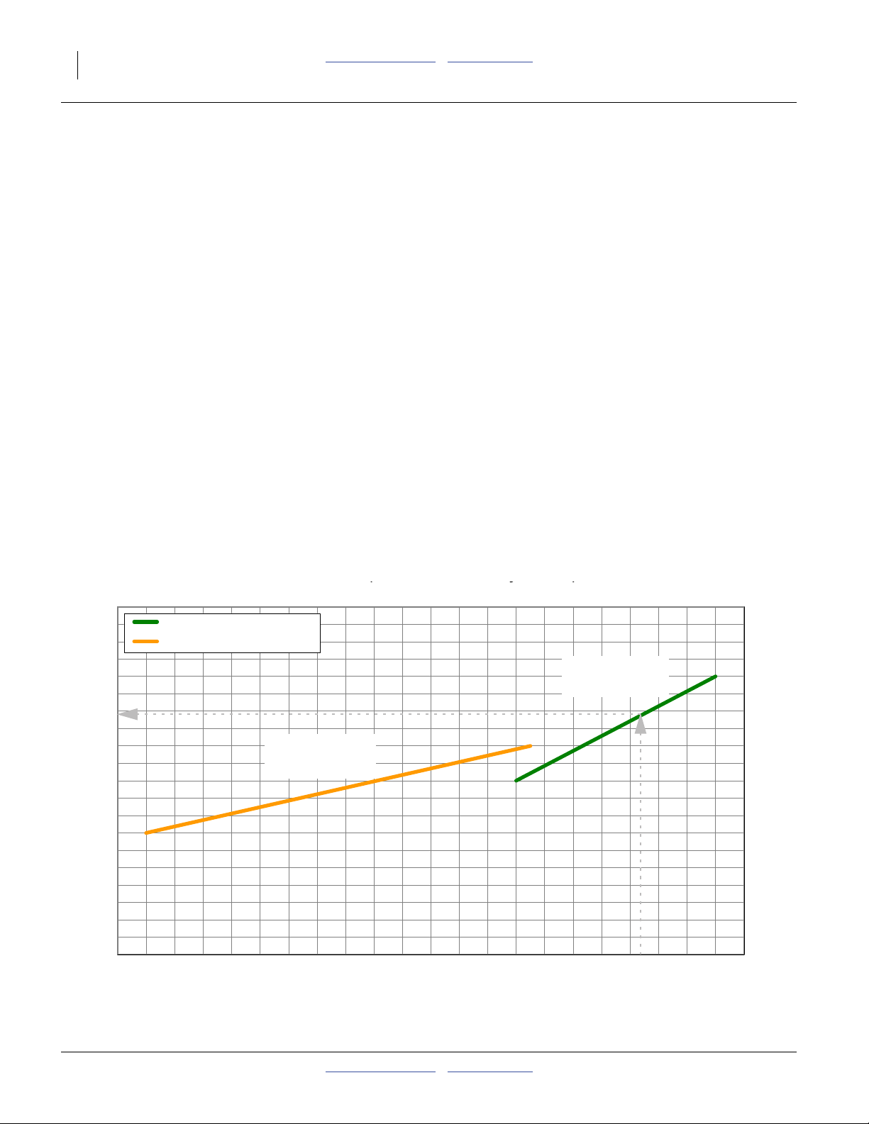
Corn: Reading a Pressure Chart (below, next page)
1. Pick the chart based on seed shape (flat, round).
Example: large round corn
2. Pick a line based on seed size (large, small).
Example: the right line below
3. Find the seed density on the bottom scale.
Example: 1260 seeds/pound
4. Read the suggested starting pressure on the left
scale, where the line (example shown as dotted
gray) intersects the density.
Example: 3.4 inches of water
Initial seed inlet Shutter for corn is: 3
Initial Meter Pressurization: Cotton
1.5 inches of water (any seed density)
Initial seed inlet Shutter: 2
Initial Meter Pressurization: Milo
1.5 inches of water (all disk, any seed density)
Initial seed inlet Shutter: 1
Initial Meter Pressurization: Soybeans
2.0 inches of water (84 cell disk, any seed density)
3.0 inches of water (168 cell disk, any seed density)
Initial seed inlet Shutter: 2
Initial Meter Pressurization: Sunflower
Disk: 817-851C SUNFLOWER OIL LARGE
8500 seeds/pound (or fewer):
8500 - 7000 s/lb 1.25 inches of water
7000 - 5500 s/lb 1.75 inches of water
5500 s/lb and fewer 2.25 inches of water
Adjust pressure as needed for desired population.
Initial seed inlet Shutter: 2
Meter Pressure (in/water)
Meter Pressurization in inches of Water
4.5
3.5
2.5
1.5
0.5
5
4
3
2
1
0
3100
25.8
Initial Meter Pressurization: Round Corn
Linear (Round Corn Large)
Linear (Round Corn Small)
Example
817-795C & 817-797C
Round Corn-Small
27002900
29.627.6
Pressure/Seed Comparison
Disks
23002500
2100
150017001900
Disks
817-794C & 817-796C
Round Corn-Large
53.347.142.138.134.832.0
Example
11001300
72.761.5
900
88.9
5
4.5
4
3.5
3
2.5
2
1.5
1
0.5
0
Meter Pressurization in inches of Water
Meter Pressure (in/water)
Seeds Per Pound
Unit Weight (80K)
401-626B Table of Contents Metric Charts 2012-02-29
29725
Page 11
Great Plains Manufacturing, Inc. Table of Contents Metric Charts Rate Setting Overview 9
(y)
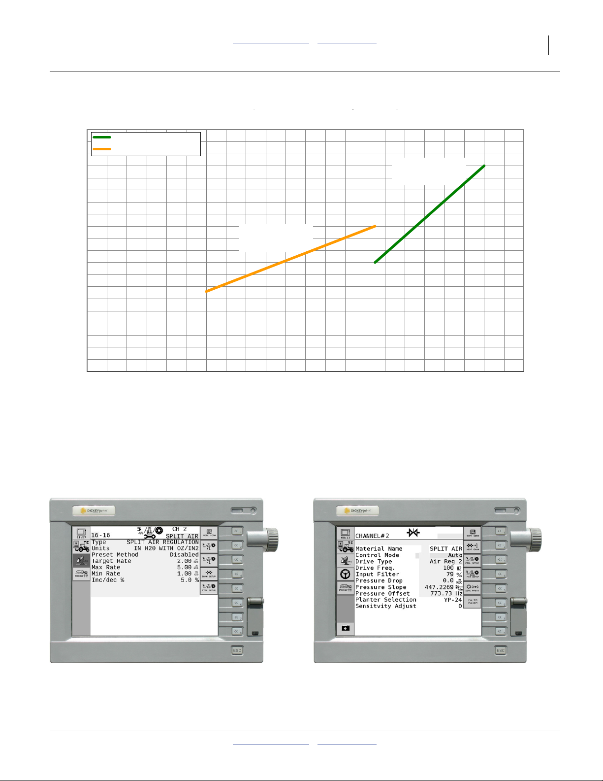
Initial Meter Pressurization: Flat Corn
Pressure/Seed Comparison
4.5
3.5
5
Linear (Flat Corn Large)
Linear (Flat Corn Small)
Disks
4
817-836C & 817-838C
Flat Corn-Large
5
4.5
4
3.5
Meter Pressurization in inches of Water
Meter Pressure (in/water)
Meter Pressure (in/water)
3
2.5
2
1.5
1
Disks
817-795C & 817-797C
Flat Corn-Small
Meter Pressurization in inches of Water
0.5
0
3100
2900
230025002700
2100
38.134.832.029.627.625.8
Seeds Per Pound
Unit Weight (80K)
42.1
47.1
53.3
Factory Default Air Control Channel Screens
Material 16 Setup Control Channel 2 Setup
61.5
3
2.5
2
1.5
1
0.5
0
90011001300150017001900
88.972.7
29726
29753
2012-02-29 Table of Contents Metric Charts 401-626B
29794
Page 12
10 YP2425A Table of Contents Metric Charts Great Plains Manufacturing, Inc.
Checking Planting Rate
Singulated seed charts are based on cleaned and sized
seed singulated with the recommended disk. Extreme
seed size variations and foreign material can affect the
planting rate.
Any material difference between chart and field rates
implies a mechanical malfunction, a planter setup error
or extremely worn planter components. You can verify
your setup and planter performance by measuring seed
placement and spacing over a relatively short distance.
The columns to the right provide example data for a rate
check, in U.S. customary units and a similar example
metric units.
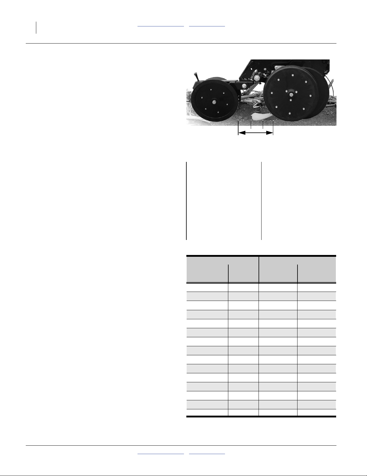
Checking Singulated Rates
1. Determine the sample distance to check. Find your
row spacing in the table at right.
2. Note the number of rows to sample. Adjust the
planting depth to a shallow setting on one or two
outside rows (per table). Tie up the press wheel
arms with wire or bungee to prevent furrow closure.
3. For populations above 100 000 seeds/acre, use a
sample size of 1/1000th acre.
For populations below 100 000 seeds/acre, use a
sample size of 1/200th acre.
4. Configure the planter for the chart rate, either using
the chart settings for sprockets, or, with hydraulic
drive, selecting the rate on the seed monitor.
Figure 3
Furrow Check
US Example:
Planter: YP2425A-2430
Crop: Soybeans
Density: 3000 seeds/lb
Seed Disk: 817-798C
Target Population:
123,000 seeds/acre
Maximum Planting Speed:
5 mph
Chart Seed Spacing:
1.7 inches
Metric Example:
Planter: YP2425A-2470
Crop: Soybeans
Density: 6614 seeds/kg
Seed Disk: 817-798C
Target Population:
438 000 seeds/hectare
Maximum Planting Speed:
5 kph
Chart Seed Spacing:
3.2 cm
Rate check data is from sheet “Check” in:
Rows to Sample Length of Sample Run
Row Row 1/1000th 1/200th
Spacing* Count Acre Acre
7.5in Single 4 17ft 5in
8in Single 4 16ft 4in
9.5in Single 4 13ft 9in
10in Single 2 26ft 2in
15in Single 2 17ft 5in 87ft 1in
20in Single 1 26ft 2in 130ft 8in
22in Single 1 23ft 9in
118ft 10in
30in Single 1 17ft 5in 87ft 1in
36in Single 1 14ft 6in 72ft 7in
38in Single 1 13ft 9in 68ft 9in
40in Single 1 13ft 1in 65ft 4in
30in Twin 1 pair 17ft 5in 87ft 1in
36in Twin 1 pair 14ft 6in 72ft 7in
38in Twin 1 pair 13ft 9in 68ft 9in
40in Twin 1 pair 13ft 1in 65ft 4in
* Not all spacings may be offered on implements
covered by this manual.
29247
31442
401-626B Table of Contents Metric Charts 2012-02-29
Page 13

Great Plains Manufacturing, Inc. Table of Contents Metric Charts Rate Setting Overview 11
5. Plant at the desired planting speed for slightly more
than the computed sample run length.
6. Measure off the sample distance, balanced in
between where seeding started and stopped.
7. Count the number of seeds over the distance
measured. Also note the consistency of the seed
spacing.
8. Compute the rate for a full acre or hectare.
For a 1/1000th sample, multiply the counted seeds
by 1000.
For a 1/200th sample, multiply the counted seeds by
200.
9. If the field and chart rates vary by more than a few
percent, re-check planter setup, including meter disk
or cell count, air system, hydraulic drive setup, chain
slack, etc. If seed spacing is irregular, this suggests
a seed delivery problem, and not a rate setup
problem.
10. While planting, pay attention to the seed monitor. In
addition to confirming the single-row furrow check, it
will also provide field rate data on all the other rows,
and alert you to any irregularities or stoppages.
USc Example:
Sample size:
1/1000th ac
Plant for approximately:
25 feet
Measure the central:
17 feet 5 inches
USc Example:
Seeds counted:
121
Computed for full acre:
121 × 1000 = 121,000
This differs from chart by:
1.8%
Metric Example:
Sample size:
1/200th ha
Plant for approximately:
20 meters
Measure the central:
14.29 meters
Metric Example:
Seeds counted:
300
Computed for full hectare:
300 × 1000 = 300,000
This differs from chart by:
0.6%
2012-02-29 Table of Contents Metric Charts 401-626B
Page 14
12 YP2425A Table of Contents Metric Charts Great Plains Manufacturing, Inc.
Planting Rate
Singulated planting employs the seed monitor in
“PLANTER CONTROL” mode.
Hydraulic Drive Meter Rate
Hydraulic drive meter rate is set directly on the seed
monitor in the tractor. Consult the monitor manual for
detailed instructions, which may vary slightly over time
with firmware updates to the monitor system.
Enter/update your planter configuration (width/row-count,
single-row/twin, disk cell count, etc.). Once entered,
specify the population directly in seeds/acre or seeds/ha.
Enter meter RPM limits for your disk (pages 13-20).
Note: For consistent results, and least meter wear, do not
exceed the recommended ground speed.
For step 1 through step 4, any needed data not provided
in this manual can be found in one or more of:
DICKEY-john
®
Quick Start Guide
Planter Operator Manual
Refer to the DICKEY-john®IntelliAg® Planter/Drill
Control Operator’s Manual for details on setup item.
Note: The monitor must be in User Level 2 to change
some of these parameters.
1. For a crop not previously planted with this planter,
create a “Material Name” for the crop. Selecting a
named material is a required step in later screens.
2. Verify, and as needed setup or update the “Material”
record for the singulated seed to be planted.
The table at right lists the parameters that need to be
reviewed or set. <angle bracket> values are your
choice/preference when not from meter rpm chart.
3. Verify, and as necessary setup or update the
“Channel” assigned to the planter’s hydraulic drive.
If the monitor resets to defaults, Gear Ratio may be
incorrect.
Count rows individually for “# Seed Rows”. A twin
pair (if both openers are in use) counts as 2 rows.
“Channel Width” is swath.
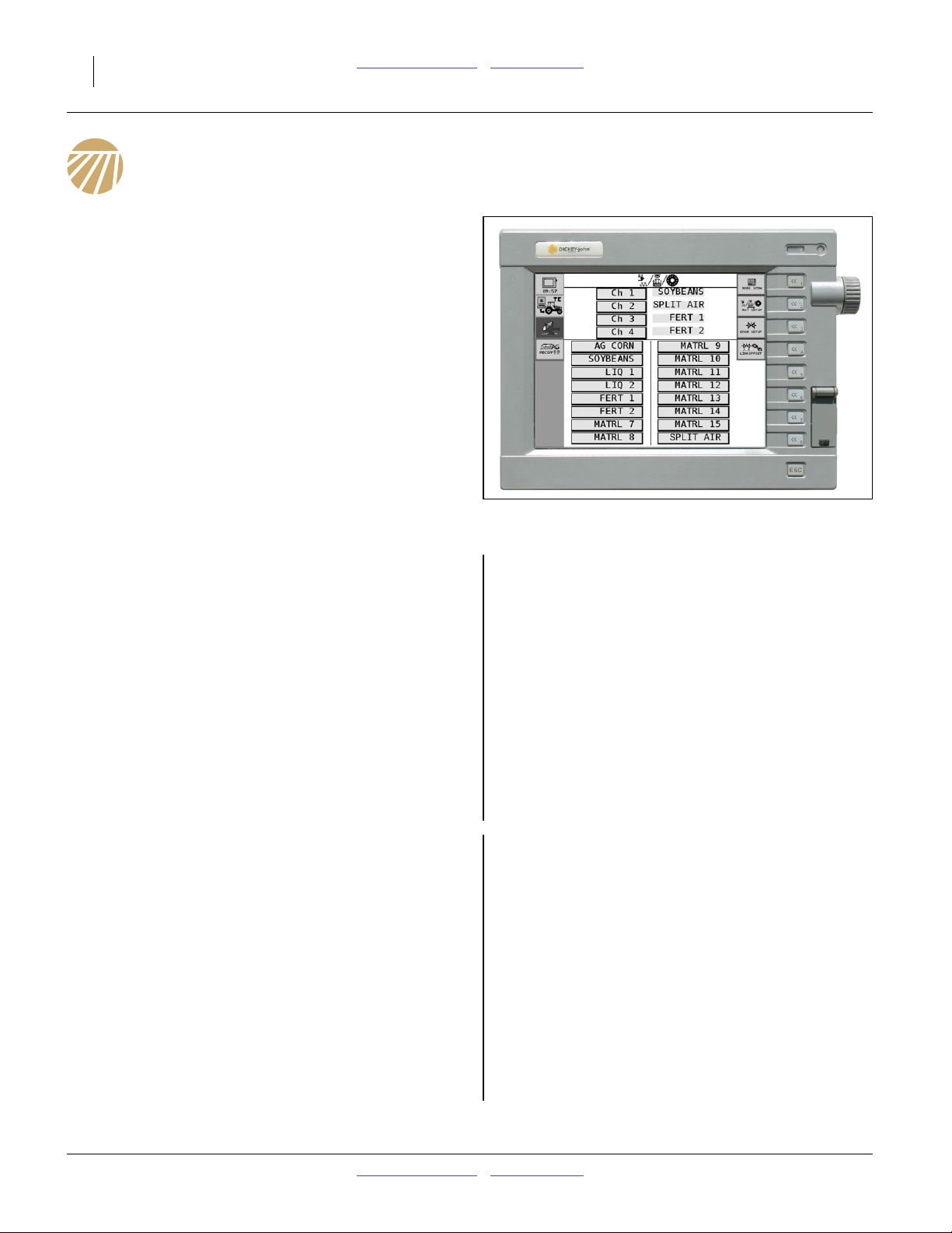
4. In the Material Library screen, makes sure that the
Material (SOYBEANS in our example) is assigned to
the Channel (CH 1 in our example) which controls
the planter’s hydraulic drive.
5. Perform a Valve Calibration for the control channel.
6. Switch the seed monitor from Setup/Configuration
mode to Operate mode. Load seed. Move the planter
to the field.
Figure 4
Typical Control Setup Screen
Material Data Required
Material Name <crop name, such as “SOYBEANS”>
Channel “CH 1”
Type “PLANTER CONTROL”
Preset Method “Disabled” unless populations vary
Target Rate <your election>
Max Rate <110% of Target> is suggested
Min Rate <90% of Target> is suggested
Inc/Dec “1.0%” is suggested
Seeds Per Rev <seed disk cell count>
Disc Low Limit <rpm from seed rate chart>
Disc High Limit <rpm from seed rate chart>
High Pop Alarm <“20%”> is suggested
Low Pop Alarm <“20%”> is suggested
Prod Level Alarm 0
Channel Data Required
CHANNEL 1 (must be channel specified above)
Type “PLANTER CONTROL”
Material Name (must be material name specified above)
Control Mode Auto
Drive Type PWM 1
Drive Freq. 100 Hz
Input Filter 50%
Gear Ratio 1.900
Sensor Constant 360
# Seed Rows <based on planter model/row setup>
Channel Width <based on planter model/row setup>
Precharge Time 0
Delay Time 0
Flush Enable Disabled
29750
401-626B Table of Contents Metric Charts 2012-02-29
Page 15
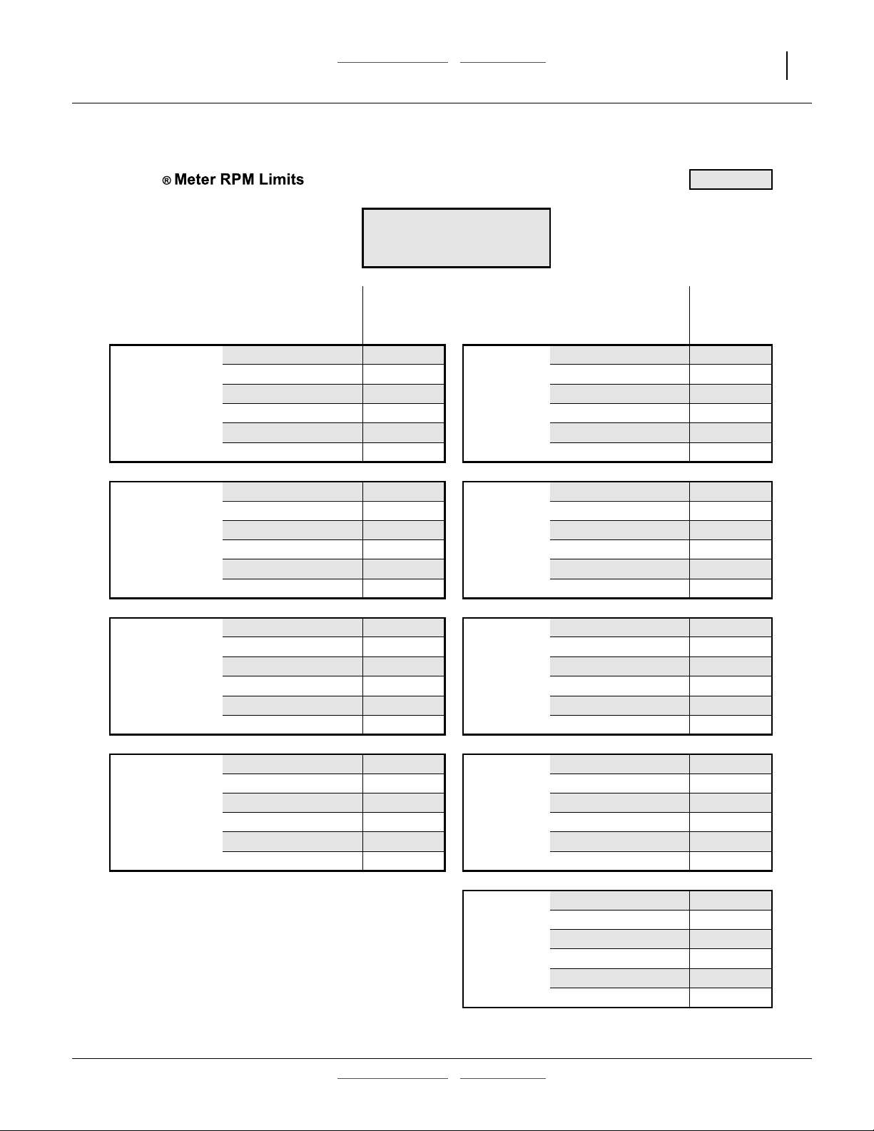
Great Plains Manufacturing, Inc. Table of Contents Metric Charts Planting Rate 13
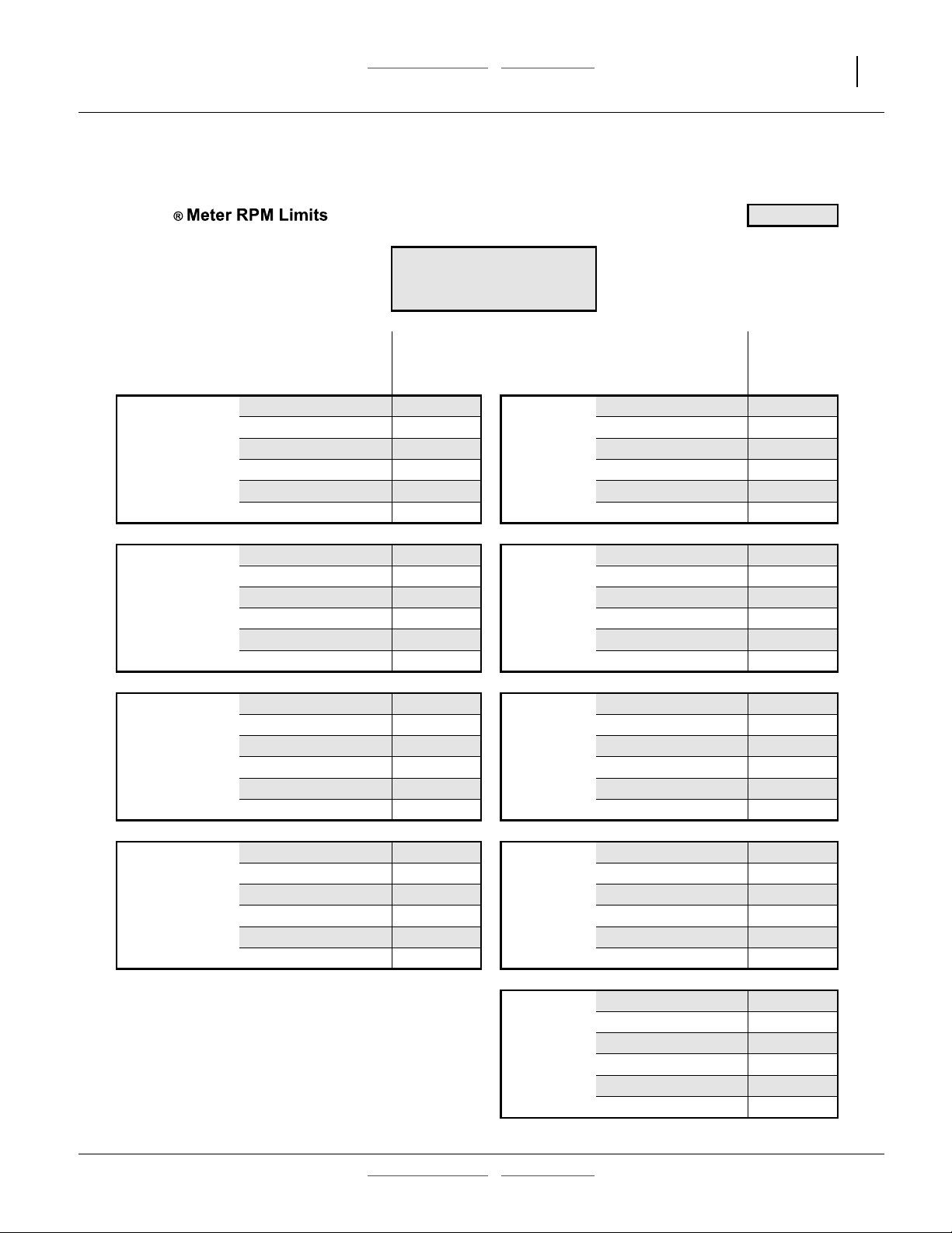
Air-Pro
Meter RPM Limit Charts
Initial Seed Inlet Shutter Setting: 3
CORN
24 Cell Disk
Planting Maximum Minimum Planting Maximum Minimum
Speed Population Population Speed Population Population
(mph) (seeds/acre) (seeds/acre) (mph) (seeds/acre) (seeds/acre)
Twin Row 30in 4.0 71 280 23 760 22in Rows 4.0 48 600 16 200
15in Rows 4.5 63 360 21 120 Max Min 4.5 43 200 14 400
Max Min 5.0 57 024 19 008 rpm rpm 5.0 38 880 12 960
rpm rpm 5.5 51 840 17 280 30 10 5.5 35 345 11 782
30 10 6.0 47 520 15 840 6.0 32 400 10 800
6.5 43 865 14 622 6.5 29 908 9 969
817-794C Round Corn Large
817-795C Round Corn Small
817-836C Flat Corn Large
Twin Row 36in 4.0 59 400 19 800 30in Rows 4.0 35 640 11 880
Max Min 4.5 52 800 17 600 Max Min 4.5 31 680 10 560
rpm rpm 5.0 47 520 15 840 rpm rpm 5.0 28 512 9 504
30 10 5.5 43 200 14 400 30 10 5.5 25 920 8 640
6.0 39 600 13 200 6.0 23 760 7 920
6.5 36 554 12 185 6.5 21 932 7 311
Twin Row 38in 4.0 56 274 18 758 36in Rows 4.0 29 700 9 900
Max Min 4.5 50 021 16 674 Max Min 4.5 26 400 8 800
rpm rpm 5.0 45 019 15 006 rpm rpm 5.0 23 760 7 920
30 10 5.5 40 926 13 642 30 10 5.5 21 600 7 200
6.0 37 516 12 505 6.0 19 800 6 600
6.5 34 630 11 543 6.5 18 277 6 092
Twin Row 40in 4.0 53 460 17 820 38in Rows 4.0 28 137 9 379
20in Rows 4.5 47 520 15 840 Max Min 4.5 25 011 8 337
Max Min 5.0 42 768 14 256 rpm rpm 5.0 22 509 7 503
rpm rpm 5.5 38 880 12 960 30 10 5.5 20 463 6 821
30 10 6.0 35 640 11 880 6.0 18 758 6 253
6.5 32 898 10 966 6.5 17 315 5 772
40in Rows 4.0 26 730 8 910
Max Min 4.5 23 760 7 920
rpm rpm 5.0 21 384 7 128
30 10 5.5 19 440 6 480
6.0 17 820 5 940
6.5 16 449 5 483
29652A
2012-02-29 Table of Contents Metric Charts 401-626B
Page 16
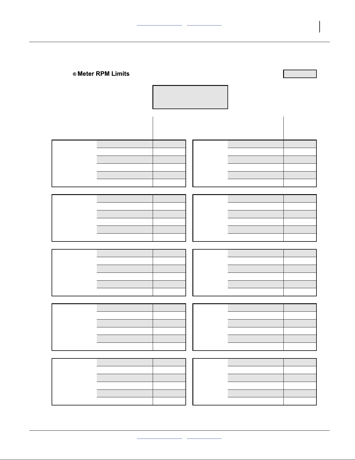
14 YP2425A Table of Contents Metric Charts Great Plains Manufacturing, Inc.
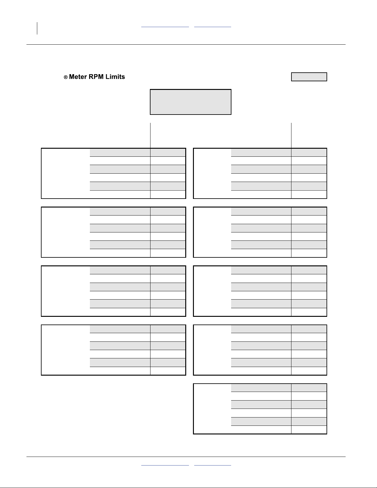
Air-Pro
Initial Seed Inlet Shutter Setting: 3
CORN
40 Cell Disk
Planting Maximum Minimum Planting Maximum Minimum
Speed Population Population Speed Population Population
(mph) (seeds/acre) (seeds/acre) (mph) (seeds/acre) (seeds/acre)
Twin Row 30in 4.0 118 800 39 600 22in Rows 4.0 81 000 27 000
15in Rows 4.5 105 600 35 200 Max Min 4.5 72 000 24 000
Max Min 5.0 95 040 31 680 rpm rpm 5.0 64 800 21 600
rpm rpm 5.5 86 400 28 800 30 10 5.5 58 909 19 636
30 10 6.0 79 200 26 400 6.0 54 000 18 000
6.5 73 108 24 369 6.5 49 846 16 615
817-796C Round Corn Large
817-797C Round Corn Small
817-838C Flat Corn Large
Twin Row 36in 4.0 99 000 33 000 30in Rows 4.0 59 400 19 800
Max Min 4.5 88 000 29 333 Max Min 4.5 52 800 17 600
rpm rpm 5.0 79 200 26 400 rpm rpm 5.0 47 520 15 840
30 10 5.5 72 000 24 000 30 10 5.5 43 200 14 400
6.0 66 000 22 000 6.0 39 600 13 200
6.5 60 923 20 308 6.5 36 554 12 185
Twin Row 38in 4.0 93 789 31 263 36in Rows 4.0 49 500 16 500
Max Min 4.5 83 368 27 789 Max Min 4.5 44 000 14 667
rpm rpm 5.0 75 032 25 011 rpm rpm 5.0 39 600 13 200
30 10 5.5 68 211 22 737 30 10 5.5 36 000 12 000
6.0 62 526 20 842 6.0 33 000 11 000
6.5 57 717 19 239 6.5 30 462 10 154
Twin Row 40in 4.0 89 100 29 700 38in Rows 4.0 46 895 15 632
20in Rows 4.5 79 200 26 400 Max Min 4.5 41 684 13 895
Max Min 5.0 71 280 23 760 rpm rpm 5.0 37 516 12 505
rpm rpm 5.5 64 800 21 600 30 10 5.5 34 105 11 368
30 10 6.0 59 400 19 800 6.0 31 263 10 421
6.5 54 831 18 277 6.5 28 858 9 619
40in Rows 4.0 44 550 14 850
Max Min 4.5 39 600 13 200
rpm rpm 5.0 35 640 11 880
30 10 5.5 32 400 10 800
6.0 29 700 9 900
6.5 27 415 9 138
29652B
401-626B Table of Contents Metric Charts 2012-02-29
Page 17
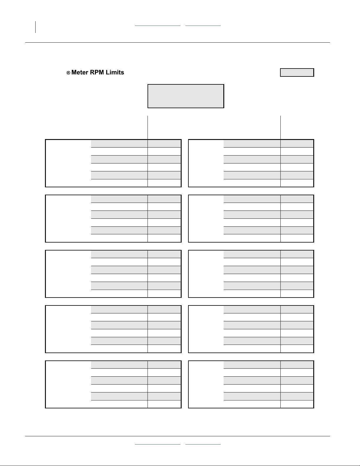
Great Plains Manufacturing, Inc. Table of Contents Metric Charts Planting Rate 15
Air-Pro
Initial Seed Inlet Shutter Setting: 2
COTTON
60 Cell Disk
817-857C Cotton
Planting Maximum Minimum Planting Maximum Minimum
Speed Population Population Speed Population Population
(mph) (seeds/acre) (seeds/acre) (mph) (seeds/acre) (seeds/acre)
Twin Row 30in 4.0 190 080 29 700 22in Rows 4.0 129 600 20 250
15in Rows 4.5 168 960 26 400 Max Min 4.5 115 200 18 000
Max Min 5.0 152 064 23 760 rpm rpm 5.0 103 680 16 200
rpm rpm 5.5 138 240 21 600 30 10 5.5 94 255 14 727
30 10 6.0 126 720 19 800 6.0 86 400 13 500
6.5 116 972 18 277 6.5 79 754 12 462
Twin Row 36in 4.0 158 400 24 750 30in Rows 4.0 95 040 14 850
Max Min 4.5 140 800 22 000 Max Min 4.5 84 480 13 200
rpm rpm 5.0 126 720 19 800 rpm rpm 5.0 76 032 11 880
30 10 5.5 115 200 18 000 30 10 5.5 69 120 10 800
6.0 105 600 16 500 6.0 63 360 9 900
6.5 97 477 15 231 6.5 58 486 9 138
Twin Row 38in 4.0 150 063 23 447 36in Rows 4.0 79 200 12 375
Max Min 4.5 133 389 20 842 Max Min 4.5 70 400 11 000
rpm rpm 5.0 120 051 18 758 rpm rpm 5.0 63 360 9 900
30 10 5.5 109 137 17 053 30 10 5.5 57 600 9 000
6.0 100 042 15 632 6.0 52 800 8 250
6.5 92 347 14 429 6.5 48 738 7 615
Twin Row 40in 4.0 142 560 22 275 38in Rows 4.0 75 032 11 724
20in Rows 4.5 126 720 19 800 Max Min 4.5 66 695 10 421
Max Min 5.0 114 048 17 820 rpm rpm 5.0 60 025 9 379
rpm rpm 5.5 103 680 16 200 30 10 5.5 54 568 8 526
30 10 6.0 95 040 14 850 6.0 50 021 7 816
6.5 87 729 13 708 6.5 46 173 7 215
40in Rows 4.0 71 280 11 138
Max Min 4.5 63 360 9 900
rpm rpm 5.0 57 024 8 910
30 10 5.5 51 840 8 100
6.0 47 520 7 425
6.5 43 865 6 854
29652C
2012-02-29 Table of Contents Metric Charts 401-626B
Page 18

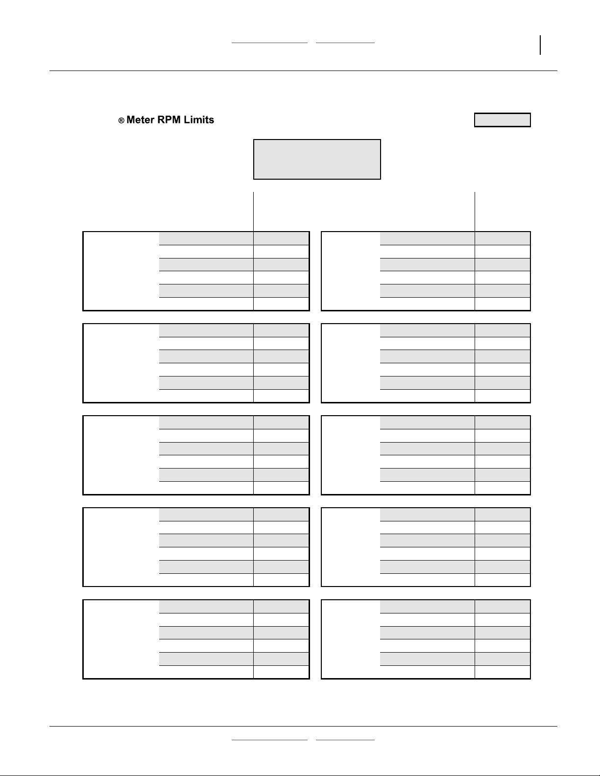
16 YP2425A Table of Contents Metric Charts Great Plains Manufacturing, Inc.
Air-Pro
Initial Seed Inlet Shutter Setting: 2
MILO
65 Cell Disk
817-849C Milo
Planting Maximum Minimum Planting Maximum Minimum
Speed Population Population Speed Population Population
(mph) (seeds/acre) (seeds/acre) (mph) (seeds/acre) (seeds/acre)
10in Rows 4.0 289 575 48 263 22in Rows 4.0 131 625 21 938
Max Min 4.5 257 400 42 900 Max Min 4.5 117 000 19 500
rpm rpm 5.0 231 660 38 610 rpm rpm 5.0 105 300 17 550
30 5 5.5 210 600 35 100 30 5 5.5 95 727 15 955
6.0 193 050 32 175 6.0 87 750 14 625
6.5 178 200 29 700 6.5 81 000 13 500
Twin Row 30in 4.0 193 050 32 175 30in Rows 4.0 96 525 16 088
15in Rows 4.5 171 600 28 600 Max Min 4.5 85 800 14 300
Max Min 5.0 154 440 25 740 rpm rpm 5.0 77 220 12 870
rpm rpm 5.5 140 400 23 400 30 5 5.5 70 200 11 700
30 5 6.0 128 700 21 450 6.0 64 350 10 725
6.5 118 800 19 800 6.5 59 400 9 900
Twin Row 36in 4.0 160 875 26 813 36in Rows 4.0 80 438 13 406
Max Min 4.5 143 000 23 833 Max Min 4.5 71 500 11 917
rpm rpm 5.0 128 700 21 450 rpm rpm 5.0 64 350 10 725
30 5 5.5 117 000 19 500 30 5 5.5 58 500 9 750
6.0 107 250 17 875 6.0 53 625 8 938
6.5 99 000 16 500 6.5 49 500 8 250
Twin Row 38in 4.0 152 408 25 401 38in Rows 4.0 76 204 12 701
Max Min 4.5 135 474 22 579 Max Min 4.5 67 737 11 289
rpm rpm 5.0 121 926 20 321 rpm rpm 5.0 60 963 10 161
30 5 5.5 110 842 18 474 30 5 5.5 55 421 9 237
6.0 101 605 16 934 6.0 50 803 8 467
6.5 93 789 15 632 6.5 46 895 7 816
Twin Row 40in 4.0 144 788 24 131 40in Rows 4.0 72 394 12 066
20in Rows 4.5 128 700 21 450 Max Min 4.5 64 350 10 725
Max Min 5.0 115 830 19 305 rpm rpm 5.0 57 915 9 653
rpm rpm 5.5 105 300 17 550 30 5 5.5 52 650 8 775
30 5 6.0 96 525 16 088 6.0 48 263 8 044
6.5 89 100 14 850 6.5 44 550 7 425
29652D
401-626B Table of Contents Metric Charts 2012-02-29
Page 19
Great Plains Manufacturing, Inc. Table of Contents Metric Charts Planting Rate 17
Air-Pro
Initial Seed Inlet Shutter Setting: 2
MILO
130 Cell Disk
817-800C Milo
Planting Maximum Minimum Planting Maximum Minimum
Speed Population Population Speed Population Population
(mph) (seeds/acre) (seeds/acre) (mph) (seeds/acre) (seeds/acre)
10in Rows 4.0 579 150 96 525 22in Rows 4.0 263 250 43 875
Max Min 4.5 514 800 85 800 Max Min 4.5 234 000 39 000
rpm rpm 5.0 463 320 77 220 rpm rpm 5.0 210 600 35 100
30 5 5.5 421 200 70 200 30 5 5.5 191 455 31 909
6.0 386 100 64 350 6.0 175 500 29 250
6.5 356 400 59 400 6.5 162 000 27 000
Twin Row 30in 4.0 386 100 64 350 30in Rows 4.0 193 050 32 175
15in Rows 4.5 343 200 57 200 Max Min 4.5 171 600 28 600
Max Min 5.0 308 880 51 480 rpm rpm 5.0 154 440 25 740
rpm rpm 5.5 280 800 46 800 30 5 5.5 140 400 23 400
30 5 6.0 257 400 42 900 6.0 128 700 21 450
6.5 237 600 39 600 6.5 118 800 19 800
Twin Row 36in 4.0 321 750 53 625 36in Rows 4.0 160 875 26 813
Max Min 4.5 286 000 47 667 Max Min 4.5 143 000 23 833
rpm rpm 5.0 257 400 42 900 rpm rpm 5.0 128 700 21 450
30 5 5.5 234 000 39 000 30 5 5.5 117 000 19 500
6.0 214 500 35 750 6.0 107 250 17 875
6.5 198 000 33 000 6.5 99 000 16 500
Twin Row 38in 4.0 304 816 50 803 38in Rows 4.0 152 408 25 401
Max Min 4.5 270 947 45 158 Max Min 4.5 135 474 22 579
rpm rpm 5.0 243 853 40 642 rpm rpm 5.0 121 926 20 321
30 5 5.5 221 684 36 947 30 5 5.5 110 842 18 474
6.0 203 211 33 868 6.0 101 605 16 934
6.5 187 579 31 263 6.5 93 789 15 632
Twin Row 40in 4.0 289 575 48 263 40in Rows 4.0 144 788 24 131
20in Rows 4.5 257 400 42 900 Max Min 4.5 128 700 21 450
Max Min 5.0 231 660 38 610 rpm rpm 5.0 115 830 19 305
rpm rpm 5.5 210 600 35 100 30 5 5.5 105 300 17 550
30 5 6.0 193 050 32 175 6.0 96 525 16 088
6.5 178 200 29 700 6.5 89 100 14 850
29652E
2012-02-29 Table of Contents Metric Charts 401-626B
Page 20
18 YP2425A Table of Contents Metric Charts Great Plains Manufacturing, Inc.
Air-Pro
Initial Seed Inlet Shutter Setting: 2
SOYBEAN
84 Cell Disk
817-798C Soybean
Planting Maximum Minimum Planting Maximum Minimum
Speed Population Population Speed Population Population
(mph) (seeds/acre) (seeds/acre) (mph) (seeds/acre) (seeds/acre)
10in Rows 4.0 461 538 62 370 22in Rows 4.0 209 790 28 350
Max Min 4.5 410 256 55 440 Max Min 4.5 186 480 25 200
rpm rpm 5.0 369 230 49 896 rpm rpm 5.0 167 832 22 680
37 5 5.5 335 664 45 360 37 5 5.5 152 575 20 618
6.0 307 692 41 580 6.0 139 860 18 900
6.5 284 023 38 382 6.5 129 102 17 446
Twin Row 30in 4.0 307 692 41 580 30in Rows 4.0 153 846 20 790
15in Rows 4.5 273 504 36 960 Max Min 4.5 136 752 18 480
Max Min 5.0 246 154 33 264 rpm rpm 5.0 123 077 16 632
rpm rpm 5.5 223 776 30 240 37 5 5.5 111 888 15 120
37 5 6.0 205 128 27 720 6.0 102 564 13 860
6.5 189 349 25 588 6.5 94 674 12 794
Twin Row 36in 4.0 256 410 34 650 36in Rows 4.0 128 205 17 325
Max Min 4.5 227 920 30 800 Max Min 4.5 113 960 15 400
rpm rpm 5.0 205 128 27 720 rpm rpm 5.0 102 564 13 860
37 5 5.5 186 480 25 200 37 5 5.5 93 240 12 600
6.0 170 940 23 100 6.0 85 470 11 550
6.5 157 791 21 323 6.5 78 895 10 662
Twin Row 38in 4.0 242 915 32 826 38in Rows 4.0 121 457 16 413
Max Min 4.5 215 924 29 179 Max Min 4.5 107 962 14 589
rpm rpm 5.0 194 332 26 261 rpm rpm 5.0 97 166 13 131
37 5 5.5 176 665 23 874 37 5 5.5 88 333 11 937
6.0 161 943 21 884 6.0 80 972 10 942
6.5 149 486 20 201 6.5 74 743 10 100
Twin Row 40in 4.0 230 769 31 185 40in Rows 4.0 115 385 15 593
20in Rows 4.5 205 128 27 720 Max Min 4.5 102 564 13 860
Max Min 5.0 184 615 24 948 rpm rpm 5.0 92 308 12 474
rpm rpm 5.5 167 832 22 680 37 5 5.5 83 916 11 340
37 5 6.0 153 846 20 790 6.0 76 923 10 395
6.5 142 012 19 191 6.5 71 006 9 595
29652F
401-626B Table of Contents Metric Charts 2012-02-29
Page 21
Great Plains Manufacturing, Inc. Table of Contents Metric Charts Planting Rate 19
Air-Pro
Initial Seed Inlet Shutter Setting: 2
SOYBEAN
168 Cell Disk
403-551D Soybean
Planting Maximum Minimum Planting Maximum Minimum
Speed Population Population Speed Population Population
(mph) (seeds/acre) (seeds/acre) (mph) (seeds/acre) (seeds/acre)
10in Rows 4.0 923 076 124 740 22in Rows 4.0 419 580 56 700
Max Min 4.5 820 512 110 880 Max Min 4.5 372 960 50 400
rpm rpm 5.0 738 461 99 792 rpm rpm 5.0 335 664 45 360
37 5 5.5 671 328 90 720 37 5 5.5 305 149 41 236
6.0 615 384 83 160 6.0 279 720 37 800
6.5 568 047 76 763 6.5 258 203 34 892
Twin Row 30in 4.0 615 384 83 160 30in Rows 4.0 307 692 41 580
15in Rows 4.5 547 008 73 920 Max Min 4.5 273 504 36 960
Max Min 5.0 492 307 66 528 rpm rpm 5.0 246 154 33 264
rpm rpm 5.5 447 552 60 480 37 5 5.5 223 776 30 240
37 5 6.0 410 256 55 440 6.0 205 128 27 720
6.5 378 698 51 175 6.5 189 349 25 588
Twin Row 36in 4.0 512 820 69 300 36in Rows 4.0 256 410 34 650
Max Min 4.5 455 840 61 600 Max Min 4.5 227 920 30 800
rpm rpm 5.0 410 256 55 440 rpm rpm 5.0 205 128 27 720
37 5 5.5 372 960 50 400 37 5 5.5 186 480 25 200
6.0 341 880 46 200 6.0 170 940 23 100
6.5 315 582 42 646 6.5 157 791 21 323
Twin Row 38in 4.0 485 829 65 653 38in Rows 4.0 242 915 32 826
Max Min 4.5 431 848 58 358 Max Min 4.5 215 924 29 179
rpm rpm 5.0 388 664 52 522 rpm rpm 5.0 194 332 26 261
37 5 5.5 353 331 47 747 37 5 5.5 176 665 23 874
6.0 323 886 43 768 6.0 161 943 21 884
6.5 298 972 40 402 6.5 149 486 20 201
Twin Row 40in 4.0 461 538 62 370 40in Rows 4.0 230 769 31 185
20in Rows 4.5 410 256 55 440 Max Min 4.5 205 128 27 720
Max Min 5.0 369 230 49 896 rpm rpm 5.0 184 615 24 948
rpm rpm 5.5 335 664 45 360 37 5 5.5 167 832 22 680
37 5 6.0 307 692 41 580 6.0 153 846 20 790
6.5 284 023 38 382 6.5 142 012 19 191
29652G
2012-02-29 Table of Contents Metric Charts 401-626B
Page 22

20 YP2425A Table of Contents Metric Charts Great Plains Manufacturing, Inc.
Air-Pro
Initial Seed Inlet Shutter Setting: 2
SUNFLOWER OIL LARGE
24 Cell Disk
817-851C Sunflower Oil Large
8500 seeds/lb (or fewer)
Planting Maximum Minimum Planting Maximum Minimum
Speed Population Population Speed Population Population
(mph) (seeds/acre) (seeds/acre) (mph) (seeds/acre) (seeds/acre)
Twin Row 30in 4.0 71 280 23 760 22in Rows 4.0 48 600 16 200
15in Rows 4.5 63 360 21 120 Max Min 4.5 43 200 14 400
Max Min 5.0 57 024 19 008 rpm rpm 5.0 38 880 12 960
rpm rpm 5.5 51 840 17 280 30 10 5.5 35 345 11 782
30 10 6.0 47 520 15 840 6.0 32 400 10 800
6.5 43 865 14 622 6.5 29 908 9 969
Twin Row 36in 4.0 59 400 19 800 30in Rows 4.0 35 640 11 880
Max Min 4.5 52 800 17 600 Max Min 4.5 31 680 10 560
rpm rpm 5.0 47 520 15 840 rpm rpm 5.0 28 512 9 504
30 10 5.5 43 200 14 400 30 10 5.5 25 920 8 640
6.0 39 600 13 200 6.0 23 760 7 920
6.5 36 554 12 185 6.5 21 932 7 311
Twin Row 38in 4.0 56 274 18 758 36in Rows 4.0 29 700 9 900
Max Min 4.5 50 021 16 674 Max Min 4.5 26 400 8 800
rpm rpm 5.0 45 019 15 006 rpm rpm 5.0 23 760 7 920
30 10 5.5 40 926 13 642 30 10 5.5 21 600 7 200
6.0 37 516 12 505 6.0 19 800 6 600
6.5 34 630 11 543 6.5 18 277 6 092
Twin Row 40in 4.0 53 460 17 820 38in Rows 4.0 28 137 9 379
20in Rows 4.5 47 520 15 840 Max Min 4.5 25 011 8 337
Max Min 5.0 42 768 14 256 rpm rpm 5.0 22 509 7 503
rpm rpm 5.5 38 880 12 960 30 10 5.5 20 463 6 821
30 10 6.0 35 640 11 880 6.0 18 758 6 253
6.5 32 898 10 966 6.5 17 315 5 772
40in Rows 4.0 26 730 8 910
Max Min 4.5 23 760 7 920
rpm rpm 5.0 21 384 7 128
30 10 5.5 19 440 6 480
6.0 17 820 5 940
6.5 16 449 5 483
29652H
401-626B Table of Contents Metric Charts 2012-02-29
Page 23

Great Plains Manufacturing, Inc. Table of Contents Metric Charts Planting Rate 21
2012-02-29 Table of Contents Metric Charts 401-626B
Page 24

22 YP2425A Table of Contents Metric Charts Great Plains Manufacturing, Inc.
Air-Pro® Meter Stagger Timing Chart
Sprocket Indexing (Stagger)
28420
If you are planting:
• with a seed disc having 24 cells or less,
• twin-row crops,
• at seed populations below 45,000 seeds/ac
(111 000 seeds/ha),
you can synchronize each pair of adjacent meters in a
twin row so that you achieve the maximum seed-to-seed
spacing between the units of the pair.
If the initial indexing does not provide equal spacing, see
“Indexing Fine Adjustment” on page 25.
If you are planting:
- single-row,
- or with seed discs or 25 cells or more,
- or a volumetric crop,
- or twin row with seed spacings below
91⁄4inch (23.5 cm),
this section of the manual, and the sprocket indexing
charts, do not apply to your operations.
Due to limitations on the number of sprocket teeth and
Source:
Dated:
wheel cell count, it may not be possible to obtain perfect
Provider
stagger. Charts and fine adjustment provide the optimal
File:
Sheet:
available stagger.
Rendered:
Export As:
Import As:
Set front meter to tooth “1”. Page 1 of 2
Set rear meter to indicated Initial tooth number.
Advance or Retard to adjust - see instructions in Seed Rate Manual.
Population Initial Rear 20% Rear Seed Drop Adjust 40% Rear Seed Drop Adjust
Seeds/Acre Tooth Number Retard Advance Retard Advance
Thumbnail view. Actual charts begin on page 26.
/files/manual/docs/gp/401-625b/charts/ods/reference/air_pro_meter_timing.ods
2009-08-11T11:49
GWA
/files/iso/text/29500/29715.ods
29715
2010-04-27T11:55
/files/iso/text/29500/29715A.pdf
/files/iso/text/29500/29715A.eps
These Columns are for Fine Adjustment Only
17000 7 3 4 6 16
17500 19 10 16 13 16
18000 19 10 16 13 16
18500 3 7 19 10 16
19000 4 6 19 9 12
19500 4 1 15 17 12
20000 18 11 15 14 12
20500 8 2 15 5 8
21000 8 5 11 5 8
21500 14 15 11 18 8
22000 14 15 11 18 4
22500 12 9 7 1 4
23000 10 19 7 3 4
23500 10 19 7 3 4
24000 16 13 3 10 19
24500 6 13 3 10 19
25000 6 4 3 7 19
25500 1 17 18 14 15
26000 2 17 18 14 15
26500 2 8 18 11 15
27000 5 5 18 18 11
27500 5 2 14 18 11
28000 17 12 14 15 11
28500 9 1 14 3 7
29000 9 6 10 3 7
29500 13 16 10 19 7
30000 13 16 10 19 3
30500 13 10 6 7 3
31000 9 10 6 4 3
RJN
By:
Twin Row 30in
29715A
401-626B Table of Contents Metric Charts 2012-02-29
Crushing Hazard:
Install transport locks. Do not rely on hydraulics to hold the
planter at raised. This adjustment takes some time.
Page 25

Great Plains Manufacturing, Inc. Table of Contents Metric Charts Sprocket Indexing (Stagger) 23
/
Indexing Preparation
Tools required:
•7⁄8inch (23 mm) open end wrench
•3⁄8inch socket wrench, or
any socket wrench with3⁄8in. (9.5 mm) square
drive
• 812-391C timing tool (located under walkboard)
1. Find (in page 26-27) the sprocket indexing chart for
your row spacing, cell count and desired seed
population. Note the “Initial Rear Tooth Number”
value in the second column.
2. Raise the planter.
Chain geometry changes slightly when lowered. The
indexing charts account for this change, and assume
the planter is raised. Also, raising the planter
disengages the drive clutches, allowing you to turn
the drive shaft with a hand tool.
3. Clean out meters. Leave seed discs out.
See Operator Manual for procedure.
°
Note: The 812-391C tool was introduced in late 2010.
Check latest Parts manual for storage mount
hardware part numbers.
Note: Sprocket indexing is possible with seed present
and discs installed, but if so, you must perform
step 9 (chain taut check) by rotating the drive shaft
forward to remove slack. Reverse meter rotation,
with seed present, is not recommended.
812-391C Timing Tool
Figure 5
31445
Basic Indexing
Refer to Figure 6 (which depicts tooth 1 slightly ahead of the
index rib at 2:00)
4. Use drive shaft to set front row unit to index 1.
Observe the meter drive sprocket at a front (short
mount) row unit on each wing. Use the wrench, from
the rear of the shaft, to rotate the shaft forward
(wrench up and forward).
Stop rotation when the tip of the tooth stamped “1”
is aligned with a rib cast into the meter housing. In
general, the 2:00 rib is the easiest to use, as it is
visible from the side and from behind the meter.
5. Check front sprocket synchronization.
Inspect all meter drive sprockets on front row units.
Check that all springs are taut, and no chains have
slack. All sprockets should be at “1”. If not, use
step 6 through step 10 to set them to 1. Although
front sprockets machine-wide may be at 1 after this
check, sprockets do not remain in sync wing-to-wing,
due to clutch operation.
With Swath Command™, front sprockets are not
synchronized planter-wide. With row clutches, each
front sprocket must be checked when timing the
mating rear sprocket of the row pair. The front row
can be advanced by manually turning the tandem
sprocket forward until the front sprocket is at 1. Then
set the rear sprocket. Check that the front sprocket
has not moved.
2
1
1
Figure 6
Sprocket Indexing Reference
Equipment Damage Risk:
Do not apply significant force to meter disk, or drive hub may
be damaged.
Note: Without Swath Command™: In the future, finding
front sprockets out of sync on a wing suggests idler
spring problems, and/or worn chain. Row drive
systems must be in reliable working order for
effective sprocket indexing.
2
29630
2012-02-29 Table of Contents Metric Charts 401-626B
Page 26

24 YP2425A Table of Contents Metric Charts Great Plains Manufacturing, Inc.
Refer to Figure 7
6. At the rear (long mount) row unit of each pair, note
which sprocket tooth is at the index mark . If the
2
sprocket is already at the chart value, skip to
step 12. Otherwise, complete step 7 through step 10
for that row.
2
Refer to Figure 8
7. Place the timing tool over the meter shaft. Attach
3
a3⁄8inch (10 mm) socket wrench to aid in rotation.
Sweep the toolatooth under the chain, rotating in the
direction opposite of that desired for sprocket
adjustment.
Each clockwise rotation of the timing tool advances
the sprocket by one tooth.
Figure 7
29628
Sprocket Index Check
Each counter-clockwise rotation of the timing tool
retards the sprocket by one tooth.
8. Advance or retard the sprocket until the desired tooth
number is at the index mark. Hold the sprocket
stationary, and re-mount the chain, making sure the
chain is taut in the top loop.
9. Rotate meter shaft backward, or rotate wing drive
shaft forward to tension chain. Re-check that front
3
row sprocket is still at “1”.
10. Check the position of the rear row sprocket. The
tooth tip at, or just ahead of the index mark must be
the tooth called for by the chart. If not, release spring
and re-mount chain.
11. Repeat step 4 through step 10 for each row pair.
12. Re-install seed discs and meter covers. No particular
disc orientation is required during seed disc
installation. The disc is symmetrical about all four
seat lobes.
Figure 8
Adjusting Sprocket Index
31444
a. If the timing tool is not available, remove the idler tensioning spring to adjust the sprocket position. Rotate meter shaft backward (if
meter empty, otherwise forward one full rotation), and re-check indexing with normal tension on chain.
401-626B Table of Contents Metric Charts 2012-02-29
Page 27

Great Plains Manufacturing, Inc. Table of Contents Metric Charts Sprocket Indexing (Stagger) 25
Ad
Indexing Fine Adjustment
If, after indexing, the twin-row side-to-side seed stagger
is substantially imbalanced, it is possible to make small
adjustments that may correct it. Imbalance can occur
over time as row unit chains wear and stretch.
The Indexing charts on page 26 and 27 provide columns
for alternate rear row sprocket alignments. These
settings move the placement of the rear seed drop. The
amount of movement is given as a percentage (±20% or
±40%) of the in-row seed spacing.
Refer to Figure 9
Adjustments are made only to the rear row timing.
• Advancing the timing (dropping the seed sooner,
moves the seed position back).
• Retarding the timing moves the seed position forward.
40% Rear Timing Adjustments
Figure 9
If an adjustment is made, test it on one row pair before
adjusting the entire planter.
Indexing Adjustment Steps
1. Make sure the current front sprocket index is 1, and
the current rear sprocket index number matches the
“Initial” number in the indexing chart for the
population being planted.
2. Measure the actual stagger at the rear row seeds.
3. Determine by how many inches (or cm) the rear
seed placement needs to move in order to be
centered between the front seed placements.
4. Determine the percent of seed spacing, and whether
advance or retard, required to adjust the rear seed
drop to the desired spot.
5. In the tables (thumbnail view of one shown at right),
find the new rear sprocket tooth setting for the
percent retard or advance desired.
Example:
The front sprocket is “1”. At a target population of
31,500 seeds/ac, the rear sprocket is at tooth “17”.
At this population, spacing in a single row is:
13.3 inches
The rear row seeds would be ideally at:
6.6 inches
ahead or behind the front row seeds.
We find that the rear seeds are being placed:
1.5 inches behind the front seeds.
We need to move the rear seeds back another 5.1 in.
A 40% advance is 5.3 inches at this seed spacing.
vance or Retard to adjust - see instructions in Seed Rate Manual.
Population Initial Rear 20% Rear Seed Drop Adjust 40% Rear Seed Drop Adjust
Seeds/Acre Tooth Number Retard Advance Retard Advance
31000 9 10 6 4 3
31500 17 14 1 4 18
32000 17 14 2 11 18
32500 5 14 2 8 18
33000 5 18 5 8 14
33500 2 18 17 15 14
34000 1 18 17 12 14
Example:
34500 1 3 9 12 14
35000 6 3 9 19 10
Moving the rear sprocket from tooth 17 to tooth 18
35500 6 3 13 19 10
provides a 40% advance.
36000 10 7 13 16 10
36500 10 7 13 4 6
37000 10 7 9 4 6
37500 14 11 17 4 1
38000 14 11 17 8 2
38500 14 11 5 8 2
39000 18 11 2 8 5
39500 18 15 2 12 17
40000 18 15 1 12 17
40500 3 15 1 12 9
41000 3 19 6 16 9
41500 3 19 6 16 13
42000 7 19 10 16 13
42500 7 4 10 16 13
43000 7 4 10 16 9
43500 11 4 14 16 17
44000 11 8 14 16 17
These Columns are for Fine Adjustment Only
29717
2012-02-29 Table of Contents Metric Charts 401-626B
Page 28

26 YP2425A Table of Contents Metric Charts Great Plains Manufacturing, Inc.
Air-Pro® Meter Stagger Timing Chart
Sprocket Indexing Charts
30 inch Twin Row Sprocket Indexing
Note: This is NOT a seed rate chart.
This is a chart for staggering seed spacing
between rows of a twin-row planter.
Set front meter to tooth “1”. Page 1 of 2
Set rear meter to indicated Initial tooth number.
Advance or Retard to adjust - see instructions in Seed Rate Manual.
Population Initial Rear 20% Rear Seed Drop Adjust 40% Rear Seed Drop Adjust
Seeds/Acre Tooth Number Retard Advance Retard Advance
17000 7 3 4 6 16
17500 19 10 16 13 16
18000 19 10 16 13 16
18500 3 7 19 10 16
19000 4 6 19 9 12
19500 4 1 15 17 12
20000 18 11 15 14 12
20500 8 2 15 5 8
21000 8 5 11 5 8
21500 14 15 11 18 8
22000 14 15 11 18 4
22500 12 9 7 1 4
23000 10 19 7 3 4
23500 10 19 7 3 4
24000 16 13 3 10 19
24500 6 13 3 10 19
25000 6 4 3 7 19
25500 1 17 18 14 15
26000 2 17 18 14 15
26500 2 8 18 11 15
27000 5 5 18 18 11
27500 5 2 14 18 11
28000 17 12 14 15 11
28500 9 1 14 3 7
29000 9 6 10 3 7
29500 13 16 10 19 7
30000 13 16 10 19 3
30500 13 10 6 7 3
31000 9 10 6 4 3
Verify sprocket tooth position with the top length of chain taut.
Twin Row 30in
These Columns are for Fine Adjustment Only
29715A
401-626B Table of Contents Metric Charts 2012-02-29
Page 29

Great Plains Manufacturing, Inc. Table of Contents Metric Charts Sprocket Indexing (Stagger) 27
Air-Pro® Meter Stagger Timing Chart
30 inch Twin Row Sprocket Indexing
Note: This is NOT a seed rate chart.
This is a chart for staggering seed spacing
between rows of a twin-row planter.
Verify sprocket tooth position with the top length of chain taut.
Twin Row 30in
Set front meter to tooth “1”. Page 2 of 2
Set rear meter to indicated Initial tooth number.
Advance or Retard to adjust - see instructions in Seed Rate Manual.
These Columns are for Fine Adjustment Only
Population Initial Rear 20% Rear Seed Drop Adjust 40% Rear Seed Drop Adjust
Seeds/Acre Tooth Number Retard Advance Retard Advance
31000 9 10 6 4 3
31500 17 14 1 4 18
32000 17 14 2 11 18
32500 5 14 2 8 18
33000 5 18 5 8 14
33500 2 18 17 15 14
34000 1 18 17 12 14
34500 1 3 9 12 14
35000 6 3 9 19 10
35500 6 3 13 19 10
36000 10 7 13 16 10
36500 10 7 13 4 6
37000 10 7 9 4 6
37500 14 11 17 4 1
38000 14 11 17 8 2
38500 14 11 5 8 2
39000 18 11 2 8 5
39500 18 15 2 12 17
40000 18 15 1 12 17
40500 3 15 1 12 9
41000 3 19 6 16 9
41500 3 19 6 16 13
42000 7 19 10 16 13
42500 7 4 10 16 13
43000 7 4 10 16 9
43500 11 4 14 16 17
44000 11 8 14 16 17
44500 11 8 14 16 5
45000 15 8 18 16 2
29715B
2012-02-29 Table of Contents Metric Charts 401-626B
Page 30

28 YP2425A Table of Contents Metric Charts Great Plains Manufacturing, Inc.
Volumetric Seeding
General Information
Refer to Figure 10
These instructions explain how to operate and calibrate
the Air-Pro® No. 1 84 cell volumetric seed disc .
Related Documents
These are the current seed monitor manuals relied upon
for the user interface instructions in this document:
DICKEY-john®IntelliAg
110011508 PDC User Level 1 (ver. 2.4)
110011501 PDC User Levels 2&3 (ver. 2.4)
®
1
Clean-Out Meters
Possible Chemical Hazard:
Avoid contact with seed treatment residues inside meters and
on removed meter discs. Wear gloves unless all recent planting
involved untreated seeds. Consult the MSDSa for any treated
seeds recently planted. See planter Operator manual for brush
cleaning instructions.
1. Perform a meter clean-out per the instructions in
your planter Operator manual.
2. Remove and store the current seed discs. Perform a
brush inspection and cleaning as necessary.
3. Continue at “Install Discs / Set Shutters” on
page 29.
1
Figure 10
Volumetric Seed Disc
Figure 11
Engage Clean-Out Funnel
31551
29612
a. Material Safety Data Sheet
401-626B Table of Contents Metric Charts 2012-02-29
Page 31

Great Plains Manufacturing, Inc. Table of Contents Metric Charts Volumetric Seeding 29
Grain Shield
To order the grain shield use the following Great Plains
part number:
403-596A VOLUMETRIC METER GRAIN SHIELD
When planting with the volumetric disk, a very small
percentage of grain may be lost out the opening at the
back of the seed tube. If the amount of loss is more than
you desire the grain shield can be installed to stop this.
Note: It is highly recommended that the grain shield be
removed from the meter when going back to larger
singulated seed.
Refer to Figure 12
To install:
4. Remove the strip and block brush assembly. Save
the washer for reuse in step 6.
5. Remove the
5
⁄16inch hex-headed bolt and discard, it
is replaced with the5⁄16inch button head cap screw.
6. Position the grain shield and reinstall with the
5
⁄16inch button head cap screw and saved
2
3
washer.
7. Re-install the strip and block brush assembly.
3
Figure 12
Grain Shield Installed
2
31552B
Install Discs / Set Shutters
8. Install the 817-867C volumetric discs as you would
any other seed disc. See Operator manual for
details.
Refer to Figure 13
9. Set the seed inlet shutter on each meter. See the
rate charts for your crop for suggested initial values.
See the planter Operator manual for instructions on
setting the inlet shutter.
4
4
Figure 13
Grain Shield, Brushes, Installed
31555B
2012-02-29 Table of Contents Metric Charts 401-626B
Page 32

30 YP2425A Table of Contents Metric Charts Great Plains Manufacturing, Inc.
Take Note of Meter Pressure
Due to delivery of multiple seeds per disc cell, a
volumetric crop requires a specific value of disc
pressurization.
Initial Meter Pressurization: Wheat
2.0 inches of water Hard Red Winter (HRW)
2.5 inches of water Soft Red Winter (SRW)
Note: Do not operate below 2.0 inches of water
10. Note the suggested initial meter pressure. Have this
value at hand in the tractor cab.
Calibrate
Calibration is essential for accurate populations:
• Seed monitors cannot accurately count individual
seeds in volumetric planting, both due to the small
seed size, and due to multiple seeds per cell being
often detected as one seed.
• Ground drive charts are only approximate, and only for
the seed variety and conditions used to develop the
chart.
• Your own rate records may also be approximate. The
same seed variety planted at a different date can
require a rate adjustment due to different seed density,
different weather, different field speed, etc.
11. Calibrate your seed rate.
Population Risk:
Volumetric planting based strictly on ground drive charts is
likely to be inaccurate. Volumetric planting based on seed
monitor seed counts is certain to be inaccurate.
Calibrate. Check your actual rate by weight or by furrow
count. Check your seed consumption when refilling.
For hydraulic drive planters, use the “Spreader
Calibration” feature of the seed monitor.
For ground drive (or hydraulic drive) planters, rely on
a “seeds per row foot” furrow check, the next topic.
401-626B Table of Contents Metric Charts 2012-02-29
Page 33

Great Plains Manufacturing, Inc. Table of Contents Metric Charts Volumetric Seeding 31
Furrow Checking Rate
a. Configure the planter for the approximate rate, based
on the charts.
b. Set the meter pressure to the chart value.
c. Prime the meters. See your planter Operator manual
for the steps.
d. Plant for a short distance, just until the air delivery
system is stabilized, and the meters are all delivering
seed.
e. Select one or more rows to sample.
Row Spacing Seeds per Population Pounds per acre
Inches Row Foot Seeds/Acre
f. Set the planting depth to shallow for the sample
row(s). Set the press wheels to minimum force. Use a
wire to tie up the press wheel assembly.
g. Resume planting for a short distance.
h. Use a sampled row lengtha of one foot.
Count the seeds.
i. Find the nearest “Seeds per Row Foot” in the table for
your row spacing.
j. Look up the Population, or “Pounds per acre”.
at 12500 s/lb at 15000 s/lb at 17500 s/lb
9.5in Rows 45 2 500 000
41 2 250 000
36 2 000 000
32 1 750 000
27 1 500 000
23 1 250 000
18 1 000 000
14 750 000
10in Rows 48 2 500 000
43 2 250 000
38 2 000 000
33 1 750 000
29 1 500 000
24 1 250 000
19 1 000 000
14 750 000
One Row of Twin Row 30in 72 2 500 000
or 65 2 250 000
15in Rows 57 2 000 000
50 1 750 000
43 1 500 000
36 1 250 000
29 1 000 000
22 750 000
200 167 143
180 150 129
160 133 114
140 117 100
120 100 86
100 83 71
80 67 57
60 50 43
200 167 143
180 150 129
160 133 114
140 117 100
120 100 86
100 83 71
80 67 57
60 50 43
200 167 143
180 150 129
160 133 114
140 117 100
120 100 86
100 83 71
80 67 57
60 50 43
32325A
a. You can interpolate rows for more precise rate results. Doubling or tripling the sample length improves accuracy.
2012-02-29 Table of Contents Metric Charts 401-626B
Page 34

32 YP2425A Table of Contents Metric Charts Great Plains Manufacturing, Inc.
Volumetric Monitor Setup
In volumetric planting, the seed monitor operates
basically as a blockage detector. Any seed drop rate
information is only approximate.
DICKEY-john®IntelliAg® Volumetric
In volumetric planting, the seed monitor is operated in:
“GRAN SEED CONTROL” (hydraulic drive) or
“GRAN SEED MONITOR” (ground drive).
This is a change from the:
“PLANTER CONTROL” (hydraulic drive) and
“MONITOR ONLY” (ground drive)
modes used for singulated crops.
IntelliAg® Hydraulic Drive
The planter needs to be hitched to the tractor in which
the DICKEY-john® virtual terminal (VT) is installed.
1. Power up the seed monitor (usually via tractor
ignition). Clear or resolve any alarms. The system is
in User Level 1.
2. Change monitor to User Level 2. See PDC manual,
or consult with dealer for procedure.
29500
Figure 14
Typical Control Setup Screen
3. At the monitor main menu, press the
Row Monitor softkey, then push the Row I/O
soft key. Change the POP/Block pattern to “Every
Row Blockage.”
Figure 15
Every Row Blockage Screen
401-626B Table of Contents Metric Charts 2012-02-29
31649a
31649b
Page 35

Great Plains Manufacturing, Inc. Table of Contents Metric Charts Volumetric Seeding 33
Set Up A Material
Add at least one volumetric seed to the monitor’s
Material Library. Settings for volumetric have crucial
differences from settings for singulated seeds (and are
also different from ground drive volumetric).
15 different materials can be configured for use as
planter controls, or granular seed controls. Reference the
System Configuration section in the PDC manual for
additional information.
Material Setup
Setup
Item
Matrl
Label
Type
Units Lb/ac with lb/hr
Preset
Method
Density 60.0 lb/bu
Spreader
Constant
Low Shaft
RPM
High Shaft
RPM
Prod Level
Alarm
Seeds per
Pound
High Pop
Alarm
Low Pop
Alarm
Pattern
Row Fail
Rate
Value or
Default
<your choice>
GRAN SEED
CONTROL
Disabled
<ignore>
15,000
20%
20%
EVERY ROWONUnless planting split rows
2/1 (2 seeds
every 1 sec.)
12
45
Comments
Material Name can be
customized to accurately
define the material’s type.
Creating a name allows for
quick identification at the
Control Setup screen.
Material Type must match
Control Type. This means not
singulated.
Displays pounds per acre with
pounds per hour
Use incremental rate changes.
If enabled, you need to define
up to 10 preset target rates.
Enter this value provided by
the seed supplier.
This number is developed
automatically during
calibration.
From hydraulic rate chart
From hydraulic rate chart
0
Computed level at which
monitor thinks seed has run
out
Enter this value provided by
the seed supplier.
Rate above target population
that triggers an alarm
Rate below target population
that triggers an alarm
Blockage detection threshold
2012-02-29 Table of Contents Metric Charts 401-626B
Page 36

34 YP2425A Table of Contents Metric Charts Great Plains Manufacturing, Inc.
4. At the monitor main menu, press the
Control Setup softkey.
5. Select and press a button associated with an
undefined or unused material. For example,
“MATRL 7” could be renamed to “Wheat SRW”.
6. Enter the desired or specified values from the table
on page 33.
7. Press the softkey to return to the Control Setup
menu. Set up any additional seeds as desired.
Figure 16
Material Setup Screen #1
Figure 17
Material Setup Screen #2
31649c
31649d
401-626B Table of Contents Metric Charts 2012-02-29
Page 37

Great Plains Manufacturing, Inc. Table of Contents Metric Charts Volumetric Seeding 35
8. Press the Channel Setup softkey.
9. Select Channel 1.
10. Change the channel to “GRAN SEED CONTROL”
11. When switching from planter control to granular seed
control, the Gear Ratio will default to 1. Reset this
value to 1.9. # Seed Rows will default to 0. Reset to
number of active rows.
12. At the Channel Setup screen, press the
Valve Calibration softkey.
Follow the on-screen instructions to run a valve
calibration.
Note: This is not the same as Spreader Constant
calibration (step 25). Valve Cal MUST BE done
any time the monitor is switched into Granular
Seed Control mode.
13. When the calibration is complete, press the
Figure 18
Channel Setup Screen
31649e
Channel Setup softkey to return to the
Channel Setup screen.
14. Press the Control Setup softkey.
15. Press the material labelled “SPLIT AIR”.
16. Reset the target rate to the meter pressure
Channel Setup
suggested by the Hydraulic Rate Charts on page 38
(typically 2.0 or 2.5 inches of water pressure).
17. Press the Work Screen softkey to return to the
main work menu.
Setup
Item
Type
Material
Name
Control
Mode
Drive Type PWM 1
Drive
Frequency
Input Filter 50%
Gear Ratio
Sensor
Constant
# Seed
Rows
Channel
Width
Precharge 0
Value or
Default
GRAN SEED
CONTROL
<list>
Auto
100 Hz
1.9
360
<planter
specific>
<planter swath>
Comments
This means not singulated,
and monitor controls rate. This
Type must match the Type of
any material metered this way.
Displays a choice of GRAN
SEED CONTROL materials
from Material Library
See the DICKEY-john® Quick
Start Guide for your planter
model and row spacing.
Use the number of active
rows.
Active row spacing times
active row count
2012-02-29 Table of Contents Metric Charts 401-626B
Page 38

36 YP2425A Table of Contents Metric Charts Great Plains Manufacturing, Inc.
You need a light weight container for each row sampled,
and a scale that is accurate at the expected sample
weight. Great Plains recommends using enough rows
and/or revolutions to generate a sample of about
10 pounds (4.5 kg), ideally:
• Use at least two rows.
• Use no fewer than 5 meter revolutions.
For Example
4 containers each weighing: 8 oz.
8 oz x 4 = 32 oz
ContainerWeight at step 33 on
2 lbs
page 37 is:
18. Set the seed inlet shutters to 2 (see planter Operator
manual for details).
19. Select the section and rows to be sampled.
20. Use the clutchesato disconnect the other sections of
the planter.
21. Raise the planter, and install the lift cylinder
Moving Chain Hazard:
Shafts turn and chains move as soon as the [Start] softkey is
pressed on the seed monitor. Set up collection containers so
that they may be unattended. Keep all persons clear of the
planter while calibrating.
transport locks. Leave tractor hydraulic system
active.
22. Bring the hydraulic fan up to planting speed (see
planter Operator manual for details).
23. Press the Fill Disk softkey and then the
Row Fill softkey. This diverts all split air to seed
delivery. Remain in this mode until no more seed is
flowing to meters. Press the Work Screen
softkey to return to the main Work menu.
24. Press the Control Setup softkey and then the
Channel Setup softkey.
25. Press the Spreader Calibration softkey.
26. Engage the hydraulic drive circuit.
27. Press the Fill Disk softkey. This turns the
meters one revolution to fill the disc cells.
28. Determine the meter revolutions needed. The
following equation gives the number of meter
revolutions needed to meter 10 pounds. The tables
on page 38 provides approximate pounds (and kg)
per revolution of each wheel and seed.
#MeterRevs
------------------------------------------------------------------------ -
=
RowsSampled PoundsPerRev×
10
For example: planter: model with 15 inch rows
crop: Hard Red Winter wheat
PoundsPerRev: 0.04
RowsSampled:4
10 ÷ (4 × 0.04) = 62.5
Enter 63 for “# Meter Revs” at step 32.
29. Configure the seed monitor for the planter and crop
(material). If the seed density is not known,
use 1 lb/cu-ft or 1 lb/bu.
30. Consult the rate chart for the crop (page 38). Note
the allowed Meter RPM range for the intended seed
wheel and planting speed.
31. Place a collection bucket under each test meter’s
seed tube.
For example: target population: 110 lbs/ac
desired speed: 5 mph
METER RPM 12 rpm minimum, 45 rpm maximum
32. In the Spreader Constant Calibration screen, enter
the “# Meter Revs” and press the Start softkey.
a. If the planter is equipped with Swath Command™, disable all but the tested rows.
401-626B Table of Contents Metric Charts 2012-02-29
Page 39

Great Plains Manufacturing, Inc. Table of Contents Metric Charts Volumetric Seeding 37
33. Weigh the containers plus seed (GrossWeight).
Subtract the empty container weights to obtain the
net weight.
NetWeight GrossWeight ContainerWeight–=
34. The seed monitor assumes that all rows were tested.
For example: ContainerWeight: 2 lbs
GrossWeight: 12.88 lbs
12.88 - 2 = 10.88
NetWeight: 10.88 lbs
If you tested fewer (commonly the case), scale the
sample size to planter-wide:
NetWeight RowCount×
AmountDispensed
-------------------------------------------------------- -
=
35. Enter the Amount Dispensed.
RowsSampled
For example: NetWeight: 10.88 lbs
RowCount: 31
RowsSampled: 4
(10.88 × 31) ÷ 4 = 84.34 lbs
AmountDispensed: 84.34
The seed monitor computes a new Spreader
Constant.
Note: If the net weight of the metered sampled was
dramatically different than expected, run another
calibration to validate or revise the new spreader
constant.
Calibrate Speed Sensor
36. Perform a Ground Speed Calibration procedure.
37. Refer to “Furrow Checking Rate” on page 31 to
verify seed rates.
2012-02-29 Table of Contents Metric Charts 401-626B
Page 40

38 YP2425A Table of Contents Metric Charts Great Plains Manufacturing, Inc.
(Hard Red Winter)
(Soft Red Winter)
Meter RPM Limits: Volumetric
Air-Pro® Meter RPM Limits
Seed Inlet Shutter Setting:
WHEAT
84 Cell Disk
817-867C VOLUMETRIC No.1
seeds/lb: 14347 Maximum Minimum
lb/bu: 61.3 Planting Pounds Pounds
Speed per per
(mph) Acre Acre
Max. Min Pounds 10in Rows 4 299 80
rpm rpm per rev. 523964
45 12 0.045 6 199 53
717146
814940
Max. Min Pounds Twin Row 30in 4 199 53
rpm rpm per rev. 15in Rows 5 159 43
45 12 0.045 6 133 35
711430
810027
2
Meter Pressure:
2 inches of water
Meter Pressure:
seeds/lb: 14192 Maximum Minimum
lb/bu: 56.3 Planting Pounds Pounds
Speed per per
(mph) Acre Acre
Max. Min Pounds 10in Rows 4 332 89
rpm rpm per rev. 526671
45 12 0.050 6 221 59
719051
816644
Max. Min Pounds Twin Row 30in 4 221 59
rpm rpm per rev. 15in Rows 5 177 47
45 12 0.050 6 148 39
712734
811130
401-626B Table of Contents Metric Charts 2012-02-29
2.5 inches of water
32326A
Page 41

Great Plains Manufacturing, Inc. Table of Contents Metric Charts 39
Fertilizer Rate
The YP2425A planter optionally includes one or two
fertilizer manifolds, and may include one or two
ground-driven pumps for the Type 2 manifold. Tank(s)
and any off-planter pump(s) are usually located on a
trailing tank cart.
The Great Plains PFC1600 (single tank) and PFC2000
(dual tank) tanks include a single pump. Refer to the tank
Operator’s Manual for pump settings at the tank.
Note: Great Plains recommends checking with your local
Agronomist as soil conditions vary. Soil conditions
in your area may need lesser or more amounts of
fertilizer than represented in these charts. Do not
exceed 12 gallons/ac (112 liters/Ha) in any case.
Fertilizer rate is independent of seed rate. Fertilizer rates
are set by the pump systems. On-planter ground drive
pump operations are described on page 42 and in the
YP2425A Operator’s Manual. Off-planter pump
operations are described in the tank manual.
Manifold systems include orifice plates at each row unit
drop line. Each fertilizer system normally includes a
pressure relief valve and strainer. These components
affect consistency of flow across all rows.
Adjust the relief valve(s) per the YP2425A Operator’s
Manual and/or tank Operator’s Manual.
Installed
Manifold(s)
Type 3 and Type 2
(both systems in
use at same time)
Type 3 only
Type 2
(Starter)
Pump(s)
1
Type 3
(Hi-Rate)
Pump
Orifice Plate Selection
Refer to Figure 19
Orifice plates at each drop line nozzle provide
back-pressure that balances flow in the manifolds,
assuring that each row obtains the same flow rate. Plates
are provided with the system(s) in three sizes. Additional
sizes are available.
In general, the orifice needs to be small enough to
create a minimum pressure in the manifold but large
enough to prevent the manifold pressure from exceeding
the maximum:
15 psi min., 15-40 optimal, 65 psi max.
Using an orifice size too large can result in unequal flow
at rows. Using a size too small can cause excess
back-pressure resulting in material dumping at the relief
valve.
Agricultural Chemical Hazard:
Wear protective gloves when changing orifice plates. Consult
material manufacturer or supplier documents for proper
handling and steps to take if skin contact occurs.
1
1
Figure 19
Fertilizer Orifice Plate
Orifice Part Port Port
Size Number Diameter Area
20 832-052C 0.020 in 0.20 mm²
28* 832-056C 0.028 in
34* 832-053C 0.034 in 0.59 mm²
48* 832-054C 0.048 in 1.17 mm²
59 832-057C 0.059 in
80 832-055C 0.080 in 3.24 mm²
98 832-059C 0.098 in 4.87 mm²
Check your accessories before ordering.
29984
0.40 mm²
1.76 mm²
29993* Sizes standard in many fertilizer bundles.
2012-02-29 Table of Contents Metric Charts 401-626B
Page 42

40 YP2425A Table of Contents Metric Charts Great Plains Manufacturing, Inc.
Determine Orifice Size
The chart below shows rate ranges for each Great Plains
orifice size and row spacing. You may need to change to
the next higher or lower orifice for a different fertilizer
solution density and/or a different ground speed.
To reduce orifice plugging and pump wear, use the
largest orifice practical for your fertilizer application rate.
Orifice Plate Size 20 28* 34* 48* 59 80 98
Recommended Rate Range in Gallons per Acre. Range is 15 - 40 PSI
Nozzle Spacing
6 inch single
7.5 inch single
8 inch single
9.5 inch single
10 inch single
13.8in (35cm, 70TR)
15in single (30TR)
18in (36in Twin Row)
19in (38in Twin Row)
20 inch single
27.6in (70cm single)
30 inch single
36 inch single
38 inch single
40 inch single
* These sizes standard in most Great Plains fertilizer systems.
5.6 - 9.1 11 - 17 16 - 26 31 - 50 46 - 76 85 - 139 134 - 219
4.5 - 7.3 8.4 - 14 13 - 21 25 - 40 37 - 61 68 - 111 107 - 175
4.2 - 6.8 7.9 - 13 12 - 19 23 - 38 35 - 57 64 - 104 101 - 164
3.5 - 5.8 6.6 - 11 10 - 16 19 - 32 29 - 48 54 - 88 85 - 138
3.4 - 5.5 6.3 - 10 9.5 - 15 18 - 30 28 - 46 51 - 83 80 - 131
2.4 - 4.0 4.6 - 7.5 6.9 - 11 13 - 22 20 - 33 37 - 61 58 - 95
2.2 - 3.6 4.2 - 6.9 6.3 - 10 12 - 20 19 - 30 34 - 56 54 - 88
1.9 - 3.0 3.5 - 5.7 5.3 - 8.6 10 - 17 15 - 25 28 - 46 45 - 73
1.8 - 2.9 3.3 - 5.4 5.0 - 8.1 9.7 - 16 15 - 24 27 - 44 42 - 69
1.7 - 2.7 3.2 - 5.2 4.7 - 7.7 9.2 - 15 14 - 23 26 - 42 40 - 66
1.2 - 2.0 2.3 - 3.7 3.4 - 5.6 6.7 - 11 10 - 17 19 - 30 29 - 48
1.1 - 1.8 2.1 - 3.4 3.2 - 5.2 6.1 - 10 9.3 - 15 17 - 28 27 - 44
0.9 - 1.5 1.8 - 2.9 2.6 - 4.3 5.1 - 8.4 7.7 - 13 14 - 23 22 - 37
0.9 - 1.4 1.7 - 2.7 2.5 - 4.1 4.8 - 7.9 7.3 - 12 13 - 22 21 - 35
0.8 - 1.4 1.6 - 2.6 2.4 - 3.9 4.6 - 7.5 7.0 - 11 13 - 21 20 - 33
(Values based on: 5.0 mph, 10.7 lbs/gallon Fertilizer solution density)
Material Loss/Equipment Damage Risk:
Set application rate at pump using pump drive chart., not by
orifice size. Orifice size is only used to create 15-65 PSI back
pressure to provide even flow between rows. An orifice size too
small causes material loss at relief valve. A size too large can
cause application imbalance across the planter.
31014
401-626B Table of Contents Metric Charts 2012-02-29
Page 43

Great Plains Manufacturing, Inc. Table of Contents Metric Charts Fertilizer Rate 41
Strainer
Refer to Figure 20
A Banjo brand strainer is supplied with the ground drive
fertilizer pump. It is plumbed before the Hypro pump. The
standard 80 mesh screen should be suitable for most
1
applications. Other screen sizes are available from Banjo
Corporation.
1
Agricultural Chemical Hazard:
Wear protective gloves when changing screens. Consult
material manufacturer or supplier documents for proper
handling and steps to take if skin contact occurs.
If changing screen sizes, keep in mind the following.
• A smaller mesh (100) will keep very small manifold
orifice plates from plugging so often. However, the
screen will have to be cleaned more often.
• A larger mesh (50) or (30) will pass more material but
should only be considered when using large manifold
orifice plates.
• A plugged or partially plugged screen will starve the
pump resulting in a reduced application rate.
• Mesh sizes: (Smallest) 100, 80, 50, 30 (Largest)
Figure 20
Strainer
18418
2012-02-29 Table of Contents Metric Charts 401-626B
Page 44

42 YP2425A Table of Contents Metric Charts Great Plains Manufacturing, Inc.
Ground Drive Fertilizer Rate
One or two JohnBlue ground drive pumps customarily
supply a Type 2 boom on the planter.
JohnBlue Pump Rate
Refer to Figure 21 and Figure 22
One piston pump generally suffices for “starter”
application rates. Two piston pumps may be required for
higher rates.
Coarse rate is set by a single “driving” sprocket on the
ground drive assembly. Fine rate is set on a dial (setting
3
hub) at the pump, using a tool supplied with the pump.
Rate settings may be established in any of three ways:
• the table on the next page,
• the slide chart provided with the pump, or;
• a calculator on the JohnBlue internet web site
(www.cds-johnblue.com)
1. Check plumbing setup. See “Setting Relief Valve”
and “Strainer” in the Operator Manual.
2. Determine Driving sprocket (15T or 47T) required
from table, slide chart or web calculator. If this
sprocket is already installed on driven shaft, skip to
step 7. Otherwise, to change sprocket, continue with
step 3.
3. Remove knob and guard . Loosen idler , and
remove chain from lower jackshaft .
4. Select the new sprocket from the storage shaft .
Remove the pins, and exchange sprockets. Store the
previous sprocket on the storage shaft.
5. Remount the chain . Re-engage idler , tightening
so that the longest span of the chain has
1
⁄4inch (6 mm) slack.
6. Remount guard and secure with knob .
Refer to Figure 22
7. Using the box-wrench end of the JohnBlue
115681-01 tool, loosen the setting pointer nut .
8. Use the other end of the tool to rotate the dial to
the setting determined by table, slide chart or web.
9. Re-tighten pointer nut.
1
2
4 5 6
7 2
8
7 6
5 4
9
3
Material Loss/Equipment Damage Risks:
Operate only with material loaded, or disconnect chain or
remove sprocket if not intending to apply material. Contact
wheel and chain system operate whenever the planter is
lowered and in motion. If planting without fertilizing, the pump
must not be allowed to run dry.
3
8
7
1
6
4
2
5
Figure 21
John Blue Pump
28416
3
9
Figure 22
Pump Dial
401-626B Table of Contents Metric Charts 2012-02-29
26155
Page 45

Great Plains Manufacturing, Inc. Table of Contents Metric Charts Fertilizer Rate 43
JohnBlue Fertilizer Rates
This table is in U.S. customary units, and is based on a
720 inch swath, covering most YP2425A models. For
metric, use the internet calculator.
For model YP2425A-4715, which has a 705 inch swath,
use the slide chart or internet calculator for more precise
Equipment Damage Risk:
Plant at or below 8 mph with the 47T Driving sprocket
installed. The pump is rated for 450 rpm maximum, which is
exceeded at and above 9 mph.
rate setting.
JohnBlue Reference Data
Single Pump Dual Pump
Gallons
per
Acre
Driving Sprocket Driving Sprocket
15 47 15 47
Dial Setting Dial Setting
23.2
34.8 2.4
46.52.13.2
58.12.64.0
69.73.14.8
73.65.7
84.16.52.1
94.67.32.3
10 5.2 8.1 2.6
Use the data below with the JohnBlue 115797-01 slide
chart or with the JohnBlue internet calculator.
(When ordering this slide chart use the envelope number
115698-91).
Figure 23
JohnBlue Slide Chart
26156
11 5.7 8.9 2.8
12 6.2 9.7 3.1
13 6.7 3.4
14 7.2 3.6
15 7.7 3.9
16 8.3 4.1
17 8.8 4.4
18 9.3 4.6
19 9.8 4.9
20 5.2
21 5.4
22 5.7
23 5.9
24 6.2
25 6.4
26 6.7
27 7.0
28 7.2
29 7.5
30 7.7
29777
Pump Type
Data
Preference
Application
Rate
Drive
System
Swath Width
(use1⁄2 of these values
for a two-pump manifold)
Drive
(Required):
(Optional):
(Optional):
(Optional):
Sprocket Ratio
(for slide chart)
Ground Speed 5 mph
(•) Piston Pump
NGP-6050 Series
(•) English Units
<user-specified>
(•) Ground Drive
Loaded Radius: 17.55in
YP2425A-2430:
YP2425A-3620:
YP2425A-4715:
YP2425A-48TR:
Driven
25
15 or 47
__
__
(Required):
(Optional):
(Optional):
(Optional):
Driving 15T:
Driving 47T:
a
720in
720in
705in
720in
15
15
__
__
1.67
5.22
a Gallons per acre is independent of speed between
2 mph and 8 mph. See advisory below.
2012-02-29 Table of Contents Metric Charts 401-626B
Page 46

44 YP2425A Table of Contents Metric Charts Great Plains Manufacturing, Inc.
Setting Relief Valve
A relief valve is plumbed after the pump outlet to protect
the manifold and pump from excessive pressure. Any
product that dumps over the relief valve will discharge
from the dump line .
To set relief valve:
Refer to Figure 24
1. Unlock plastic jam nut from relief valve knob .
2. Unscrew knob clockwise until it loses contact with
internal spring.
3. Screw knob counterclockwise two turns. Start at this
setting.
4. Observe manifold gauge . Watch for relief valve
discharge while operating in the field.
5. If valve is dumping product and gauge reads under
65 psi, stop tractor and, looking down, turn knob
clockwise1⁄4turn. Continue operating at normal field
speed. Repeat this step as needed until no product
is discharged from relief valve.
6. If pressure gauge reads above 65 psi, change to a
larger orifice. Go to step 2. Repeat steps.
1
4
2 3
4
1
2
3
1
Figure 24
Pressure Relief Valve
28029
401-626B Table of Contents Metric Charts 2012-02-29
Page 47

Great Plains Manufacturing, Inc. Table of Contents Metric Charts 45
Appendix A
Seed Lubricants
Air-Pro® Meters (all seeds)
Ezee Glide Plus Talc+Graphite Mix
821-069C bucket, 5 gallon (19 liter)
Ezee Glide Plus Lubricant
To maximize performance of Great Plains metering
systems, it is imperative to use only “Ezee Glide Plus”
lubricant. “Ezee Glide Plus” Talc-Graphite lubricant is
mandatory for all seeds, especially treated or inoculated
seed. Thorough mixing of seed and added lubricant
is required.
Recommended Usage:
For clean seeds other than milo, cotton, and sunflowers
sprinkle one cup of Ezee Glide Plus Talc per 4 bushels or
units (170 ml per 100 liters) of seed.
For milo, cotton, and sunflowers double the application to
one cup (or more) per 2 bu or units
(335 ml per 100 liters) of seed.
Adjust this rate as necessary so all seeds become
coated while avoiding an accumulation of lubricant in the
bottom of the hopper.
For seed with excessive treatment, or for humid planting
environments, increase the rate as needed for smooth
meter operation.
29248
Irritation and Chronic Exposure Hazard:
Wear gloves. DO NOT use hands or any part of your body to
mix seed lubricant. Wear a respirator when transferring and
mixing. Avoid breathing lubricant dust. Not an acute hazard.
May cause mechanical eye or skin irritation in high
concentrations. As with all mineral spills, minimize dusting
during clean-up. Prolonged inhalation may cause lung injury.
Product can become slippery when wet.
2012-02-29 Table of Contents Metric Charts 401-626B
Page 48

46 YP2425A Table of Contents Metric Charts Great Plains Manufacturing, Inc.
401-626B Table of Contents Metric Charts 2012-02-29
Page 49

Great Plains Manufacturing, Inc. Table of Contents Metric Charts 47
Appendix B - Metric Charts
Disk Selection - Corn (metric)
METRIC
AIR-PRO
CORN CORN
24 Cell Disk 40 Cell Disk
817-794C Corn Round Large 817-796C Corn Round Large
817-795C Corn Round Small 817-797C Corn Round Small
817-836C Corn Flat Large 817-838C Corn Flat Large
Seed Size Recommendations.
Corn Round Large Seeds per Kilogram
( Sweet Corn plants in Round Corn disks )
3750 (or fewer)
Corn Round Small Seeds per Kilogram
Corn Flat Large Seeds per Kilogram
Corn Flat Small Seeds per Kilogram
ATTENTION: This Corn is planted with the Corn Round Small Disks!!!!!!
101.6cm Rows Below 48 000 seeds/ha @ 8.9kph 24 Cell Disk
Above 48 000 seeds/ha @ 8.9kph 40 Cell Disk
96.5cm Rows Below 50 600 seeds/ha @ 8.9kph 24 Cell Disk
Above 50 600 seeds/ha @ 8.9kph 40 Cell Disk
91.4cm Rows Below 53 400 seeds/ha @ 8.9kph 24 Cell Disk
Above 53 400 seeds/ha @ 8.9kph 40 Cell Disk
76.2cm Rows Below 64 000 seeds/ha @ 8.9kph 24 Cell Disk
Above 64 000 seeds/ha @ 8.9kph 40 Cell Disk
70cm Rows Below 69 700 seeds/ha @ 8.9kph 24 Cell Disk
Above 69 700 seeds/ha @ 8.9kph 40 Cell Disk
55.9cm Rows Below 87 300 seeds/ha @ 8.9kph 24 Cell Disk
Above 87 300 seeds/ha @ 8.9kph 40 Cell Disk
Twin Row 101.6cm Below 96 100 seeds/ha @ 8.9kph 24 Cell Disk
50.8cm Rows Above 96 100 seeds/ha @ 8.9kph 40 Cell Disk
Twin Row 96.5cm Below 101 100 seeds/ha @ 8.9kph 24 Cell Disk
Above 101 100 seeds/ha @ 8.9kph 40 Cell Disk
Twin Row 91.4cm Below 106 700 seeds/ha @ 8.9kph 24 Cell Disk
Above 106 700 seeds/ha @ 8.9kph 40 Cell Disk
Twin Row 76.2cm Below 129 000 seeds/ha @ 8.9kph 24 Cell Disk
38.1cm Rows Above 129 000 seeds/ha @ 8.9kph 40 Cell Disk
Twin Row 70cm Below 139 400 seeds/ha @ 8.9kph 24 Cell Disk
35cm Rows Above 139 400 seeds/ha @ 8.9kph 40 Cell Disk
3640 (or more)
3640 (or fewer)
3640 (or more)
(Recommended)
COTTON
60 Cell Disk
817-857C
Seed Size Recommendations.
This disk should plant all seed sizes and row spacings for Cotton.
32200A
2012-02-29 Table of Contents Metric Charts 401-626B
Page 50

48 YP2425A Table of Contents Metric Charts Great Plains Manufacturing, Inc.
These disks should plant all seed sizes of Soybeans.
Small edible beans (navy, black jack, black eye peas, etc) will plant with this disk also.
Disc Selection - Milo & Soybean (metric)
METRIC
AIR-PRO
MILO / PELLETIZED SUGAR BEET MILO / PELLETIZED SUGAR BEET
Seed Size Recommendations.
101.6cm Rows
96.5cm Rows
91.4cm Rows
76.2cm Rows
70cm Rows
55.9cm Rows Below 216 800 seeds/ha @ 9.7kph 65 Cell Disk
Twin Row 101.6cm
50.8cm Rows
Twin Row 96.5cm
Twin Row 91.4cm
Twin Row 76.2cm
38.1cm Rows
Twin Row 70cm
35cm Rows
65 Cell Disk 130 Cell Disk
817-849C 817-800C
These disks should plant all seed sizes of Milo and Pelletized Sugar Beets.
(Recommended)
Below 119 300 seeds/ha @ 9.7kph 65 Cell Disk
Above 119 300 seeds/ha @ 9.7kph 130 Cell Disk
Below 125 500 seeds/ha @ 9.7kph 65 Cell Disk
Above 125 500 seeds/ha @ 9.7kph 130 Cell Disk
Below 132 500 seeds/ha @ 9.7kph 65 Cell Disk
Above 132 500 seeds/ha @ 9.7kph 130 Cell Disk
Below 159 000 seeds/ha @ 9.7kph 65 Cell Disk
Above 159 000 seeds/ha @ 9.7kph 130 Cell Disk
Below 173 100 seeds/ha @ 8.9kph 65 Cell Disk
Above 173 100 seeds/ha @ 8.9kph 130 Cell Disk
Above 216 800 seeds/ha @ 9.7kph 130 Cell Disk
Below 238 500 seeds/ha @ 9.7kph 65 Cell Disk
Above 238 500 seeds/ha @ 9.7kph 130 Cell Disk
Below 251 100 seeds/ha @ 9.7kph 65 Cell Disk
Above 251 100 seeds/ha @ 9.7kph 130 Cell Disk
Below 265 000 seeds/ha @ 9.7kph 65 Cell Disk
Above 265 000 seeds/ha @ 9.7kph 130 Cell Disk
Below 318 000 seeds/ha @ 9.7kph 65 Cell Disk
Above 318 000 seeds/ha @ 9.7kph 130 Cell Disk
Below 346 200 seeds/ha @ 8.9kph 65 Cell Disk
Above 346 200 seeds/ha @ 8.9kph 130 Cell Disk
SOYBEAN SOYBEAN
84 Cell Disk 168 Cell Disk
817-798C 403-551D
Seed Size Recommendations.
101.6cm Rows
96.5cm Rows
91.4cm Rows
76.2cm Rows Below 253 400 seeds/ha @ 9.7kph 84 Cell Disk
70cm Rows
55.9cm Rows
Twin Row 101.6cm
50.8cm Rows
Twin Row 96.5cm
Twin Row 91.4cm
Twin Row 76.2cm
38.1cm Rows
Twin Row 70cm
35cm Rows
Below 190 100 seeds/ha @ 9.7kph 84 Cell Disk
Above 190 100 seeds/ha @ 9.7kph 168 Cell Disk
Below 200 100 seeds/ha @ 9.7kph 84 Cell Disk
Above 200 100 seeds/ha @ 9.7kph 168 Cell Disk
Below 211 200 seeds/ha @ 9.7kph 84 Cell Disk
Above 211 200 seeds/ha @ 9.7kph 168 Cell Disk
Above 253 400 seeds/ha @ 9.7kph 168 Cell Disk
Below 275 900 seeds/ha @ 8.9kph 84 Cell Disk
Above 275 900 seeds/ha @ 8.9kph 168 Cell Disk
Below 345 600 seeds/ha @ 9.7kph 84 Cell Disk
Above 345 600 seeds/ha @ 9.7kph 168 Cell Disk
Below 380 100 seeds/ha @ 9.7kph 84 Cell Disk
Above 380 100 seeds/ha @ 9.7kph 168 Cell Disk
Below 400 200 seeds/ha @ 9.7kph 84 Cell Disk
Above 400 200 seeds/ha @ 9.7kph 168 Cell Disk
Below 422 400 seeds/ha @ 9.7kph 84 Cell Disk
Above 422 400 seeds/ha @ 9.7kph 168 Cell Disk
Below 506 900 seeds/ha @ 9.7kph 84 Cell Disk
Above 506 900 seeds/ha @ 9.7kph 168 Cell Disk
Below 551 800 seeds/ha @ 8.9kph 84 Cell Disk
Above 551 800 seeds/ha @ 8.9kph 168 Cell Disk
(Recommended)
32200B
401-626B Table of Contents Metric Charts 2012-02-29
Page 51

Great Plains Manufacturing, Inc. Table of Contents Metric Charts Appendix B - Metric Charts 49
817-851C SUNFLOWER OIL LARGE
Volumetric No.1 84 Cell Disk
817-867C
Air Meter Blank Disk
817-841C
Disc Selection - Sunflower, Volumetric, Blank
METRIC
AIR-PRO
SUNFLOWER
24 Cell Disk
This disk should plant all seed sizes of popcorn.
Seed Size Recommendations.
Sunflower Oil Large Seeds per Kilogram
2's - most 3's 18700
And a few of the larger 4's (or fewer)
Available for:
These disks are used in (Off Row Meters) when changing from 35cm to 70cm Rows. (etc)
Wheat
32200C
2012-02-29 Table of Contents Metric Charts 401-626B
Page 52

50 YP2425A Table of Contents Metric Charts Great Plains Manufacturing, Inc.
Seed Spacing - Metric
Row Spacings
Twin Row Twin Row Twin Row Twin Row Twin Row
70cm 76.2cm 91.4cm 96.5cm 101.6cm
Plant 25.4cm 35cm 38.1cm 50.8cm 55.9cm 70cm 76.2cm 91.4cm 96.5cm 101.6cm
Population Rows Rows Rows Rows Rows Rows Rows Rows Rows Rows
(seeds/ha)
34 594
37 064
39 535
42 006
44 477
46 948
49 419
51 890
54 361
56 832
59 303
61 774
64 245
66 716
69 187
71 658
74 129
76 600
79 071
81 542
84 013
86 484
88 955
91 426
93 897
96 368
98 839
101 310
103 781
106 252
108 723
111 193
113 664
116 135
118 606
121 077
123 548
113.8 82.6 75.9 63.2 59.9 56.9 51.7 41.3 37.9 31.6 29.9 28.5
106.2 77.1 70.8 59.0 55.9 53.1 48.3 38.5 35.4 29.5 28.0 26.6
99.6 72.3 66.4 55.3 52.4 49.8 45.3 36.1 33.2 27.7 26.2 24.9
93.7 68.0 62.5 52.1 49.3 46.9 42.6 34.0 31.2 26.0 24.7 23.4
88.5 64.2 59.0 49.2 46.6 44.3 40.2 32.1 29.5 24.6 23.3 22.1
83.9 60.9 55.9 46.6 44.1 41.9 38.1 30.4 28.0 23.3 22.1 21.0
79.7 57.8 53.1 44.3 41.9 39.8 36.2 28.9 26.6 22.1 21.0 19.9
75.9 55.1 50.6 42.1 39.9 37.9 34.5 27.5 25.3 21.1 20.0 19.0
72.4 52.6 48.3 40.2 38.1 36.2 32.9 26.3 24.1 20.1 19.1 18.1
69.3 50.3 46.2 38.5 36.5 34.6 31.5 25.1 23.1 19.2 18.2 17.3
66.4 48.2 44.3 36.9 34.9 33.2 30.2 24.1 22.1 18.4 17.5 16.6
63.7 46.2 42.5 35.4 33.5 31.9 29.0 23.1 21.2 17.7 16.8 15.9
61.3 44.5 40.9 34.0 32.3 30.6 27.9 22.2 20.4 17.0 16.1 15.3
59.0 42.8 39.3 32.8 31.1 29.5 26.8 21.4 19.7 16.4 15.5 14.8
56.9 41.3 37.9 31.6 29.9 28.5 25.9 20.6 19.0 15.8 15.0 14.2
54.9 39.9 36.6 30.5 28.9 27.5 25.0 19.9 18.3 15.3 14.5 13.7
53.1 38.5 35.4 29.5 28.0 26.6 24.1 19.3 17.7 14.8 14.0 13.3
51.4 37.3 34.3 28.6 27.1 25.7 23.4 18.6 17.1 14.3 13.5 12.8
49.8 36.1 33.2 27.7 26.2 24.9 22.6 18.1 16.6 13.8 13.1 12.4
48.3 35.0 32.2 26.8 25.4 24.1 21.9 17.5 16.1 13.4 12.7 12.1
46.9 34.0 31.2 26.0 24.7 23.4 21.3 17.0 15.6 13.0 12.3 11.7
45.5 33.0 30.3 25.3 24.0 22.8 20.7 16.5 15.2 12.6 12.0 11.4
44.3 32.1 29.5 24.6 23.3 22.1 20.1 16.1 14.8 12.3 11.6 11.1
43.1 31.2 28.7 23.9 22.7 21.5 19.6 15.6 14.4 12.0 11.3 10.8
41.9 30.4 28.0 23.3 22.1 21.0 19.1 15.2 14.0 11.6 11.0 10.5
40.9 29.6 27.2 22.7 21.5 20.4 18.6 14.8 13.6 11.3 10.8 10.2
39.8 28.9 26.6 22.1 21.0 19.9 18.1 14.5 13.3 11.1 10.5 10.0
38.9 28.2 25.9 21.6 20.5 19.4 17.7 14.1 13.0 10.8 10.2 9.7
37.9 27.5 25.3 21.1 20.0 19.0 17.2 13.8 12.6 10.5 10.0 9.5
37.1 26.9 24.7 20.6 19.5 18.5 16.8 13.4 12.4 10.3 9.8 9.3
36.2 26.3 24.1 20.1 19.1 18.1 16.5 13.1 12.1 10.1 9.5 9.1
35.4 25.7 23.6 19.7 18.6 17.7 16.1 12.8 11.8 9.8 9.3 8.9
34.6 25.1 23.1 19.2 18.2 17.3 15.7 12.6 11.5 9.6 9.1 8.7
33.9 24.6 22.6 18.8 17.8 16.9 15.4 12.3 11.3 9.4 8.9 8.5
33.2 24.1 22.1 18.4 17.5 16.6 15.1 12.0 11.1 9.2 8.7 8.3
32.5 23.6 21.7 18.1 17.1 16.3 14.8 11.8 10.8 9.0 8.6 8.1
31.9 23.1 21.2 17.7 16.8 15.9 14.5 11.6 10.6 8.9 8.4 8.0
Seed Spacing (cm)
32321A
401-626B Table of Contents Metric Charts 2012-02-29
Page 53

Great Plains Manufacturing, Inc. Table of Contents Metric Charts Appendix B - Metric Charts 51
Seed Spacing - Metric (continued)
Row Spacings
Twin Row Twin Row Twin Row Twin Row Twin Row
70cm 76.2cm 91.4cm 96.5cm 101.6cm
Plant 25.4cm 35cm 38.1cm 50.8cm 55.9cm 70cm 76.2cm 91.4cm 96.5cm 101.6cm
Population Rows Rows Rows Rows Rows Rows Rows Rows Rows Rows
(seeds/ha) Seed Spacing (cm)
123 548 31.9 23.1 21.2 17.7 16.8 15.9 14.5 11.6 10.6 8.9 8.4 8.0
135 903 29.0 21.0 19.3 16.1 15.2 14.5 13.2 10.5 9.7 8.0 7.6 7.2
148 258 26.6 19.3 17.7 14.8 14.0 13.3 12.1 9.6 8.9 7.4 7.0 6.6
160 613 24.5 17.8 16.3 13.6 12.9 12.3 11.1 8.9 8.2 6.8 6.5 6.1
172 968 22.8 16.5 15.2 12.6 12.0 11.4 10.3 8.3 7.6 6.3 6.0 5.7
185 322 21.2 15.4 14.2 11.8 11.2 10.6 9.7 7.7 7.1 5.9 5.6 5.3
197 677 19.9 14.5 13.3 11.1 10.5 10.0 9.1 7.2 6.6 5.5 5.2 5.0
210 032 18.7 13.6 12.5 10.4 9.9 9.4 8.5 6.8 6.2 5.2 4.9 4.7
222 387 17.7 12.8 11.8 9.8 9.3 8.9 8.0 6.4 5.9 4.9 4.7 4.4
234 742 16.8 12.2 11.2 9.3 8.8 8.4 7.6 6.1 5.6 4.7 4.4 4.2
247 097 15.9 11.6 10.6 8.9 8.4 8.0 7.2 5.8 5.3 4.4 4.2 4.0
259 451 15.2 11.0 10.1 8.4 8.0 7.6 6.9 5.5 5.1 4.2 4.0 3.8
271 806 14.5 10.5 9.7 8.0 7.6 7.2 6.6 5.3 4.8 4.0 3.8 3.6
284 161 13.9 10.1 9.2 7.7 7.3 6.9 6.3 5.0 4.6 3.8 3.6 3.5
296 516 13.3 9.6 8.9 7.4 7.0 6.6 6.0 4.8 4.4 3.7 3.5 3.3
308 871 12.7 9.2 8.5 7.1 6.7 6.4 5.8 4.6 4.2 3.5 3.4 3.2
321 226 12.3 8.9 8.2 6.8 6.5 6.1 5.6 4.4 4.1 3.4 3.2 3.1
333 580 11.8 8.6 7.9 6.6 6.2 5.9 5.4 4.3 3.9 3.3 3.1 3.0
345 935 11.4 8.3 7.6 6.3 6.0 5.7 5.2 4.1 3.8 3.2 3.0 2.8
358 290 11.0 8.0 7.3 6.1 5.8 5.5 5.0 4.0 3.7 3.1 2.9 2.7
370 645 10.6 7.7 7.1 5.9 5.6 5.3 4.8 3.9 3.5 3.0 2.8 2.7
383 000 10.3 7.5 6.9 5.7 5.4 5.1 4.7 3.7 3.4 2.9 2.7 2.6
395 355 10.0 7.2 6.6 5.5 5.2 5.0 4.5 3.6 3.3 2.8 2.6 2.5
407 709 9.7 7.0 6.4 5.4 5.1 4.8 4.4 3.5 3.2 2.7 2.5 2.4
420 064 9.4 6.8 6.2 5.2 4.9 4.7 4.3 3.4 3.1 2.6 2.5 2.3
432 419 9.1 6.6 6.1 5.1 4.8 4.6 4.1 3.3 3.0 2.5 2.4 2.3
444 774 8.9 6.4 5.9 4.9 4.7 4.4 4.0 3.2 3.0 2.5 2.3 2.2
457 129 8.6 6.2 5.7 4.8 4.5 4.3 3.9 3.1 2.9 2.4 2.3 2.2
469 484 8.4 6.1 5.6 4.7 4.4 4.2 3.8 3.0 2.8 2.3 2.2 2.1
481 838 8.2 5.9 5.4 4.5 4.3 4.1 3.7 3.0 2.7 2.3 2.2 2.0
494 193 8.0 5.8 5.3 4.4 4.2 4.0 3.6 2.9 2.7 2.2 2.1 2.0
555 967 7.1 5.1 4.7 3.9 3.7 3.5 3.2 2.6 2.4 2.0 1.9 1.8
617 742 6.4 4.6 4.2 3.5 3.4 3.2 2.9 2.3 2.1 1.8 1.7 1.6
679 516 5.8 4.2 3.9 3.2 3.0 2.9 2.6 2.1 1.9 1.6 1.5 1.4
741 290 5.3 3.9 3.5 3.0 2.8 2.7 2.4 1.9 1.8 1.5 1.4 1.3
32321B
2012-02-29 Table of Contents Metric Charts 401-626B
Page 54

52 YP2425A Table of Contents Metric Charts Great Plains Manufacturing, Inc.
(y)
g
)
Meter Pressurization - Metric
Meter pressurization in U.S. customary units begins on
page 8. Refer to the Operator Manual for the procedure
for fine tuning meter pressurization.
Start with pressures from below and on page 9, which
are based on crop, and for corn, seed shape and density.
Note: These are suggested initial (starting) pressures.
Use the seed monitor console to adjust them up or
down per the procedure in the YP2425A Operator
Manuals.
Corn: Reading a Pressure Chart (below, next page)
1. Pick the chart based on seed shape (flat, round).
Example: large round corn
2. Pick a line based on seed size (large, small).
Example: the right line below
3. Find the seed density on the bottom scale.
Example: 2800 seeds/kg
4. Read the suggested starting pressure on the left
scale, where the line (example shown as dotted
gray) intersects the density.
Example: 3.4 inches of water
Initial seed inlet Shutter for corn is: 3
Initial Meter Pressurization: Cotton
1.5 inches of water (any seed density)
Initial seed inlet Shutter: 2
Initial Meter Pressurization: Milo
1.5 inches of water (all disk, any seed density)
Initial seed inlet Shutter: 1
Initial Meter Pressurization: Soybeans
2.0 inches of water (84 cell disk, any seed density)
3.0 inches of water (168 cell disk, any seed density)
Initial seed inlet Shutter: 2
Initial Meter Pressurization: Sunflower
Disk: 817-851C SUNFLOWER OIL LARGE
18700 seeds/kg (or fewer):
18700 - 15400 s/kg 1.25 inches of water
15400 - 12100 s/kg 1.75 inches of water
12100 s/kg and fewer 2.25 inches of water
Adjust pressure as needed for desired population.
Initial seed inlet Shutter: 2
Initial Meter Pressurization: Round Corn
5
Linear (Round Corn Large)
Meter Pressure (in/water)
4.5
4
3.5
3
2.5
2
1.5
1
Linear (Round Corn Small)
Example
Disks
817-795C & 817-797C
Round Corn-Small
Meter Pressurization in inches of Water
0.5
0
3100
6800 6400 6000 5500 5100 4600 4200 3700 3300 2900 2400 2000
25.8
27002900
29.627.6
31441 Seeds Per Kilogram 29725
Pressure/Seed Comparison
23002500
2100
Seeds Per Pound
Unit Wei
ht (80K
Disks
817-794C & 817-796C
Round Corn-Large
Example
150017001900
53.347.142.138.134.832.0
11001300
72.761.5
900
88.9
Overlay for
5
4.5
4
3.5
3
2.5
2
1.5
1
0.5
0
Meter Pressurization in inches of Water
Meter Pressure (in/water)
401-626B Table of Contents Metric Charts 2012-02-29
Page 55

Great Plains Manufacturing, Inc. Table of Contents Metric Charts Appendix B - Metric Charts 53
(y)
Initial Meter Pressurization: Flat Corn
Pressure/Seed Comparison
4.5
3.5
5
Linear (Flat Corn Large)
Linear (Flat Corn Small)
Disks
4
817-836C & 817-838C
Flat Corn-Large
5
4.5
4
3.5
Meter Pressurization in inches of Water
Meter Pressure (in/water)
Meter Pressure (in/water)
3
2.5
2
1.5
1
Disks
817-795C & 817-797C
Flat Corn-Small
Meter Pressurization in inches of Water
0.5
0
3100
6800 6400 6000 5500 5100 4600 4200 3700 3300 2900 2400 2000
2900
230025002700
2100
38.134.832.029.627.625.8
42.1
47.1
53.3
61.5
31441 Seeds Per Kilogram 29725
Seeds Per Pound
Unit Weight (80K)
90011001300150017001900
88.972.7
Overlay for
3
2.5
2
1.5
1
0.5
0
29726
2012-02-29 Table of Contents Metric Charts 401-626B
Page 56

54 YP2425A Table of Contents Metric Charts Great Plains Manufacturing, Inc.
Air-Pro® Meter Stagger Timing Chart
Sprocket Indexing Charts - Metric
Metric Twin Row Sprocket Indexing
Note: This is NOT a seed rate chart.
This is a chart for staggering seed spacing
between rows of a twin-row planter.
Set front meter to tooth “1”. Page 1 of 2
Set rear meter to indicated Initial tooth number.
Advance or Retard to adjust - see instructions in Seed Rate Manual.
Population Seeds/ha
76.2cm 91.4cm 96.5cm 101.6cm
Initial Rear 20% Rear Seed Drop Adjust 40% Rear Seed Drop Adjust
Tooth Number Retard Advance Retard Advance
42 006 35 014 33 160 31 505 7 3 4 6 16
43 242 36 027 34 149 32 444 19 10 16 13 16
44 477 37 064 35 112 33 358 19 10 16 13 16
45 713 38 102 36 101 34 297 3 7 19 10 16
46 948 39 115 37 064 35 211 4 6 19 9 12
48 184 40 153 38 028 36 150 4 1 15 17 12
49 419 41 191 39 017 37 064 18 11 15 14 12
50 655 42 204 39 980 38 003 8 2 15 5 8
51 890 43 242 40 969 38 918 8 5 11 5 8
53 126 44 280 41 932 39 857 14 15 11 18 8
54 361 45 293 42 921 40 771 14 15 11 18 4
55 59746 33143 88441 710129714
56 832 47 368 44 873 42 624 10 19 7 3 4
58 068 48 382 45 836 43 563 10 19 7 3 4
59 303 49 419 46 825 44 477 16 13 3 10 19
60 539 50 457 47 788 45 416 6 13 3 10 19
61 774 51 470 48 777 46 331 6 4 3 7 19
63 010 52 508 49 741 47 270 1 17 18 14 15
64 245 53 546 50 729 48 184 2 17 18 14 15
65 481 54 559 51 693 49 123 2 8 18 11 15
66 716 55 597 52 681 50 037 5 5 18 18 11
67 952 56 635 53 645 50 976 5 2 14 18 11
69 187 57 648 54 633 51 890 17 12 14 15 11
70 423 58 685 55 597 52 829 9 1 14 3 7
71 658 59 723 56 560 53 744 9 6 10 3 7
72 894 60 736 57 549 54 682 13 16 10 19 7
74 129 61 774 58 512 55 597 13 16 10 19 3
76 484 62 812 59 501 56 536 13 10 6 7 3
76 600 63 825 60 465 57 450 9 10 6 4 3
Verify sprocket tooth position with the top length of chain taut.
Metric Twin Row
These Columns are for Fine Adjustment Only
29846C
401-626B Table of Contents Metric Charts 2012-02-29
Page 57

Great Plains Manufacturing, Inc. Table of Contents Metric Charts Appendix B - Metric Charts 55
Air-Pro® Meter Stagger Timing Chart
Metric Twin Row Sprocket Indexing (cont.)
Note: This is NOT a seed rate chart.
This is a chart for staggering seed spacing
between rows of a twin-row planter.
Verify sprocket tooth position with the top length of chain taut.
Metric Twin Row
Set front meter to tooth “1”. Page 2 of 2
Set rear meter to indicated Initial tooth number.
Advance or Retard to adjust - see instructions in Seed Rate Manual.
These Columns are for Fine Adjustment Only
Population Seeds/ha
76.2cm 91.4cm 96.5cm 101.6cm
76 600 63 825 60 465 57 450 9 10 6 4 3
77 835 64 863 61 453 58 389 17 14 1 4 18
79 071 65 901 62 417 59 303 17 14 2 11 18
80 306 66 914 63 405 60 242 5 14 2 8 18
81 542 67 952 64 369 61 156 5 18 5 8 14
82 777 68 989 65 357 62 095 2 18 17 15 14
84 013 70 002 66 321 63 010 1 18 17 12 14
85 248 71 040 67 309 63 949 1 3 9 12 14
86 484 72 078 68 273 64 863 6 3 9 19 10
87 719 73 091 69 261 65 802 6 3 13 19 10
88 955 74 129 70 225 66 716 10 7 13 16 10
90 190 75 167 71 213 67 655 10 7 13 4 6
91 42676 18072 17768 569107946
92 661 77 218 73 165 69 508 14 11 17 4 1
93 897 78 255 74 129 70 423 14 11 17 8 2
95 132 79 269 75 093 71 362 14 11 5 8 2
96 368 80 306 76 081 72 276 18 11 2 8 5
97 603 81 344 77 045 73 215 18 15 2 12 17
98 839 82 357 78 033 74 129 18 15 1 12 17
100 074 83 395 78 997 75 068 3 15 1 12 9
101 310 84 433 79 985 75 982 3 19 6 16 9
102 545 85 446 80 949 76 921 3 19 6 16 13
103 781 86 484 81 937 77 835 7 19 10 16 13
105 016 87 522 82 901 78 774 7 4 10 16 13
106 252 88 525 83 889 79 689 7 4 10 16 9
107 487 89 573 84 853 80 628 11 4 14 16 17
108 723 90 610 85 841 81 542 11 8 14 16 17
109 958 91 623 86 805 82 481 11 8 14 16 5
111 193 92 661 87 793 83 395 15 8 18 16 2
Initial Rear 20% Rear Seed Drop Adjust 40% Rear Seed Drop Adjust
Tooth Number Retard Advance Retard Advance
29846D
2012-02-29 Table of Contents Metric Charts 401-626B
Page 58

56 YP2425A Table of Contents Metric Charts Great Plains Manufacturing, Inc.
Furrow Check - Metric
For furrow sample lengths in U.S. customary units, see
page 10.
Rows to Sample Row Length of Sample Run
Row Spacing* Count 1/1000th Hectare
19.1 cm Single 4 13.12 m
20.3 cm Single 4 12.30 m
24.1 cm Single 3 13.81 m
25.4 cm Single 3 13.12 m
35 cm Single 2 14.29 m
38.1 cm Single 2 13.12 m
50.8 cm Single 1 19.69 m
55.9 cm Single 1 17.90 m
70 cm Single 1 14.29 m
76.2 cm Single 1 13.12 m
91.4 cm Single 1 10.94 m
96.5 cm Single 1 10.36 m
101.6 cm Single 1 9.84 m
70 cm Twin 1 14.29 m
76.2 cm Twin 1 13.12 m
91.4 cm Twin 1 10.94 m
96.5 cm Twin 1 10.36 m
101.6 cm Twin 1 9.84 m
* Not all spacings may be offered on implements
covered by this manual.
31982
401-626B Table of Contents Metric Charts 2012-02-29
Page 59

Great Plains Manufacturing, Inc. Table of Contents Metric Charts Appendix B - Metric Charts 57
Air-Pro
Meter RPM Limit - Metric
Initial Seed Inlet Shutter Setting: 3
CORN
24 Cell Disk
Planting Maximum Minimum Planting Maximum Minimum
Speed Population Population Speed Population Population
(kph) (seeds/ha) (seeds/ha) (kph) (seeds/ha) (seeds/ha)
Twin Row 70cm 6.4 191 731 63 910 55.9cm Rows 6.4 120 089 40 030
35cm Rows 7.2 170 428 56 809 Max Min 7.2 106 746 35 582
Max Min 8.0 153 385 51 128 rpm rpm 8.0 96 071 32 024
rpm rpm 8.9 139 441 46 480 30 10 8.9 87 337 29 112
30 10 9.7 127 821 42 607 9.7 80 059 26 686
10.5 117 988 39 329 10.5 73 901 24 634
Twin Row 76.2cm 6.4 176 130 58 710 70cm Rows 6.4 95 865 31 955
38.1cm Rows 7.2 156 560 52 187 Max Min 7.2 85 214 28 405
Max Min 8.0 140 904 46 968 rpm rpm 8.0 76 692 25 564
rpm rpm 8.9 128 095 42 698 30 10 8.9 69 720 23 240
30 10 9.7 117 420 39 140 9.7 63 910 21 303
10.5 108 388 36 129 10.5 58 994 19 665
817-794C Round Corn Large
817-795C Round Corn Small
817-836C Flat Corn Large
Twin Row 91.4cm 6.4 146 775 48 925 76.2cm Rows 6.4 88 065 29 355
Max Min 7.2 130 467 43 489 Max Min 7.2 78 280 26 093
rpm rpm 8.0 117 420 39 140 rpm rpm 8.0 70 452 23 484
30 10 8.9 106 746 35 582 30 10 8.9 64 047 21 349
9.7 97 850 32 617 9.7 58 710 19 570
10.5 90 323 30 108 10.5 54 194 18 065
Twin Row 96.5cm 6.4 139 050 46 350 91.4cm Rows 6.4 73 388 24 463
Max Min 7.2 123 600 41 200 Max Min 7.2 65 234 21 745
rpm rpm 8.0 111 240 37 080 rpm rpm 8.0 58 710 19 570
30 10 8.9 101 128 33 709 30 10 8.9 53 373 17 791
9.7 92 700 30 900 9.7 48 925 16 308
10.5 85 569 28 523 10.5 45 162 15 054
Twin Row 101.6cm 6.4 132 098 44 033 96.5cm Rows 6.4 69 525 23 175
50.8cm Rows 7.2 117 420 39 140 Max Min 7.2 61 800 20 600
Max Min 8.0 105 678 35 226 rpm rpm 8.0 55 620 18 540
rpm rpm 8.9 96 071 32 024 30 10 8.9 50 564 16 855
30 10 9.7 88 065 29 355 9.7 46 350 15 450
10.5 81 291 27 097 10.5 42 785 14 262
101.6cm Rows 6.4 66 049 22 016
Max Min 7.2 58 710 19 570
rpm rpm 8.0 52 839 17 613
30 10 8.9 48 036 16 012
9.7 44 033 14 678
10.5 40 645 13 548
29662A
2012-02-29 Table of Contents Metric Charts 401-626B
Page 60

58 YP2425A Table of Contents Metric Charts Great Plains Manufacturing, Inc.
Air-Pro
Initial Seed Inlet Shutter Setting: 3
CORN
40 Cell Disk
Planting Maximum Minimum Planting Maximum Minimum
Speed Population Population Speed Population Population
(kph) (seeds/ha) (seeds/ha) (kph) (seeds/ha) (seeds/ha)
Twin Row 70cm 6.4 319 552 106 517 55.9cm Rows 6.4 200 148 66 716
35cm Rows 7.2 284 046 94 682 Max Min 7.2 177 910 59 303
Max Min 8.0 255 641 85 214 rpm rpm 8.0 160 119 53 373
rpm rpm 8.9 232 401 77 467 30 10 8.9 145 562 48 521
30 10 9.7 213 034 71 011 9.7 133 432 44 477
10.5 196 647 65 549 10.5 123 168 41 056
Twin Row 76.2cm 6.4 293 551 97 850 70cm Rows 6.4 159 776 53 259
38.1cm Rows 7.2 260 934 86 978 Max Min 7.2 142 023 47 341
Max Min 8.0 234 841 78 280 rpm rpm 8.0 127 821 42 607
rpm rpm 8.9 213 491 71 164 30 10 8.9 116 201 38 734
30 10 9.7 195 701 65 234 9.7 106 517 35 506
10.5 180 647 60 216 10.5 98 324 32 775
817-796C Round Corn Large
817-797C Round Corn Small
817-838C Flat Corn Large
Twin Row 91.4cm 6.4 244 626 81 542 76.2cm Rows 6.4 146 775 48 925
Max Min 7.2 217 445 72 482 Max Min 7.2 130 467 43 489
rpm rpm 8.0 195 701 65 234 rpm rpm 8.0 117 420 39 140
30 10 8.9 177 910 59 303 30 10 8.9 106 746 35 582
9.7 163 084 54 361 9.7 97 850 32 617
10.5 150 539 50 180 10.5 90 323 30 108
Twin Row 96.5cm 6.4 231 751 77 250 91.4cm Rows 6.4 122 313 40 771
Max Min 7.2 206 001 68 667 Max Min 7.2 108 723 36 241
rpm rpm 8.0 185 400 61 800 rpm rpm 8.0 97 850 32 617
30 10 8.9 168 546 56 182 30 10 8.9 88 955 29 652
9.7 154 500 51 500 9.7 81 542 27 181
10.5 142 616 47 539 10.5 75 269 25 090
Twin Row 101.6cm 6.4 220 163 73 388 96.5cm Rows 6.4 115 875 38 625
50.8cm Rows 7.2 195 701 65 234 Max Min 7.2 103 000 34 333
Max Min 8.0 176 130 58 710 rpm rpm 8.0 92 700 30 900
rpm rpm 8.9 160 119 53 373 30 10 8.9 84 273 28 091
30 10 9.7 146 775 48 925 9.7 77 250 25 750
10.5 135 485 45 162 10.5 71 308 23 769
101.6cm Rows 6.4 110 082 36 694
Max Min 7.2 97 850 32 617
rpm rpm 8.0 88 065 29 355
30 10 8.9 80 059 26 686
9.7 73 388 24 463
10.5 67 742 22 581
29662B
401-626B Table of Contents Metric Charts 2012-02-29
Page 61

Great Plains Manufacturing, Inc. Table of Contents Metric Charts Appendix B - Metric Charts 59
Air-Pro
Initial Seed Inlet Shutter Setting: 2
COTTON
60 Cell Disk
817-857C Cotton
Planting Maximum Minimum Planting Maximum Minimum
Speed Population Population Speed Population Population
(kph) (seeds/ha) (seeds/ha) (kph) (seeds/ha) (seeds/ha)
Twin Row 70cm 6.4 511 283 79 888 55.9cm Rows 6.4 320 237 50 037
35cm Rows 7.2 454 473 71 011 Max Min 7.2 284 655 44 477
Max Min 8.0 409 026 63 910 rpm rpm 8.0 256 190 40 030
rpm rpm 8.9 371 842 58 100 32 5 8.9 232 900 36 391
32 5 9.7 340 855 53 259 9.7 213 491 33 358
10.5 314 635 49 162 10.5 197 069 30 792
Twin Row 76.2cm 6.4 469 681 73 388 70cm Rows 6.4 255 641 39 944
38.1cm Rows 7.2 417 494 65 234 Max Min 7.2 227 237 35 506
Max Min 8.0 375 745 58 710 rpm rpm 8.0 204 513 31 955
rpm rpm 8.9 341 586 53 373 32 5 8.9 185 921 29 050
32 5 9.7 313 121 48 925 9.7 170 428 26 629
10.5 289 035 45 162 10.5 157 318 24 581
Twin Row 91.4cm 6.4 391 401 61 156 76.2cm Rows 6.4 234 841 36 694
Max Min 7.2 347 912 54 361 Max Min 7.2 208 747 32 617
rpm rpm 8.0 313 121 48 925 rpm rpm 8.0 187 872 29 355
32 5 8.9 284 655 44 477 32 5 8.9 170 793 26 686
9.7 260 934 40 771 9.7 156 560 24 463
10.5 240 862 37 635 10.5 144 517 22 581
Twin Row 96.5cm 6.4 370 801 57 938 91.4cm Rows 6.4 195 701 30 578
Max Min 7.2 329 601 51 500 Max Min 7.2 173 956 27 181
rpm rpm 8.0 296 641 46 350 rpm rpm 8.0 156 560 24 463
32 5 8.9 269 673 42 136 32 5 8.9 142 328 22 239
9.7 247 201 38 625 9.7 130 467 20 385
10.5 228 185 35 654 10.5 120 431 18 817
Twin Row 101.6cm 6.4 352 261 55 041 96.5cm Rows 6.4 185 400 28 969
50.8cm Rows 7.2 313 121 48 925 Max Min 7.2 164 800 25 750
Max Min 8.0 281 809 44 033 rpm rpm 8.0 148 320 23 175
rpm rpm 8.9 256 190 40 030 32 5 8.9 134 837 21 068
32 5 9.7 234 841 36 694 9.7 123 600 19 313
10.5 216 776 33 871 10.5 114 093 17 827
101.6cm Rows 6.4 176 130 27 520
Max Min 7.2 156 560 24 463
rpm rpm 8.0 140 904 22 016
32 5 8.9 128 095 20 015
9.7 117 420 18 347
10.5 108 388 16 936
29662C
2012-02-29 Table of Contents Metric Charts 401-626B
Page 62

60 YP2425A Table of Contents Metric Charts Great Plains Manufacturing, Inc.
Air-Pro
Initial Seed Inlet Shutter Setting: 2
MILO
65 Cell Disk
817-849C Milo
Planting Maximum Minimum Planting Maximum Minimum
Speed Population Population Speed Population Population
(kph) (seeds/ha) (seeds/ha) (kph) (seeds/ha) (seeds/ha)
25.4cm Rows 6.4 715 530 119 255 55.9cm Rows 6.4 325 241 54 207
Max Min 7.2 636 027 106 004 Max Min 7.2 289 103 48 184
rpm rpm 8.0 572 424 95 404 rpm rpm 8.0 260 193 43 365
30 5 8.9 520 385 86 731 30 5 8.9 236 539 39 423
9.7 477 020 79 503 9.7 216 827 36 138
10.5 440 326 73 388 10.5 200 148 33 358
Twin Row 70cm 6.4 519 271 86 545 70cm Rows 6.4 259 636 43 273
35cm Rows 7.2 461 575 76 929 Max Min 7.2 230 787 38 465
Max Min 8.0 415 417 69 236 rpm rpm 8.0 207 709 34 618
rpm rpm 8.9 377 652 62 942 30 5 8.9 188 826 31 471
30 5 9.7 346 181 57 697 9.7 173 090 28 848
10.5 319 552 53 259 10.5 159 776 26 629
Twin Row 76.2cm 6.4 477 020 79 503 76.2cm Rows 6.4 238 510 39 752
38.1cm Rows 7.2 424 018 70 670 Max Min 7.2 212 009 35 335
Max Min 8.0 381 616 63 603 rpm rpm 8.0 190 808 31 801
rpm rpm 8.9 346 924 57 821 30 5 8.9 173 462 28 910
30 5 9.7 318 013 53 002 9.7 159 007 26 501
10.5 293 551 48 925 10.5 146 775 24 463
Twin Row 91.4cm 6.4 397 517 66 253 91.4cm Rows 6.4 198 758 33 126
Max Min 7.2 353 348 58 891 Max Min 7.2 176 674 29 446
rpm rpm 8.0 318 013 53 002 rpm rpm 8.0 159 007 26 501
30 5 8.9 289 103 48 184 30 5 8.9 144 552 24 092
9.7 265 011 44 169 9.7 132 506 22 084
10.5 244 626 40 771 10.5 122 313 20 385
Twin Row 96.5cm 6.4 376 595 62 766 96.5cm Rows 6.4 188 297 31 383
Max Min 7.2 334 751 55 792 Max Min 7.2 167 375 27 896
rpm rpm 8.0 301 276 50 213 rpm rpm 8.0 150 638 25 106
30 5 8.9 273 887 45 648 30 5 8.9 136 944 22 824
9.7 251 063 41 844 9.7 125 532 20 922
10.5 231 751 38 625 10.5 115 875 19 313
Twin Row 101.6cm 6.4 357 765 59 628 101.6cm Rows 6.4 178 883 29 814
50.8cm Rows 7.2 318 013 53 002 Max Min 7.2 159 007 26 501
Max Min 8.0 286 212 47 702 rpm rpm 8.0 143 106 23 851
rpm rpm 8.9 260 193 43 365 30 5 8.9 130 096 21 683
30 5 9.7 238 510 39 752 9.7 119 255 19 876
10.5 220 163 36 694 10.5 110 082 18 347
29662D
401-626B Table of Contents Metric Charts 2012-02-29
Page 63

Great Plains Manufacturing, Inc. Table of Contents Metric Charts Appendix B - Metric Charts 61
Air-Pro
Initial Seed Inlet Shutter Setting: 2
MILO
130 Cell Disk
817-800C Milo
Planting Maximum Minimum Planting Maximum Minimum
Speed Population Population Speed Population Population
(kph) (seeds/ha) (seeds/ha) (kph) (seeds/ha) (seeds/ha)
25.4cm Rows 6.4 1 431 060 238 510 55.9cm Rows 6.4 650 482 108 414
Max Min 7.2 1 272 053 212 009 Max Min 7.2 578 206 96 368
rpm rpm 8.0 1 144 848 190 808 rpm rpm 8.0 520 385 86 731
30 5 8.9 1 040 771 173 462 30 5 8.9 473 078 78 846
9.7 954 040 159 007 9.7 433 655 72 276
10.5 880 652 146 775 10.5 400 297 66 716
Twin Row 70cm 6.4 1 038 543 173 090 70cm Rows 6.4 519 271 86 545
35cm Rows 7.2 923 149 153 858 Max Min 7.2 461 575 76 929
Max Min 8.0 830 834 138 472 rpm rpm 8.0 415 417 69 236
rpm rpm 8.9 755 304 125 884 30 5 8.9 377 652 62 942
30 5 9.7 692 362 115 394 9.7 346 181 57 697
10.5 639 103 106 517 10.5 319 552 53 259
Twin Row 76.2cm 6.4 954 040 159 007 76.2cm Rows 6.4 477 020 79 503
38.1cm Rows 7.2 848 036 141 339 Max Min 7.2 424 018 70 670
Max Min 8.0 763 232 127 205 rpm rpm 8.0 381 616 63 603
rpm rpm 8.9 693 847 115 641 30 5 8.9 346 924 57 821
30 5 9.7 636 027 106 004 9.7 318 013 53 002
10.5 587 102 97 850 10.5 293 551 48 925
Twin Row 91.4cm 6.4 795 033 132 506 91.4cm Rows 6.4 397 517 66 253
Max Min 7.2 706 696 117 783 Max Min 7.2 353 348 58 891
rpm rpm 8.0 636 027 106 004 rpm rpm 8.0 318 013 53 002
30 5 8.9 578 206 96 368 30 5 8.9 289 103 48 184
9.7 530 022 88 337 9.7 265 011 44 169
10.5 489 251 81 542 10.5 244 626 40 771
Twin Row 96.5cm 6.4 753 189 125 532 96.5cm Rows 6.4 376 595 62 766
Max Min 7.2 669 502 111 584 Max Min 7.2 334 751 55 792
rpm rpm 8.0 602 552 100 425 rpm rpm 8.0 301 276 50 213
30 5 8.9 547 774 91 296 30 5 8.9 273 887 45 648
9.7 502 126 83 688 9.7 251 063 41 844
10.5 463 501 77 250 10.5 231 751 38 625
Twin Row 101.6cm 6.4 715 530 119 255 101.6cm Rows 6.4 357 765 59 628
50.8cm Rows 7.2 636 027 106 004 Max Min 7.2 318 013 53 002
Max Min 8.0 572 424 95 404 rpm rpm 8.0 286 212 47 702
rpm rpm 8.9 520 385 86 731 30 5 8.9 260 193 43 365
30 5 9.7 477 020 79 503 9.7 238 510 39 752
10.5 440 326 73 388 10.5 220 163 36 694
29662E
2012-02-29 Table of Contents Metric Charts 401-626B
Page 64

62 YP2425A Table of Contents Metric Charts Great Plains Manufacturing, Inc.
Air-Pro
Initial Seed Inlet Shutter Setting: 2
SOYBEAN
84 Cell Disk
817-798C Soybean
Planting Maximum Minimum Planting Maximum Minimum
Speed Population Population Speed Population Population
(kph) (seeds/ha) (seeds/ha) (kph) (seeds/ha) (seeds/ha)
25.4cm Rows 6.4 1 140 445 154 114 55.9cm Rows 6.4 518 384 70 052
Max Min 7.2 1 013 729 136 990 Max Min 7.2 460 786 62 268
rpm rpm 8.0 912 356 123 291 rpm rpm 8.0 414 707 56 042
37 5 8.9 829 414 112 083 37 5 8.9 377 007 50 947
9.7 760 297 102 743 9.7 345 589 46 701
10.5 701 812 94 839 10.5 319 006 43 109
Twin Row 70cm 6.4 827 639 111 843 70cm Rows 6.4 413 819 55 922
35cm Rows 7.2 735 679 99 416 Max Min 7.2 367 839 49 708
Max Min 8.0 662 111 89 474 rpm rpm 8.0 331 055 44 737
rpm rpm 8.9 601 919 81 340 37 5 8.9 300 960 40 670
37 5 9.7 551 759 74 562 9.7 275 880 37 281
10.5 509 316 68 827 10.5 254 658 34 413
Twin Row 76.2cm 6.4 760 297 102 743 76.2cm Rows 6.4 380 148 51 371
38.1cm Rows 7.2 675 819 91 327 Max Min 7.2 337 910 45 663
Max Min 8.0 608 237 82 194 rpm rpm 8.0 304 119 41 097
rpm rpm 8.9 552 943 74 722 37 5 8.9 276 471 37 361
37 5 9.7 506 864 68 495 9.7 253 432 34 248
10.5 467 875 63 226 10.5 233 937 31 613
Twin Row 91.4cm 6.4 633 580 85 619 91.4cm Rows 6.4 316 790 42 809
Max Min 7.2 563 183 76 106 Max Min 7.2 281 591 38 053
rpm rpm 8.0 506 864 68 495 rpm rpm 8.0 253 432 34 248
37 5 8.9 460 786 62 268 37 5 8.9 230 393 31 134
9.7 422 387 57 079 9.7 211 193 28 540
10.5 389 896 52 689 10.5 194 948 26 344
Twin Row 96.5cm 6.4 600 234 81 113 96.5cm Rows 6.4 300 117 40 556
Max Min 7.2 533 541 72 100 Max Min 7.2 266 771 36 050
rpm rpm 8.0 480 187 64 890 rpm rpm 8.0 240 094 32 445
37 5 8.9 436 534 58 991 37 5 8.9 218 267 29 496
9.7 400 156 54 075 9.7 200 078 27 038
10.5 369 375 49 916 10.5 184 687 24 958
Twin Row 101.6cm 6.4 570 222 77 057 101.6cm Rows 6.4 285 111 38 529
50.8cm Rows 7.2 506 864 68 495 Max Min 7.2 253 432 34 248
Max Min 8.0 456 178 61 646 rpm rpm 8.0 228 089 30 823
rpm rpm 8.9 414 707 56 042 37 5 8.9 207 354 28 021
37 5 9.7 380 148 51 371 9.7 190 074 25 686
10.5 350 906 47 420 10.5 175 453 23 710
29662F
401-626B Table of Contents Metric Charts 2012-02-29
Page 65

Great Plains Manufacturing, Inc. Table of Contents Metric Charts Appendix B - Metric Charts 63
Air-Pro
Initial Seed Inlet Shutter Setting: 2
SOYBEAN
168 Cell Disk
403-551D Soybean
Planting Maximum Minimum Planting Maximum Minimum
Speed Population Population Speed Population Population
(kph) (seeds/ha) (seeds/ha) (kph) (seeds/ha) (seeds/ha)
25.4cm Rows 6.4 2 280 890 308 228 55.9cm Rows 6.4 1 036 768 140 104
Max Min 7.2 2 027 457 273 981 Max Min 7.2 921 572 124 537
rpm rpm 8.0 1 824 712 246 583 rpm rpm 8.0 829 414 112 083
37 5 8.9 1 658 829 224 166 37 5 8.9 754 013 101 894
9.7 1 520 593 205 486 9.7 691 179 93 403
10.5 1 403 624 189 679 10.5 638 011 86 218
Twin Row 70cm 6.4 1 655 277 223 686 70cm Rows 6.4 827 639 111 843
35cm Rows 7.2 1 471 358 198 832 Max Min 7.2 735 679 99 416
Max Min 8.0 1 324 222 178 949 rpm rpm 8.0 662 111 89 474
rpm rpm 8.9 1 203 838 162 681 37 5 8.9 601 919 81 340
37 5 9.7 1 103 518 149 124 9.7 551 759 74 562
10.5 1 018 632 137 653 10.5 509 316 68 827
Twin Row 76.2cm 6.4 1 520 593 205 486 76.2cm Rows 6.4 760 297 102 743
38.1cm Rows 7.2 1 351 638 182 654 Max Min 7.2 675 819 91 327
Max Min 8.0 1 216 474 164 388 rpm rpm 8.0 608 237 82 194
rpm rpm 8.9 1 105 886 149 444 37 5 8.9 552 943 74 722
37 5 9.7 1 013 729 136 990 9.7 506 864 68 495
10.5 935 750 126 453 10.5 467 875 63 226
Twin Row 91.4cm 6.4 1 267 161 171 238 91.4cm Rows 6.4 633 580 85 619
Max Min 7.2 1 126 365 152 212 Max Min 7.2 563 183 76 106
rpm rpm 8.0 1 013 729 136 990 rpm rpm 8.0 506 864 68 495
37 5 8.9 921 572 124 537 37 5 8.9 460 786 62 268
9.7 844 774 114 159 9.7 422 387 57 079
10.5 779 791 105 377 10.5 389 896 52 689
Twin Row 96.5cm 6.4 1 200 468 162 225 96.5cm Rows 6.4 600 234 81 113
Max Min 7.2 1 067 083 144 200 Max Min 7.2 533 541 72 100
rpm rpm 8.0 960 375 129 780 rpm rpm 8.0 480 187 64 890
37 5 8.9 873 068 117 982 37 5 8.9 436 534 58 991
9.7 800 312 108 150 9.7 400 156 54 075
10.5 738 750 99 831 10.5 369 375 49 916
Twin Row 101.6cm 6.4 1 140 445 154 114 101.6cm Rows 6.4 570 222 77 057
50.8cm Rows 7.2 1 013 729 136 990 Max Min 7.2 506 864 68 495
Max Min 8.0 912 356 123 291 rpm rpm 8.0 456 178 61 646
rpm rpm 8.9 829 414 112 083 37 5 8.9 414 707 56 042
37 5 9.7 760 297 102 743 9.7 380 148 51 371
10.5 701 812 94 839 10.5 350 906 47 420
29662G
2012-02-29 Table of Contents Metric Charts 401-626B
Page 66

64 YP2425A Table of Contents Metric Charts Great Plains Manufacturing, Inc.
Air-Pro
Initial Seed Inlet Shutter Setting: 2
SUNFLOWER OIL LARGE
24 Cell Disk
817-851C Sunflower Oil Large
18700 seeds/kg (or fewer)
Planting Maximum Minimum Planting Maximum Minimum
Speed Population Population Speed Population Population
(kph) (seeds/ha) (seeds/ha) (kph) (seeds/ha) (seeds/ha)
Twin Row 70cm 6.4 191 731 63 910 55.9cm Rows 6.4 120 089 40 030
35cm Rows 7.2 170 428 56 809 Max Min 7.2 106 746 35 582
Max Min 8.0 153 385 51 128 rpm rpm 8.0 96 071 32 024
rpm rpm 8.9 139 441 46 480 30 10 8.9 87 337 29 112
30 10 9.7 127 821 42 607 9.7 80 059 26 686
10.5 117 988 39 329 10.5 73 901 24 634
Twin Row 76.2cm 6.4 176 130 58 710 70cm Rows 6.4 95 865 31 955
38.1cm Rows 7.2 156 560 52 187 Max Min 7.2 85 214 28 405
Max Min 8.0 140 904 46 968 rpm rpm 8.0 76 692 25 564
rpm rpm 8.9 128 095 42 698 30 10 8.9 69 720 23 240
30 10 9.7 117 420 39 140 9.7 63 910 21 303
10.5 108 388 36 129 10.5 58 994 19 665
Twin Row 91.4cm 6.4 146 775 48 925 76.2cm Rows 6.4 88 065 29 355
Max Min 7.2 130 467 43 489 Max Min 7.2 78 280 26 093
rpm rpm 8.0 117 420 39 140 rpm rpm 8.0 70 452 23 484
30 10 8.9 106 746 35 582 30 10 8.9 64 047 21 349
9.7 97 850 32 617 9.7 58 710 19 570
10.5 90 323 30 108 10.5 54 194 18 065
Twin Row 96.5cm 6.4 139 050 46 350 91.4cm Rows 6.4 73 388 24 463
Max Min 7.2 123 600 41 200 Max Min 7.2 65 234 21 745
rpm rpm 8.0 111 240 37 080 rpm rpm 8.0 58 710 19 570
30 10 8.9 101 128 33 709 30 10 8.9 53 373 17 791
9.7 92 700 30 900 9.7 48 925 16 308
10.5 85 569 28 523 10.5 45 162 15 054
Twin Row 101.6cm 6.4 132 098 44 033 96.5cm Rows 6.4 69 525 23 175
50.8cm Rows 7.2 117 420 39 140 Max Min 7.2 61 800 20 600
Max Min 8.0 105 678 35 226 rpm rpm 8.0 55 620 18 540
rpm rpm 8.9 96 071 32 024 30 10 8.9 50 564 16 855
30 10 9.7 88 065 29 355 9.7 46 350 15 450
10.5 81 291 27 097 10.5 42 785 14 262
101.6cm Rows 6.4 66 049 22 016
Max Min 7.2 58 710 19 570
rpm rpm 8.0 52 839 17 613
30 10 8.9 48 036 16 012
9.7 44 033 14 678
10.5 40 645 13 548
29662H
401-626B Table of Contents Metric Charts 2012-02-29
Page 67

Great Plains Manufacturing, Inc. Table of Contents Metric Charts 65
Volumetric - Metric Charts
For volumetric operating instructions see “Volumetric Seeding” on page 28.
2012-02-29 Table of Contents Metric Charts 401-626B
Page 68

66 YP2425A Table of Contents Metric Charts Great Plains Manufacturing, Inc.
Volumetric Furrow Checking Rate - Metric
a. Configure the planter for the approximate rate, based
on the charts.
b. Set the meter pressure to the chart value.
c. Prime the meters. See your planter Operator manual
for the steps.
d. Plant for a short distance, just until the air delivery
system is stabilized, and the meters are all delivering
seed.
e. Select one or more rows to sample.
Row Spacing Seeds per Population Kilograms per Hectare
Centimeters Row Meter Seeds/Hectare
f. Set the planting depth to shallow for the sample
row(s). Set the press wheels to minimum force. Use a
wire to tie up the press wheel assembly.
g. Resume planting for a short distance.
h. Use a sampled row lengtha of one meter.
Count the seeds.
i. Find the nearest “Seeds per Row Meter” in the table
for your row spacing.
j. Look up the Population, or “Kilograms per hectare”.
at 27560 s/kg at 33070 s/kg at 38580 s/kg
24.1cm Rows 149 6 177 500
134 5 559 750
119 4 942 000
104 4 324 250
89 3 706 500
75 3 088 750
60 2 471 000
45 1 853 250
25.4cm Rows 157 6 177 500
141 5 559 750
126 4 942 000
110 4 324 250
94 3 706 500
78 3 088 750
63 2 471 000
47 1 853 250
One Row of Twin Row 70cm 216 6 177 500
or 195 5 559 750
35cm Rows 173 4 942 000
151 4 324 250
130 3 706 500
108 3 088 750
86 2 471 000
65 1 853 250
224 187 160
202 168 144
179 149 128
157 131 112
135 112 96
112 93 80
90 75 64
67 56 48
224 187 160
202 168 144
179 149 128
157 131 112
135 112 96
112 93 80
90 75 64
67 56 48
224 187 160
202 168 144
179 149 128
157 131 112
135 112 96
112 93 80
90 75 64
67 56 48
One Row of Twin Row 76.2cm 235 6 177 500
or 212 5 559 750
38.1cm Rows 188 4 942 000
165 4 324 250
141 3 706 500
118 3 088 750
94 2 471 000
71 1 853 250
224 187 160
202 168 144
179 149 128
157 131 112
135 112 96
112 93 80
90 75 64
67 56 48
32325B
a. You can interpolate rows for more precise rate results. Doubling or tripling the sample length improves accuracy.
401-626B Table of Contents Metric Charts 2012-02-29
Page 69

Great Plains Manufacturing, Inc. Table of Contents Metric Charts Volumetric - Metric Charts 67
(Hard Red Winter)
Meter Pressure:
2 inches of water
(Soft Red Winter)
Meter Pressure:
2.5 inches of water
Volumetric Meter RPM Limits - Metric
Air-Pro® Meter RPM Limits
WHEAT
84 Cell Disk
817-867C VOLUMETRIC No.1
Seed Inlet Shutter Setting:
2
seeds/kg:
kg / liter: 0.7877 Planting Kilograms Kilograms
Max. Min Kilograms
rpm rpm per rev.
45 12 0.020 9.7 223 60
Max. Min Kilograms
rpm rpm per rev. 35cm Rows 8.0 195 52
45 12 0.020 9.7 162 43
Max. Min Kilograms
rpm rpm per rev.
45 12 0.020 9.7 149 40
seeds/kg:
kg / liter:
Max. Min Kilograms
rpm rpm per rev.
45 12 0.023 9.7 248 66
31629 Maximum Minimum
Speed per per
(kph) Hectare Hectare
25.4cm Rows 6.4 335 89
8.0 268 71
11.3 191 51
12.9 168 45
Twin Row 70cm 6.4 243 65
11.3 139 37
12.9 122 32
Twin Row 76.2cm 6.4 223 60
38.1cm Rows 8.0 179 48
11.3 128 34
12.9 112 30
31288 Maximum Minimum
0.7235 Planting Kilograms Kilograms
Speed per per
(kph) Hectare Hectare
25.4cm Rows 6.4 372 99
8.0 298 79
11.3 213 57
12.9 186 50
2012-02-29 Table of Contents Metric Charts 401-626B
Max. Min Kilograms
rpm rpm per rev.
45 12 0.023 9.7 180 48
Max. Min Kilograms Twin Row 76.2cm 6.4 248 66
rpm rpm per rev.
45 12 0.023 9.7 165 44
Twin Row 70cm 6.4 270 72
35cm Rows 8.0 216 58
11.3 154 41
12.9 135 36
38.1cm Rows 8.0 199 53
11.3 142 38
12.9 124 33
32326B
Page 70

68 YP2425A Table of Contents Metric Charts Great Plains Manufacturing, Inc.
Great Plains Manufacturing, Inc.
Corporate Office: P.O. Box 5060
Salina, Kansas 67402-5060 USA
401-626B Table of Contents Metric Charts 2012-02-29
 Loading...