

Great Plains YP1630F-1670 Operator Manual
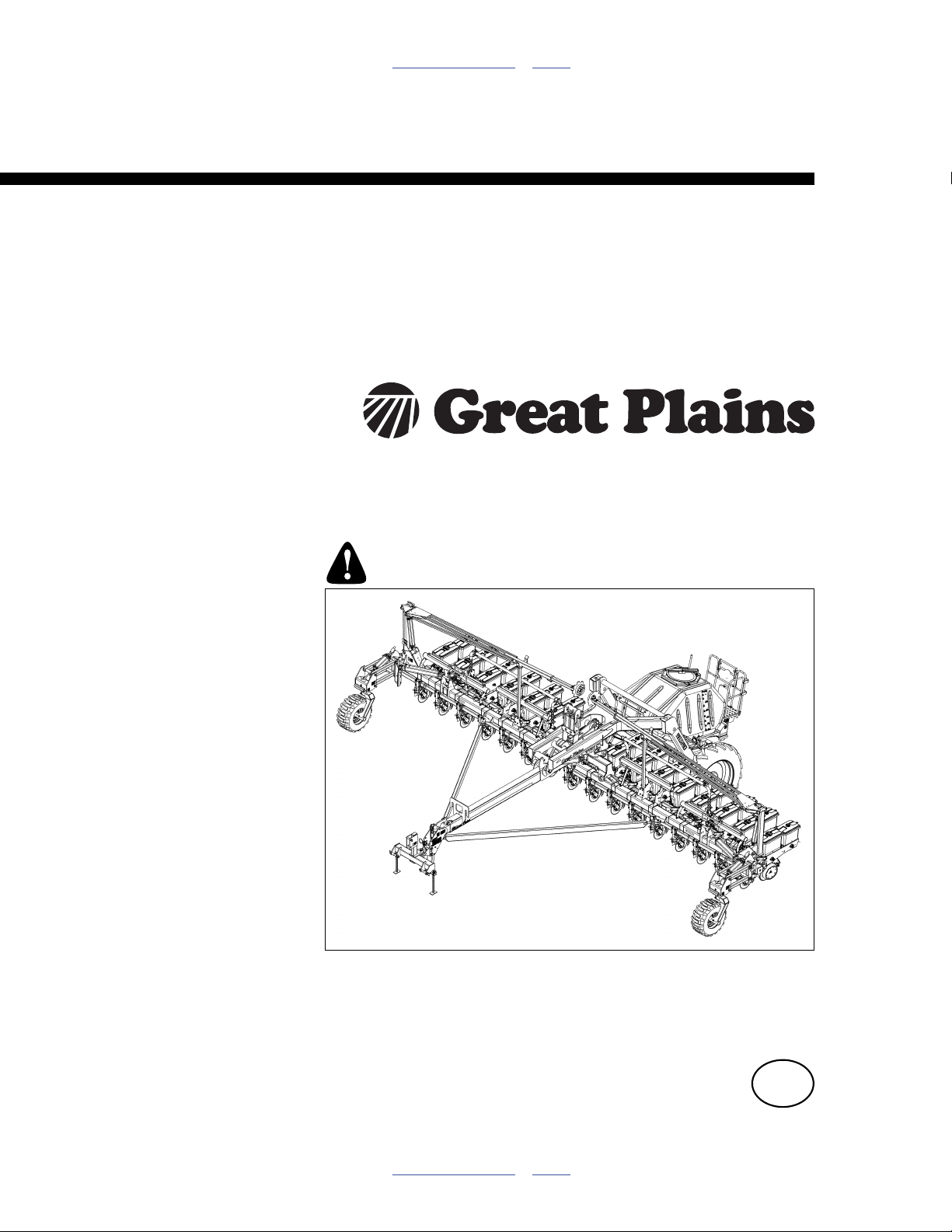
Table of Contents Index
Operator
YP1630F-1630 and YP1630F-1670
12 m 2-Section Yield-Pro® Dry Fertilizer Planters
Manufacturing, Inc.
www.greatplainsmfg.com
Read the operator manual entirely. When you see this symbol, the
subsequent instructions and warnings are serious - follow without
exception. Your life and the lives of others depend on it!
34460
Illustrations may show optional equipment not supplied with standard unit or may
depict similar YP1625/A or PD8070 models where a topic is identical.
ORIGINAL INSTRUCTIONS
© Copyright 2012 Printed 2012-12-27 401-832M
Table of Contents Index
EN

Table of Contents Index
Table of Contents Index

Great Plains Manufacturing, Inc. Cover Index iii
Table of Contents
Important Safety Information ......................................1
Safety Decals .................................................................6
Introduction ................................................................15
Description of Unit ........................................................15
Document Family .........................................................15
Covered Models ...........................................................15
Intended Usage ........................................................15
Using This Manual........................................................15
Definitions................................................................. 15
Owner Assistance ........................................................16
Preparation and Setup ...............................................17
Initial Setup...................................................................17
Pre-Planting Setup .......................................................17
Hitching Tractor to Planter............................................18
Hydraulic Hookup .....................................................18
3-Point Hitch.............................................................18
Hydraulic Hose Hookup............................................ 19
Raising/Lowering Tongue....................................19
Electrical Hookup......................................................20
Store Main Parking Stand.........................................20
Monitor Setup ...............................................................21
Marker Setup (Option)..................................................21
Operating Instructions...............................................22
Pre-Start Checklist .......................................................22
Wing Lock Overview.....................................................22
Unfolding the Planter....................................................23
Prepare Hitched Tractor and Planter........................ 23
Prepare Transport Hooks ......................................... 23
Release Wing Locks................................................. 24
Re-Phase Fold Cylinders..........................................24
Partially Unfold .........................................................24
Lower Tongue ..........................................................24
Fully Unfold ..............................................................24
Remove and Store Transport Locks......................... 25
Unfold Closeout........................................................26
Raising/Lowering Planter .............................................27
Raising Planter .........................................................27
Lowering Planter ......................................................27
Re-phasing Lift System ............................................27
Folding the Planter .......................................................28
Shut off Fan..............................................................28
Set Tractor and Tongue ...........................................28
Raise Planter............................................................28
Install Lock Channels ...............................................29
Activate Fold Solenoid Valves.................................. 29
Begin Folding ........................................................... 29
Raise Tongue...........................................................30
Complete Fold..........................................................30
Lower Tongue .......................................................... 30
Re-phasing Fold System.......................................... 30
Lock Up Dry Fertilizer Drive ..................................... 30
Transporting................................................................. 31
Transport Weights....................................................31
Loading Materials......................................................... 32
For Loading All Materials ......................................... 32
Loading Seed ........................................................... 33
Seed Drive Clutch .................................................... 34
Meter Clutch Disengagement............................... 34
Meter Shaft Alignment.......................................... 34
Loading Fertilizer...................................................... 35
Hopper Safety Information ...................................35
Swing-Down Railing Section ................................ 36
Load Fertilizer ...................................................... 37
Loading Treatments (Option) ................................... 38
Treatment Compatibility .......................................38
Inspect Hoppers ................................................... 38
Set Meters to Zero ............................................... 38
Load Treatment.................................................... 38
Treatment Drive Clutch ............................................ 39
Disabling Unused Drives.............................................. 40
Wing Drive Lockup ................................................... 40
Fertilizer Drive Lockup ............................................. 40
Field Setup Checklist ................................................... 41
Monitor Operation ........................................................ 42
Fan General Operating Information ............................. 42
Starting Fan.............................................................. 42
Stopping Fan............................................................42
Marker Operation ......................................................... 43
Field Operation ............................................................ 44
Parking......................................................................... 45
Storage ........................................................................ 46
Adjustments ............................................................... 47
Setting Material Rates.................................................. 48
Planting (Seed) Rate................................................48
Dry Fertilizer Rate .................................................... 48
Treatment Rate (Option) .......................................... 48
Marker Adjustments ..................................................... 49
Dual Marker Speed Adjustment ............................... 49
Marker Disk Adjustment ........................................... 49
Row Implement Adjustments ....................................... 50
© Copyright 2012 All rights Reserved
Great Plains Manufacturing, Inc. provides this publication “as is” without warranty of any kind, either expressed or implied. While every precaution has been
taken in the preparation of this manual, Great Plains Manufacturing, Inc. assumes no responsibility for errors or omissions. Neither is any liability assumed for
damages resulting from the use of the information contained herein. Great Plains Manufacturing, Inc. reserves the right to revise and improve its products as
it sees fit. This publication describes the state of this product at the time of its publication, and may not reflect the product in the future.
2012-12-27 Cover Index 401-832M
Trademarks of Great Plains Manufacturing, Inc. include: Singulator Plus, Swath Command, Terra-Tine.
Registered Trademarks of Great Plains Manufacturing, Inc. include:
Air-Pro, Clear-Shot, Discovator, Great Plains, Land Pride, MeterCone, Nutri-Pro, Seed-Lok, Solid Stand,
Terra-Guard, Turbo-Chisel, Turbo-Chopper, Turbo Max, Turbo-Till, Ultra-Till, Ver ti-Till, Whirlfilter, Yield-Pro.
Brand and Product Names that appear and are owned by others are trademarks of their respective owners.
Printed in the United States of America

iv YP1630F Table of Contents Index Great Plains Manufacturing, Inc.
Frame-Mounted Row Accessories........................... 50
Frame-Mounted Coulters ..................................... 50
Dry Fertilizer Applicator Adjustments....................... 50
Applicator Release Height.................................... 50
30 Series Row-Unit Adjustments ................................. 51
Row Unit Down Pressure......................................... 52
Unit-Mounted Coulter Adjustments .......................... 53
Row-Unit Opener Disc Adjustments......................... 53
Setting Planting Depth ......................................... 53
Side Gauge Wheel Adjustments .............................. 54
Adjusting Gauge Wheel Scrapers............................ 55
Seed Meter Setup and Adjustment .......................... 56
Exchanging Meters .................................................. 57
Seed Meter Adjustments.......................................... 58
Finger Meter Adjustments .................................... 58
Finger Meter Brush Adjustment ........................... 58
Finger Meter Inserts ............................................. 59
Sunflower Meter Configurations........................... 59
Brush Meter Adjustments..................................... 60
Installing Brush Meter Plates ............................... 60
Seed Firmer Adjustments ........................................ 61
Keeton® Seed Firmer Adjustment........................ 61
Seed-Lok® Seed Firmer Lock-Up ........................ 61
Press Wheel Adjustments........................................ 62
Press Wheel Down Pressure ............................... 62
Press Wheel Centering ........................................ 62
Press Wheel Stagger ........................................... 63
Press Wheel Angle............................................... 63
Troubleshooting......................................................... 64
Planting Rate Problems ............................................... 64
Suggested Furrow Check:.................................... 64
Seed Population Troubleshooting Charts .................... 65
Maintenance and Lubrication ................................... 72
Maintenance ................................................................ 72
Frame Lift Cylinder Locks ........................................ 73
Ground Drive Springs .............................................. 73
Material Unloading and Clean-Out............................... 74
Seed Unloading and Clean-Out ............................... 74
Seed Hopper Clean-Out....................................... 74
Finger Meter Clean-Out ....................................... 75
Brush Meter Clean-Out ........................................ 75
Seed Tube Clean-Out .......................................... 75
Fertilizer Unloading and Clean-Out.......................... 76
Fertilizer Unloading .............................................. 76
Fertilizer Clean-Out.................................................. 77
Problem Clean-Out .............................................. 78
Removing Meter Box............................................ 78
Hopper Entry ........................................................ 79
Treatment Unloading and Clean-Out (Option) ......... 81
Treatment Meter Gate Calibration (Option) ................. 82
Meter Maintenance ...................................................... 83
Finger Pickup Meter Maintenance ........................... 83
Finger Set Inspection ........................................... 83
Finger Meter Re-Assembly Steps.........................83
Precautions...........................................................83
Population Max™ Annual Maintenance................84
Population Max™ Installation ...............................84
Skip Stop™ Annual Maintenance .........................85
Skip Stop™ Installation.........................................85
Exchanging Finger Sets ...............................................86
Install Corn Finger Set ..........................................89
Meter Drive Adjustments ..........................................90
Brush Meter Maintenance.........................................91
Seed Plate Maintenance...........................................92
Cleaning and Storing Seed Disks .........................92
Bleeding Hydraulics ..................................................93
Bleeding Lift Hydraulics ........................................93
Bleeding Fold Cylinder Hydraulics........................93
Bleeding Marker Hydraulics..................................94
Marker Maintenance.....................................................94
Chain Maintenance.......................................................95
30 Series Opener Disks and Scrapers .....................96
30 Series Row-Unit Side Wheels..............................97
Lubrication ....................................................................98
Seed Lubricants..........................................................104
Options and Accessories ........................................105
Appendix A - Reference Information ......................110
Specifications and Capacities.....................................110
YP1630F-1630 30 inch Models ..............................110
YP1630F-1670 70 cm Models ................................111
Tire Inflation Chart ......................................................111
Hydraulic Diagrams ....................................................112
Chain Routing.............................................................115
Torque Values Chart ..................................................119
Appendix C - Initial Setup ........................................120
Hydraulic Charge and Bleed.......................................120
Seed Monitor Console Installation..............................120
Seed Monitor Console Quick-Start .............................120
Power-Up The Console ..........................................121
Set Metric Mode......................................................121
About Row Count and Spacing...............................121
Set Planter Row Count ...........................................122
Set Planter Row Spacing........................................122
Row Setup ..............................................................122
Level Planter...............................................................123
Wing Alignment ..........................................................124
Speed Calibration .......................................................125
Speed Sensor Operation ........................................125
Marker Extension........................................................125
Appendix D - Option Installation.............................126
122-278S Scraper Installation ....................................126
Warranty .....................................................................127
Index ..........................................................................129
401-832M Table of Contents Index 2012-12-27
Great Plains Manufacturing, Inc. Table of Contents Index 1
Important Safety Information
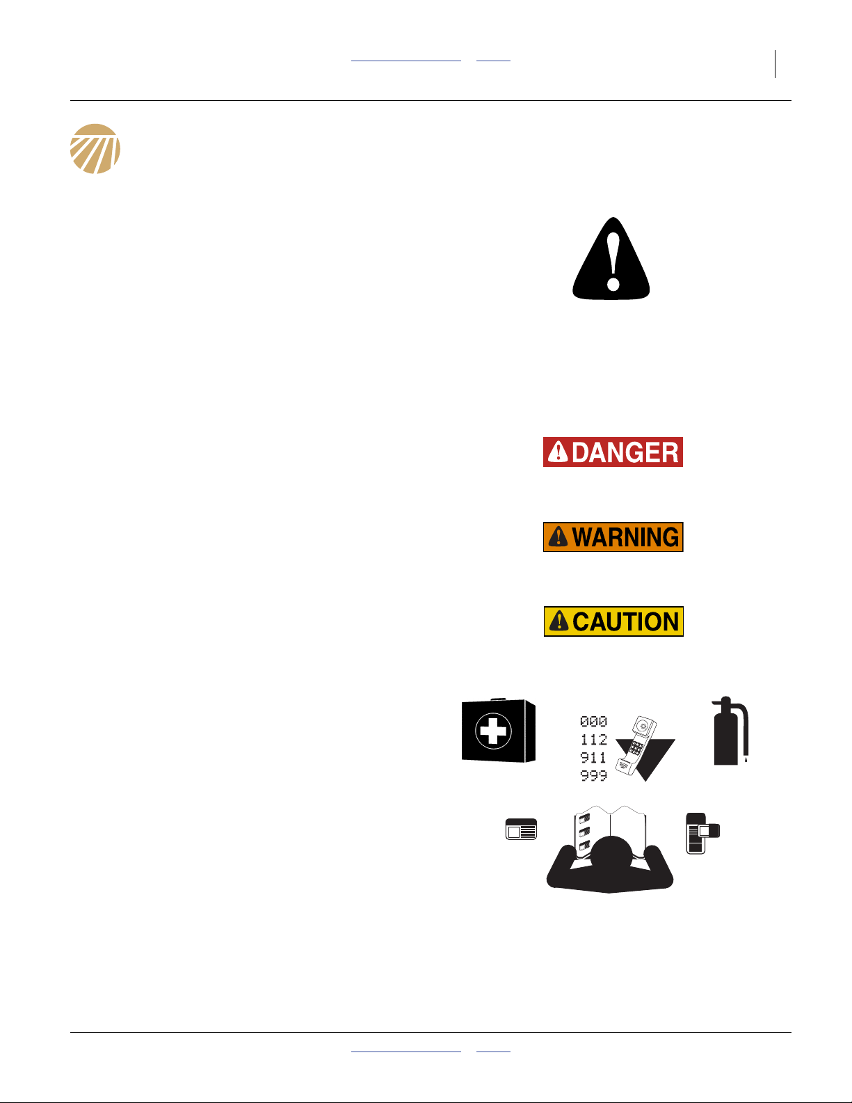
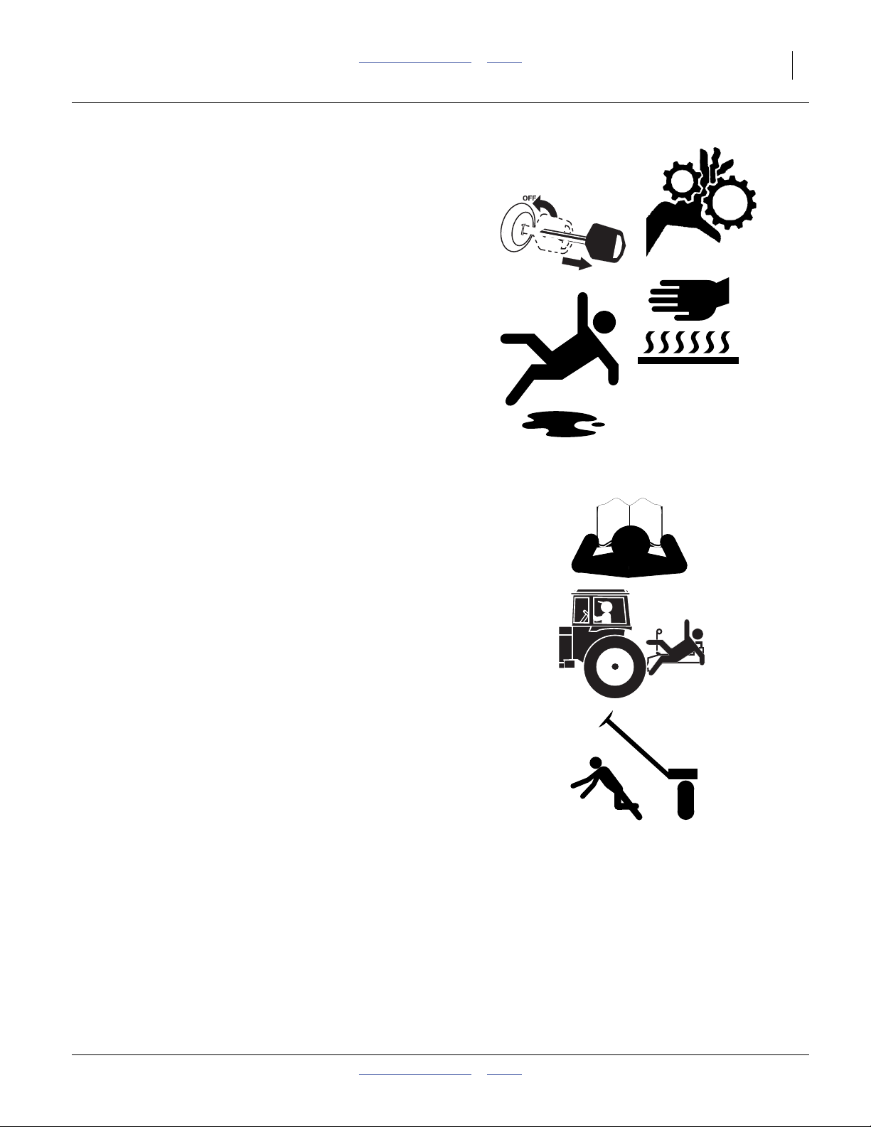
Look for Safety Symbol
The SAFETY ALERT SYMBOL indicates there is a
potential hazard to personal safety involved and extra
safety precaution must be taken. When you see this
symbol, be alert and carefully read the message that
follows it. In addition to design and configuration of
equipment, hazard control and accident prevention are
dependent upon the awareness, concern, prudence and
proper training of personnel involved in the operation,
transport, maintenance and storage of equipment.
Be Aware of Signal Words
Signal words designate a degree or level of hazard
seriousness.
DANGER indicates an imminently hazardous situation
which, if not avoided, will result in death or serious injury.
This signal word is limited to the most extreme situations,
typically for machine components that, for functional
purposes, cannot be guarded.
WARNING indicates a potentially hazardous situation
which, if not avoided, could result in death or serious
injury, and includes hazards that are exposed when
guards are removed. It may also be used to alert against
unsafe practices.
CAUTION indicates a potentially hazardous situation
which, if not avoided, may result in minor or moderate
injury. It may also be used to alert against unsafe
practices.
Prepare for Emergencies
▲ Be prepared if a fire starts
▲ Keep a first aid kit and fire extinguisher handy.
▲ Keep emergency numbers for doctor, ambulance, hospital
and fire department near phone.
Be Familiar with Safety Decals
▲ Read and understand “Safety Decals” on page 6,
thoroughly.
▲ Read all instructions noted on the decals.
▲ Keep decals clean. Replace damaged, faded and illegible
decals.
2012-12-27 Table of Contents Index 401-832M

2 YP1630F Table of Contents Index Great Plains Manufacturing, Inc.
Wear Protective Equipment
Great Plains advises all users of chemical pesticides or
herbicides to use the following personal safety
equipment.
▲ Waterproof, wide-brimmed hat
▲ Waterproof apron.
▲ Face shield, goggles or full face respirator.
▲ Goggles with side shields or a full face respirator is
required if handling or applying dusts, wettable powders, or
granules or if being exposed to spray mist.
▲ Cartridge-type respirator approved for pesticide vapors
unless label specifies another type of respirator.
▲ Waterproof, unlined gloves. Neoprene gloves are
recommended.
▲ Cloth coveralls/outer clothing changed daily; waterproof
items if there is a chance of becoming wet with spray
▲ Waterproof boots or foot coverings
▲ Do not wear contaminated clothing. Wash protective
clothing and equipment with soap and water after each use.
Personal clothing must be laundered separately from
household articles.
▲ Clothing contaminated with certain pesticides must be
destroyed according to state and local regulations. Read
chemical label for specific instructions.
▲ Wear clothing and equipment appropriate for the job. Avoid
loose-fitting clothing.
▲ Prolonged exposure to loud noise can cause hearing
impairment or loss. Wear suitable hearing protection such
as earmuffs or earplugs.
▲ Avoid wearing entertainment headphones while operating
machinery. Operating equipment safely requires the full
attention of the operator.
Avoid High Pressure Fluids
Escaping fluid under pressure can penetrate the skin,
causing serious injury.
▲ Avoid the hazard by relieving pressure before disconnecting
hydraulic lines.
▲ Use a piece of paper or cardboard, NOT BODY PARTS, to
check for suspected leaks.
▲ Wear protective gloves and safety glasses or goggles when
working with hydraulic systems.
▲ If an accident occurs, seek immediate medical assistance
from a physician familiar with this type of injury.
401-832M Table of Contents Index 2012-12-27
Great Plains Manufacturing, Inc. Table of Contents Index Important Safety Information 3
Handle Chemicals Properly
▲ Read and follow chemical manufacturer’s instructions.
▲ Wear protective clothing.
▲ Handle all chemicals with care.
▲ Agricultural chemicals can be dangerous. Improper use can
seriously injure persons, animals, plants, soil and property.
▲ Inhaling smoke from any type of chemical fire is a serious
health hazard.
▲ Store or dispose of unused chemicals as specified by the
chemical manufacturer.
▲ Immediately and thoroughly flush any area of the body that
is contaminated by chemicals.
▲ If chemical is swallowed, carefully follow the chemical
manufacturer’s recommendations and consult with a doctor.
▲ If persons are exposed to a chemical in a way that could
affect their health, consult a doctor immediately with the
chemical label or container in hand. Any delay could cause
serious illness or death.
▲ Dispose of empty chemical containers properly. By law
rinsing of the used chemical container must be repeated
three times. Puncture the container to prevent future use. An
alternative is to jet-rinse or pressure rinse the container.
▲ After working with chemicals, wash hands and face before
eating. Shower when application is completed for the day.
▲ Never wash out the tanks within 100 feet (30m) of any
freshwater source or in a car wash.
▲ Rinse out the tank. Apply rinse water on last field treated.
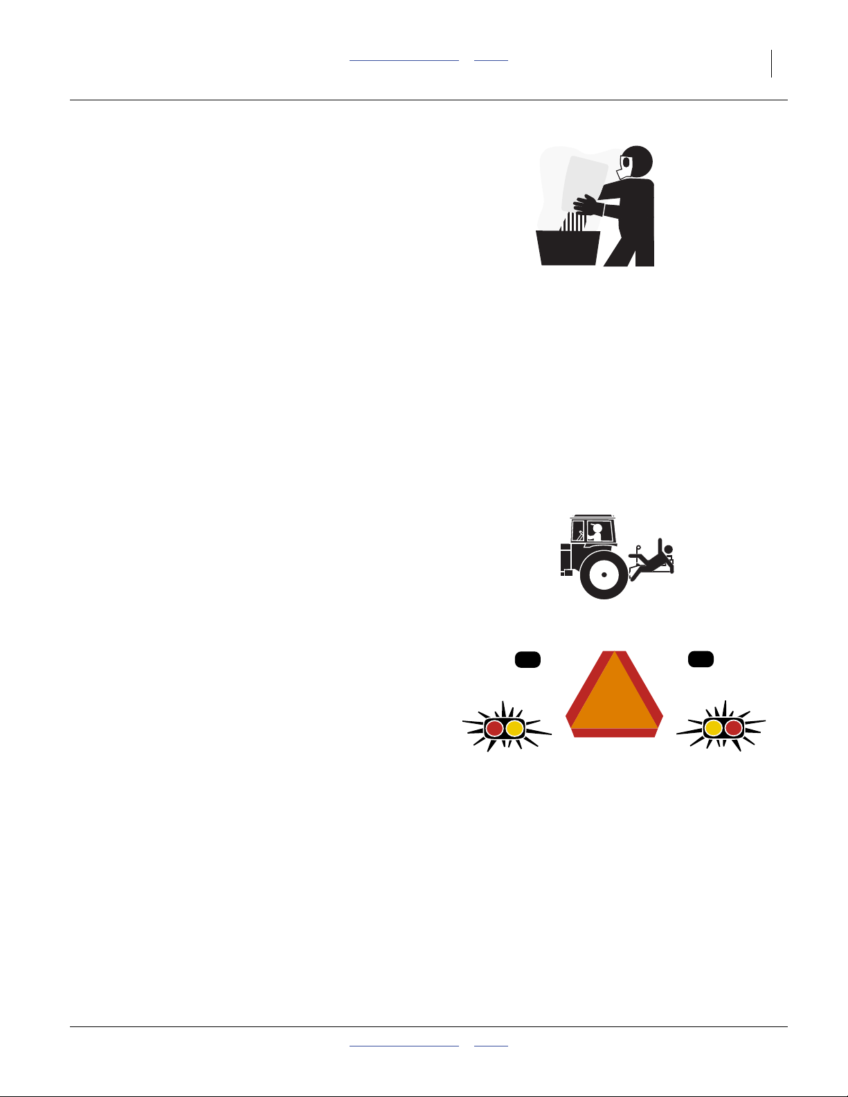
Keep Riders Off Machinery
Riders obstruct the operator’s view. Riders could be
struck by foreign objects or thrown from the machine.
▲ Never allow children to operate equipment.
▲ Keep all bystanders away from machine during operation.
Use Safety Lights and Devices
Slow-moving tractors and towed implements can create
a hazard when driven on public roads. They are difficult
to see, especially at night.
▲ Use flashing warning lights and turn signals whenever
driving on public roads.
▲ Use lights and devices provided with implement
2012-12-27 Table of Contents Index 401-832M
4 YP1630F Table of Contents Index Great Plains Manufacturing, Inc.
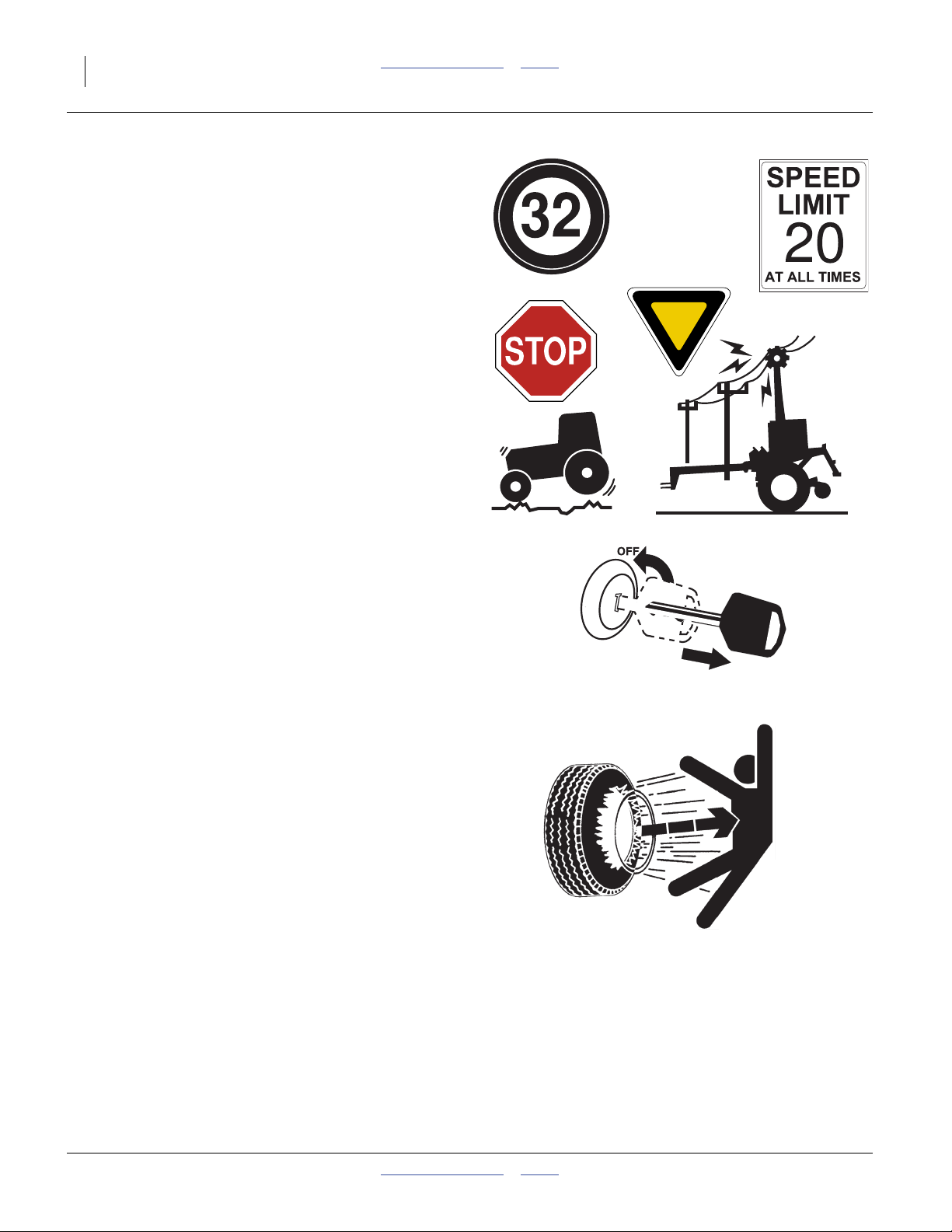
Transport Machinery Safely
Maximum transport speed for implement is 32 km/h
(20 mph). Some rough terrains require a slower speed.
Sudden braking can cause a towed load to swerve and
upset.
▲ Do not exceed 32 km/h (20 mph). Never travel speeds which
do not allow adequate control of steering and stopping.
Reduce speed if towed load is not equipped with brakes.
▲ Comply with state and local laws.
▲ Do not tow an implement that, when fully loaded, weighs
more than 1.5 times the weight of towing vehicle.
▲ Carry reflectors or flags to mark planter in case of
breakdown on the road.
▲ Keep clear of overhead power lines and other obstructions
when transporting. Refer to transport dimensions under
“Specifications and Capacities” on page 110.
▲ Do not fold or unfold the planter while the tractor is
moving.
Shutdown and Storage
▲ Lower planter, put tractor in park, turn off engine, and
remove the key.
▲ Block tires with wheel chocks provided.
▲ Secure planter using blocks and supports provided.
▲ Detach and store planter in an area where children
normally do not play.
Tire Safety
Tire changing can be dangerous and should be
performed by trained personnel using correct tools and
equipment.
▲ When inflating tires, use a clip-on chuck and extension hose
long enough for you to stand to one side–not in front of or
over tire assembly. Use a safety cage if available.
▲ When removing and installing wheels, use wheel-handling
equipment adequate for weight involved.
401-832M Table of Contents Index 2012-12-27
Great Plains Manufacturing, Inc. Table of Contents Index Important Safety Information 5
Practice Safe Maintenance
▲ Understand procedure before doing work. Use proper tools
and equipment. Refer to this manual for additional
information.
▲ Work in a clean, dry area.
▲ Lower the planter, put tractor in park, turn off engine, and
remove key before performing maintenance.
▲ Make sure all moving parts have stopped and all system
pressure is relieved.
▲ Allow planter to cool completely.
▲ Disconnect battery ground cable (-) before servicing or
adjusting electrical systems or before welding on planter.
▲ Inspect all parts. Make sure parts are in good condition and
installed properly.
▲ Remove buildup of grease, oil or debris.
▲ Remove all tools and unused parts from planter before
operation.
Safety At All Times
Thoroughly read and understand the instructions in this
manual before operation. Read all instructions noted on
the safety decals.
▲ Be familiar with all planter functions.
▲ Operate machinery from the driver’s seat only.
▲ Do not leave planter unattended with tractor engine
running.
▲ Do not dismount a moving tractor. Dismounting a moving
tractor could cause serious injury or death.
▲ Do not stand between the tractor and planter during
hitching.
▲ Keep hands, feet and clothing away from power-driven
parts.
▲ Wear snug-fitting clothing to avoid entanglement with
moving parts.
▲ Watch out for wires, trees, etc., when folding and raising
planter. Make sure all persons are clear of working area.
2012-12-27 Table of Contents Index 401-832M
6 YP1630F Table of Contents Index Great Plains Manufacturing, Inc.
Safety Decals
Safety Reflectors and Decals
Your implement comes equipped with all lights, safety
reflectors and decals in place. They were designed to
help you safely operate your implement.
▲ Read and follow decal directions.
▲ Keep lights in operating condition.
▲ Keep all safety decals clean and legible.
▲ Replace all damaged or missing decals. Order new decals
from your Great Plains dealer. Refer to this section for
proper decal placement.
▲ When ordering new parts or components, also request
corresponding safety decals.
To install new decals:
1. Clean the area on which the decal is to be placed.
2. Peel backing from decal. Press firmly on surface,
being careful not to cause air bubbles under decal.
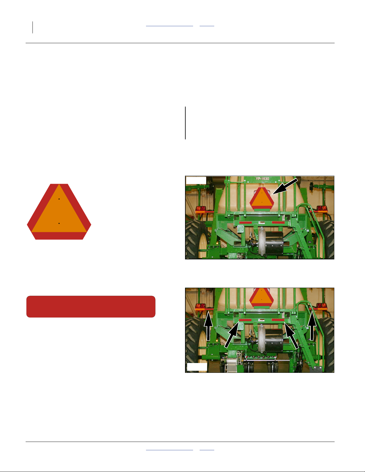
818-055C
Slow Moving Vehicle Reflector
On the back of the planter, walkboard center;
1 total
See “Transporting” on page 31.
838-266C
Red Reflectors
On the back of fertilizer hopper frame each end,
and on the inside rear face of each light mounting bar;
4 total
34535
34535
401-832M Table of Contents Index 2012-12-27
Great Plains Manufacturing, Inc. Table of Contents Index Important Safety Information 7
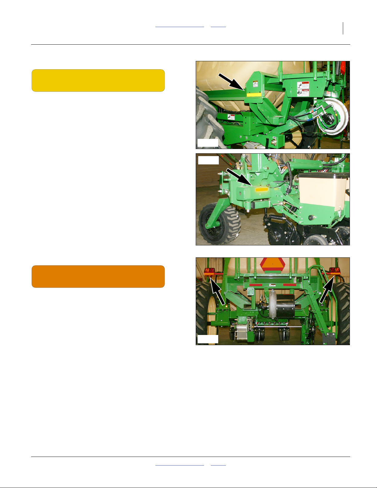
838-265C
Amber Reflectors
One each on rear face of wing tool bar at wing lock,
one each rear outside corner face of fertilizer frame;
4 total
34536
34537
838-267C
Daytime Reflectors
On the back of seed frame, outside red reflectors,
on the rear face of the light bar;
2 total
34535
2012-12-27 Table of Contents Index 401-832M
8 YP1630F Table of Contents Index Great Plains Manufacturing, Inc.
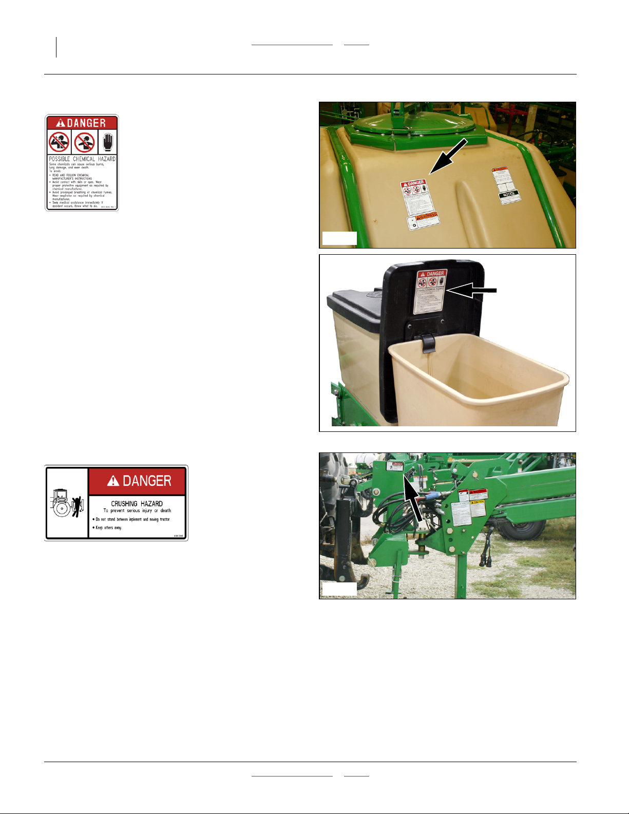
818-323C (Option)
Danger: Chemical Hazard
On the rear walkboard face of the central dry fertilizer
hopper, and on the underside of treatment hopper
(option) lids;
1 or 17 total
34544
34539
818-590C
Danger: Crushing Hazard
On the left side of the 3-point hitch:
1 total.
See “Hitching Tractor to Planter” on page 18.
34541
401-832M Table of Contents Index 2012-12-27

Great Plains Manufacturing, Inc. Table of Contents Index Important Safety Information 9
838-599C
34542
Danger: Electrocution Hazard
On front face of marker mount, near gauge wheel pivot;
2 total
See “Marker Operation” on page 43.
848-583C
Danger: Do Not Ride
On the left and right ends of the walkboard frame;
2 total
818-045C
Warning: Pinch-Crush
On both sides of wing gauge wheel caster weldments;
4 total
34536
34540
2012-12-27 Table of Contents Index 401-832M
10 YP1630F Table of Contents Index Great Plains Manufacturing, Inc.
818-188C
WARNING
EXCESSIVE SPEED HAZARD
To Prevent Serious Injury or Death:
Do Not exceed 20 mph maximum transport
speed. Loss of vehicle control and/or machine
can result.
Warning: Excessive Speed
On left side of tongue near hitch;
1 total
See “Transporting” on page 31.
818-339C
818-188C Rev. C
34541
Warning: High Pressure Fluid Hazard
On left side of tongue near hitch;
1 total
See “Hydraulic Hose Hookup” on page 19.
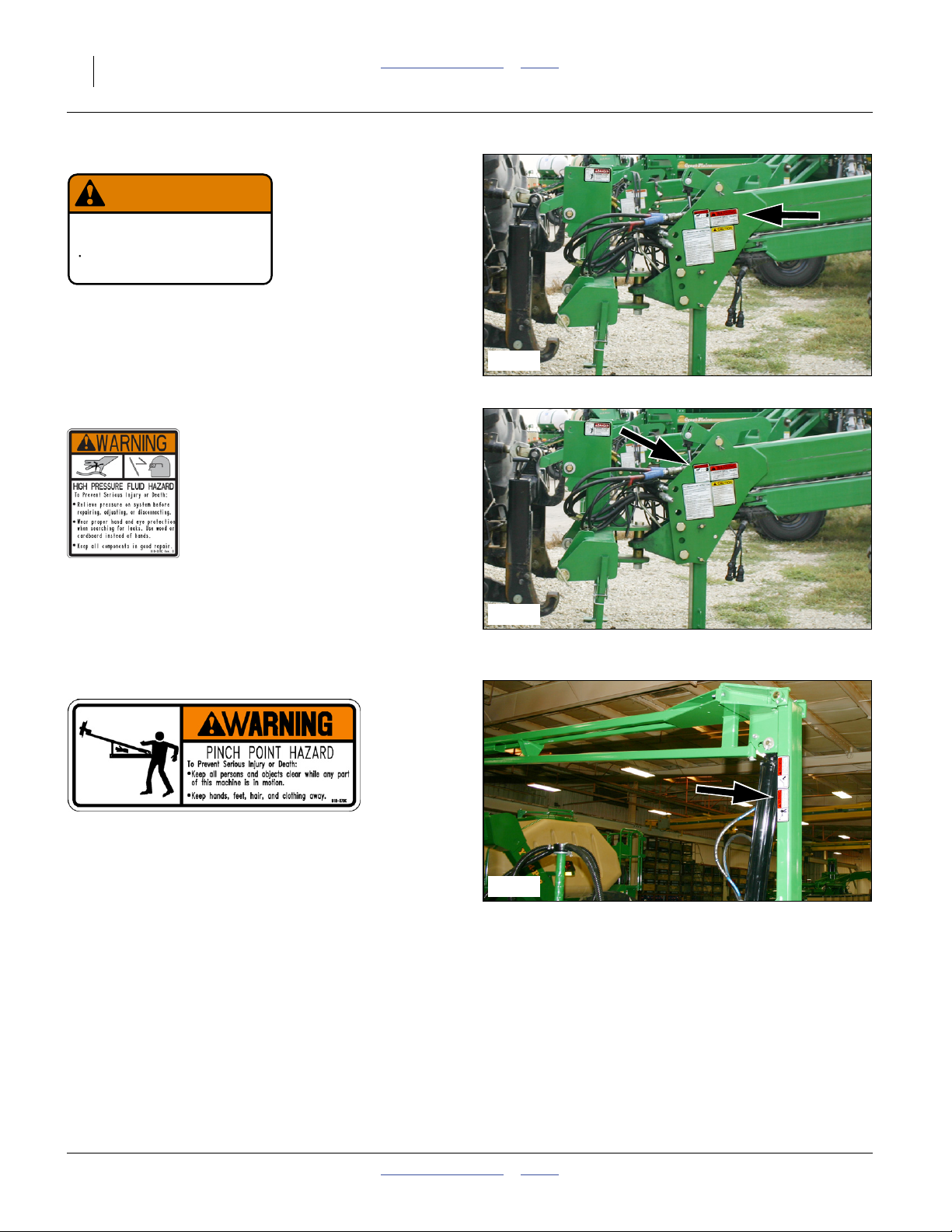
818-579C
Warning: Pinch-Shear Hazard
On marker section each end, two total
See “Marker Operation” on page 43.
34541
34543
401-832M Table of Contents Index 2012-12-27
Great Plains Manufacturing, Inc. Table of Contents Index Important Safety Information 11
818-580C
Warning: Overhead Hazard
On marker section each end, two total
See “Marker Operation” on page 43.
34543
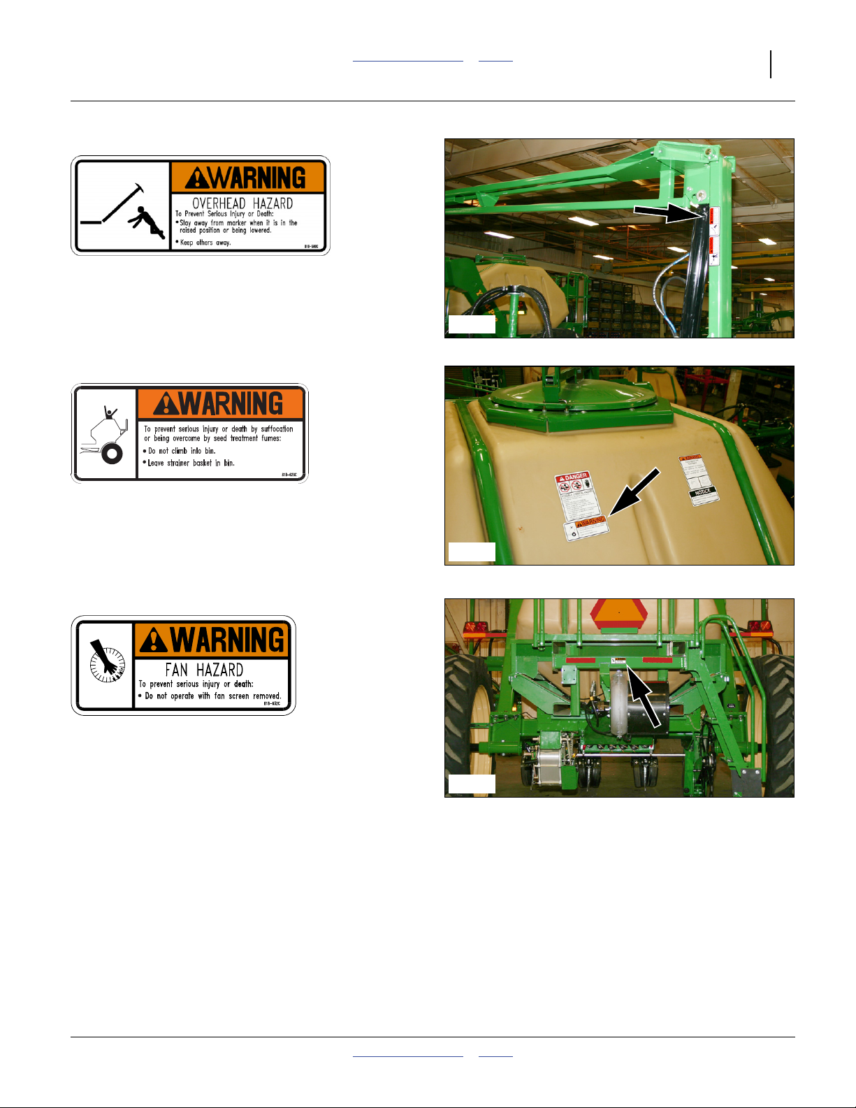
818-628C
Warning: Confined Space
On the rear walkboard face of the central dry fertilizer
hopper;
1 total
818-632C
Warning: Fan Hazard
On center rear face of walkboard frame;
1 total
34544
34535
2012-12-27 Table of Contents Index 401-832M
12 YP1630F Table of Contents Index Great Plains Manufacturing, Inc.
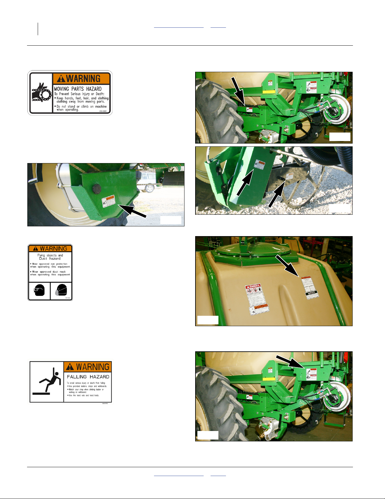
818-860C
Warning: Moving Parts
On outer face of central hopper lower support tubes,
on variable rate gearbox input chain guards,
on all ground drive arm guards
on all removable ground drive guards;
14 total
34536
34546
848-392C
Warning: Eye and Dust Hazards
On the rear walkboard face of the central dry fertilizer
hopper;
1 total
848-575C
34545
34544
Warning: Falling Hazard
On the left and right ends of the walkboard frame;
2 total
34536
401-832M Table of Contents Index 2012-12-27
Great Plains Manufacturing, Inc. Table of Contents Index Important Safety Information 13
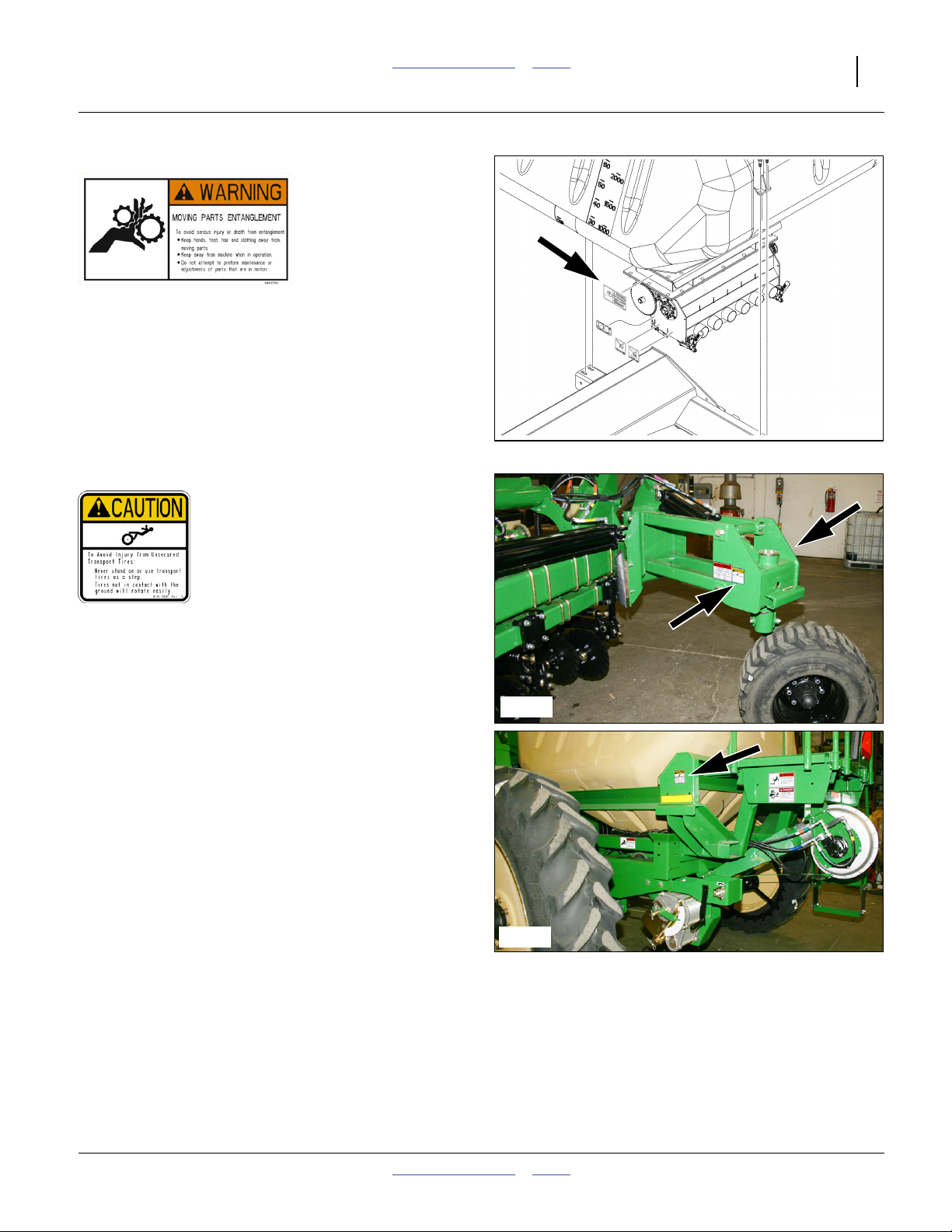
848-576C
Warning: Moving Parts
On inlet of fertilizer meter, above final range gears;
1 total
34410
818-398C
Caution: Tires Not A Step
On both sides of wing gauge wheel caster weldments,
and on rear outer corners of central hopper frame;
4 total
In transport configuration, wing gauge wheels are off the
ground and free to spin. In field configuration, at higher
row unit down-forces, wing gauge wheels may have little
or no ground traction.
34540
34536
2012-12-27 Table of Contents Index 401-832M

14 YP1630F Table of Contents Index Great Plains Manufacturing, Inc.
818-578C
CAUTION
To Avoid Injury or Machine Damage from improper Tire
Inflation or Torquing of Wheel Bolts:
Maximum inflation pressure of tires is 65 psi.
Torque wheel bolts to 240 lb-ft.
Caution: Tire Pressure
On hubcap side rim of each gauge wheel;
2 total
838-995C
818-578C
34547
Caution: General
On right side of tongue near hitch;
1 total
858-011C
CAUTION
To Avoid Injur y or Machine Damage from Improper Tire
Inflation or Torquing of Wheel Bolts:
Maximum inflation pressure of tires is 49 psi (338 kPa).
Torque wheel bolts to 315 ft-lb (427 N-m).
Warning: Tire Pressure
On outside rim of each main transport wheel;
2 total
858-011C
34541
34548
401-832M Table of Contents Index 2012-12-27
Great Plains Manufacturing, Inc. Table of Contents Index 15
Introduction
Great Plains welcomes you to its growing family of new
product owners. This planter has been designed with
care and built by skilled workers using quality materials.
Proper setup, maintenance, and safe operating practices
will help you get years of satisfactory use.
Description of Unit
The YP1630F 12 m 2-Section Yield-Pro
Dry Fertilizer Planters are pull-type planting implements
for use in conventional till, minimum-till, or light no-till
conditions.
®
Yield-Pro
row-units, finger pickup or brush seed meters and row
seed hoppers. Dry fertilizer is air-delivered from a central
bulk hopper. Optional treatment hoppers are available for
rows. Optional unit-mounted coulters are suitable for light
to moderate no-till conditions only. The planter folds for
4.0 m (Narrow) or 4.2 m (Wide) transport.
Planters have 30 Series, side-depth-control
®
Document Family
401-832M Operator Manual (this manual)
401-832B Seed Rate Manual
401-832P Parts Manual
11001-1372
Bulletin A-27aDwyer Magnehelic® instructions
a. These are supplier part numbers.
a
DICKEY-john® PM400 Console Manual
Covered Models
All Models are 16 Row
YP1630F-1630ND 30 inch, Narrow, Dual row hoppers
YP1630F-1630NS 30 inch, Narrow, Single row hopper
YP1630F-1630WD30 inch, Wide, Dual row hopper
YP1630F-1630WS 30 inch, Wide, Single row hopper
YP1630F-1670ND 70 cm, Narrow, Dual row hopper
YP1630F-1670NS 70 cm, Narrow, Single row hopper
YP1630F-1670WD70 cm, Wide, Dual row hopper
YP1630F-1670WS 70 cm, Wide, Single row hopper
Intended Usage
Use the planter to seed production-agriculture crops
only. Do not modify the planter for use with attachments
other than Great Plains options and accessories
specified for use with the planter.
R
L
Figure 1
Left/Right Convention
34460
Using This Manual
This manual familiarizes you with safety, assembly,
operation, adjustments, troubleshooting and
maintenance. Read it and follow the recommendations to
help ensure safe and efficient operation.
The information in this manual is current at printing.
Some parts may change to assure top performance.
Definitions
The following terms are used throughout this manual.
Right-hand and left-hand as used in
this manual are determined by facing
the direction the machine will travel
while in use unless otherwise stated.
An orientation rose in some line art
illustrations shows the directions of:
Up, Back, Left, Down, Front, Right.
Economic and/or Liability Risks:
A crucial point of information related to the preceding topic.
Read and follow the directions provided before continuing, to
ensure safety, avoidance of machine damage, and to achieve
desired field results.
Note: This format indicates a useful point of information
related to the preceding topic.
R
F
U
B
L
D
2012-12-27 Table of Contents Index 401-832M
16 YP1630F Table of Contents Index Great Plains Manufacturing, Inc.
Owner Assistance
If you need customer service or repair parts, contact a
Great Plains dealer. They have trained personnel, repair
parts, and equipment specially designed for Great Plains
products.
Refer to Figure 2
Your planter’s parts were specially designed and should
only be replaced with Great Plains parts. Always use the
serial and model number when ordering parts from your
Great Plains dealer. The serial-number plate is located
near the right main transport tire, on the rear face of the
right riser of the front frame weldment.
Record your Planter model and serial number here for
quick reference:
Model Number:__________________________
Serial Number: __________________________
Your Great Plains dealer wants you to be satisfied with
your new machine. If you do not understand any part of
this manual or are not satisfied with the service received,
please take the following actions.
1. Discuss the matter with your dealership service
manager. Make sure they are aware of any problems
so they can assist you.
2. If you are still unsatisfied, seek out the owner or
general manager of the dealership.
Figure 2
Serial Number Plate
For further assistance write to:
Product Support
Great Plains Mfg. Inc., Service Department
PO Box 5060
Salina, KS 67402-5060
34535
401-832M Table of Contents Index 2012-12-27

Great Plains Manufacturing, Inc. Table of Contents Index 17
Preparation and Setup
This section helps you prepare your tractor and planter
for use. Before using the YP1630F in the field, you must
hitch the planter to a suitable tractor and level the
planter.
Initial Setup
If the planter has just been delivered, or broken down for
re-shipment, these items need to be completed prior to
first field use:
“Appendix C - Initial Setup” on page 120, which
includes:
“Hydraulic Charge and Bleed” page 120,
“Seed Monitor Console Installation” page 120,
“Seed Monitor Console Quick-Start” page 120,
“Level Planter” page 123,
“Wing Alignment” page 124,
“Speed Calibration” page 125, and
“Marker Extension” on page 125.
You may also need to install features, options and
accessories that were not factory- or dealer-installed.
Pre-Planting Setup
The balance of this section covers items that need to be
completed or checked prior to each field use of the
planter.
1. Read and understand “Important Safety
Information” on page 1.
2. Check that all working parts are moving freely, bolts
are tight, and cotter pins are spread.
3. Check that all grease fittings are in place and
lubricated. See “Lubrication” on page 98.
4. Check that all safety decals and reflectors are
correctly located and legible. Replace if damaged.
See “Safety Decals” on page 6.
5. Inflate tires to pressure recommended and tighten
wheel bolts as specified. See “Tire Inflation Chart”
on page 111.
6. If returning the planter to service from storage,
remove any grease used to protect cylinder rods.
2012-12-27 Table of Contents Index 401-832M
18 YP1630F Table of Contents Index Great Plains Manufacturing, Inc.
Hitching Tractor to Planter
Crushing Hazard:
Do not stand or place any part of your body between planter
and moving tractor. You may be severely injured or killed by
being crushed between the tractor and planter. Stop tractor
engine and set park brake before attaching cables and hoses.
Hydraulic Hookup
High Pressure Fluid Hazard:
Relieve pressure before disconnecting hydraulic lines.
Escaping fluid under pressure can have sufficient pressure to
penetrate the skin causing serious injury. Use a piece of paper
or cardboard, NOT BODY PARTS, to check for leaks. Wear
protective gloves and safety glasses or goggles when working
with hydraulic systems. If an accident occurs, seek immediate
medical attention from a physician familiar with this type of
injury.
3-Point Hitch
Refer to Figure 3
7. Connect your tractor 3-point to the planter 3-point
hitch. If using quick hitch be sure planter locks into
hitch securely.
8. Set tractor brakes and/or put tractor in Park.
9. Raise tractor 3-point just enough to relieve pressure
off of the parking stand.
10. Store 3-point stands . There are two methods:
a. Remove lower pins . Swing stand under hitch.
Reinsert pin beneath stand at inner hole.
b. Remove both pins. Invert stand. Re-pin.
Load Sway Hazard:
Adjust 3-point hitch arms and sway blocks to minimize any
side-to-side sway to assure proper tracking in the field, and
safe road travel.
1
2
2
Figure 3
3-Point Hitch Stands Stored
1
29732
401-832M Table of Contents Index 2012-12-27
Great Plains Manufacturing, Inc. Table of Contents Index Preparation and Setup 19
Hydraulic Hose Hookup
Refer to Figure 4
Great Plains hydraulic hoses have color coded handle
grips to help you hookup hoses to your tractor outlets.
Hoses that go to the same remote valve are marked with
the same color.
To distinguish hoses on the same hydraulic circuit, refer
to the symbol molded into the handle grip. Hoses with an
extended-cylinder symbol feed cylinder base ends.
Hoses with a retracted-cylinder symbol feed cylinder rod
ends.
For hydraulic fan and drive motors, connect the hose
under the retracted cylinder symbol to the pressure side
of the motor. Connect the hose under the extended
cylinder symbol to the return side of the motor.
If the tractor has a limited number of remotes capable of
continuous flow, use one for the hydraulic fan. (See
“Specifications and Capacities” on page 110 for tractor
requirements.)
Figure 4
Color Coded Hose Handles
Color Coded Hose Handles
Color Hydraulic Function
Gray Fold/Marker
Blue Lift
Black Fan
31733
Raising/Lowering Tongue
In addition to hitching, tongue raising and lowering is
required during fold and unfold to engage and disengage
the wing locks. The planter tongue is raised and lowered
by raising and lowering the 3-point.
11. Set the initial tongue height. Distance , measured
h
at top of tongue tube is:
42 inches (107 cm) above ground level
Additional planter leveling information is found on
page 123.
12. Connect other hydraulic hoses to tractor remotes.
See “Hydraulic Hose Hookup” on page 19.
h
Figure 5
Tongue Height
25316
2012-12-27 Table of Contents Index 401-832M
20 YP1630F Table of Contents Index Great Plains Manufacturing, Inc.
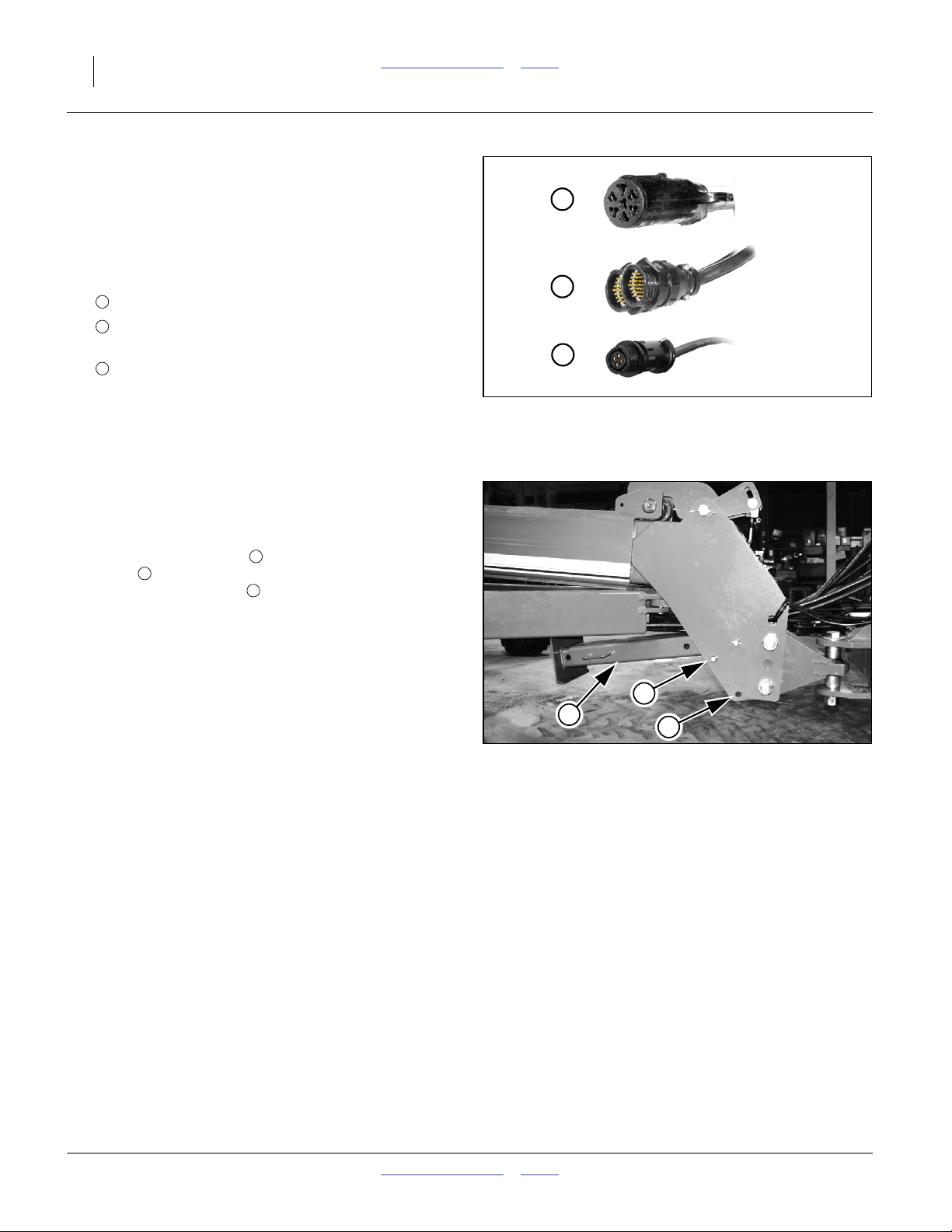
Electrical Hookup
Refer to Figure 6 (depicting an SAE J560b lighting
connector; your connector may vary if it has been replaced
due to different electrical conventions)
Your planter is equipped with systems that require
separate electrical connections. For future reference,
note any optional connectors on this checklist.
a
❑ Lighting connector (standard)
b
❑ Monitor connector (standard, See page 120 for
console installation.)
c
❑ Speed Sensor connector (standard)
❑ __________________________
Make sure tractor is shut down with accessory power off
before making connections.
a
b
c
Figure 6
Connector Identification
25236
31033
31950
Store Main Parking Stand
Refer to Figure 7
13. Raise the 3-point hitch slightly.
14. Remove the lower pin holding the parking
stand . Swing the parking stand back and up until it
is above the rear hole . Place the holding pin in the
rear hole and allow the parking stand to rest on it.
This is the transport position for the parking stand.
15. Adjust the top link of a 3-point long enough so the
ball swivel does not bottom out when fully raised.
16. Secure hoses using hose post loops (not shown) so
that hoses have ample slack for lifts and turns, but
cannot get caught in tongue lock or ball swivel.
Failure to do so could cause hose to be crushed
requiring hose replacement.
7
5
6
6
7
Storing Parking Stand
5
Figure 7
22813
401-832M Table of Contents Index 2012-12-27

Great Plains Manufacturing, Inc. Table of Contents Index Preparation and Setup 21
Monitor Setup
Refer to Figure 8
The standard DICKEY-john® PM400 system monitors
the following elements of a YP1630F planter:
• seeds at each row unit seed tube;
• dry fertilizer at each tower outlet;
• ground speed; and,
• fertilizer meter shaft speed.
See “Seed Monitor Console Installation” on page 120.
Refer to the DICKEY-john® PM400 Console Manual
(11001-1372) for monitor operations.
After installation, and prior to first field use, the monitor
must be setup with the row spacing and speed sensor
constant, as well as your preferences for information
display. Row count is auto-assigned, but any other
DICKEY-john
your planter.
Row spacing data may be found in the Appendix.
For speed setup, Great Plains recommends using the
122 m (400-foot) speed calibration described in the
DICKEY-john® manual. Perform the calibration run in
representative field conditions, as soil conditions, surface
looseness and other tillage practices can cause
variations in the effective rolling radius of the ground
drive wheel.
Prior to each planting session, set any desired limits for
speed and population for the current crop.
®
defaults are not likely to be correct for
Figure 8
Monitor Primary Screen
31807
Marker Setup (Option)
Prior to first use, check and adjust:
•“Dual Marker Speed Adjustment” on page 49.
Prior to first use, and whenever changing row spacings,
set or reset:
•“Marker Extension” on page 125.
Prior to each planting session, check and adjust:
•“Marker Disk Adjustment” on page 49.
2012-12-27 Table of Contents Index 401-832M
22 YP1630F Table of Contents Index Great Plains Manufacturing, Inc.
Operating Instructions
This section covers general operating procedures.
Experience, machine familiarity and the following
information will lead to efficient operation and good
working habits. Always operate farm machinery with
safety in mind.
Pre-Start Checklist
1. Carefully read “Important Safety Information” on
page 1.
2. Lubricate planter as indicated under “Lubrication”
on page 98.
3. Check all tires for proper inflation. See “Tire
Inflation Chart” on page 111.
4. Check all bolts, pins and fasteners. Torque as shown
in “Torque Values Chart” on page 119.
5. Check planter for worn or damaged parts. Repair or
replace parts before going to the field.
6. Check hydraulic hoses, fittings and cylinders for
leaks. Repair or replace before going to the field.
7. Be sure hydraulic hoses are securely held out of the
ball swivel area at hitch. Failure to do so could cause
hoses to pinch requiring hose replacement.
High Pressure Fluid Hazard:
Check all hydraulic lines and fittings before applying pressure.
Escaping fluid under pressure can have sufficient pressure to
penetrate the skin. Fluid escaping from a very small hole can
be almost invisible. Use paper or cardboard, not body parts,
and wear heavy gloves to check for suspected leaks. If an
accident occurs, seek immediate medical attention from a
physician familiar with this type of injury.
1
4
2
2
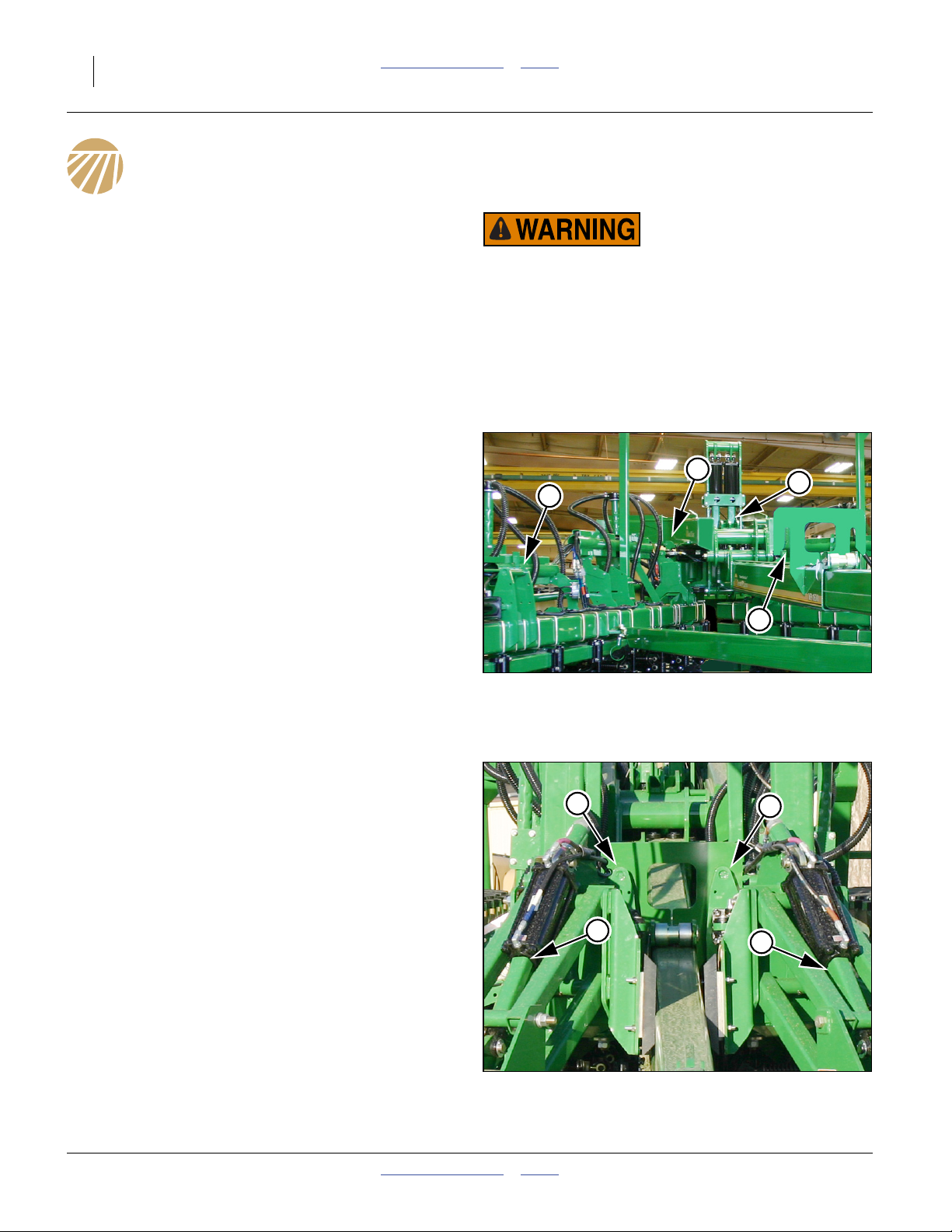
Wing Lock Overview
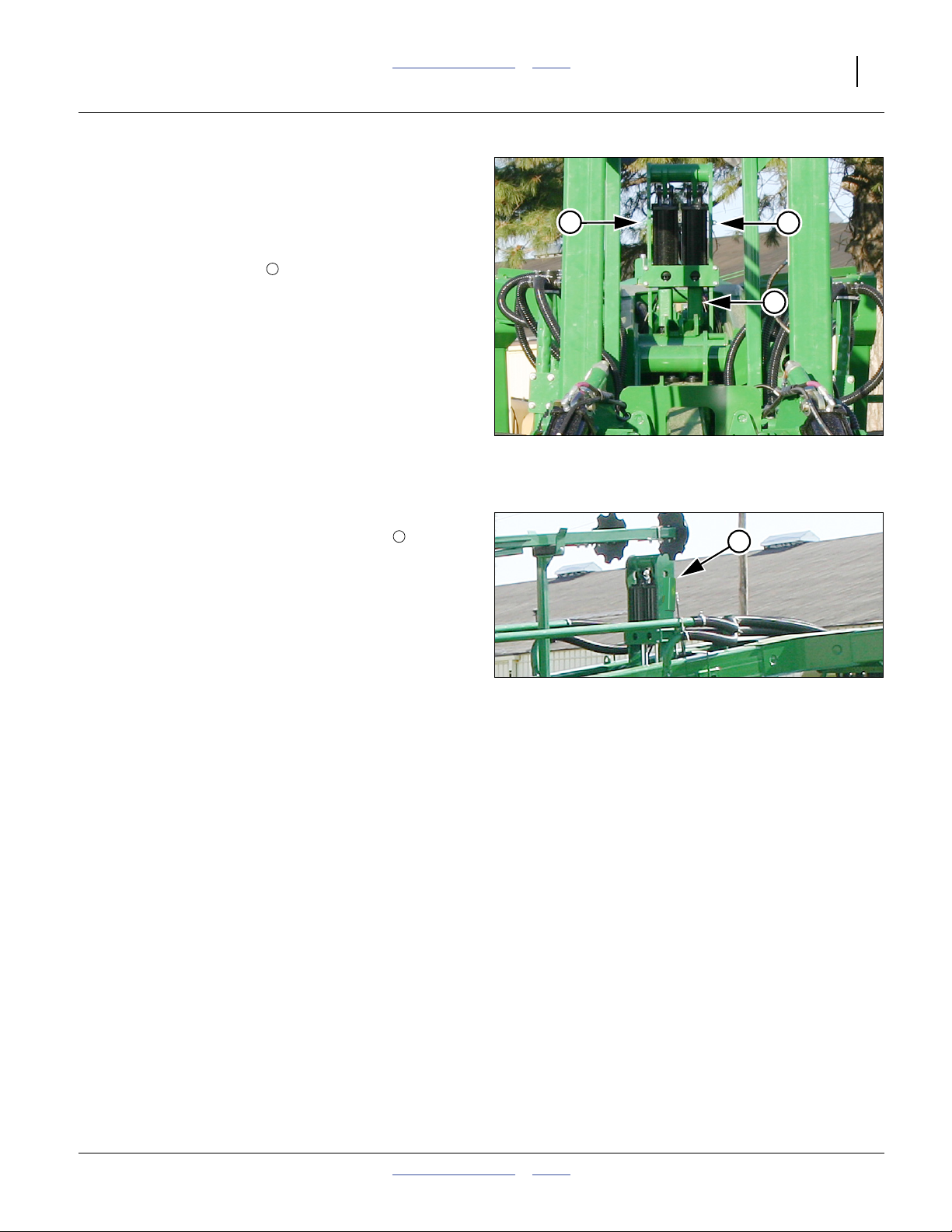
Refer to Figure 9 and Figure 10
The YP1630F planters include four sets of locks for the
frame and wings:
1. Transport hooks behind the wing pivots:
These prevent the planter frame from fully lowering
when folded. The planter frame is raised to allow the
wings to clear the hooks. See page 23 and 28.
2. Wing locks at mid-tongue and inside wing casters:
These prevent the planter from unfolding while in
transport. The tongue (hitch) is raised to allow the
hooks to clear the locks. See page 24 and 28.
3. Transport lock channels at wing caster cylinders:
These lock channels prevent the frame from fully
lowering during transport and maintenance. They
are installed prior to folding, and removed after
unfolding. See page 25 and 29.
4. Lift cylinder lock channels above frame pivots:
These lock channels are only required during
maintenance. However, if installed, they must be
removed after unfolding. See page 25 and 73.
Figure 9
Lift Locks and Transport Hook
2
3
Figure 10
Wing Lock and Transport Locks
2
3
34571
34550
401-832M Table of Contents Index 2012-12-27
Great Plains Manufacturing, Inc. Table of Contents Index Operating Instructions 23
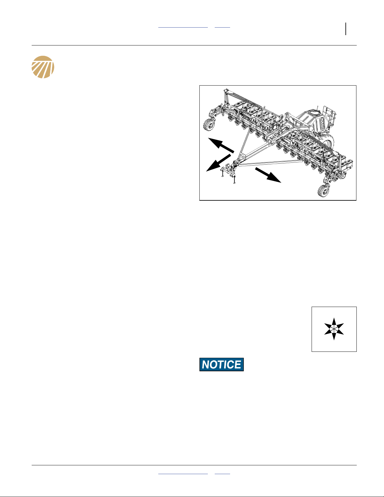
Unfolding the Planter
The distance between the tractor and the central cart
decreases by about 10 feet (3 m) during unfolding.
Planter, tractor, or both will move during this operation.
Crushing, Pinch-Point and Overhead Hazards:
To prevent serious injury or death:
▲ Unfold only on hard level ground. Allow ample room.
▲ Allow no one on or near the planter during unfolding.
▲ Stay clear of the wing sweep arcs. The sweep arcs of the
wings have numerous pinch and crush points in the
mechanism. Coulters and row openers are sharp.
▲ Allow no one near planter during unfold. The fertilizer cart
usually moves forward during unfolding.
▲ Do not unfold with planter lowered.
▲ Unfold only with markers resting in transport cradles.
▲ Unfold only if hydraulics are bled free of air and fully
charged with hydraulic oil.
F
Prepare Hitched Tractor and Planter
1. Move planter to level ground.
2. If tractor movement is not desired, put tractor in Park
and/or set parking brakes, or telescoping movement
of planter may cause tractor to move backward.
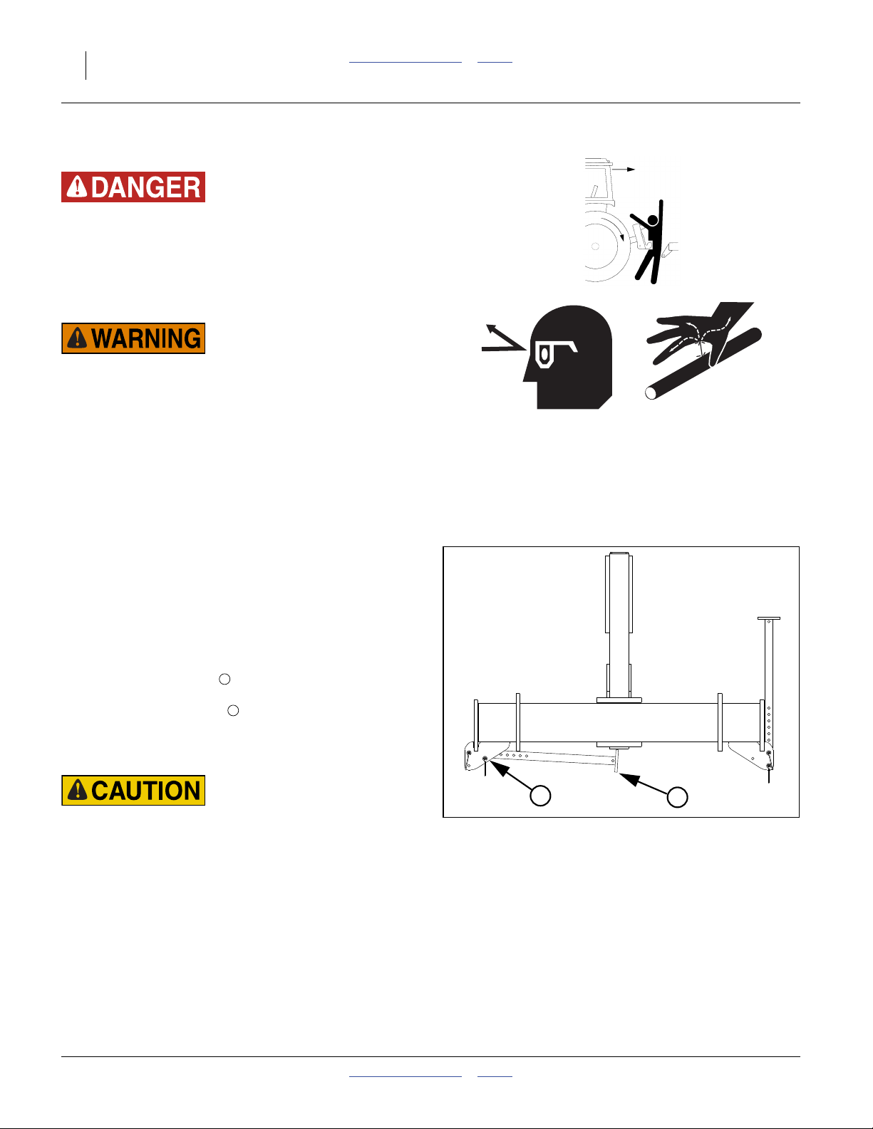
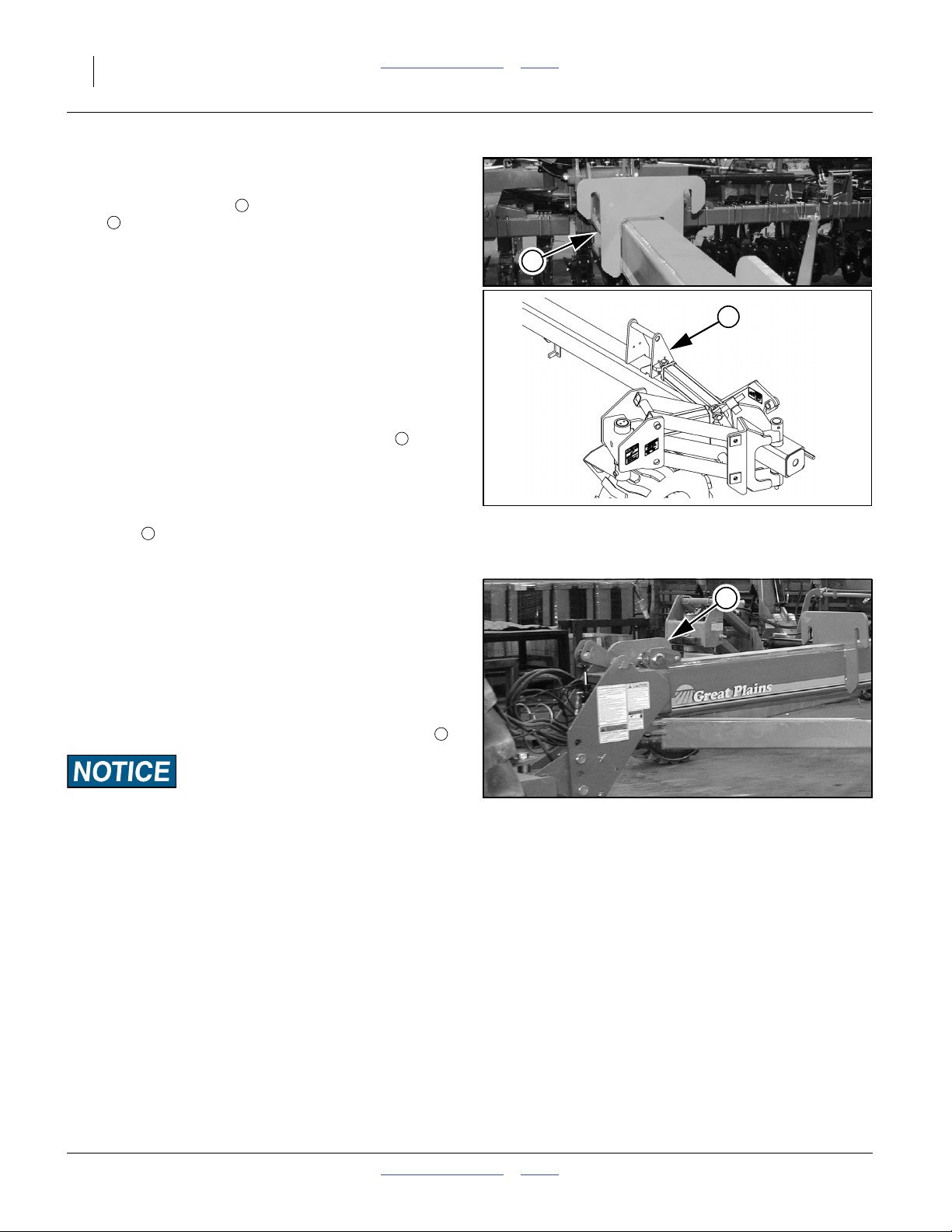
Prepare Transport Hooks
Refer to Figure 12
The transport hooks , behind/above wing pivots,
prevent the frame from fully lowering when the planter is
fully folded. To clear the hooks, the frame is fully raised.
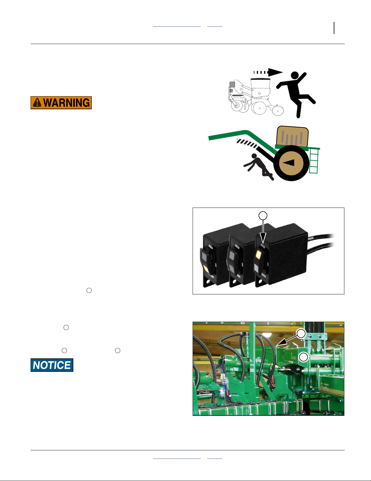
Refer to Figure 11
3. Set Hydraulic Selector Marker/Fold switch to
“FOLD” to enable fold cylinder hydraulics.
4. Activate lift hydraulics. Raise planter until lift
hydraulics are fully raised. This raises the wing
frames above the hooks .
Planter Damage Risk:
Be sure planter’s lift hydraulics are fully raised before
unfolding or frame and/or hook damage WILL occur.
F
6 5
5
Figure 11
Hydraulic Selector Switch
34552
5
6
Figure 12
Transport Hook
2012-12-27 Table of Contents Index 401-832M
34571
24 YP1630F Table of Contents Index Great Plains Manufacturing, Inc.
Release Wing Locks
Refer to Figure 13
A pair of inverted hooks on the tongue tube engage
8
locks on each wing when the planter is folded.
Prior to unfolding, this lock system must be released by
raising the tongue. Raise the 3-point hitch to disengage
the wing lock.
7
7
Re-Phase Fold Cylinders
5. The fold system uses re-phasing cylinders. It is
necessary to re-phase cylinders so wing gauge
wheels run in their fully rotated positions in front of
planter. To re-phase fold cylinders:
Move and hold lever for Marker/Fold in Fold direction
(typically Extend) for 30 seconds. This causes wings
to push against the tongue transport hooks .
7
Partially Unfold
Refer to Figure 13
6. Reverse fold circuit lever until wings clear transport
hooks by a few feet.
7
Lower Tongue
7. Lower 3-point hitch or hydraulic tongue to planting
position. See page 19 and page 123 for correct hitch
height and depth control settings.
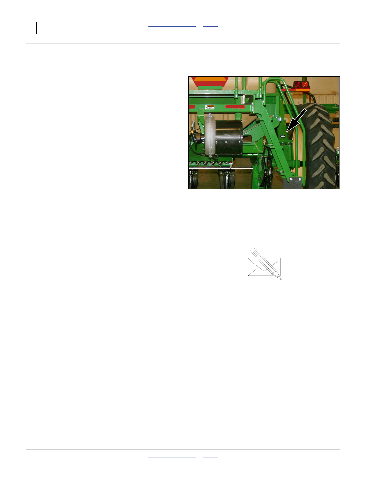
Fully Unfold
Refer to Figure 14
8. Unfold the planter fully to planting position. Unfolding
is complete when the large roller bushing on top of
the tongue is engaged by the tongue safety latch .
9
8
Figure 13
Wing Hook & Wing Lock
9
22815
27288
Planter Damage Risk:
Do not plant if the tongue latch is not fully down over the
roller. Frame and opener damage is likely if the planter is
operated with the latch open.
401-832M Table of Contents Index 2012-12-27
Figure 14
Tongue Latch Engaged
28488
Great Plains Manufacturing, Inc. Table of Contents Index Operating Instructions 25
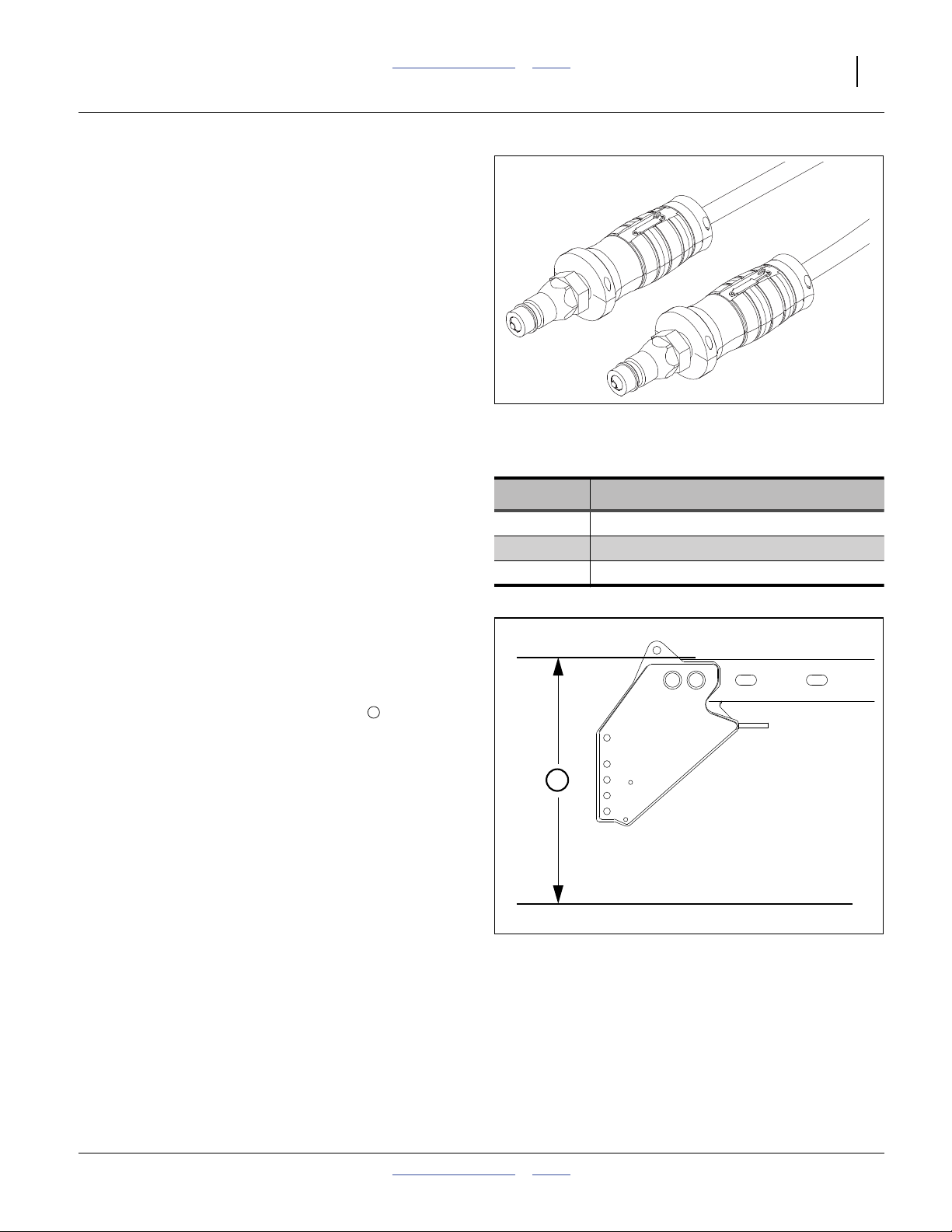
Remove and Store Transport Locks
The planter needs to still be in full lift to remove these
locks.
Remove/Store Center Lift Locks
Refer to Figure 15
9. Remove lock channels from vertical cylinders
above pivots.
1
2
2
1
Refer to Figure 15 and Figure 16
10. Store lock channels horizontally on tubes at sides
of lift cylinder weldment.
2
Figure 15
Frame Lift Locks Installed
2
Figure 16
Lift Cylinder Lock Stored
34550
34549
2012-12-27 Table of Contents Index 401-832M

26 YP1630F Table of Contents Index Great Plains Manufacturing, Inc.
Remove/Store Caster Lift Locks
Refer to Figure 17
11. Remove transport lock channels from lift cylinders
located on gauge wheels.
Refer to Figure 17 and Figure 18
12. Transfer lift cylinder transport lock channels to
their storage positions .
4
3
3
3
Unfold Closeout
13. As appropriate for the next planned activity, activate
lift hydraulics and lower planter.
14. To disable fold hydraulics, and lock caster arms in
field position, set Hydraulic Selector Marker/Fold
switch ( or in Figure 19 on page 27) to center/off
or Marker.
Note: The center/off switch position disables all
M O
Fold/Marker solenoid valves.
4
Figure 17
Caster Lift Cylinder Lock
34550
3
4
Figure 18
Transport Cylinder Lock Storage
27290
401-832M Table of Contents Index 2012-12-27
 Loading...