

Page 1
Table of Contents Index
Operator
YP1225A & YP1625A
30- and 40-Foot 2-Section Yield-Pro® Planters
®
with Air-Pro
Manufacturing, Inc.
www.greatplainsmfg.com
Seed Meters
Read the operator manual entirely. When you see this symbol, the
subsequent instructions and warnings are serious - follow without
exception. Your life and the lives of others depend on it!
29618
Illustrations may show optional equipment not supplied with standard unit or may
depict similar YP1225 or YP1625 models where a topic is identical.
ORIGINAL INSTRUCTIONS
© Copyright 2012 Printed 2013-08-13 401-625M
Table of Contents Index
EN
Page 2

Table of Contents Index
Table of Contents Index
Page 3

Great Plains Manufacturing, Inc. Cover Index iii
Table of Contents
Important Safety Information ......................................1
Safety Decals .................................................................6
Introduction ................................................................11
Description of Unit ........................................................11
Intended Usage ........................................................11
Document Family .........................................................11
Covered Models ...........................................................11
Using This Manual........................................................11
Definitions................................................................. 12
Owner Assistance ........................................................12
Preparation and Setup ...............................................13
Initial Setup...................................................................13
Pre-Planting Setup .......................................................13
Hitching Tractor to Planter............................................14
Hydraulic Hookup .....................................................14
Hydraulic Hose Hookup............................................ 14
Protecting Hydraulic Motor Seals ............................. 15
3-Point Hitch.............................................................16
Hitching with Hydraulic Tongue (Option)..................16
Raising/Lowering Tongue......................................... 17
Hitching with Either Hitch..........................................17
Electrical Hookup......................................................17
Store Main Parking Stand.........................................18
Lock Up Fertilizer Drive ............................................ 18
Operating Instructions...............................................19
Pre-Start Checklist .......................................................19
Wing Lock Overview.....................................................19
Unfolding The Planter...................................................20
Prepare Hitched Tractor and Planter........................ 20
Prepare Transport Hooks ......................................... 20
Release Wing Locks................................................. 21
Re-Phase Fold Cylinders..........................................21
Partially Unfold .........................................................21
Lower Tongue ..........................................................21
Fully Unfold ..............................................................22
Remove and Store Transport Locks......................... 22
Unfold Closeout........................................................23
Raising/Lowering Planter .............................................24
Raising Planter .........................................................24
Lowering Planter ......................................................24
Re-phasing Lift System ............................................25
Folding the Planter .......................................................25
Shut off Fan and Hydraulic Drive..............................26
Set Tractor and Tongue ...........................................26
Raise Planter............................................................ 26
Install Lock Channels ............................................... 26
Activate Fold Solenoid Valves.................................. 27
Begin Folding ........................................................... 27
Raise Tongue...........................................................27
Complete Fold..........................................................27
Lower Tongue .......................................................... 27
Re-phasing Fold System.......................................... 27
Transporting................................................................. 28
Loading Materials......................................................... 29
Material Loading Overview....................................... 29
Mounting a Hopper or Bulk Seed Box...................... 29
Loading Hopper with Seed.......................................32
Using Auxiliary Hydraulic Circuit ..........................32
Dismounting a Hopper or Seed Box......................... 34
Fertilizer Tanks (Option) .............................................. 35
Filling Tanks ............................................................. 35
Ground Drive Pump ................................................. 35
Field Setup Checklist ................................................... 36
Monitor Operation ........................................................ 37
Electric Clutch Operation ............................................. 38
Hydraulic Drive Operation (Option).............................. 39
Air System Operation................................................... 40
Air System Overview................................................ 41
Fan Circuit Operation ........................................... 42
Fan General Operating Information ..................... 43
Recommended Initial Fan Speeds ....................... 43
Marker Operation ......................................................... 44
Field Operation ............................................................ 45
Skip and Double Checks...................................... 45
Parking......................................................................... 46
Storage ........................................................................ 47
Storage: Fertilizer Option ......................................... 47
Adjustments ............................................................... 48
Setting Material Rates.................................................. 49
Planting Rate............................................................ 49
Fan and Meter Pressurization Adjustment................... 51
Fill Disk with Ground Drive:.................................. 51
Furrow Check:...................................................... 52
Fine-Tuning Meter Pressurization ............................ 53
Checking Planting Rate ............................................... 54
Checking Singulated Rate........................................ 54
Setting Fertilizer Rate .................................................. 55
Marker Adjustments ..................................................... 56
Dual Marker Speed Adjustment ............................... 56
© Copyright 2005, 2006, 2007, 2008, 2009, 2010, 2011, 2012 All rights Reserved
Great Plains Manufacturing, Inc. provides this publication “as is” without warranty of any kind, either expressed or implied. While every precaution has been
taken in the preparation of this manual, Great Plains Manufacturing, Inc. assumes no responsibility for errors or omissions. Neither is any liability assumed for
damages resulting from the use of the information contained herein. Great Plains Manufacturing, Inc. reserves the right to revise and improve its products as
it sees fit. This publication describes the state of this product at the time of its publication, and may not reflect the product in the future.
2013-08-13 Cover Index 195-325M
Trademarks of Great Plains Manufacturing, Inc. include: Singulator Plus, Swath Command, Terra-Tine.
Registered Trademarks of Great Plains Manufacturing, Inc. include:
Air-Pro, Clear-Shot, Discovator, Great Plains, Land Pride, MeterCone, Nutri-Pro, Seed-Lok, Solid Stand,
Terra-Guard, Turbo-Chisel, Turbo-Chopper, Turbo Max, Turbo-Till, Ultra-Till, Ver ti-Till, Whirlfilter, Yield-Pro.
Brand and Product Names that appear and are owned by others are trademarks of their respective owners.
Printed in the United States of America
Page 4

iv YP1125A & YP1625A Table of Contents Index Great Plains Manufacturing, Inc.
Marker Disk Adjustment........................................... 56
Height Switch ............................................................... 57
Row Implement Adjustments ....................................... 58
Frame-Mounted Row Accessories........................... 58
Terra-Tine™ Adjustment...................................... 58
Frame-Mounted Coulters ..................................... 59
Vantage I Applicator............................................. 59
25 Series Row-Unit Adjustments ................................. 60
Row-Unit Down Pressure......................................... 61
Spring Down Pressure ......................................... 61
Unit-Mount Cleaner Adjustments ............................. 63
Unit-Mounted Coulter Adjustments .......................... 64
Row-Unit Opener Disc Adjustments......................... 65
Setting Planting Depth ......................................... 65
Side Gauge Wheel Adjustments .............................. 66
Adjusting Gauge Wheel Scrapers............................ 67
Meter Adjustments ................................................... 68
Meter Rain Cover ................................................. 68
Seed Inlet Shutter Adjustment ............................. 68
Optimal Seed Pool Slopes ................................... 69
Meter Re-Fill......................................................... 69
Air-Pro® Meter Disk Installation ............................... 70
Removing a Seed Disk......................................... 71
Row Unit Shut-Off .................................................... 71
Seed Firmer Adjustments ........................................ 74
Keeton® Seed Firmer Adjustment........................ 74
Seed-Lok® Seed Firmer Lock-Up ........................ 75
Seed-Lok® Seed Firmer Lock-Up (older style)..... 75
Press Wheel Adjustments........................................ 76
Press Wheel Centering ........................................ 76
Troubleshooting......................................................... 77
Planting Rate Problems ............................................... 77
Suggested Furrow Check:.................................... 77
Seed Pool Troubleshooting.......................................... 78
Seed Pool Recovery ................................................ 79
Population Troubleshooting Charts.............................. 79
Maintenance and Lubrication ................................... 88
Maintenance ................................................................ 88
Tongue Lift Cylinder Locks ...................................... 89
Material Clean-Out....................................................... 90
Hopper Clean-Out.................................................... 90
Air System Clean-Out .............................................. 91
Meter Clean-Out ...................................................... 92
Funnel Conversion ............................................... 92
Alternate Meter Clean-Out ................................... 93
Seed Tube Clean-Out .......................................... 93
Meter Brush Maintenance............................................ 94
Meter Brush Replacement ....................................... 95
Seed Disk Maintenance............................................96
Cleaning and Storing Seed Disks .........................96
Bleeding Hydraulics......................................................97
Bleeding Lift Hydraulics ............................................97
Bleeding Fold Cylinder Hydraulics............................97
Bleeding Marker Hydraulics......................................98
Marker Maintenance.....................................................98
Hydraulic Drive Maintenance........................................99
Chain Maintenance.....................................................100
Meter Drive Chain.......................................................100
Disc Spreaders and Scrapers.....................................101
25 Series Row-Unit Side Wheels............................101
Fertilizer System Maintenance ...................................102
Liquid Fertilizer Strainer..........................................102
Seed Flap Replacement .............................................103
Lubrication ..................................................................104
Seed Lubricant ...........................................................111
Options and Accessories ........................................112
Appendix A - Reference Information ......................124
Specifications and Capacities.....................................124
YP1225 Models ......................................................124
YP1625 North America Models ..............................125
YP1625 Export Model.............................................126
Tire Inflation Chart ......................................................127
Hydraulic Diagrams ....................................................128
Chain Routing.............................................................137
Torque Values Chart ..................................................140
Appendix B - Pre-Delivery .......................................141
Appendix C - Initial Setup ........................................146
Hydraulic Charge and Bleed.......................................146
Console Installation ....................................................146
Monitor Setup .........................................................146
YP1225A Row Spacing Setup Data ...................146
YP1625A Row Spacing Setup Data ...................146
Level Planter...............................................................147
Wing Alignment ..........................................................148
Speed Calibration .......................................................149
Speed Sensor Operation ........................................149
Marker Setup ..............................................................150
Marker Extension....................................................150
Appendix D - Option Installation.............................151
122-278S Scraper Installation ....................................151
Appendix R - Row Pro..............................................152
Warranty .....................................................................159
Index ..........................................................................161
195-325M Table of Contents Index 2013-08-13
Page 5
Great Plains Manufacturing, Inc. Table of Contents Index 1
Important Safety Information
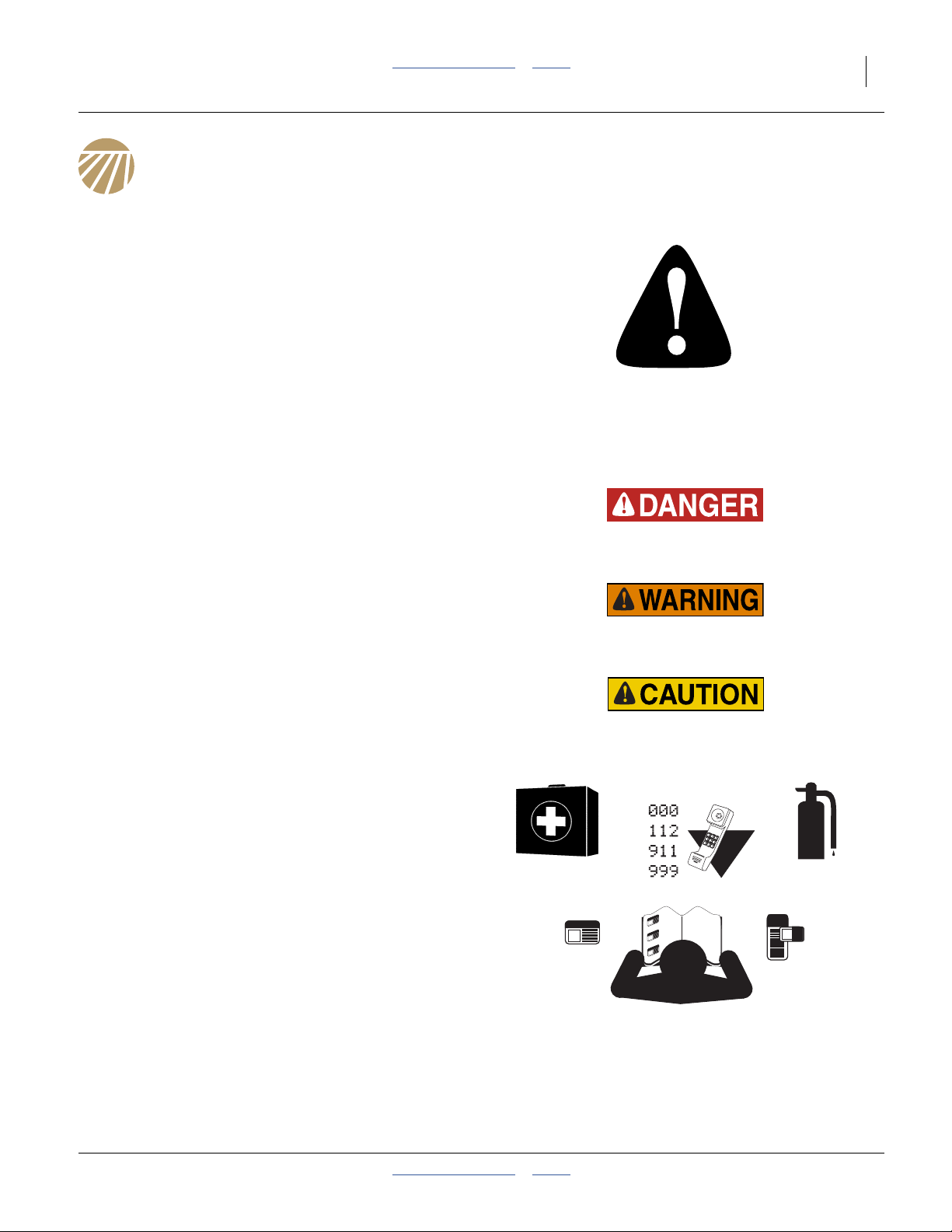
Look for Safety Symbol
The SAFETY ALERT SYMBOL indicates there is a
potential hazard to personal safety involved and extra
safety precaution must be taken. When you see this
symbol, be alert and carefully read the message that
follows it. In addition to design and configuration of
equipment, hazard control and accident prevention are
dependent upon the awareness, concern, prudence and
proper training of personnel involved in the operation,
transport, maintenance and storage of equipment.
Be Aware of Signal Words
Signal words designate a degree or level of hazard
seriousness.
DANGER indicates an imminently hazardous situation
which, if not avoided, will result in death or serious injury.
This signal word is limited to the most extreme situations,
typically for machine components that, for functional
purposes, cannot be guarded.
WARNING indicates a potentially hazardous situation
which, if not avoided, could result in death or serious
injury, and includes hazards that are exposed when
guards are removed. It may also be used to alert against
unsafe practices.
CAUTION indicates a potentially hazardous situation
which, if not avoided, may result in minor or moderate
injury. It may also be used to alert against unsafe
practices.
Prepare for Emergencies
▲ Be prepared if a fire starts
▲ Keep a first aid kit and fire extinguisher handy.
▲ Keep emergency numbers for doctor, ambulance, hospital
and fire department near phone.
Be Familiar with Safety Decals
▲ Read and understand “Safety Decals” on page 6,
thoroughly.
▲ Read all instructions noted on the decals.
▲ Keep decals clean. Replace damaged, faded and illegible
decals.
2013-08-13 Table of Contents Index 401-625M
Page 6

2 YP1125A & YP1625A Table of Contents Index Great Plains Manufacturing, Inc.
Wear Protective Equipment
Great Plains advises all users of chemical pesticides or
herbicides to use the following personal safety
equipment.
▲ Waterproof, wide-brimmed hat
▲ Waterproof apron.
▲ Face shield, goggles or full face respirator.
▲ Goggles with side shields or a full face respirator is
required if handling or applying dusts, wettable powders, or
granules or if being exposed to spray mist.
▲ Cartridge-type respirator approved for pesticide vapors
unless label specifies another type of respirator.
▲ Waterproof, unlined gloves. Neoprene gloves are
recommended.
▲ Cloth coveralls/outer clothing changed daily; waterproof
items if there is a chance of becoming wet with spray
▲ Waterproof boots or foot coverings
▲ Do not wear contaminated clothing. Wash protective
clothing and equipment with soap and water after each use.
Personal clothing must be laundered separately from
household articles.
▲ Clothing contaminated with certain pesticides must be
destroyed according to state and local regulations. Read
chemical label for specific instructions.
▲ Wear clothing and equipment appropriate for the job. Avoid
loose-fitting clothing.
▲ Prolonged exposure to loud noise can cause hearing
impairment or loss. Wear suitable hearing protection such
as earmuffs or earplugs.
▲ Avoid wearing entertainment headphones while operating
machinery. Operating equipment safely requires the full
attention of the operator.
Use A Safety Chain (Hydraulic Hitch)
▲ Use a safety chain to help control drawn machinery should
it separate from tractor draw bar.
▲ Use a chain with a strength rating equal to or greater than
the gross weight of towed machinery.
▲ Attach chain to tractor draw bar support or other specified
anchor location. Allow only enough slack to permit turning.
▲ Replace chain if any links or end fittings are broken,
stretched or damaged.
▲ Do not use safety chain for towing.
401-625M Table of Contents Index 2013-08-13
Page 7

Great Plains Manufacturing, Inc. Table of Contents Index Important Safety Information 3
Avoid High Pressure Fluids
Escaping fluid under pressure can penetrate the skin,
causing serious injury.
▲ Avoid the hazard by relieving pressure before disconnecting
hydraulic lines.
▲ Use a piece of paper or cardboard, NOT BODY PARTS, to
check for suspected leaks.
▲ Wear protective gloves and safety glasses or goggles when
working with hydraulic systems.
▲ If an accident occurs, seek immediate medical assistance
from a physician familiar with this type of injury.
Handle Chemicals Properly
▲ Read and follow chemical manufacturer’s instructions.
▲ Wear protective clothing.
▲ Handle all chemicals with care.
▲ Agricultural chemicals can be dangerous. Improper use can
seriously injure persons, animals, plants, soil and property.
▲ Inhaling smoke from any type of chemical fire is a serious
health hazard.
▲ Store or dispose of unused chemicals as specified by the
chemical manufacturer.
▲ Before adding chemical to the tank, make sure tank is at
least half full. Do not pour concentrate into an empty tank.
▲ Never leave fill hose attached to the sprayer after filling
tank. Chemicals in tank can siphon out of tank and
contaminate freshwater source.
▲ Immediately and thoroughly flush any area of the body that
is contaminated by chemicals.
▲ Do not touch plumbing components with mouth or lips.
▲ If chemical is swallowed, carefully follow the chemical
manufacturer’s recommendations and consult with a doctor.
▲ If persons are exposed to a chemical in a way that could
affect their health, consult a doctor immediately with the
chemical label or container in hand. Any delay could cause
serious illness or death.
▲ Dispose of empty chemical containers properly. By law
rinsing of the used chemical container must be repeated
three times. Puncture the container to prevent future use. An
alternative is to jet-rinse or pressure rinse the container.
▲ After working with chemicals, wash hands and face before
eating. Shower when application is completed for the day.
▲ Never wash out the tanks within 100 feet (30m) of any
freshwater source or in a car wash.
▲ Rinse out the tank. Apply rinse water on last field treated.
Keep Riders Off Machinery
Riders obstruct the operator’s view. Riders could be
struck by foreign objects or thrown from the machine.
▲ Never allow children to operate equipment.
▲ Keep all bystanders away from machine during operation.
2013-08-13 Table of Contents Index 401-625M
Page 8
4 YP1125A & YP1625A Table of Contents Index Great Plains Manufacturing, Inc.
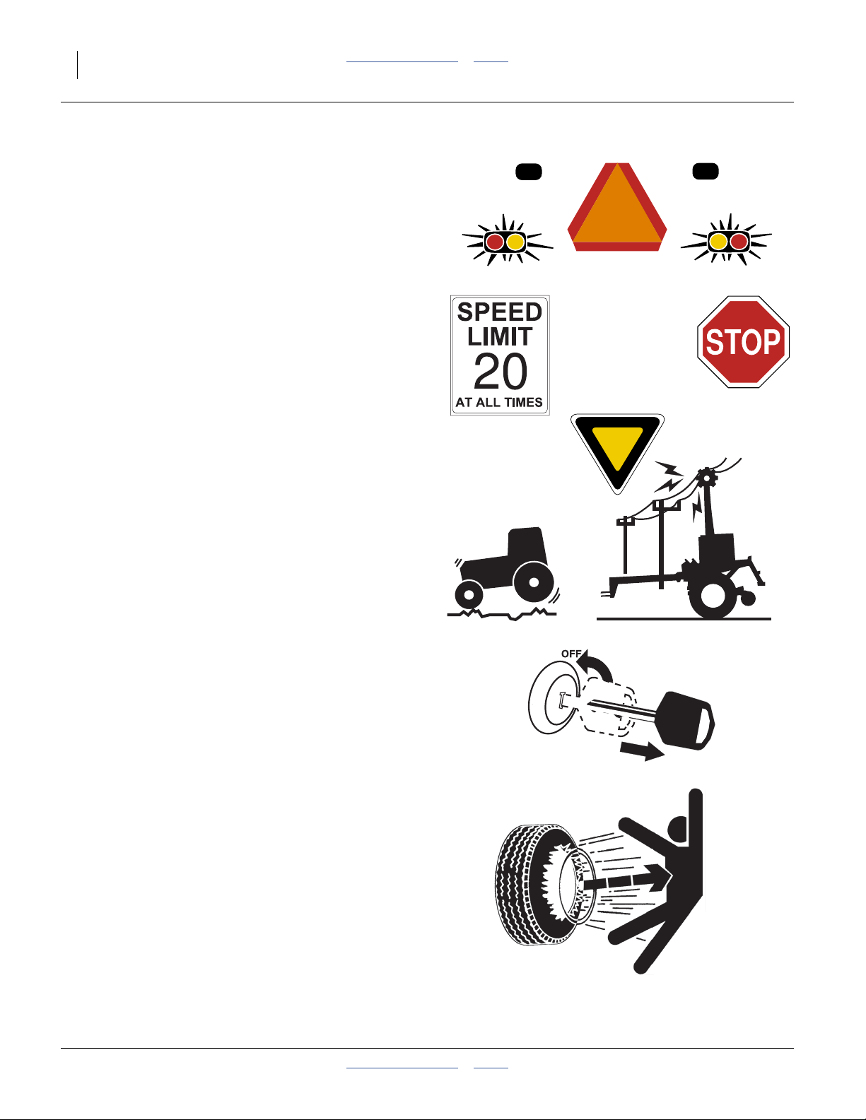
Use Safety Lights and Devices
Slow-moving tractors and towed implements can create
a hazard when driven on public roads. They are difficult
to see, especially at night.
▲ Use flashing warning lights and turn signals whenever
driving on public roads.
▲ Use lights and devices provided with implement
Transport Machinery Safely
Maximum transport speed for implement is 20 mph
(32 km/h). Some rough terrains require a slower speed.
Sudden braking can cause a towed load to swerve and
upset.
▲ Do not exceed 20 mph (32 km/h). Never travel speeds which
do not allow adequate control of steering and stopping.
Reduce speed if towed load is not equipped with brakes.
▲ Comply with state and local laws.
▲ Do not tow an implement that, when fully loaded, weighs
more than 1.5 times the weight of towing vehicle.
▲ Carry reflectors or flags to mark planter in case of
breakdown on the road.
▲ Keep clear of overhead power lines and other obstructions
when transporting. Refer to transport dimensions under
“Specifications and Capacities” on page 124.
▲ Do not fold or unfold the planter while the tractor is
moving.
Shutdown and Storage
▲ Lower planter, put tractor in park, turn off engine, and
remove the key.
▲ Secure planter using blocks and supports provided.
▲ Detach and store planter in an area where children
normally do not play.
Tire Safety
Tire changing can be dangerous and should be
performed by trained personnel using correct tools and
equipment.
▲ When inflating tires, use a clip-on chuck and extension hose
long enough for you to stand to one side–not in front of or
over tire assembly. Use a safety cage if available.
▲ When removing and installing wheels, use wheel-handling
equipment adequate for weight involved.
401-625M Table of Contents Index 2013-08-13
Page 9
Great Plains Manufacturing, Inc. Table of Contents Index Important Safety Information 5
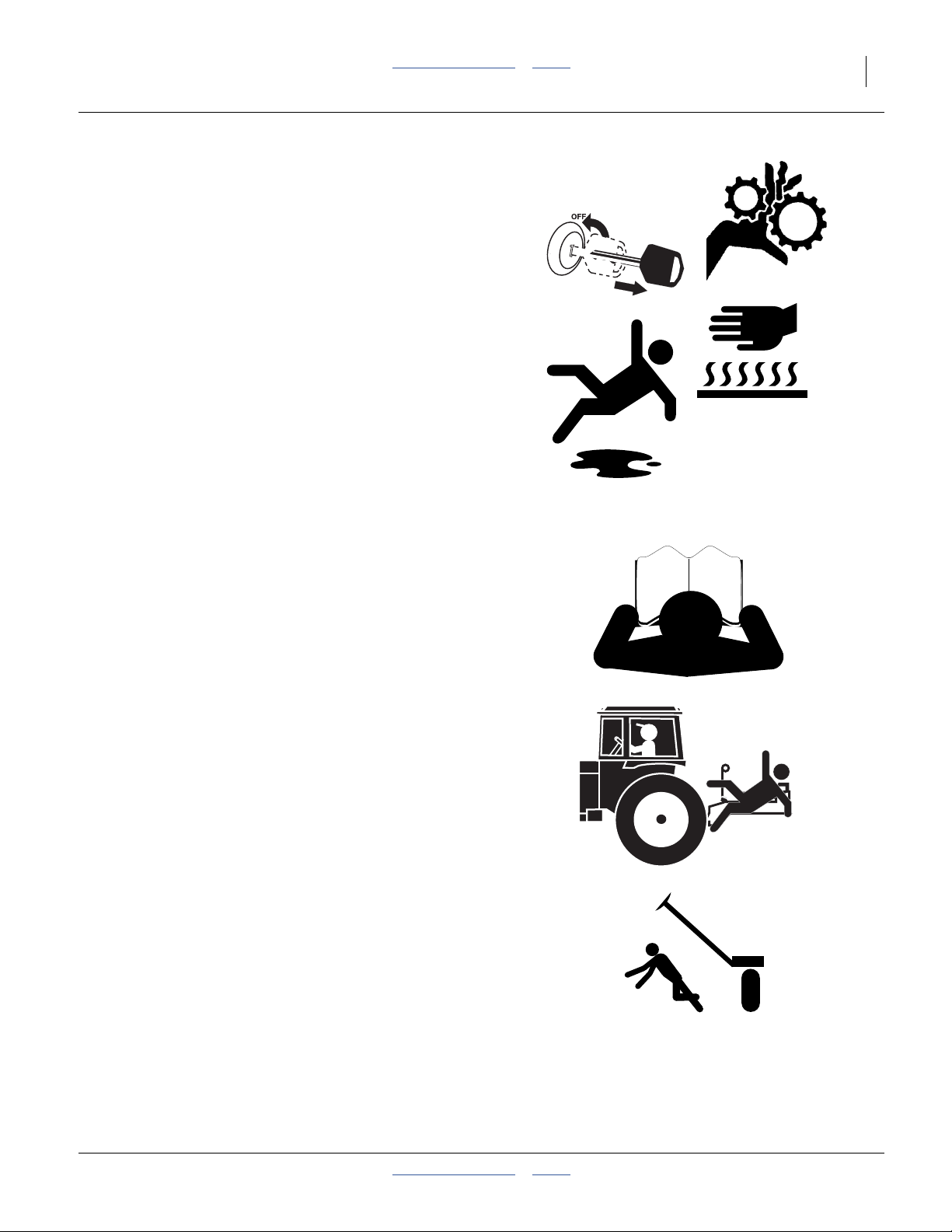
Practice Safe Maintenance
▲ Understand procedure before doing work. Use proper tools
and equipment. Refer to this manual for additional
information.
▲ Work in a clean, dry area.
▲ Lower the planter, put tractor in park, turn off engine, and
remove key before performing maintenance.
▲ Make sure all moving parts have stopped and all system
pressure is relieved.
▲ Allow planter to cool completely.
▲ Disconnect battery ground cable (-) before servicing or
adjusting electrical systems or before welding on planter.
▲ Inspect all parts. Make sure parts are in good condition and
installed properly.
▲ Remove buildup of grease, oil or debris.
▲ Remove all tools and unused parts from planter before
operation.
Safety At All Times
Thoroughly read and understand the instructions in this
manual before operation. Read all instructions noted on
the safety decals.
▲ Be familiar with all planter functions.
▲ Operate machinery from the driver’s seat only.
▲ Do not leave planter unattended with tractor engine
running.
▲ Do not dismount a moving tractor. Dismounting a moving
tractor could cause serious injury or death.
▲ Do not stand between the tractor and planter during
hitching.
▲ Keep hands, feet and clothing away from power-driven
parts.
▲ Wear snug-fitting clothing to avoid entanglement with
moving parts.
▲ Watch out for wires, trees, etc., when folding and raising
planter. Make sure all persons are clear of working area.
2013-08-13 Table of Contents Index 401-625M
Page 10
6 YP1125A & YP1625A Table of Contents Index Great Plains Manufacturing, Inc.
Safety Decals
Safety Reflectors and Decals
Your implement comes equipped with all lights, safety
reflectors and decals in place. They were designed to
help you safely operate your implement.
▲ Read and follow decal directions.
▲ Keep lights in operating condition.
▲ Keep all safety decals clean and legible.
▲ Replace all damaged or missing decals. Order new decals
from your Great Plains dealer. Refer to this section for
proper decal placement.
▲ When ordering new parts or components, also request
corresponding safety decals.
To install new decals:
1. Clean the area on which the decal is to be placed.
2. Peel backing from decal. Press firmly on surface,
being careful not to cause air bubbles under decal.
818-055C
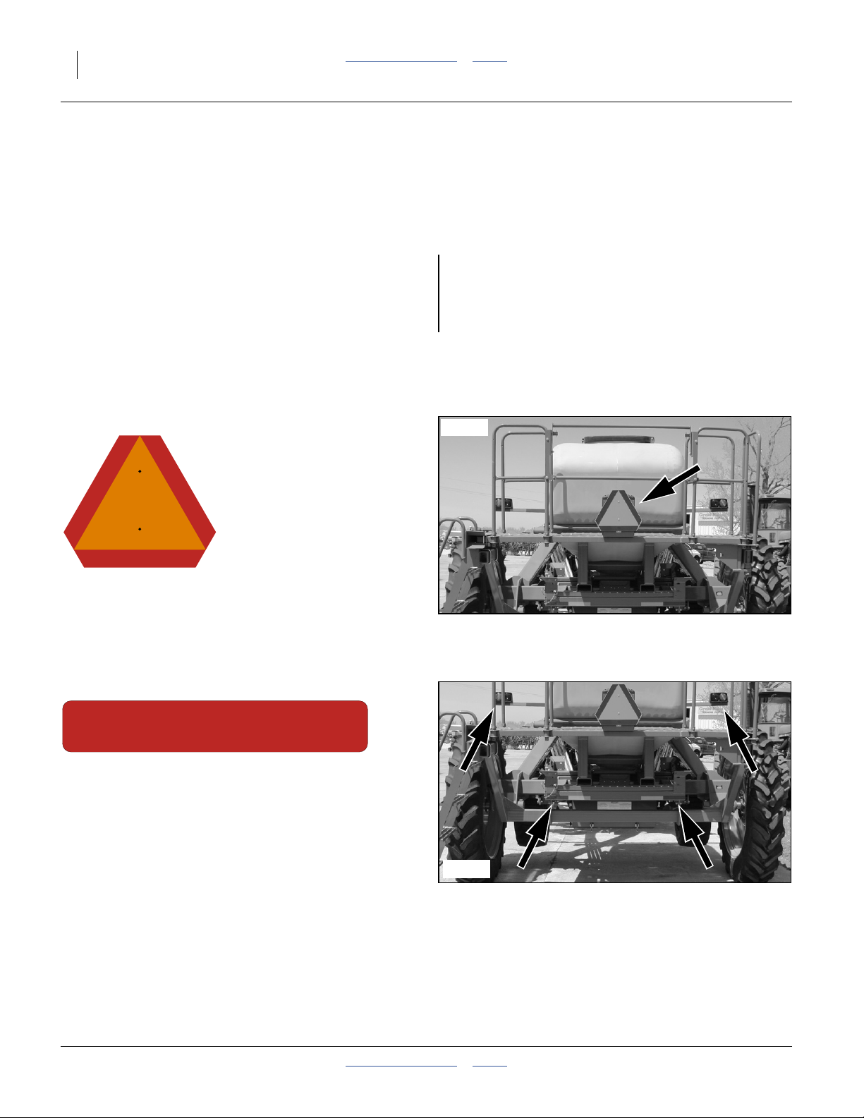
Slow Moving Vehicle Reflector
On the back of the planter, walkboard center;
1 total
See “Transporting” on page 28.
838-266C
Red Reflectors
On the back of seed frame each end,
and on the rear face of each light mounting bar;
4 total
29503
29503
401-625M Table of Contents Index 2013-08-13
Page 11
Great Plains Manufacturing, Inc. Table of Contents Index Important Safety Information 7
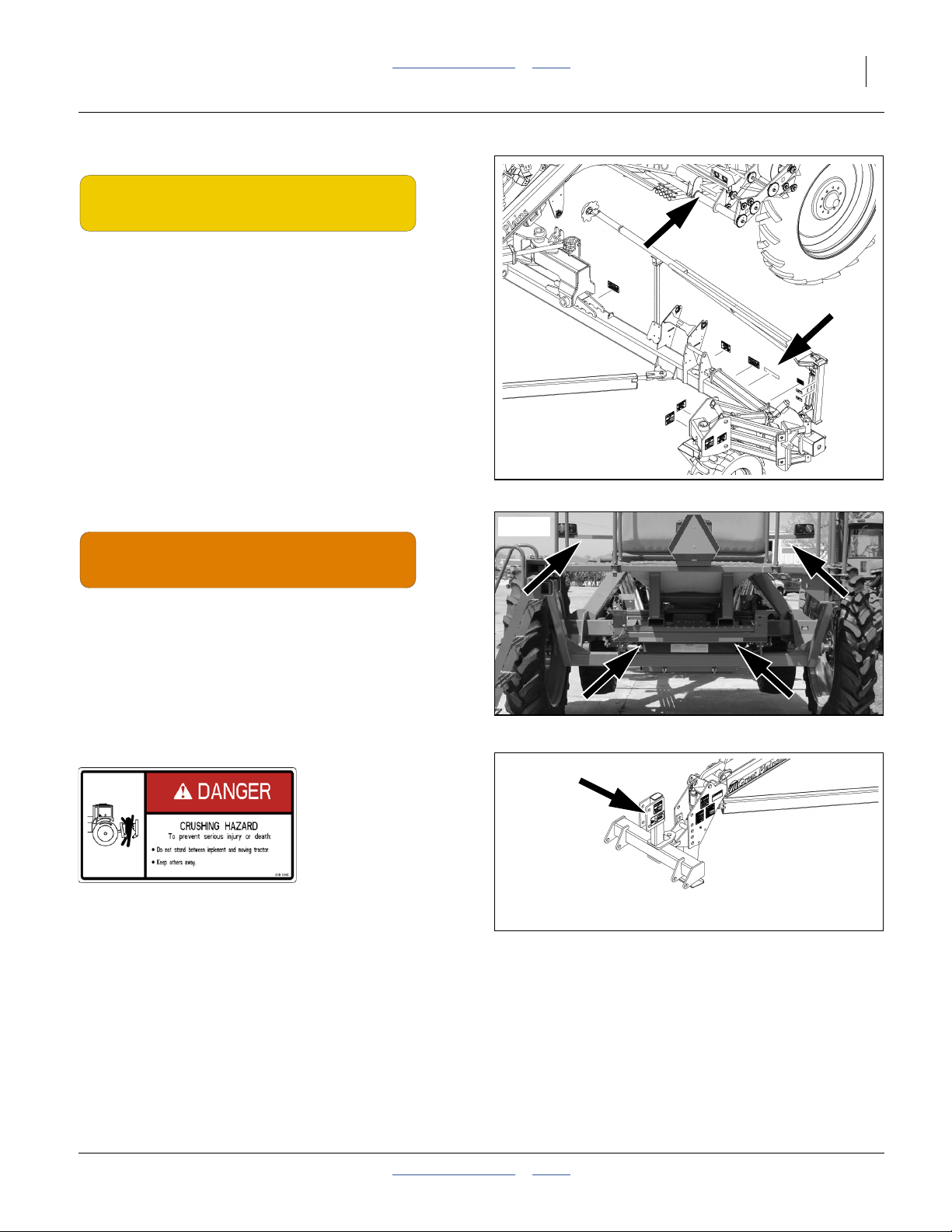
838-265C
Amber Reflectors
One each on rear face of wing tool bar at wing lock,
one each on front face of light bars;
4 total
29622
838-267C
Daytime Reflectors
On the back of seed frame, inside red reflectors,
on the rear face of the light bar;
4 total
818-590C
Danger: Crushing Hazard
On the hitch, one total.
See “Hitching Tractor to Planter” on page 14.
29503
29622
2013-08-13 Table of Contents Index 401-625M
Page 12
8 YP1125A & YP1625A Table of Contents Index Great Plains Manufacturing, Inc.
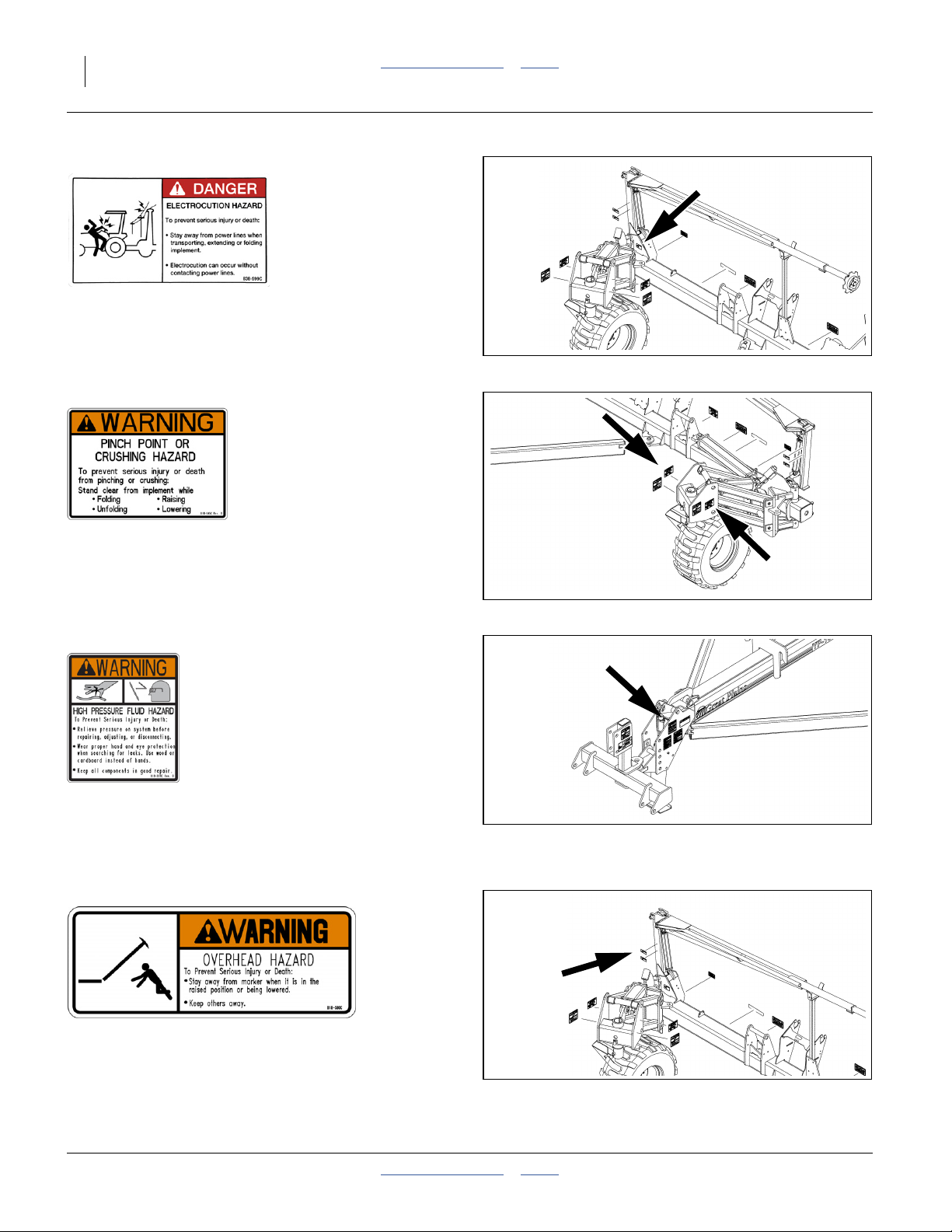
838-599C (Option)
Danger: Electrocution Hazard
On marker section each end, two total.
See “Marker Operation” on page 44.
29622
818-045C
Warning: Pinch-Crush
Above both tires, two total
818-339C
Warning: High Pressure Fluid Hazard
On the tongue, one total
See “Hydraulic Hose Hookup” on page 14.
818-580C (Option)
29622
29622
Warning: Overhead Hazard
On marker section each end, two total
See “Marker Operation” on page 44.
401-625M Table of Contents Index 2013-08-13
29622
Page 13
Great Plains Manufacturing, Inc. Table of Contents Index Important Safety Information 9
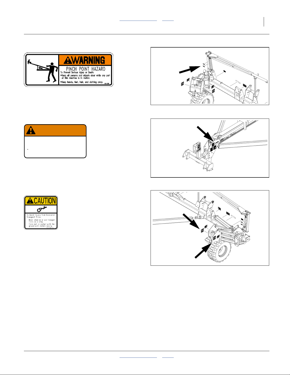
818-579C (Option)
Warning: Pinch-Shear Hazard
On marker section each end, two total
See “Marker Operation” on page 44.
29622
818-188C
WARNING
EXCESSIVE SPEED HAZARD
To Prevent Serious Injury or Death:
Do Not exceed 20 mph maximum transport
speed. Loss of vehicle control and/or machine
can result.
Warning: Excessive Speed
On the tongue, one total
See “Transporting” on page 28.
818-188C Rev. C
29622
818-398C
Caution: Tires Not A Step
Above both tires, two total
In transport configuration, wing gauge wheels are off the
ground and free to spin. In field configuration, at higher
row unit down-forces, wing gauge wheels may have little
or no ground traction.
29622
2013-08-13 Table of Contents Index 401-625M
Page 14
10 YP1125A & YP1625A Table of Contents Index Great Plains Manufacturing, Inc.
818-578C
CAUTION
To Avoid Injury or Machine Damage from improper Tire
Inflation or Torquing of Wheel Bolts:
Maximum inflation pressure of tires is 65 psi.
Torque wheel bolts to 240 lb-ft.
Caution: Tire Pressure
On hubcap side rim of each gauge wheel;
2 total
838-995C
818-578C
34547
Caution: General
On right side of hitch;
1 total
858-011C
CAUTION
To Avoid Injur y or Machine Damage from Improper Tire
Inflation or Torquing of Wheel Bolts:
Maximum inflation pressure of tires is 49 psi (338 kPa).
Torque wheel bolts to 315 ft-lb (427 N-m).
Warning: Tire Pressure
On outside rim of each main transport wheel;
2 total
858-011C
29622
34548
401-625M Table of Contents Index 2013-08-13
Page 15
Great Plains Manufacturing, Inc. Table of Contents Index 11
Introduction
Great Plains welcomes you to its growing family of new
product owners. This planter has been designed with
care and built by skilled workers using quality materials.
Proper setup, maintenance, and safe operating practices
will help you get years of satisfactory use.
Description of Unit
The 30- and 40-Foot 2-Section Yield-Pro® Planters are
pull-type planting implements for use in conventional till,
minimum-till, or light no-till conditions.
Yield-Pro® Planters have 25 Series, side-depth-control
row-units and Air-Pro
unit-mounted coulters are suitable for light to moderate
no-till conditions only. The planter folds for transport.
Intended Usage
Use the planter to seed production-agriculture crops
only. Do not modify the planter for use with attachments
other than Great Plains options and accessories
specified for use with the planter.
®
seed meters. Optional
R
Figure 1
Left/Right Convention
L
27281
Document Family Covered Models
401-625M Operator Manual (this manual)
401-625B Seed Rate Manual
401-625P Parts Manual
DICKEY-john®IntelliAg® manuals:
110011508 Planter/Drill Control, User Level 1
110011501 Planter/Drill Control, User Level 2&3
110011440 A1 & AI-100 10-inch Virtual Terminal
110011606 AI-120 12-inch Virtual Terminal
DICKEY-john® Quick Start Guides
110011526 YP1225A-1230 12 Row 30-Inch
110011591 YP1225A-1820 18 Row 20-Inch
110011590 YP1225A-2315 23 Row 15-Inch
110011592 YP1225A-24TR 24 Twin Row 30-Inch
110011593 YP1225A-16TR36 16 Twin Row 30-Inch
110011602 YP1625A-1236 12 Row 36-Inch
110011527 YP1625A-1630 16 Row 30-Inch
110011603 YP1625A-1670 16 Row 70 cm
110011601 YP1625A-2420 24 Row 20-Inch
110011605 YP1625A-24TR36 24 Twin Row 36-Inch
110011600 YP1625A-3115 31 Row 15-Inch
110011604 YP1625A-32TR 32 Twin Row 30-Inch
YP1225A-1230 30-Foot, 12-Row, 30-Inch
YP1225A-16TR36 30-Foot, 16-Row (8 Twin), 36-Inch
YP1225A-1820 30-Foot, 18-Row, 20-Inch
YP1225A-2315 30-Foot, 23-Row, 15-Inch
YP1225A-24TR 30-Foot, 24-Row, (12 Twin) 30-Inch
YP1625A-1236 40-Foot, 12-Row, 36-Inch
YP1625A-1630 40-Foot, 16-Row, 30-Inch
YP1625A-1670 12-Meter, 16-Row, 70cm
YP1625A-24TR36 40-Foot, 24-Row, 20-Inch
YP1625A-2420 40-Foot, 24-Row (12 Twin), 36-Inch
YP1625A-3115 40-Foot, 31-Row, 15-Inch
YP1625A-32TR 40-Foot, 32-Row (16 Twin), 30-Inch
Using This Manual
This manual familiarizes you with safety, assembly,
operation, adjustments, troubleshooting and
maintenance. Read this manual and follow the
recommendations to help ensure safe and efficient
operation.
The information in this manual is current at printing.
Some parts may change to assure top performance.
2013-08-13 Table of Contents Index 401-625M
Page 16
12 YP1125A & YP1625A Table of Contents Index Great Plains Manufacturing, Inc.
Definitions
The following terms are used throughout this manual.
Right-hand and left-hand as used in
this manual are determined by facing
the direction the machine will travel
while in use unless otherwise stated.
An orientation rose in some line art
illustrations shows the directions of:
Up, Back, Left, Down, Front, Right.
R
F
U
B
L
D
A crucial point of information related to the preceding topic.
Read and follow the directions provided before continuing, to
ensure safety, avoidance of machine damage, and to achieve
desired field results.
Note: Useful information related to the preceding topic.
Owner Assistance
If you need customer service or repair parts, contact a
Great Plains dealer. They have trained personnel, repair
parts, and equipment specially designed for Great Plains
products.
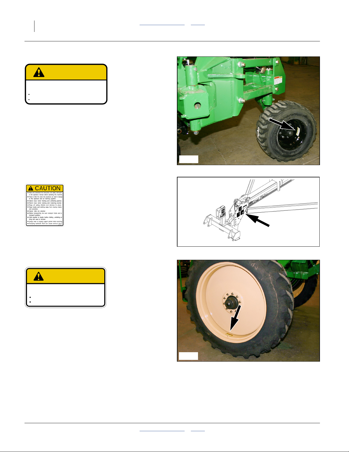
Refer to Figure 2
Your planter’s parts were specially designed and should
only be replaced with Great Plains parts. Always use the
serial and model number when ordering parts from your
Great Plains dealer. The serial-number plate is located
on the rear face of the right axle.
Record your Planter model and serial number here for
quick reference:
Model Number:__________________________
Serial Number: __________________________
Your Great Plains dealer wants you to be satisfied with
your new machine. If you do not understand any part of
this manual or are not satisfied with the service received,
please take the following actions.
1. Discuss the matter with your dealership service
manager. Make sure they are aware of any problems
so they can assist you.
2. If you are still unsatisfied, seek out the owner or
general manager of the dealership.
For further assistance write to:
U
L
B
F
R
D
Figure 2
Serial Number Plate
Product Support
Great Plains Mfg. Inc., Service Department
PO Box 5060
Salina, KS 67402-5060
27284
401-625M Table of Contents Index 2013-08-13
Page 17

Great Plains Manufacturing, Inc. Table of Contents Index 13
Preparation and Setup
This section helps you prepare your tractor and planter
for use. Before using the in the field, you must hitch the
planter to a suitable tractor and level the planter.
Initial Setup
If the planter has just been delivered, or broken down for
re-shipment, these items need to be completed prior to
first field use:
•“Hydraulic Charge and Bleed” on page 146, which
includes:
•“Console Installation” on page 146
•“Level Planter” on page 147, and
•“Marker Setup” on page 150.
You may also need to install features, options and
accessories that were not factory- or dealer-installed.
Pre-Planting Setup
The balance of this section covers items that need to be
completed or checked prior to each field use of the
planter.
1. Read and understand “Important Safety
Information” on page 1.
2. Check that all working parts are moving freely, bolts
are tight, and cotter pins are spread.
3. Check that all grease fittings are in place and
lubricated. See “Lubrication” on page 104.
4. Check that all safety decals and reflectors are
correctly located and legible. Replace if damaged.
See “Safety Decals” on page 6
5. Inflate tires to pressure recommended and tighten
wheel bolts as specified. See “Tire Inflation Chart”
on page 127.
6. If returning the planter to service from storage,
remove any grease used to protect cylinder rods.
2013-08-13 Table of Contents Index 401-625M
Page 18
14 YP1125A & YP1625A Table of Contents Index Great Plains Manufacturing, Inc.
Hitching Tractor to Planter
Crushing Hazard:
Do not stand or place any part of your body between planter
and moving tractor. You may be severely injured or killed by
being crushed between the tractor and planter. Stop tractor
engine and set park brake before attaching cables and hoses.
Hydraulic Hookup
High Pressure Fluid Hazard:
Relieve pressure before disconnecting hydraulic lines.
Escaping fluid under pressure can have sufficient pressure to
penetrate the skin causing serious injury. Use a piece of paper
or cardboard, NOT BODY PARTS, to check for leaks. Wear
protective gloves and safety glasses or goggles when working
with hydraulic systems. If an accident occurs, seek immediate
medical attention from a physician familiar with this type of
injury.
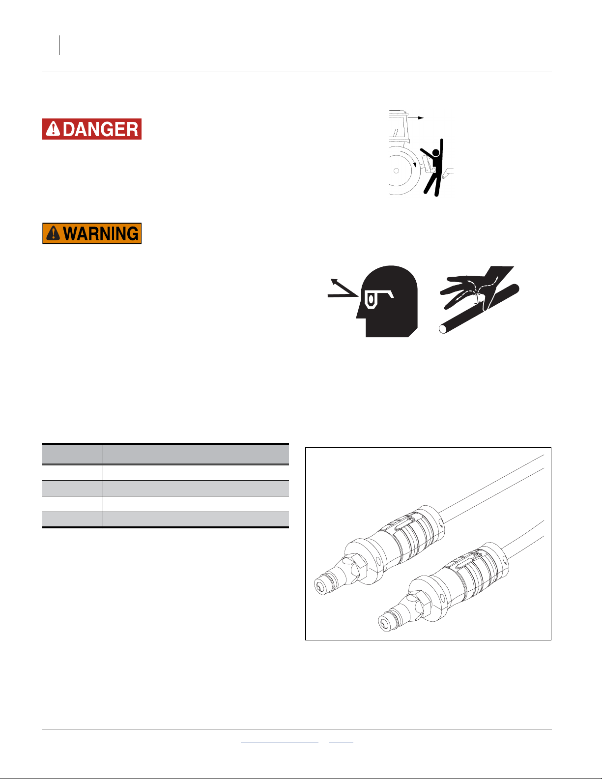
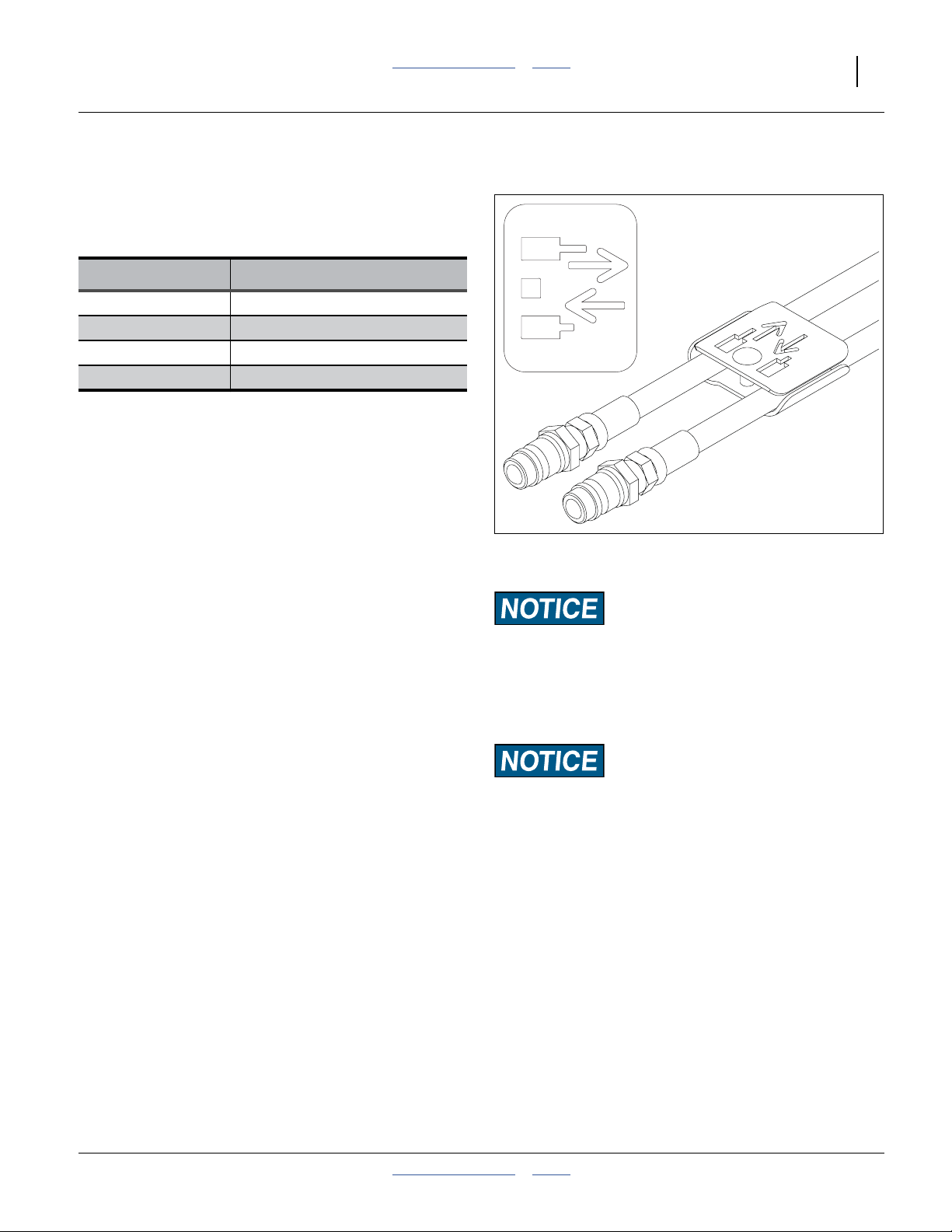
Hydraulic Hose Hookup
Refer to Figure 3
Great Plains hydraulic hoses have color coded handle
grips to help you hookup hoses to your tractor outlets.
Hoses that go to the same remote valve are marked with
the same color.
Current Style Color Coded Hose Handles
Color Hydraulic Function
Gray Fold/Marker
Blue Lift/Tongue
Black Fan
Yellow Hydraulic Drive (Option)
To distinguish hoses on the same hydraulic circuit, refer
to the symbol molded into the handle grip. Hoses with an
extended-cylinder symbol feed cylinder base ends.
Hoses with a retracted-cylinder symbol feed cylinder rod
ends.
For hydraulic fan and drive motors, connect the hose
under the retracted cylinder symbol to the pressure side
of the motor. Connect the hose under the extended
cylinder symbol to the return side of the motor.
The fan motor further requires hookup of a third line,
which returns hydraulic fluid from the fan motor case.
Figure 3
Color Coded Hose Handles
31733
401-625M Table of Contents Index 2013-08-13
Page 19
Great Plains Manufacturing, Inc. Table of Contents Index Preparation and Setup 15
Older Style Hoses with Color Ties
Refer to Figure 4
Great Plains hydraulic hoses are color coded. Hoses that
go to the same remote valve are marked with the same
color tie.
Color Hydraulic Function
White Fold/Marker
Blue Lift/Tongue
Orange Fan
Yellow Hydraulic Drive (Option)
To distinguish hoses on the same hydraulic circuit, refer
to plastic hose label. Hose under extended-cylinder
symbol feeds cylinder base ends. Hose under
retracted-cylinder symbol feeds cylinder rod ends.
Protecting Hydraulic Motor Seals
Low Pressure (Case) Drain Connection
7. Attach case drain hose to low pressure drain
connection.
8. Connect low pressure return hose to low pressure
return connector.
9. If the tractor has a limited number of remotes
capable of continuous flow, use them for the
hydraulic fan and optional hydraulic drive. (See
“Specifications and Capacities” on page 124 for
tractor requirements.)
Figure 4
Older Style Hoses w/Label
Motor Seal Damage Risk:
Case Drain Hose must be attached first,
prior to inlet and return hoses being connected.
Case Drain Hose must be detached last,
to prevent damage to the fan motor.
27270
Hydraulic Motor Performance Risk:
DO NOT hook case drain line to a “power-beyond port”.
2013-08-13 Table of Contents Index 401-625M
Page 20
16 YP1125A & YP1625A Table of Contents Index Great Plains Manufacturing, Inc.
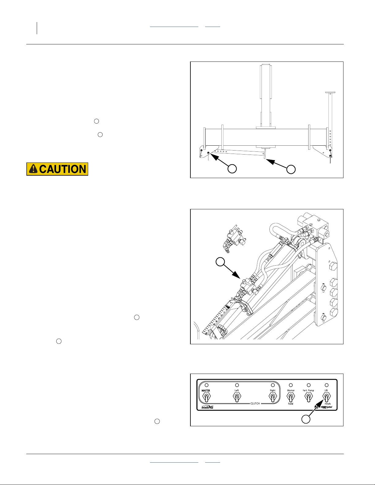
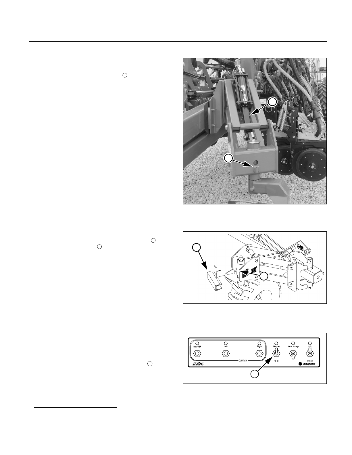
3-Point Hitch
Refer to Figure 5
10. Connect your tractor 3-point to the planter 3-point
hitch. If using quick hitch be sure planter locks into
hitch securely.
11. Raise tractor 3-point just enough to relieve pressure
off of the parking stand.
12. Store 3-point stands . There are two methods:
1
a. Remove lower pins . Swing stand under hitch.
Reinsert pin beneath stand at inner hole.
b. Remove both pins. Invert stand. Re-pin.
Load Sway Hazard:
Adjust 3-point hitch arms and sway blocks to minimize any
side-to-side sway to assure proper tracking in the field, and
safe road travel.
13. Connect hydraulic hoses to tractor remotes. See
“Hydraulic Hose Hookup” on page 14
2
Hitching with Hydraulic Tongue (Option)
Refer to Figure 6 (showing bypass valve closed)
1. Move the tractor to near hitching position.
2. Connect the hydraulic hoses for the tongue circuit.
This needs to be done before hitching in order to
raise and lower the tongue. See “Hydraulic Hose
Hookup” on page 14. Allow slack for hitch
movements. Close the tongue cylinder bypass valve.
3. Make electrical connections for at least the planter
monitor circuit (necessary to control planter hydraulic
systems). See page 17.
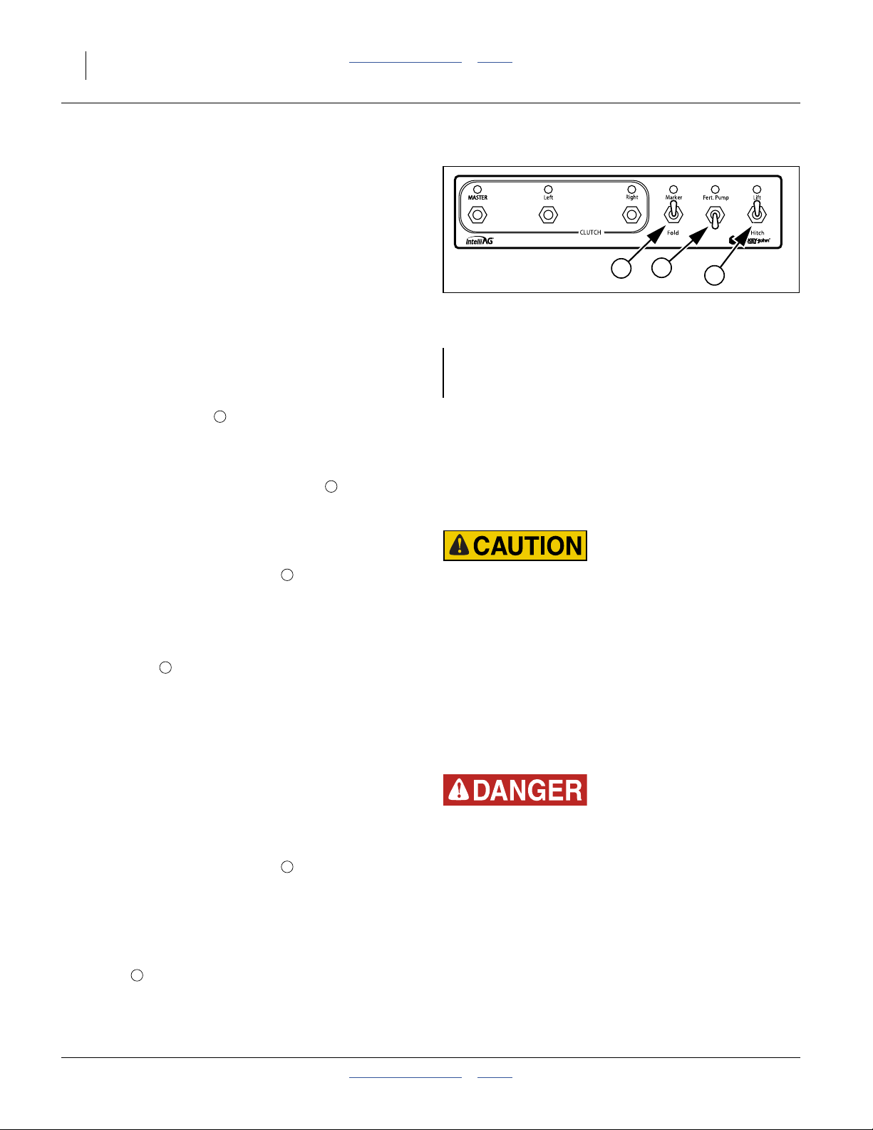
4. Check that hitch local bypass valve is closed.
Refer to Figure 7
5. Set the cab CFM (Clutch Folding Module) Lift/Hitch
switch to Hitch.
6. Retract the Hitch/Lift circuit to set the tongue height
to clear the draw-bar. Back the tractor into alignment
and pin the draw-bar.
Local Float on Hydraulic Tongue
Refer to Figure 6
The hydraulic tongue must be in Float during planter
moves.
If it is necessary to move the planter without first
connecting it to a tractor that has a float-capable circuit
for the hydraulic tongue, open the bypass valve on the
tongue cylinder. This provides local floating capability at
the tongue.
2
3
3
OPEN
3
CLOSED
Hitching with Hydraulic Tongue
2
Figure 5
3-Point Hitch Stands Stored
Figure 6
Figure 7
CFM for Hydraulic Hitching
1
29732
28477
2
28483
401-625M Table of Contents Index 2013-08-13
Page 21
Great Plains Manufacturing, Inc. Table of Contents Index Preparation and Setup 17
Raising/Lowering Tongue
In addition to hitching, tongue raising and lowering is
required during fold and unfold to engage and disengage
the wing locks.
With the standard 3-point hitch, the planter tongue is
raised and lowered by raising and lowering the 3-point.
With the optional hydraulic tongue, the planter tongue is
raised by extending the hitch cylinder, and lowered by
retracting the hitch cylinder.
h
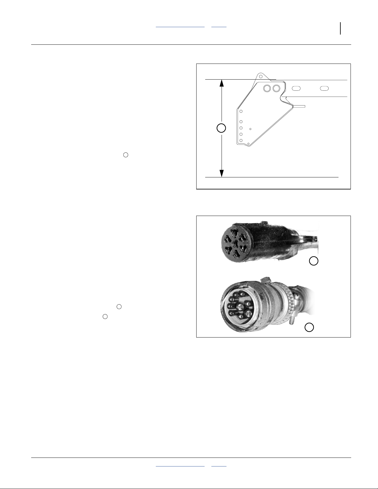
Hitching with Either Hitch
7. Set the initial tongue height, using 3 point or cylinder
of hydraulic tongue. Distance , measured at top of
tongue tube is:
46 inches (117 cm) above ground level for YP12, or
42 inches (107 cm) above ground level for YP16.
Additional planter leveling information is found on
page 147.
8. Connect other hydraulic hoses to tractor remotes.
See “Hydraulic Hose Hookup” on page 14
h
Figure 8
Base Height
25316
Electrical Hookup
Refer to Figure 9
Your planter is equipped with two standard systems
requiring separate electrical connections. You may also
have optional equipment requiring additional
connections.
Make sure tractor is shut down with accessory power off
before making connections.
These connections may be made in any order. The key
requirement is that all connections be made prior to
planter movement.
9. Plug the planter light cable to the tractor.
10. Connect monitor lead to monitor harness. (See
page 146 for console installation.)
11. Connect any optional harnesses.
1
2
Figure 9
Connector Identification
1
2
25236
25237
2013-08-13 Table of Contents Index 401-625M
Page 22
18 YP1125A & YP1625A Table of Contents Index Great Plains Manufacturing, Inc.
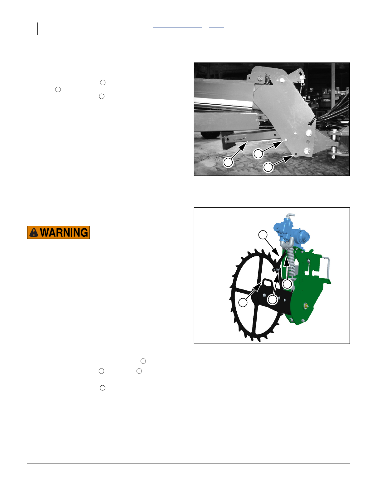
Store Main Parking Stand
Refer to Figure 10
12. Remove the lower pin holding the parking
7
stand . Swing the parking stand back and up until it
is above the rear hole . Place the holding pin in the
rear hole and allow the parking stand to rest on it.
This will be the transport position for the parking
stand.
13. Adjust the top link of a 3-point long enough so the
ball swivel does not bottom out when fully raised.
14. Secure hoses using hose post loops (not shown) so
that hoses have ample slack for lifts and turns, but
cannot get caught in tongue lock or ball swivel.
Failure to do so could cause hose to be crushed
requiring hose replacement.
15. If equipped with hydraulic hitch option, connect
safetychainto a suitable anchor point on the tractor.
5
6
6
7
Storing Parking Stand
5
Figure 10
22813
Lock Up Fertilizer Drive
YP1225A serial number B1059E+
YP1625A serial number B1106F+
Loss of Control and Sharp Object/Crushing Hazards:
Do not lift or lower wheel by spoke or rim; use handle only.
Keep legs and feet out from under wheel. 90 pounds (41 kg)
force is required to lift wheel. If you lose your grip before
pinning, or after unpinning, the arm snaps down rapidly. The
traction teeth and the force of the wheel impact can inflict
serious injury.
The liquid fertilizer option uses a piston pump driven by a
ground contact wheel. When not using the fertilizer drive,
preserve the pump by locking up the ground wheel. On
older models remove the chain.
Note: Do not operate planter pump when not applying
material.
Refer to Figure 11
For YP1225A and YP1625A planters:
16. Remove clevis pin from storage hole .
17. Release the lock arm , lift handle to lift ground
wheel up to position it in-between lock arm.
18. Secure with pin clevis and cotter pin.
5 7
6
4
5
4
7
Locked Up Fertilizer Drive
6
Figure 11
32364
401-625M Table of Contents Index 2013-08-13
Page 23
Great Plains Manufacturing, Inc. Table of Contents Index 19
Operating Instructions
This section covers general operating procedures.
Experience, machine familiarity and the following
information will lead to efficient operation and good
working habits. Always operate farm machinery with
safety in mind.
Pre-Start Checklist
1. Carefully read “Important Safety Information” on
page 1.
2. Lubricate planter as indicated under “Lubrication”
on page 104.
3. Check all tires for proper inflation. See “Tire
Inflation Chart” on page 127.
4. Check all bolts, pins and fasteners. Torque as shown
in “End of “Appendix A - Reference Information”.”
on page 140.
5. Check planter for worn or damaged parts. Repair or
replace parts before going to the field.
6. Check hydraulic hoses, fittings and cylinders for
leaks. Repair or replace before going to the field.
7. Be sure hydraulic hoses are securely held out of the
ball swivel area at hitch. Failure to do so could cause
hoses to pinch requiring hose replacement.
High Pressure Fluid Hazard:
Check all hydraulic lines and fittings before applying pressure.
Escaping fluid under pressure can have sufficient pressure to
penetrate the skin. Fluid escaping from a very small hole can
be almost invisible. Use paper or cardboard, not body parts,
and wear heavy gloves to check for suspected leaks. If an accident occurs, seek immediate medical attention from a physician familiar with this type of injury.
1
4
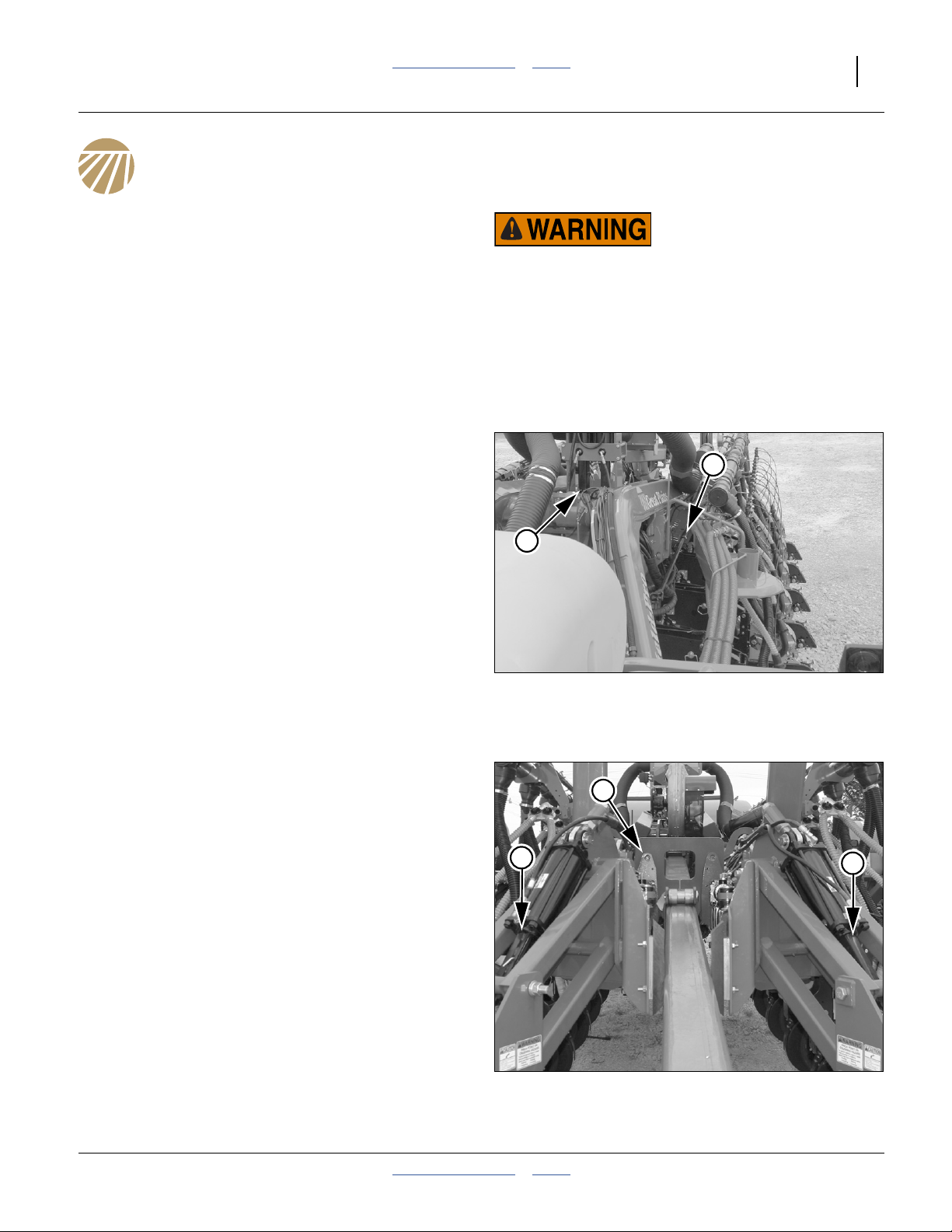
Wing Lock Overview
Refer to Figure 12 and Figure 13
The YP1225A & YP1625A planters include four sets of locks for the frame and wings:
1. Transport hooks behind the wing pivots:
These prevent the planter frame from fully lowering
when folded. The planter frame is raised to allow the
wings to clear the hooks. See page 20 and 26.
2. Wing locks at mid-tongue and inside wing casters:
These prevent the planter from unfolding while in
transport. The tongue (hitch) is raised to allow the
hooks to clear the locks. See page 21 and 26.
3. Transport lock channels at wing caster cylinders:
These lock channels prevent the frame from fully
lowering during transport and maintenance. They
are installed prior to folding, and removed after
unfolding. See page 22 and 26.
4. Lift cylinder lock channels above frame pivots:
These lock channels are only required during
maintenance. However, if installed, they must be
removed after unfolding. See page 22 and 89.
3
Lift Locks and Transport Hook
2
Wing Lock and Transport Locks
Figure 12
Figure 13
29734
3
29735
2013-08-13 Table of Contents Index 401-625M
Page 24
20 YP1125A & YP1625A Table of Contents Index Great Plains Manufacturing, Inc.
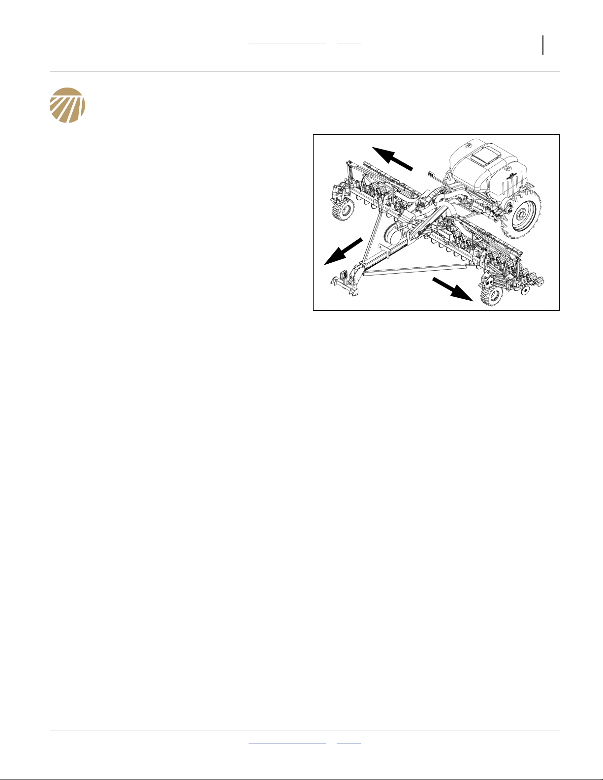
Unfolding The Planter
The distance between the tractor and the seed structure
decreases by about 10 feet (3 m) during unfolding.
Planter, tractor, or both will move during this operation.
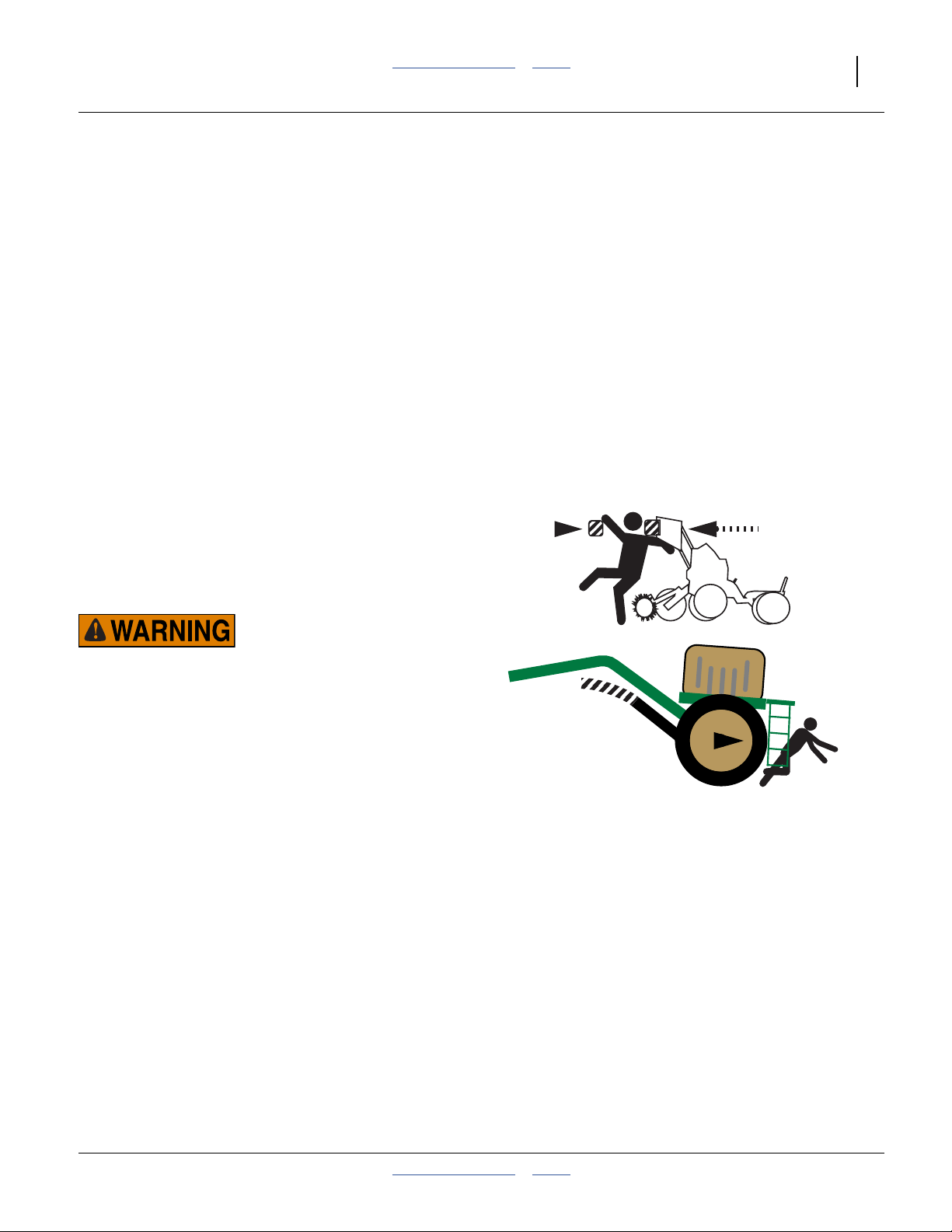
Crushing, Pinch-Point and Overhead Hazards:
To prevent serious injury or death:
▲ Unfold only on hard level ground. Allow ample room.
▲ Allow no one on or near the planter during unfolding.
▲ Stay clear of the wing sweep arcs. The sweep arcs of the
wings have numerous pinch and crush points in the mechanism. Coulters and row openers are sharp.
▲ Allow no one near planter during unfold. The seed structure
usually moves forward during unfolding.
▲ Do not unfold with planter lowered.
▲ Unfold only with markers resting in transport cradles.
▲ Unfold only if hydraulics are bled free of air and fully
charged with hydraulic oil.
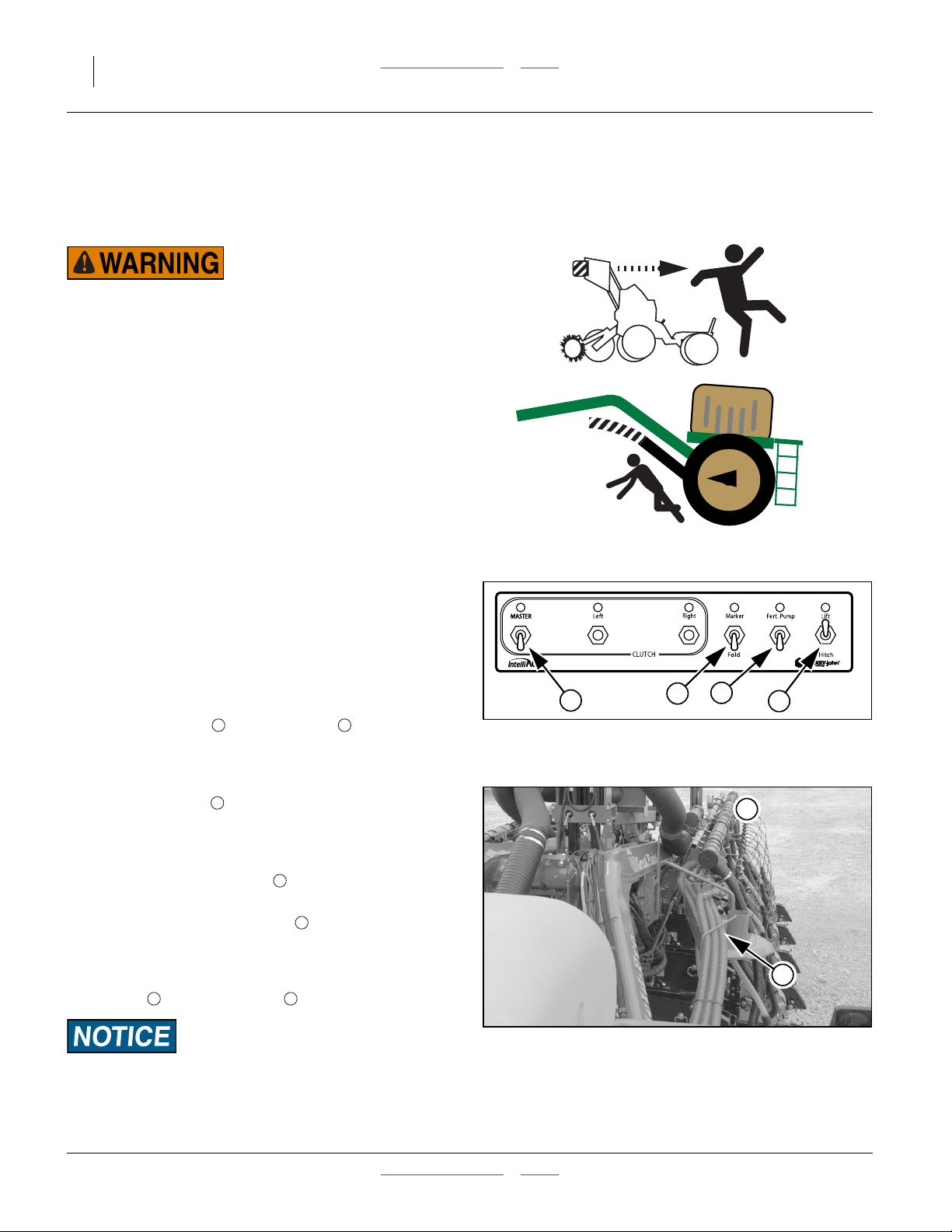
Prepare Hitched Tractor and Planter
1. Move planter to level ground.
2. If tractor movement is not desired, put tractor in Park
and/or set parking brakes, or telescoping movement
of planter may cause tractor to move backward.
3. On the CFM (Clutch Folding Module), set the
following switches to OFF (down):
MASTER switch and Fert.Pump .
1 2
Prepare Transport Hooks
Refer to Figure 15
The transport hooks , behind/above wing pivots,
prevent the frame from fully lowering when the planter is
fully folded. To clear the hooks, the frame is fully raised.
Refer to Figure 14
4. Set CFM Lift/Hitch switch to “Lift” to enable lift
cylinder hydraulics.
5. Set CFM Marker/Fold switch to “Fold” to enable
fold cylinder hydraulics.
6. Activate lift hydraulics. Raise planter until lift
hydraulics are fully raised. This raises the wing
frames above the hooks .
6 5
5
3
4
2
1
4
Figure 14
CFM for Unfold
3
28484
6
5
Figure 15
Planter Damage Risk:
Be sure planter’s lift hydraulics are fully raised before
unfolding or frame and/or hook damage WILL occur.
401-625M Table of Contents Index 2013-08-13
Transport Hook
29734
Page 25
Great Plains Manufacturing, Inc. Table of Contents Index Operating Instructions 21
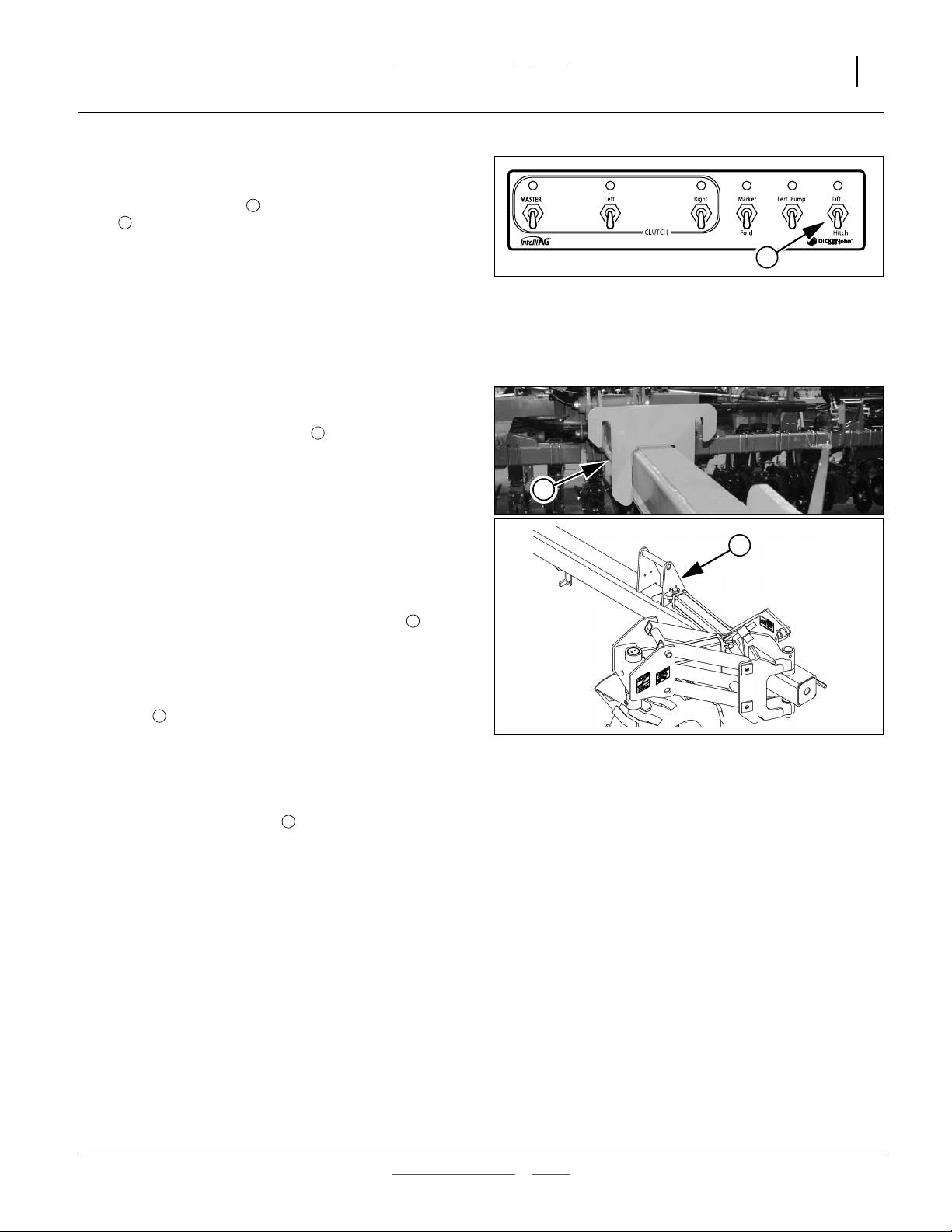
Release Wing Locks
Refer to Figure 17
A pair of inverted hooks on the tongue tube engage
8
locks on each wing when the planter is folded.
Prior to unfolding, this lock system must be released by
raising the tongue.
7. This step is slightly different depending on hitch type.
Release Wing Lock with 3-Point Hitch
a. Raise the 3-point hitch to disengage the wing
lock. Continue at step 8.
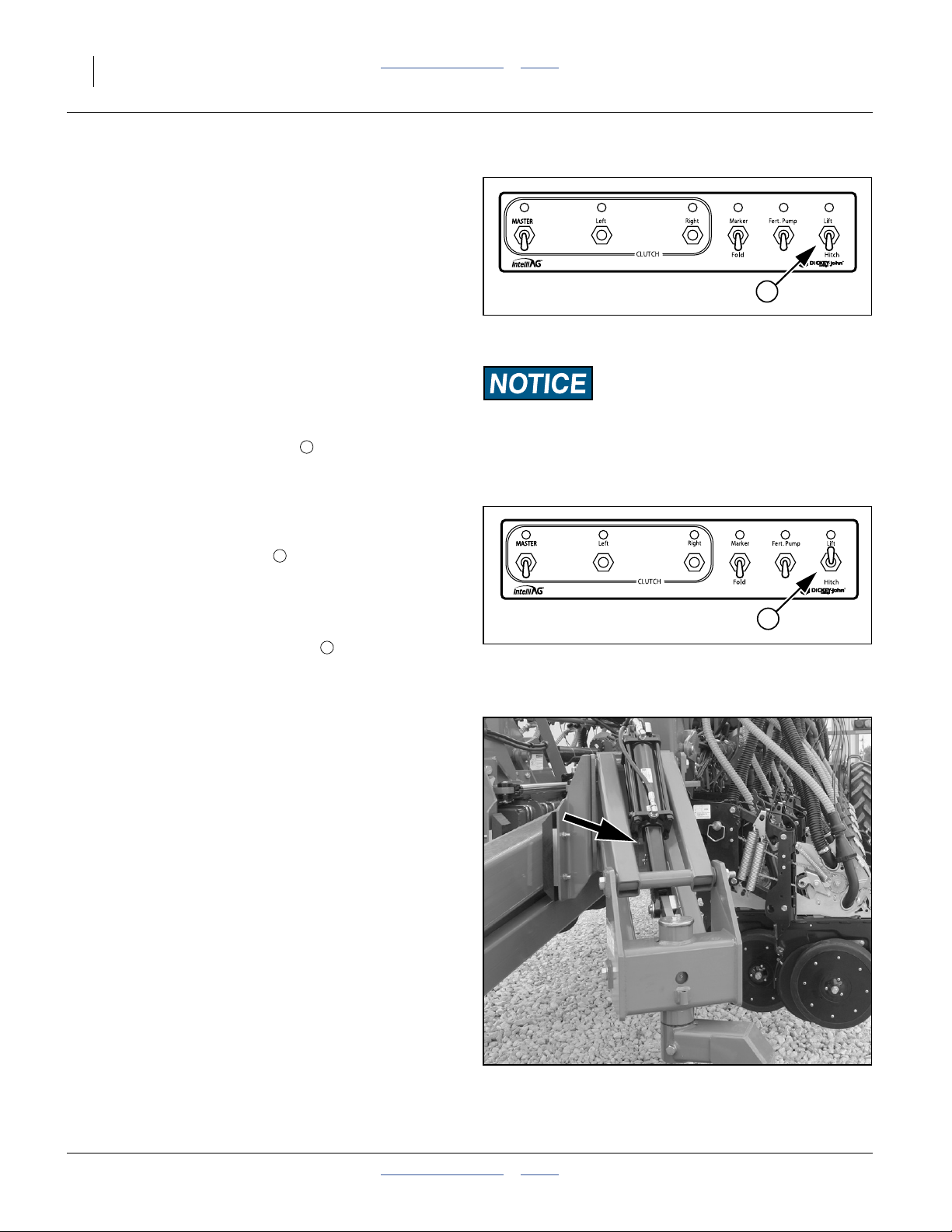
Release Wing Lock with Hydraulic Hitch
Refer to Figure 16
a. Set CFM Lift/Hitch switch to Hitch.
b. Raise hydraulic tongue to disengage wing lock.
7
6
Figure 16
CFM: Wing Unlock
(Hydraulic Hitch Only)
6
28483
Re-Phase Fold Cylinders
8. The fold system uses re-phasing cylinders. It is
necessary to re-phase cylinders so wing gauge
wheels run in their fully rotated positions in front of
planter. To re-phase fold cylinders:
Move and hold lever for Marker/Fold in Fold direction
(typically Extend) for 30 seconds. This causes wings
to push against the tongue transport hooks .
7
Partially Unfold
Refer to Figure 17
9. Reverse fold circuit lever until wings clear transport
hooks by a few feet.
7
Lower Tongue
10. Lower 3-point hitch or hydraulic tongue to planting
position. See page 17 and page 147 for correct hitch
height and depth control settings. If hydraulic tongue,
set CFM Lift/Hitch switch to Lift.
6
7
8
Figure 17
Wing Hook & Wing Lock
22815
27288
2013-08-13 Table of Contents Index 401-625M
Page 26
22 YP1125A & YP1625A Table of Contents Index Great Plains Manufacturing, Inc.
Fully Unfold
Refer to Figure 18
11. Unfold the planter fully to planting position. Unfolding
is complete when the large roller bushing on top of
the tongue is engaged by the tongue safety latch .
Planter Damage Risk:
Failure to lower the tongue before unfolding WILL result in
opener or seed delivery system damage. Press wheel assembly
components can strike air system components near the air box
manifold.
9
9
Planter Damage Risk:
Do not plant if the tongue latch is not fully down over the
roller. Frame and opener damage is likely if the planter is
operated with the latch open.
Remove and Store Transport Locks
The planter needs to still be in full lift to remove these
locks.
Remove/Store Center Lift Locks
Refer to Figure 19
12. Remove lock channels from vertical cylinders
above pivots.
Refer to Figure 19 and Figure 20
13. Store lock channels horizontally on tabs at top
right side of lift cylinder weldment.
1
2
Figure 18
Tongue Latch Engaged
28488
2
2
1
Figure 19
Frame Lift Locks
29738
2
Figure 20
Lift Cylinder Lock Stored
401-625M Table of Contents Index 2013-08-13
29736
Page 27
Great Plains Manufacturing, Inc. Table of Contents Index Operating Instructions 23
Remove/Store Caster Lift Locks
Refer to Figure 21
14. Remove transport lock channels from lift cylinders
located on gauge wheels.
3
3
4
Refer to Figure 21 and Figure 22
15. Transfer lift cylinder transport lock channels to
their storage positions .
4
3
Unfold Closeout
16. As appropriate for the next planned activity, activate
lift hydraulics and lower planter.
17. To disable fold hydraulics, and lock caster armsa in
field position, set CFM Marker/Fold switch to
“Marker”.
Note: Set switch to “Marker” even if Markers are not
installed. This switch position disables all fold
solenoid valves.
5
Figure 21
Caster Lift Cylinder Lock
29737
3
4
Figure 22
Transport Cylinder Lock Storage
27290
5
Figure 23
CFM After Unfold
28485
a. YP1125A s/n A1154K+ and YP1625A s/n A1172B+
2013-08-13 Table of Contents Index 401-625M
Page 28
24 YP1125A & YP1625A Table of Contents Index Great Plains Manufacturing, Inc.
Raising/Lowering Planter
The planter mainframe raises and lowers independently
of the tongue.
• The planter may be fully raised at any time (and must
be raised for folding).
• The planter may be lowered onto its transport lock
channels at any time.
• The planter may be fully lowered, with lock channels
removed, only when unfolded.
Refer to Figure 24
The CFM “CLUTCH” switch positions are not shown
because they normally require no attention during lift or
lower. Lifting the planter automatically disengages the
entire drive system.
The “Fert.Pump” switch has no function on YP1225A
& YP1625A planters as shipped by Great Plains because
the optional fertilizer system for these planters uses a
ground-drive pump that has no electrical control.
Leave or set the CFM Marker/Fold switch in “Marker”
position to prevent unintended folding.
1
2
Figure 24
CFM for Lift/Lower
If your planter has an aftermarket pumping system
compatible with the IntelliAg® system, the “Fert.Pump”
switch may require operator attention during lift/lower.
1
2
3
28485
Raising Planter
The planter may be raised at any time.
1. Set the CFM “Lift/Hitch” switch to Lift to enable the
lift cylinder circuit.
2. Move the Lift/Hitch circuit lever to extend the lift
cylinders.
3. Set the circuit to Neutral to hold the planter at lift.
The switch may be left in the “Lift” position.
4. Install lock channels if raising for transport, parking,
storage, adjustments or maintenance.
3
3
Lowering Planter
If lock channels are installed, the planter may be lowered
at any time. if lock channels are not installed, lower only
when unfolded, such as for field turns.
Install lock channels (page 23) as appropriate for next
activity.
1. Set the CFM “Lift/Hitch” switch to Lift to enable the
lift cylinder circuit.
2. Move the Lift/Hitch circuit lever to retract the lift
cylinders until settled on lock channels or fully
lowered to ground.
3. Set the lift circuit to Neutral for field operation. The
switch may be left in the “Lift” position.
3
3
Lowering Planter Hazard:
Use transport locks. A raised planter slowly lowers when held
up solely by circuit neutral. Anyone beneath the row units
could be trapped and injured. Rely on circuit neutral to hold
the planter raised only for brief periods, such as field turns
and during lock channel installation. Use lock channels at all
other times.
Note: After every few hours of operation (or earlier, if
uneven lift is observed), re-phase the lift circuit.
At a lift operation, hold the circuit in Extend for
30 seconds.
Crushing Hazard:
Keep all persons away from frame sections during lift and
lower. Area under row units is particularly dangerous. Sharp
coulter and opener blades descend with hundreds of pounds of
down-force.
Note: Unless lock channels are installed, lower the
planter only when fully unfolded. Lowering when
folded is prevented by the transport locks.
401-625M Table of Contents Index 2013-08-13
Page 29
Great Plains Manufacturing, Inc. Table of Contents Index Operating Instructions 25
Re-phasing Lift System
Over a period of normal use the cylinders may get out of
phase. This will cause some planter sections to run
higher than others. If this is the case, it will be necessary
to re-phase lift cylinders.
Note: Lift cylinders can only be re-phased when planter is
unfolded.
To re-phase cylinders:
1. Raise the implement completely and hold the
hydraulic remote lever on for several seconds until all
cylinders are fully extended. Do this every 8 to
10 times you raise planter out of ground.
2. When all cylinders are fully extended, momentarily
reverse hydraulic remote lever to retract system
1
⁄2inch to maintain levelness.
Folding the Planter
The planter must be raised for folding. The tongue is
raised and lowered during the sequence.
The distance between the tractor and the seed structure
increases by about 10 feet (3 m) during folding. Planter,
tractor, or both will move during this operation.
Pinch Point and Crushing Hazard:
To prevent serious injury or death:
▲ Fold only with planter raised and lock channels installed.
▲ Fold only if hydraulics are bled free of air and fully charged
with hydraulic oil.
▲ Stay away from frame sections when they are being raised
or lowered.
▲ Keep away and keep others away when folding or unfolding
planter.
▲ Fold markers onto cradles before folding planter.
2013-08-13 Table of Contents Index 401-625M
Page 30
26 YP1125A & YP1625A Table of Contents Index Great Plains Manufacturing, Inc.
Shut off Fan and Hydraulic Drive
1. Set circuit levers for seed box fan and optional
hydraulic meter drive to Neutral.
Set Tractor and Tongue
2. Raise and move planter to a level area.
3. If tractor movement during folding is not desired, put
tractor in Park and/or set parking brake.
4. This step is slightly different depending on hitch type:
Prepare 3-Point Hitch for Fold
a. Fully lower 3-point hitch. Continue at step 5.
Figure 25
CFM: Prepare Hitch for Fold
1
28487
Prepare Hydraulic Hitch for Fold
Refer to Figure 25
a. Set CFM Lift/Hitch switch to “Hitch”.
b. Retract hitch cylinder to fully lower tongue.
1
Raise Planter
Refer to Figure 26
5. Set CFM Lift/Hitch switch to “Lift”.
6. Activate circuit lever to extend lift cylinders until
planter is fully raised.
7. Set circuit to Neutral to hold at lift.
8. On hydraulic hitch, return switch to “Hitch”.
9. Put tractor in Park and/or set parking brake, and shut
off tractor.
2
2
Install Lock Channels
Only wing (gauge wheel) lock cylinders need to be
installed for transport. The center is adequately
supported by the wing hooks and locks when folded.
For servicing, or to hold at lift when unfolded, also install
center section lift locks (see page 89)
Refer to Figure 27
10. Remove lift cylinder transport lock channels from
their storage positions.
11. Place transport lock channels on lift cylinders
located on gauge wheels.
Equipment Damage Risk:
Tongue must be lowered at start of fold to ensure that press
wheel assemblies remain clear of air system.
2
Figure 26
CFM: Raise Planter
28484
Figure 27
Transport Cylinder Lock in Use
401-625M Table of Contents Index 2013-08-13
29737
Page 31

Great Plains Manufacturing, Inc. Table of Contents Index Operating Instructions 27
Activate Fold Solenoid Valves
Refer to Figure 28
12. Set CFM Marker/Fold switch to “Fold”. This opens
the solenoid valves for tongue lock, fold cylinders
and caster arm
a
cylinders.
3
Begin Folding
13. Extend the fold cylinders and fold the planter until the
wing tubes are within a few feet (a meter or so) of the
tongue.
Raise Tongue
14. Raise 3-point hitch or hydraulic hitch until wing
hooks on tongue clear locks on wings.
4 5
Complete Fold
15. Continue or resume folding until the wing locks
contact lock plate (under hooks).
16. Set CFM Marker/Fold switch to “Markers”.
Note: When folded, set the “Marker/Fold” switch to
“Marker”, whether Markers are installed or not. In
this position, the switch disables all solenoid valves
for fold, locking the fold system.
3
Lower Tongue
17. Lower 3-point hitch or hydraulic tongue until wing
hooks rest on wing locks.
Re-phasing Fold System
Over a period of normal use, the cylinders may get out of
phase. This is evident by wing gauge wheels not running
in their fully rotated positions in front of the planter.
Note: Planter must be folded to re-phase fold system.
See “Re-Phase Fold Cylinders” on page 21.
3
Figure 28
CFM: Commence Fold
2
28484
4
5
Figure 29
Wing Hook & Wing Lock
22815
27288
a. Feature on YP1225A s/n A1154K+ and YP1625A s/n A1172B+ planters.
2013-08-13 Table of Contents Index 401-625M
Page 32

28 YP1125A & YP1625A Table of Contents Index Great Plains Manufacturing, Inc.
Transporting
The tractor must weigh at least 2/3 (67%) of the planter
plus any materials loaded. See table below for typical
planter weights. Have your planter weighed if the tractor
capability is not clearly above requirements.
Before transporting, follow and check these items:
• Set the tractor 3-point hitch control for depth control
operation. If the 3-point hitch control is set for load
control, the auto load control response may
automatically adjust too high in some circumstances,
causing the wing locks to disengage on the road.
• Empty seed box. Empty seed box before transporting
if at all possible.
• The planter can be transported with a full box of grain,
but the added weight increases stopping distance and
decreases maneuverability.
• Transport planter only while in folded position. Refer to
“Folding the Planter” on page 25 and make sure
cylinder lock channels are in place.
• Warning lights. Always use warning lights when
transporting the planter.
• Road rules. Comply with all national, regional, and
local safety laws when traveling on public roads.
• Clearance. Remember that the planter is wider than
the tractor. Allow safe clearance.
• Transporting with Markers. Always transport markers
in the folded position. Make sure second marker
section rests securely on transport carrier.
Loss of Control Hazard:
Do not exceed 20 mph (32 km/h).
Use a tractor rated for the load.
Towing the planter at high speeds or with a vehicle that is not
heavy enough could lead to loss of vehicle control, resulting in
a serious road accident, injury and death.
Weights of Representative Planter
Configurations
Base Planter Weight
Typical Empty Standard* Planter
Typical Full Standard* Planter
Typical Empty Maximum* Planter
Typical Full Maximum* Planter
-1230 -16TR36 -1820 -2315 -24TR -1670
15540 lb 16410 lb 16850 lb 17940 lb 18160 lb 7570 kg
16400 lb 17280 lb 17710 lb 18800 lb 19020 lb 7960 kg
21650 lb 22530 lb 22960 lb 24050 lb 24270 lb 10340 kg
18460 lb 19560 lb 20120 lb 21500 lb 21780 lb 9000 kg
28500 lb 29610 lb 30170 lb 31550 lb 31830 lb 13560 kg
Note: the weight of a specific planter
can vary significantly.
Base Planter Weight
Typical Empty Standard* Planter
Typical Full Standard* Planter
Typical Empty Maximum* Planter
Typical Full Maximum* Planter
* Typical Standard configuration is: markers, 82 bushel hopper, no fertilizer, no coulters
Typical Maximum configuration is: markers, 82 bushel hopper, starter fertilizer system, UM coulters
401-625M Table of Contents Index 2013-08-13
-1236 -1630 -2420 -24TR36 -3115 -32TR
15800 lb 16670 lb 18420 lb 18420 lb 19940 lb 20160 lb
16660 lb 17530 lb 19280 lb 19280 lb 20810 lb 21030 lb
21910 lb 22780 lb 24530 lb 24530 lb 26060 lb 26270 lb
18720 lb 19830 lb 22050 lb 22050 lb 23990 lb 24270 lb
28770 lb 29880 lb 32100 lb 32100 lb 34040 lb 34320 lb
YP1225A- YP1625A-
YP1625A-
Page 33
Great Plains Manufacturing, Inc. Table of Contents Index Operating Instructions 29
Loading Materials
The YP1225A & YP1625A planters accept the Great
Plains 82 bu. hopper,150 bu.
a
hopper, or bulk seed
boxes that meet the PioneerbPROBOX® specification.
Material Loading Overview
• With hoppers, seed is loaded from above, with the
hopper already mounted on the planter.
• With a bulk seed box, seed is pre-loaded by the seed
supplier, and the box is mounted on the planter
already loaded.
• If the optional fertilizer system is installed, liquid
fertilizer is normally pumped in from below via the
quick-fill system, but may also be gravity-loaded from
above with the tank caps removed.
Tipping and Overload Hazard:
Place or remove a hopper only when empty. A full hopper can
weigh between 5,000 and 10,000 lbs (2700-4500 kg), which is
above the lifting and balance capability of most tractors and
farm forklifts.
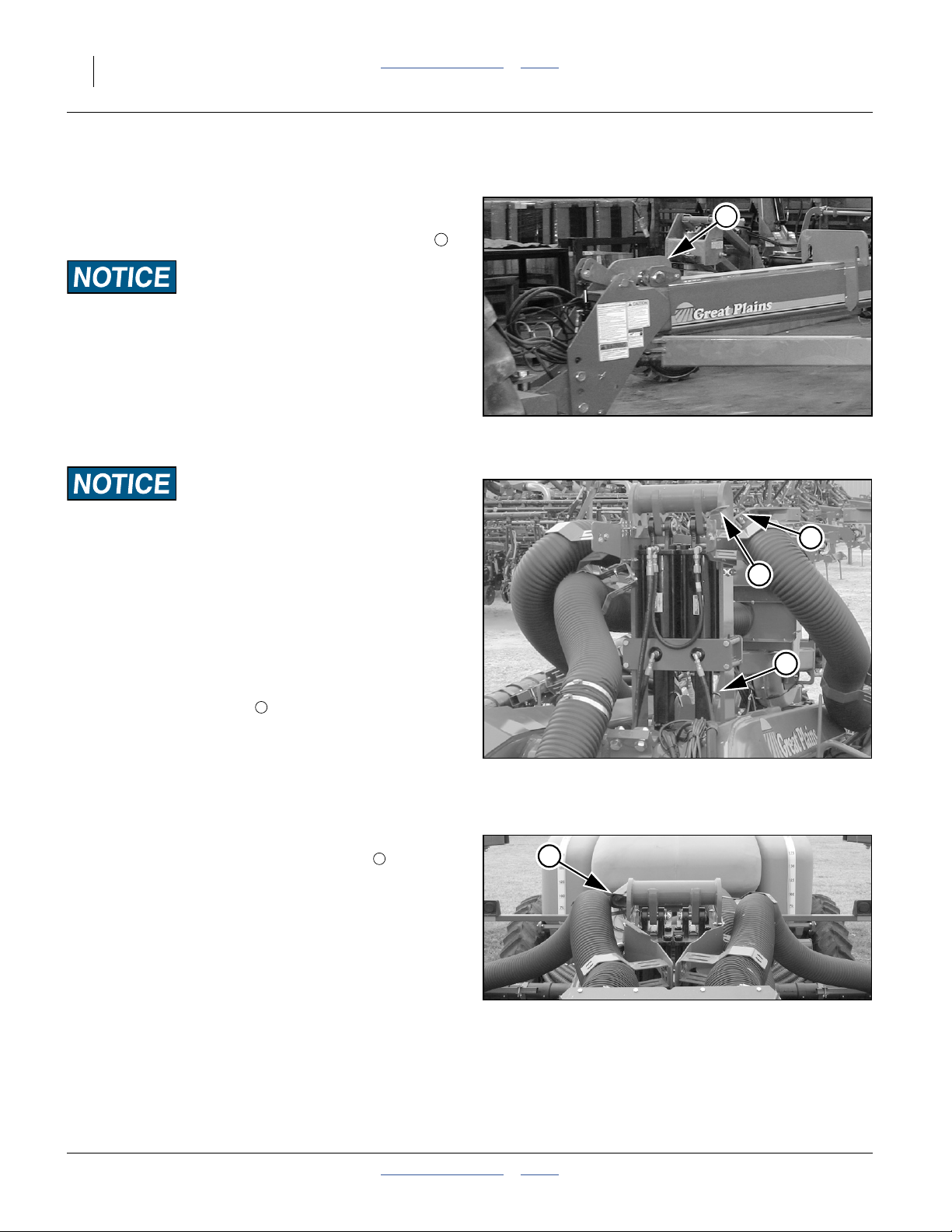
Mounting a Hopper or Bulk Seed Box
These steps cover mounting a hopper or seed box on a
planter that has no seed container. If a seed container
needs to be removed first, see page 34.
1. Move the planter to an area of level ground and
sufficient room to maneuver a tractor or fork-loader.
2. If changing between hopper and bulk seed box, use
the Accessory Sensor Setup menu on the seed
monitor console to disable the hopper sensor and
avoid nuisance alarms. See DICKEY-john® Quick
Start Guide.
3. Place tractor in park, shut off engine, and remove the
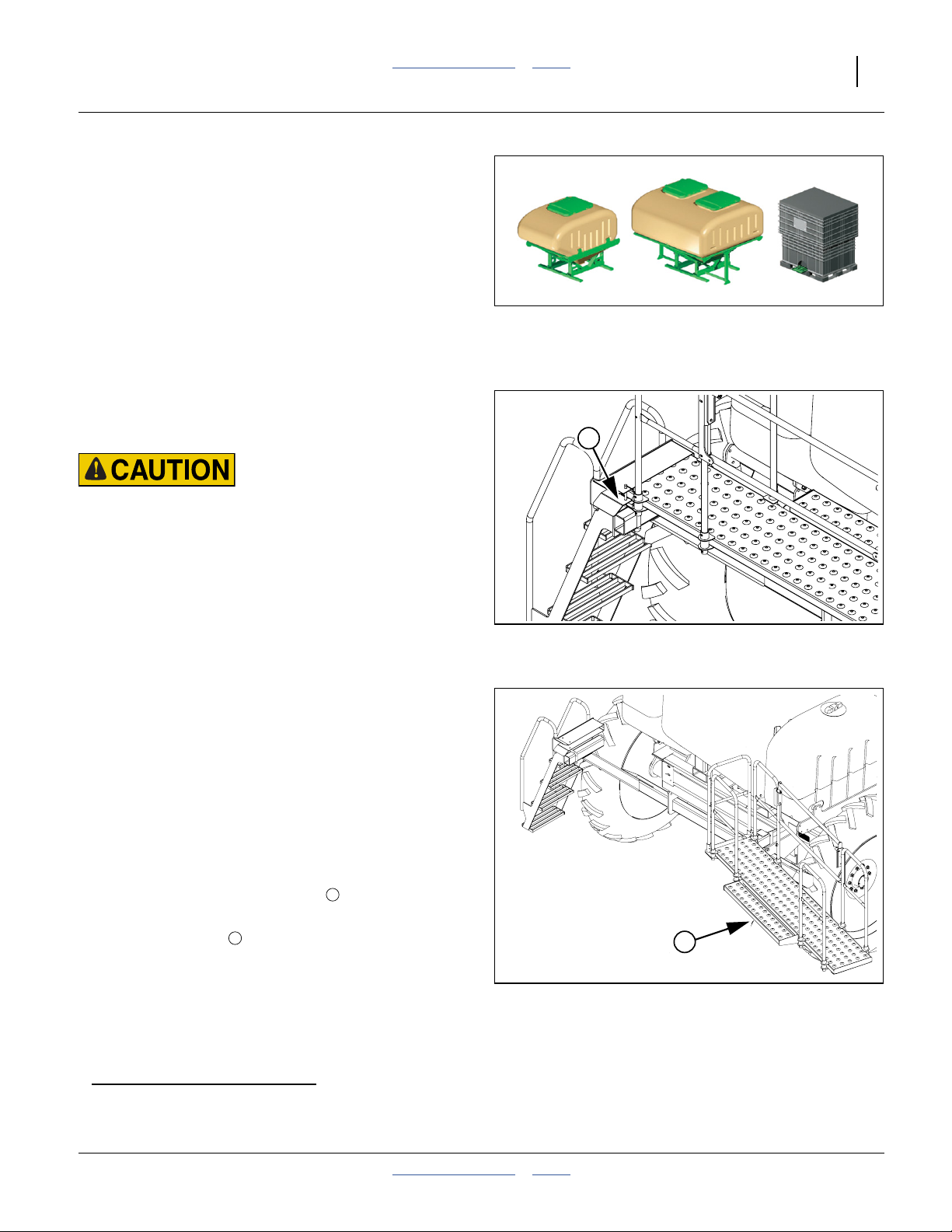
key. If using the same tractor for container mounting,
block the planter transport tires.
Refer to Figure 31
4. Remove the walkboard lock pin .
Refer to Figure 32
5. Swing walkboard all the way to the right.
2
1
Figure 30
82 bu. and 150 bu. Hoppers,
and a Bulk Seed Box
1
Figure 31
Walkboard Lock Pin
2
29486
24010
Figure 32
24005
Walkboard Open
a. The 150 bu. hopper is incompatible with on-board fertilizer tanks.
b. PROBOX
2013-08-13 Table of Contents Index 401-625M
®
is a registered trademark of Pioneer Hi-Bred International, Inc.
Page 34

30 YP1125A & YP1625A Table of Contents Index Great Plains Manufacturing, Inc.
Refer to Figure 33
6. Secure walkboard with keeper.
Note: If planter is lowered, walkboard will stay open by
itself once fully opened. There is a keeper near the
walkboard pivot that can hold the walkboard open
in all conditions.
Refer to Figure 34
7. Remove pins at the corners of the airbox frame.
1
Irritation and Chronic Exposure Hazard:
Wear gloves. DO NOT use hands or any part of your body to
mix seed lubricant. Wear a respirator when transferring and
mixing. Avoid breathing lubricant dust. Not an acute hazard.
May cause mechanical eye or skin irritation in high concentrations. As with all mineral spills, minimize dusting during
clean-up. Prolonged inhalation may cause lung injury. Product can become slippery when wet.
8. When using a bulk seed box,
new meters for the first time, or
at the start of each season,
measure out approximately 4 gallons (15 liters) of
seed into a pail. Add1⁄2cup (120 ml) of Ezee Glide
Plus seed lubricant to the pail. Mix and pour into air
box before mounting hopper.
Flow Inconsistency and Stoppage Risk:
Ezee Glide Plus is mandatory for all seed, especially treated
or inoculated seed. Failure to use this seed lubricant as
recommended can cause inconsistent seed flow to meters, and
clogging at meters. See “Seed Lubricant” on page 111.
Note: On a new planter, the interior surfaces of the seed
hoses are somewhat tacky until they are coated
with seed lubricant. Before planting for the first
time, and at the start of each season, add1⁄3cup
(80 ml) Ezee Glide Plus seed lubricant to bottom of
airbox.
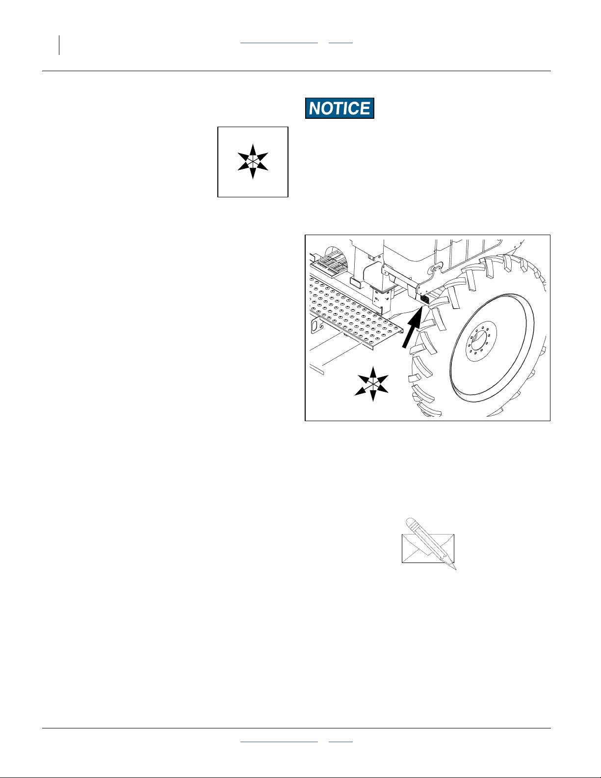
Note: The monitor system includes a level sensor located
below hopper to warn when box is empty. This
typically provides three to four acres (1.2 to 1.6 ha)
of run time before rows start going empty.
9. At the airbox seed inlet, inspect the seals for wear
and damage.
10. If mounting a seed box, add Ezee Glide Plus to the
seed box at this time. It may be easier to add it while
the box is still at ground level.
Figure 33
Walkboard Keeper
1
Figure 34
Airbox Frame Corner Pin
29485
22749
401-625M Table of Contents Index 2013-08-13
Page 35

Great Plains Manufacturing, Inc. Table of Contents Index Operating Instructions 31
Tipping and Overload Hazard:
Make sure your tractor or fork lift is rated for and configured
to lift the hopper or bulk seed box. A full bulk seed box can
weight over 2500 lbs. Do not let anyone stand under or in front
of the elevated seed box.
Refer to Figure 35
11. Approach the hopper or seed box from the back (the
side with the slide gate). Align the forks with the slots
in the rear of the seed box or hopper and slowly drive
forward until forks are completely under the seed box
or hopper.
Note: Bulk hopper frame has two sets of lifting points.
One set is for normal loading and is tubes. The
other set is to allow picking it up from the side for
placing in storage near a wall.
Note: It may be necessary to adjust the seal on top of air
box to getfull contact with the bottom of seed box or
hoppers. This is a one-time adjustment.
Figure 35
Approaching Hopper
25255
Refer to Figure 36
12. Slowly lift the full seed box or empty hopper, and
place it in the planter airbox frame.
13. Install the box retaining pins in frame corners.
Refer to Figure 37
14. Unless you are at the field to plant, close the slide
2
gate at the base of the hopper.
15. Return the walkboard to the closed position and
install the latching pin.
16. If installing an empty hopper for planting, load seed
(and lubricant). Otherwise, skip to step 24 on
page 33.
Figure 36
Fork-Lifting Seed Box
2
24037
Figure 37
29495
Hopper Slide Gate Closed
2013-08-13 Table of Contents Index 401-625M
Page 36

32 YP1125A & YP1625A Table of Contents Index Great Plains Manufacturing, Inc.
Loading Hopper with Seed
Refer to Figure 38
17. At the top of the hopper, release the lid latch(es) .
and open the lid(s):
18. Check that the strainer basket is clean and in
place.
4
3
4
3
Do not operate without a strainer:
It is an important safety feature that prevents accidental entry
into the hopper. It also prevents larger foreign matter from
clogging the air system.
19. Inspect the hopper itself to ensure that it contains
only expected material.
Refer to Figure 39
If using an auger to load seed, access to the top of the
hopper is eased by swinging down the top section of the
center walkboard railing.
20. At each end of the swing-down section, pull the
cross pins inward until the pins clear the holes .
Swing the railing section in or out (it is easier to close
if swung in).
5 6
Figure 38
Hopper Latch and Strainer
29487
6
Using Auxiliary Hydraulic Circuit
The optional auxiliary hydraulic kit includes a manual
valve that diverts the marker hydraulic circuit to a pair of
quick-connect ports at the back of the seed cart.
Refer to Figure 40
A. Extend or fold any marker that is raised. Return the
cab control for that circuit to “off”.
B. Close any shut-off valve on your auger, and connect
the auger to the auxiliary quick-connect ports at the
back of the seed cart.
C. At the auxiliary selector valve (near marker
sequence valve on left wing), move the handle from
“Marker” to “Auxiliary”.
D. With no seed present, open the auger shutoff valve,
and operate the cab control to determine which
setting (“extend” or “retract”) turns the auger in the
correct direction for seed lift.
Figure 39
Walkboard Railing
Figure 40
Auxiliary Hydraulic Ports (Option)
5
29488
25323
401-625M Table of Contents Index 2013-08-13
Page 37

Great Plains Manufacturing, Inc. Table of Contents Index Operating Instructions 33
E. Load seed. Shutoff cab circuit, then auger. Return
Aux valve control handle to “Marker” position.
F. Disconnect auger hydraulic hoses at Aux ports.
Refer to Figure 42 and Figure 43
21. Load seed. Cross-check the expected amount
against the indicator marks molded into the side of
the hopper. The figures at right show the
approximate capacity by fill depth.
22. Connect optional hopper level sensor to monitor
harness.
For planters equipped with optional 82 bu. or 150 bu.
hoppers, an extra level sensor is included. Use
Figure 42 or Figure 43, showing capacity, to place it
at the level that suits your operation. The hopper
sensor is in addition to the air box manifold level
sensor.
23. Close and latch lid(s).
Seed Loading Close-Out
24. If at the planting field, open the slide gate.
Figure 41
Marker/Aux Valve Set to Aux.
Approximate capacity of 82 bu./2890 liter
hopper, at 10in/25.4cm increments
Figure 42
82 bu. Bulk Hopper
Approximate capacity of 150 bu./5290 liter
hopper, at 10in/25.4cm increments
28492
bu liters
82 2890
69 2400
47 1660
26 920
10 350
1.75 60
22958
bu liters
150 5290
132 4650
94 3310
55 1940
22 780
6 210
0.7 20
Figure 43
22958
150 bu. Bulk Hopper
2013-08-13 Table of Contents Index 401-625M
Page 38

34 YP1125A & YP1625A Table of Contents Index Great Plains Manufacturing, Inc.
Dismounting a Hopper or Seed Box
1. Move the planter to an area of level ground and
sufficient room to maneuver a tractor or fork-loader.
2. Place tractor in park, shut off engine, and remove the
key. If using the same tractor for container
dismounting, block the planter transport tires.
3. Remove the walkboard lock pin (page 29).
4. Swing the walkboard completely open and secure
with keeper (page 30).
5. For hoppers with optional level sensors, disconnect
the sensor lead at the harness.
Refer to Figure 44
6. Remove pins at the corners of the airbox frame.
7. Close the slide gate at the base of the hopper or
seed box.
8. Approach the hopper or seed box from the back.
9. Slowly lift the full seed box or empty hopper, and
back it away from the planter airbox frame.
10. Return the walkboard to the closed position and
install the latching pin.
11. If changing between hopper and bulk seed box, use
the Accessory Sensor Setup menu on the seed
monitor console to disable the hopper sensor and
avoid nuisance alarms. See DICKEY-john® Quick
Start Guide.
12. If not installing another seed container, cover the
airbox inlet with plastic sheeting and secure with
tape or bungees.
Figure 44
Seed Box Pins
Tipping and Overload Hazard:
Verify that the hopper or box is empty, or calculate the weight.
Use a tractor or fork lift rated and configured for the weight.
A full seed box can weight over 2500 lbs. Do not attempt to
dismount a full hopper. Do not let anyone stand under or in
front of the elevated seed container.
24036
401-625M Table of Contents Index 2013-08-13
Page 39

Great Plains Manufacturing, Inc. Table of Contents Index Operating Instructions 35
Fertilizer Tanks (Option)
Agricultural Chemical Hazards:
Observe safety precautions specified by material suppliers.
Some chemicals can cause serious burns, lung damage and
death. Avoid contact with skin or eyes. Avoid prolonged
breathing of chemical fumes. Wear respirator and other
protective equipment as required by chemical manufacturer.
Seek medical assistance immediately if accident occurs. Know
what to do in case of an accident.
Filling Tanks
Refer to Figure 45
1. Connect nurse-tank hose to quick-fill coupler located
behind the right-hand tank. Lock hose in place with
cam-lock levers.
2. Close valve going to the in-line filter located just
before the pump.
3. Open valves at each tank and at quick-fill coupler.
4. Fill tanks, then close valve at quick-fill coupler, and
disconnect the nurse tank hose.
Note: Always close valve at filter when filling or storing
any liquid in tanks. Failure to do so may allow
material to run out of manifold (boom) outlets
causing contamination from spillage.
Note: Always fill fertilizer tanks to equal levels. If one tank
fills more quickly, shut that tank valve off to raise the
level in the other tank.
Ground Drive Pump
The liquid fertilizer option uses a ground drive positive
displacement pump. For pump operation and pump
maintenance, refer to the pump manual, supplied in the
liquid fertilizer option package. For fertilizer settings, see
the Seed Rate manual.
Stratification and Plugging Risk:
Apply fertilizer soon after material loading. Clean out unused
materials promptly. Fertilizer allowed to remain in the tanks
for an extended period can settle, resulting in excessive and
insufficient concentrations during application. System
plugging can also occur.
2013-08-13 Table of Contents Index 401-625M
Figure 45
Quick-Fill Coupler
22844
Page 40
36 YP1125A & YP1625A Table of Contents Index Great Plains Manufacturing, Inc.
Field Setup Checklist
Use the following checklist as a guide to ensure the
planter is properly setup before using.
ELECTRICAL Page
All connections made 17
Check all lights
Power up monitor. Watch for diagnostics. PDC
Verify Material, Rate and “SPLIT AIR”
Channel setup. Verify Channel setup for
hydraulic drive (Option).
HYDRAULIC Page
Tractor reservoir full
Marker/Aux valve to Marker (Option) 44
All hydraulic circuits connected 15
Fan direction and rpm 42
Hydraulic drive connectiona (Option)
Raise tongue. Lift planter 17
Begin unfold 20
Re-phase fold system 21
Lower tongue 21
Unfold wings. Check for tongue lock. 22
Re-phase lift cylinders 25
Check marker operation 44
Inspect for hydraulic leaks 3
a. Perform a “FILL DISK” operation via the seed monitor.
MECHANICAL Page
Tongue height preset on 3-point 17
Set tractor 3-point hitch to “depth control”
operation (and not load control)
Side to side levelness at gauge wheels 147
Toe-in of wing frames at pull-bars 148
Tongue hook latch operation 22
Marker extension and disk angle set 150
QSG
PDC
39
45
To complete checklists, you may need to refer to the:
SRM: Seed Rate Manual (SRM),
PDC: DICKEY-john® Planter/Drill Control manuals, or
QSG: DICKEY-john® Quick Start Guide
AIR SYSTEM Page
Manifold to PROBOX® or poly hopper seal. 30
Y-splitters turned off for unused rows. 71
Blank disks installed at unused rows. 72
Air leaks (small leaks from PROBOX® are
normal).
Hose routings, no sags and no pinched
hoses. (Check folded and field positions.)
Hoses fully connected to meters and
locked.
Start fan. Turn on seed monitor active air
control. Watch for split air vane movement
or air pressure changes.
Activate the “FILL METER” function of the
monitor. Watch for air vane movement, or
watch meter pressurization go to zero.
On a new planter, pre-lubricate the air
system with Ezee Glide Plus.
Set the meter pressurization target to the
recommended value for the crop.
84
42
PDC
PDC
30
PDC
ROW CLEANERS Page
Check for correct installation of row
cleaners on all rows if equipped.
Check that row cleaners do not catch on
hydraulic hoses.
Carefully watch when folding and unfolding
planter the first time to ensure clearance of
row cleaners.
FERTILIZER Page
Set rate drive sprockets for correct rate.
(Note fertilizer rate is population
dependent.)
Check for correct orifice plates. SRM
Check unused rows are correctly closed off. SRM
Fill system 1/2 full with water and check for
leaks (run pump if possible).
Disconnect drive chain if fertilizer is not
used.
Check all row unit lines are connected and
discharge nozzles or tubes are clear.
SRM
SRM
SRM
SRM
401-625M Table of Contents Index 2013-08-13
Page 41

Great Plains Manufacturing, Inc. Table of Contents Index Operating Instructions 37
METER DRIVE Page
Check all chains are lubricated, proper
tension and move freely without kinks or
tight spots (very important for even
metering)
Ground Drive only: Set range &
transmission sprockets for desired rate.
Check contact wheel gap. 50
Check contact wheel tire pressure. 127
Check action of contact wheel when raising
and lowering, that it makes contact at
ground height.
Lubricate slider joints on drive shafts if not
already done.
Check operation of electric clutches for
point rows.
137
SRM
50
107
38
ROW UNITS
Preset depth handles to 7 holes showing
above “T”
Preset down force springs to 1st notch
(lightest) setting for most conditions, 2nd
notch otherwise.
Set all unit mounted coulters to1⁄4in (6mm)
above opener blade depth.
Check coulter alignment to row.
Check closing wheel alignment. 76
Set closing wheels to first notch (light). 76
Check scraper gaps (option). 67
Lock up splitter rows if needed. 73
Check action and contact of side depth
wheels.
65
61
64
66
SEED METERS Page
Ezee Glide Plus in seed. 30
Correct seed disks installed for crop, seed
size and cell count (and blank disks in
unused rows)
Inlet shutter set to chart value 69
Check timing of meters in Twin Row corn. SRM
70
Monitor Operation
For monitor operation in the field, refer to the
DICKEY-john® Planter/Drill Control manuals supplied
with this unit, and the Seed Rate manual.
The DICKEY-john® Planter/Drill Control manuals are
supplied as two volumes, identified as User Level 1 and
User Level 2/3, which correspond to access levels in the
monitor menus.
User Level 1 includes items controlled by the tractor
operator during planting.
User Level 2 is password-protected, and includes planter
configuration settings, and some other setup items.
User Level 3 is for dealer and Great Plains use only.
2013-08-13 Table of Contents Index 401-625M
Page 42

38 YP1125A & YP1625A Table of Contents Index Great Plains Manufacturing, Inc.
Electric Clutch Operation
Refer to Figure 46, which depicts the left planter side on and
the right side shut off.
Electric clutches allow for turning planting off while the
planter is lowered. When the planter is raised, clutches
are always
A clutch for each drive shaft allows for independent
control of each side of the planter. The clutches are
controlled via the CFM “CLUTCH” switches.
For regular field operation, turn “MASTER” , “Left”
and “Right” clutch switches to the “ON” position. This
activates the magnet on each clutch and allow clutch
shafts to rotate.
To shut off planting on one or both sides to
accommodate point row while planter is lowered, switch
either to “OFF” position. Turning the MASTER switch off
disengages both sides. If the planter has hydraulic meter
drive, MASTER off also shuts down the drive motor.
Electric Clutch Lockup
Refer to Figure 47
In case of electric clutch failure, electric clutches can be
locked in the engaged mode using metric bolts stored in
the brace plate above each clutch.
1. Remove rubber plugs from oil shield to gain
2. Align cutouts at bolt holes .
3. Insert M8-1.25×14 mm long metric bolts .
Note: Use only 14 mm length bolts as provided or
4. If you observe half the hole obstructed by a metal
5. Replace oil shield plugs.
If the entire hole is obstructed by a metal disc , you are
not at a cutout.
When at a cutout, the bolt will screw in with minimal
resistance until the bolt head reaches the clutch face.
a
off, due to the lift switch.
1 2
3
1 2
access to bolts .
machine damage can occur. Longer bolts will
damage the clutch. Shorter bolts may not effect a
lock-up.
5
disc , you are not at a cutout.
3
4
3
5
1
2
Figure 46
CFM: Point Row
4
Figure 47
Electric Clutch Lockup
5
3
28490
2
3
1
29329
4
Clutch Slippage Risk:
Keep oil shield and oil shield plugs in place. Do not allow
lubricant to enter the clutch when lubricating the planter.
If clutches slip, operate with clutch lock-up until overhaul or
replacement of clutches.
a. On planters with hydraulic drive, the seed monitor overrides the lift switch during “FILL DISK” and “5 REV TEST” operations.
401-625M Table of Contents Index 2013-08-13
Clutch Plate Nearly at Cutout
Figure 48
26168
Page 43
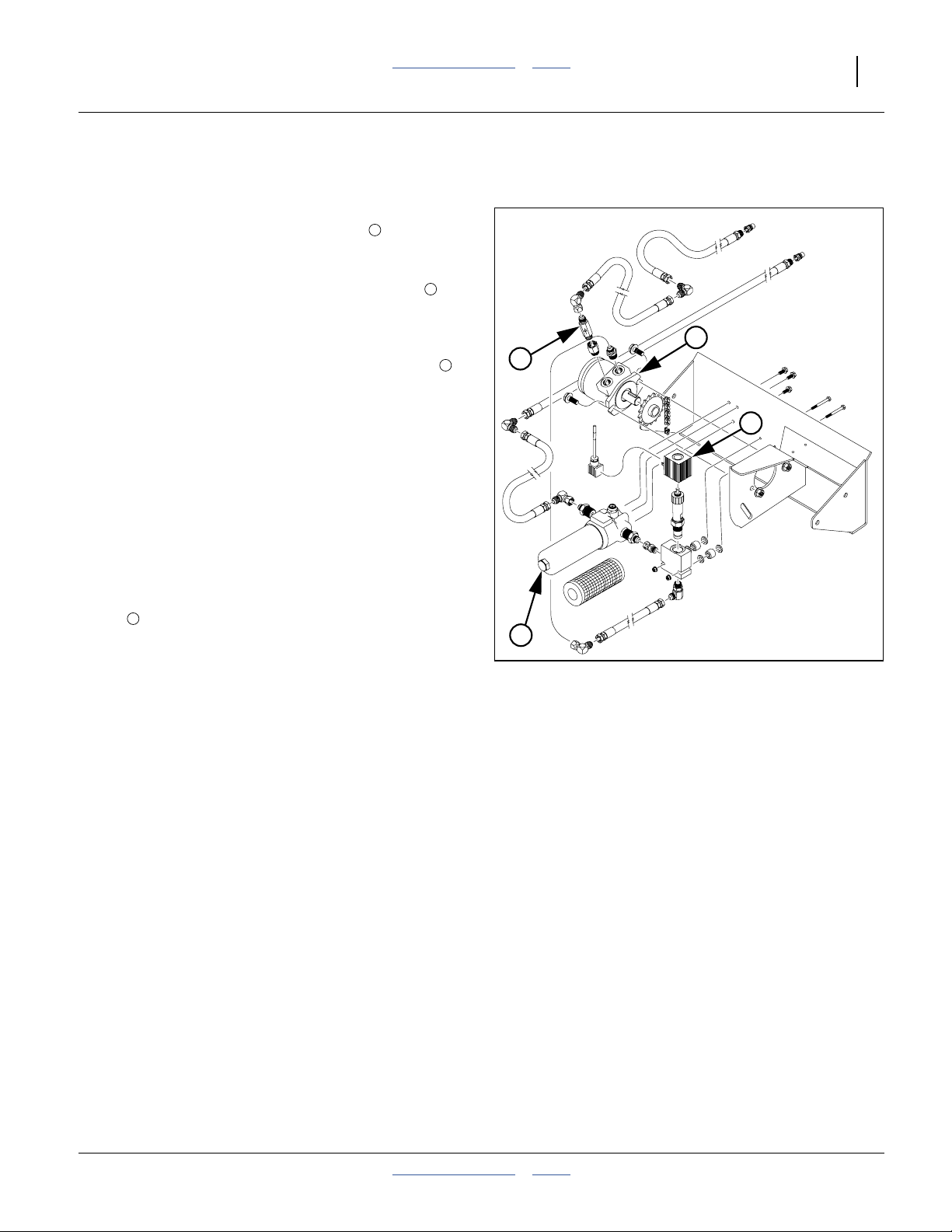
Great Plains Manufacturing, Inc. Table of Contents Index Operating Instructions 39
Hydraulic Drive Operation (Option)
Refer to Figure 49
The hydraulic drive option replaces the standard contact
wheel ground drive with a hydraulic motor , as the
power source for meter rotation.
The drive requires a separate closed center hydraulic
circuit capable of 4.5 gpm (17 lpm). A check valve at
the motor prevents reverse operation, should the
connections be reversed at the tractor, or the circuit lever
reversed.
When the hydraulic circuit is active, a solenoid valve
controls flow to the motor, as the “Planter Channel” of the
seed monitor. Refer to the DICKEY-john® Planter Drill
Control manual, User Level 2/3.
When the planter is raised in normal field operations, the
lift switch causes the seed monitor to shut off hydraulic
flow to the motor. You can override this shutoff, and
operate the drive while raised, using special seed
monitor modes:
• In User Level 1, the “FILL DISK” operation runs the
motor for one meter disk revolution.
• In User Level 2, the “5 REV TEST” operation runs the
motor for five meter disk revolutions.
A filter in the system requires periodic maintenance.
4
See “Hydraulic Drive Maintenance” on page 99.
If there is no meter rotation when expected, the circuit
lever or connections may be reversed. Also check for
solenoid valve problems, such as a disconnected lead,
and any seed monitor diagnostic messages.
1
2
To Tractor
To Tractor
1
3
2
3
4
Figure 49
Hydraulic Drive
28475
2013-08-13 Table of Contents Index 401-625M
Page 44

40 YP1125A & YP1625A Table of Contents Index Great Plains Manufacturing, Inc.
Air System Operation
9
8
16
7
14
1
2
5
4
3
5
6
11
10
12
13
15
Figure 50
Yield-Pro® Air System for Air-Pro® Seed Metering
Meter Pressurization System Elements ( shows air direction)
1 7 13
Hydraulic Fan Pressure Sensor Lines Air-Pro® Seed Meter
2 8 14
Split-Air Manifold Pressure Sensor Chamber Row Pressurizing Tubes
3 9 15
Servo-Controlled Vane Feedback Signal Line Row Unit Seed Tube
4 10 16
WSMT Servo Programming Air Box & Seed Manifold IntelliAg® Console
5 11
Priority Meter Pressurization Air Seed Delivery Hose
6 12
Excess Air to Air Box Air Release Screen
29595
401-625M Table of Contents Index 2013-08-13
Page 45

Great Plains Manufacturing, Inc. Table of Contents Index Operating Instructions 41
Air System Overview
10
1
2 3
5
6
7
9
11
12 13
14
15
16
4
There are console menus for adjustment of metering air,
and manual fall-back modes.
In the case of insufficient fan air, or significant seed
delivery air leaks, seed flow may be irregular or stop.
Meter Pressurization is displayed by a mechanical
8
gauge, and by sensors connected to the seed monitor
system. As these sensors measure pressure at similar
locations, they generally agree.
If seed delivery air flow is insufficient, the indication will
be low seed rate alarms. If fan speed and direction are
as recommended, check for air leaks in the seed
delivery system.
When the meter inlet is filled, and seed fills the tube
above the inlet, the screen becomes blocked by seed,
shutting off air flow to that meter. As the meter
consumes seed, the screen becomes exposed, air
resumes flowing, carrying more seed from the air box
manifold to the meter.
Several rows have pressure sensor ports for the meter
pressurization system. Use of the special blank disk is
particularly important when one of these rows is shut
off. Running a normal disk with no seed causes the air
system to over-compensate.
The hydraulic fan supplies air for both seed delivery
and meter operation. Fan rpm is operator-adjusted
(page 43) via the tractor’s hydraulic flow control, and
reported by the seed monitor system. The rest of the
system is fully automatic.
At the split air manifold , a rotary actuator operates
a vane, under the control of software in the WSMT ,
which regulates the air diverted to the meter
pressurization system .
Air not used for metering (typically just under half of it)
flows to the air box for bulk seed delivery. Air pressure
in the seed delivery system is not presently reported.
The meter pressurization air has priority, and can take all
the air.
Several rows have lines to sample metering air
pressure, which is measured in a sensor chamber .
The sensor reading is fed back to the WSMT for
closed-loop pressure control. No operator adjustment is
required for the metering air system.
At the air box , air is mixed with seed from the bulk
hopper or PROBOX®, and flows out air box manifold
ports into primary seed hoses to the rows. Y-tubes
(not shown) may split primary hoses into secondary
hoses to rows.
An air release screen above each Air-Pro® meter
vents the delivery air. The vent has two functions:
1. It releases delivery air while retaining the delivered
seeds.
2. It is a passive control gate for bulk seed delivery.
Note: It takes about a minute to initially fill the meters.
Separate pressurization tubes provide the air to the
meters that holds the seed in disk cells until released to
the seed tubes .
A detector in each seed tube reports seed passage to
the seed monitor system, which reports counts and rates
on the console .
2013-08-13 Table of Contents Index 401-625M
Page 46

42 YP1125A & YP1625A Table of Contents Index Great Plains Manufacturing, Inc.
Fan Circuit Operation
See also “Fan and Meter Pressurization Adjustment”
on page 51.
Refer to Figure 51
Three hydraulic hoses serve the fan, and must be
properly connected for the fan to operate in the correct
direction , at recommended speeds, and without
5
damage. See “Hydraulic Hose Hookup” on page 14.
1. Always connect the case drain line first.
1
3
4
This line protects the outer shaft seal of the hydraulic
motor. The case drain is a small line to the hitch,
1
provisioned with a specialized low-seep flat-face
case drain Quick Disconnect. Pressure spikes during
motor operation, and pressure cycles due to
temperature change are bled off by the case drain.
5
Motor Seal Damage Hazard:
Do not apply pressure to the case drain line. Do not change the
special QD connector. A restricted or sealed case drain line
will promptly result in motor seal damage.
2. Connect the motor return line second, to sump.
2
The planter includes a 11⁄16inch low back-pressure
QD coupler set. Install the receptacle on a tractor
sump port, and not at a normal remote return port.
The unusual size aids in ensuring correct
connection, so that the motor return line handles
high volume at low back-pressure, ensuring full
motor performance.
3. Connect the motor inlet line to a tractor remote
3
capable of the flow rates shown at “Recommended
Initial Fan Speeds” on page 43.
4. The fan hydraulic circuit includes a check valve ,
4
which provides a relief path for oil at motor shutoff.
The resulting low fan rpm provides strong indication
reversed connection.
Correct fan direction is shown at .If reversed fan is
5
suspected, observe it during shutoff, as the direction
of motion is easier to see at lower rpms as it slows to
a stop (initial startup is virtually instantaneous,
making observation at start difficult).
Fan speed is controlled by the tractor circuit (and not the
seed monitor). Fan rpm is reported by the seed monitor
console.
2
Figure 51
Hydraulics at Fan
If the fan is connected in reverse, it may not run at all
(due to no oil source at the return connection). If oil is
present, oil bypass at the check valve prevents the
4
fan from reaching operating rpms. A reversed fan is
incapable of providing sufficient air flow for planting.
29596
401-625M Table of Contents Index 2013-08-13
Page 47

Great Plains Manufacturing, Inc. Table of Contents Index Operating Instructions 43
Fan General Operating Information
Use tractor remote hydraulic valve flow control to set fan
speed. Always start the fan with a low flow setting.
Monitor fan rpm with the seed monitor.
Gradually bring fan up to the recommended initial rpm.
The split-air servo vane engages only above 50 rpm.
Do not run the fan over 3100 rpm (on model YP1225A),
over 3500 rpm (on model YP1625A) or
speeds under 2000 rpm.
At excessive rpm, too much air flow can cause:
• seed to plug the air box
• seed suspension in a bulk seed box
• unstable split air control
• oil heating
• slow lift times
If the rpm is too low, the split-air system may divert
nearly all the air to the meter pressurization, leaving
none for seed transport (or just enough to plug low spots
in seed hoses).
The monitor console can report meter pressurization.
There is also a Magnehelic® air pressure gauge. These
two readings should not disagree by more than a few
tenths of an inch.
Note: The Seed Rate manual provides initial values for
meter pressurization. Normal readings are in the
0.8 inches to 4.0 inches H2O range, and vary
considerably with crop.
If at suggested fan rpm, desired pressure cannot be
reached, chances are the fan is running backwards. If
the rpm and meter pressurization readings are correct,
but the meters are starved of seed, the fan may be
running backwards and the meter pressurization system
is taking all the air, leaving little or none for seed delivery.
Reverse the inlet/return lines at the hitch.
If air system does not operate suitably with fan speeds
between 2000 and 3500 rpm, “Seed Delivery
Troubleshooting” on page 84.
Note: During “FILL METER”, all air is routed to the air
box, and none to the meter pressurization system.
Steps for setting and adjusting the air system are found
at “Fan and Meter Pressurization Adjustment” on
page 51.
Recommended Initial Fan Speeds
YP1225A YP1625A
Bulk Seed Hopper* 2300 rpm 2700 rpm
PROBOX 2100 rpm 2500 rpm
* This assumes a 2007+ Great Plains hopper, or older hopper
with the vent line update. For an older unvented hopper, use the
rpms recommended for ProBox.
At operating speeds, typical oil flows are in the range:
Ground Drive Planters:
8-10 gpm (30-38 lpm) for YP1225A
10-12 gpm (38-45 lpm) for YP1625A
Hydraulic Drive Planters:
12-14 gpm (45-53 lpm) for YP1225A
14-16 gpm (53-61 lpm) for YP1625A
The figures above do not include oil for lift/lower or for
marker operation.
Low Population Risk at Turns:
The figures above do not include oil for lift/lower or oil for
marker operation. Aggressive lift/lower operations, and
simultaneous lift/marker operations, can reduce fan rpm below
that needed to pressurize meter disks. If seed falls out of
pockets, low population bands will occur shortly after turns.
Unless the tractor has generous oil flow capacity, raise/fold
markers before lift, and lift slowly. Watch manifold pressure
and tune operations to keep it at planting levels in turns.
2013-08-13 Table of Contents Index 401-625M
Page 48
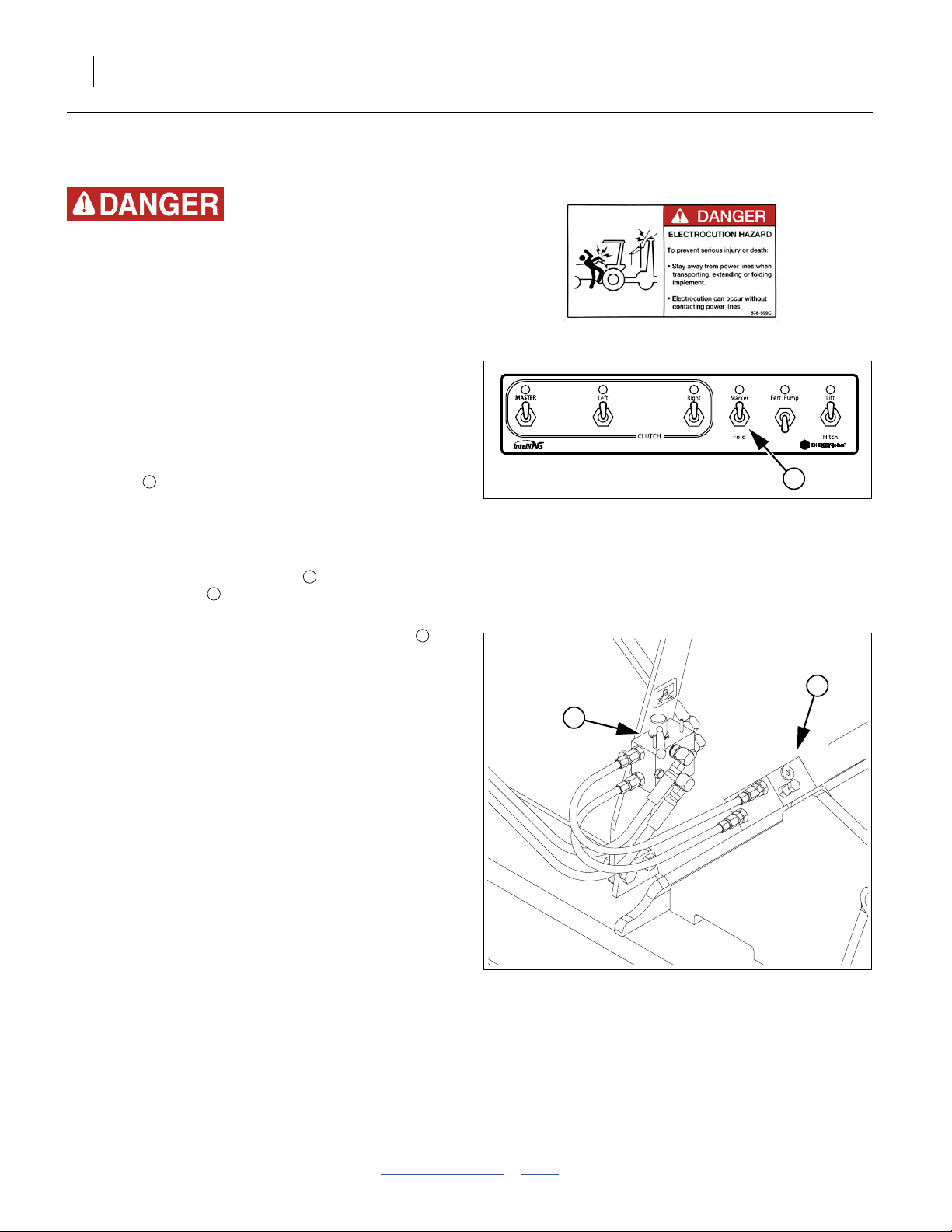
44 YP1125A & YP1625A Table of Contents Index Great Plains Manufacturing, Inc.
Marker Operation
Electrocution Hazard:
Check for overhead lines before operating markers. If a
marker contacts an electrical line, all metal parts of the
planter and tractor can have lethal voltages present. There
may be no indication of this condition until a person completes
the circuit to ground. At higher voltages, electrocution can
occur without direct contact.
Before operating markers, make sure they are properly
bled as described in “Bleeding Hydraulics” on page 97.
For markers to operate, the marker hydraulic circuit must
be enabled:
Refer to Figure 52
1. On the CFM switch panel, set the “Marker/Fold”
switch to Marker. Leave this switch in “Marker”
position for all field operations. It also acts to lock the
folding system when in “Marker”.
Refer to Figure 53
2. If the planter is equipped with an auxiliary hydraulic
system, set the selector valve (found near the
sequence valve at the marker base on the left
wing) to “Marker”.
Dual markers are equipped with a sequence valve to
control lift sequence. Starting with both markers up, the
sequence is:
1. Activate tractor hydraulic lever; right marker lowers
while left marker stays up.
2. Reverse hydraulic lever; right marker raises while left
marker stays up.
3. Activate hydraulic lever; left marker lowers while right
marker stays up.
4. Reverse hydraulic lever; left marker raises while right
marker stays up.
5. Pattern repeats.
Folding speed of dual markers is adjusted with
adjustment screws on sequence valve body. Because
excessive folding speed may damage markers, adjust
markers to a safe folding speed according to “Marker
Adjustments” on page 56.
Note: To get both markers in the lowered position at the
1
2
3
3
same time, activate hydraulic lever to lower one
marker. After marker is lowered, move lever to
opposite position then quickly reverse lever and
hold until other marker is lowered.
Figure 52
CFM: Markers Enabled
2
Figure 53
Aux Valve Set to Markers
1
28491
3
28493
401-625M Table of Contents Index 2013-08-13
Page 49

Great Plains Manufacturing, Inc. Table of Contents Index Operating Instructions 45
Field Operation
Perform all steps in “Pre-Start Checklist” on page 19
and “Field Setup Checklist” on page 36.
PDC: DICKEY-john® Planter/Drill Control manuals
SRM: Seed Rate manual
First Pass Operation Checklist Page
1. Set planting rate. 49
2. Unfold marker on next-row side. 44
3. With tractor at high idle, set fan hydraulic
circuit to low flow, engage circuit. Gradually
adjust fan hydraulic flow to obtain
recommended rpm.
4. Set or verify meter pressurization value. SRM
5. Engage optional hydraulic seed drive via
seed monitor.
6. In the CLUTCH cluster of the CFM, set all
switches, including Master, to ON.
7. Pull forward, lower planter, and begin
planting for a short distance.
8. Stop. Assess:
planting depth,
skips or doubles (see sidebar and page 51),
seed spacing (to verify population),
press wheel operation and
fertilizer application (if in use)
9. Continue planting for at least 10 seconds (so
that the seed monitor is reporting a stable
population number). Verify that it is your
desired rate.
10. Make necessary adjustments 48
PDC
42
38
Note: Use Depth Control mode. If tractor 3-point hitch
control is set for Load Control, hitch movement
may cause changes in row unit depth resulting in
uneven depth control.
Figure 54
CFM: Planting Configuration
Skip and Double Checks
A. Dig up seed (or plant shallow with press wheel tied
up). Check seed spacing against charts.
B. With meters still charged with air, carefully inspect
disks at several rows.
Inspect the arc from just after the top tuft brush to
the bottom edge of the seed drop brush. Look for
cells (seed pockets) having no seed, or more than
one seed. You may need a flashlight to perform this
inspection.
28491
Sharp Field Turns Checklist Page
1. Fold marker 44
2. Raise planter 24
3. Make turn
4. Lower planter 24
5. Unfold marker on next-row side. 44
6. Resume planting.
2013-08-13 Table of Contents Index 401-625M
Suspending Planting Checklist Page
1. Stop tractor
2. Fan hydraulic circuit to Float or Neutral 42
3. Fold Marker 44
4. Raise planter 24
Ending Planting Checklist Page
1. Suspend operations as above, then
2. Fold planter 25
3. Install transport locks 26
4. Lights ON -
5. Transport 28
Page 50

46 YP1125A & YP1625A Table of Contents Index Great Plains Manufacturing, Inc.
Parking
1
For information on long-term storage, see “Storage” on
page 47.
1. If equipped with fertilizer, flush system and secure
pump against corrosion.
2. Fold planter. see “Folding the Planter” on page 25.
Note: Be sure to install cylinder lockup channels. Failure
to do so may result in injury and/or damage to the
planter.
3. Park planter on a level, solid area.
4. To prevent rolling, block tires securely.
Roll-Away Hazard:
DO NOT unhitch planter while on a steep slope. Always block
tires when unhitching from tractor. There is not enough weight
on parking stand(s) to anchor planter on a slope.
Refer to Figure 55
2
3
3 Point Hitch
5. Remove pin holding main parking stand in “UP”
position. Swing stand down. Pin stand in parking
position. If the ground is soft, place a board or plate
under the stand.
6. Remove wire snap lock pin from innermost hole
on park stand mount, or remove both pins if stand
was inverted. Swing support stand from underneath
crossbar weldment, or invert to foot down.
7. Secure 3-point prop stands by using two pins on
each stand.
8. Lower tractor 3-point until planter is resting on
parking stand.
1 2
3
4
Hydraulic Tongue Hitch
9. Remove pin holding main parking stand in “UP”
position. Swing stand down. Pin stand in parking
position. If the ground is soft, place a board or plate
under the stand.
10. Use tongue cylinder to lift planter high enough to
fully swing down parking stand. Insert locking pin in
parking stand.
11. Use tongue cylinder to lower planter onto parking
stand. Pin parking stand.
12. Use tongue cylinder to lift tongue off tractor draw bar.
1 2
4
Figure 55
Jack and 3-Point Prop Stand
Either Hitch
13. Set all implement hydraulic circuits to Float to relieve
pressure in lines.
14. Shut down hydraulics. Unplug hydraulic lines from
tractor. Do not allow hose ends to rest on the ground.
15. Unplug planter light cable from tractor.
16. Unplug monitor harness from console.
17. 3-point: Unhook tractor from planter hitch.
18. Pull tractor away.
22814
27282
401-625M Table of Contents Index 2013-08-13
Page 51

Great Plains Manufacturing, Inc. Table of Contents Index Operating Instructions 47
Storage
Store the planter where children do not play. If possible,
store the planter inside for longer life.
1. Empty hopper (page 90).
2. Close the seed box or hopper door (page 91).
Clean out the air system (page 91).
3. Remove hopper or seed box (page 34).
4. Cover and seal off the opening at the top of the air
box. Leave clean-out door slightly ajar to allow any
condensed moisture to drain off.
5. Remove seed disks from meters (this is primarily to
relieve pressure on brushes). Clean disks of residue
build-up (see Caution at right). Use mild soap,
non-abrasive scrubbers, and hot or warm water. If
using sealed storage, dry disks prior to storage.
6. Close seed inlet shutters at meters (to prevent pest
entry to seed hoses). Thoroughly clean seed and
seed treatment residue from seed meters. See
“Meter Clean-Out” on page 92, for more information.
7. If your planter is equipped with an optional fertilizer
tank, clean tank and application hoses. Be sure to
follow chemical manufacturer’s instructions when
handling chemicals.
8. Thoroughly clean pump following instructions in the
pump manual.
9. Unscrew caps on end of fertilizer booms and flush
them out. Drain completely and replace caps.
10. Remove any dirt and debris that can hold moisture
and cause corrosion.
11. Lubricate and adjust all roller chains.
12. Smear grease on exposed cylinder rods to prevent
rust. Add a brightly-colored tag at the hitch as a
reminder to de-grease the rods prior to next use (to
avoid any risk that congealed grease might damage
seals).
13. See “Lubrication” on page 104, for lubrication
information.
14. Inspect planter for worn or damaged parts. Make
repairs and service during off season.
15. Use spray paint to cover scratches, chips, and worn
areas on the planter to protect the metal.
16. Cover planter with a tarp if stored outside.
Note: Removing the seed box/hopper increases the life
of the air box seals, which are otherwise apt to be
permanently compressed if stored under load
off-season.
Note: Do not store optional bulk hopper outside on the
ground. Raise it on blocks, securing it in place to
prevent from falling over or blowing around by
wind. Store inside if possible.
Possible Chemical Hazard:
Seed disks will have talc and graphite residue, and may have
residues of hazardous seed treatments. Do not wash disks
where food is prepared, or where cookware or dinnerware is
washed. Wear gloves when washing disks. Avoid spray.
Although the disks are dishwasher-safe, do not wash them in
an appliance also used for food cookware or dinnerware.
Storage: Fertilizer Option
The pump, strainer and manifold system require special
attention prior to storage. See “Fertilizer System
Maintenance” on page 102.
2013-08-13 Table of Contents Index 401-625M
Page 52

48 YP1125A & YP1625A Table of Contents Index Great Plains Manufacturing, Inc.
Adjustments
To get full performance from your Planter, you need an
understanding of all component operations, and many
provide adjustments for optimal field results. Some of
these are covered earlier in this manual.
Even if your planting conditions rarely change, some
items need periodic adjustment due to normal wear.
Adjustment Page The Adjustment Affects
Tongue Height 17 Correct draft load to tractor
Frame Leveling 147 Planting consistency
Wing Alignment 148 Correct and consistent row tracking
Clutch Lock-Up 38 Temporary operation with a failed clutch
Air System 40
Fan Speed 43 Optimal seed distribution
Meter Pressurization (values from SRMa)
Planting Rate
Ground Drive Sprockets 49 Meter rpm (seed delivery to seed tube)
Ground Drive Contact Wheel 50 Consistent meter rpm
Hydraulic Drive - Refer to Planter Seed Rate manual
Marker Adjustments
Marker Extension 150 Swath alignment
Disk Angle and Orientation 56 Visibility of mark
Marker Speed Adjustment 56 Reliable marker operation
Height Switch Adjustment 57 Correct off/on state of meter drive
Fertilizer Adjustments (Option)
Fertilizer Rate 55 Refer to Planter Seed Rate manual
Fertilizer Relief Valve SRMaRefer to Planter Seed Rate manual
Fertilizer Orifice Selection SRMaRefer to Planter Seed Rate manual
Frame-Mounted Row Accessories (Options)
Terra-Tine Row Cleaners 58 Row preparation
Coulters 59 Row pre-furrow depth and trash cutting
Vantage I Fertilizer Delivery 59 Fertilizer placement
25 Series Row Unit Adjustments
Row Unit Down Pressure 61 Planting depth uniformity
Row Unit Lock-Up 71 Single/twin-row operation
Row Cleaner Adjustments (Option) 63 Row preparation
Coulter Adjustments (Option) 64 Row pre-furrow depth
Row-Unit Opener Adjustments 65 Seed depth, spacing, coverage
Side Depth Wheels 66 Seed depth
Adjusting Gauge Wheel Scrapers 67 Consistent seed furrow depth
Seed Meter Setup and Adjustment 68 Consistent seed population
Seed Firmer Adjustments (Option) 74 Seed-soil contact
Press Wheel Adjustment 76 Effective soil coverage
Monitor Adjustments - Refer to Seed Monitor manual
a. SRM: Seed Rate Manual (401-625B)
51 Consistent seed flow and disk singulation
401-625M Table of Contents Index 2013-08-13
Page 53

Great Plains Manufacturing, Inc. Table of Contents Index Adjustments 49
Setting Material Rates
Planting Rate
Adjusting the planting rate requires the following:
1. setting seed rate:
For ground-drive planters:
adjusting drive speed Range sprockets, and
adjusting Transmission sprockets,
For hydraulic drive planters, setting monitor and
drive control channel,
2. preparing seed meters, including disks, shutters and
meter pressurization,
3. checking tire pressure.
4. checking planting rate.
Population Target Risk:
Tire pressure matters for both ground and hydraulic drive.
Incorrect tire pressure causes incorrect ground speed readout.
On ground drive, incorrect pressure causes incorrect or
inconsistent seed metering.
TRANSMISSION
RANGE
1
3
4
DRIVEN
Ground Drive Planting Rate
Wing Rate Mismatch Risk:
There are separate left and right contact drives. Each drives
one wing. Sprockets must be set identically on both side, per
decals on each drive.
Refer to Figure 56 and Figure 57
Note: Contact wheels turn in opposite direction from
main ground tires.
Drive Speed Range Sprockets
Select Range sprocket pairing for your seed and rate
from the Seed Rate manual.
Loosen Range idler and remove chain . Remove
retaining pins from shafts and install speed Range
sprockets called for in chart. Additional sprockets are on
storage towers behind the reversing drive plate.
Population Target and Wing Rate Risk:
Make sure the correct sprockets have been installed in the
DRIVING and DRIVEN locations.
Reroute chain over sprockets and idlers as shown.
Transmission Sprockets
Select Transmission sprocket pairing for your seed and
rate from the charts in the Seed Rate manual.
Loosen idler and remove drive chain . Remove
lynch pins from shafts. Install sprockets per chart.
Reroute drive chain over sprockets and idlers as shown.
Move idlers into chains for1⁄4inch (6 mm) slack in the
longest spans. Tighten idlers and re-install lynch pins.
Store and pin removed sprockets on storage towers.
4 5
1
2 3
DRIVEN
1
RANGE
DRIVING
2
DRIVING
5
Figure 56
Left Contact Drive
3
DRIVEN
Figure 57
Right Contact Drive
DRIVING
2
29745
TRANSMISSION
4
DRIVING
5
DRIVEN
29746
2013-08-13 Table of Contents Index 401-625M
Page 54

50 YP1125A & YP1625A Table of Contents Index Great Plains Manufacturing, Inc.
Contact Wheel Drive
Refer to Figure 58
You can adjust the down pressure the contact wheel
exerts by adjusting the pressure on the spring.
Note: Dual contact drive has dual springs to set.
Note: Do not adjust spring so tight that it will bottom out
when raised.
Refer to Figure 59
Before adjusting spring, raise planter and adjust wheel
travel to obtain 11⁄2inch (3.8 cm) clearance above the
main tire.
Refer to Figure 60
You can adjust the amount of travel for the contact wheel
by loosing the jam nuts and lengthening or shortening
the threaded rod.
Note: This adjustment controls the timing of the seed
meter drive when raising and lowering the planter.
Increasing the gap between the tires causes seed
flow to start and stop with the planter at a lower
height. Decreasing the gap will cause seed flow to
start and stop at a higher position.
Note: Be sure to check for spring bottoming after making
this adjustment.
Figure 58
Down Pressure Spring
Figure 59
Contact Drive Wheel
Figure 60
Travel Adjustment
21973
11⁄2inch
22500
21972
401-625M Table of Contents Index 2013-08-13
Page 55

Great Plains Manufacturing, Inc. Table of Contents Index Adjustments 51
Fan and Meter Pressurization Adjustment
1. These steps presume that correct seed disks are
installed (Seed Rate Charts), and the seed inlet
shutters are set for the seed (page 68).
2. With fan off, check meter pressurization reported by
seed monitor. Re-zero as needed (see Seed Monitor
manual).
3. Determine recommended fan rpm based on your
own notes in the Seed Rate Charts, or the table on
page 43.
4. Determine the recommended meter pressurization
based on your own notes or the published value in
the Seed Rate Charts.
5. Start the fan. Gradually increase fan rpm using the
tractor’s hydraulic flow control for the circuit. Adjust to
the developed or suggested value from step 3.
6. Check that at least a small amount of pressure is
being sensed at the meters and meter pressurization
is near suggested value.
7. Perform a “FILL METER” operation for at least one
minute (see DICKEY-john®Planter/Drill Control user
level 1 manual).
8. Check for meter fill:
With fan running, put the tractor in Park and set the
brakes. Walk behind the wings, remove several rain
covers, and check for seed in meters by looking
through the clear disks. Rows to check are those
with longer hoses or sharper hose bends.
9. Fill the disk pockets with seed:
Hydraulic Drive: Run a “FILL DISK” operation.
Ground Drive: See options at right.
10. Check control air system pressure. With meters and
disks filled, meter pressurization should be at target
value.
11. Begin planting. Troubleshoot any obvious problems
or alarms.
The meter pressurization system cannot reach full
operating pressure when the hoses, meters and disks
are completely empty. Low initial pressures are normal.
If a meter runs completely out of seed (“starved”),
back-pressure to the air box manifold may prevent
prompt refill. To fill a starved meter, close the seed inlet
shutter for about 15 seconds, then restore it to the
original setting.
Fill Disk with Ground Drive:
• With CFM clutch switches off, use a7⁄8inch (23 mm)
wrench to rotate the wing meter system drive shaft
11⁄2turns (top forward).
• Lower the planter and plant for a short distance. It
takes a few feet before seed begins to drop from
meters.
2013-08-13 Table of Contents Index 401-625M
Page 56

52 YP1125A & YP1625A Table of Contents Index Great Plains Manufacturing, Inc.
12. During the first pass, take note of the average
populations reported on the seed monitor.
Typical Location: Item:
Screen 1, first row
Average Overall Population
above graphs
If the reported population varies from your intentions
by a significant amount, it is imperative to perform a
furrow check. For serious rate variances, for which
the source of the problem and the solution are not
quickly determined, see “Population
Troubleshooting Charts” on page 79.
If population is only slightly low, the problem can be
skips (periodic empty disk pockets). If slightly high,
the problem can be doubles (periodic pockets with
double seed). A meter pressurization adjustment
may correct either condition (see step 14).
13. Resume planting. During the next pass, note the
following two readouts on the seed monitor:
Typical Location: Item:
Screen 1, 2nd row
Minimum Row Population
above graphs
Screen 1, 3rd row
Maximum Row Population
above graphs
Small seeds, such as Milo, may be under-reported. Use
the “Alternate Skip/Double Check” below to verify
seed status at the disc pockets.
Furrow Check:
Expose several seeds in each of several rows, being
careful not to disturb their relative positions. Measure
and average the distance between seeds. Compare this
to the predicted seed spacing for the population in the
Seed Rate manual.
Any instances of no seed where expected may be a
sign of “skips”. Finding two seeds at the same spot is
clear indication of “doubles”
A small varying population deviation between rows is
normal; however, if a row is consistently running lower
or higher than the other rows, it could indicate a meter
or seed sensor problem that needs attention.
“Population Troubleshooting Charts” on page 79.
14. Skips:
If all else is correct, and the overall average
population is running low (or there are gaps upon
furrow check), the cause may be seeds falling out of
disk pockets before delivery to the seed tube.
Increase meter pressurization to correct this. You
can adjust this with the planter in motion.
Press the “SPLITAIR +” softkey on the seed monitor
console. Wait 5 to 10 seconds for the system to
update, while you continue planting. Continue
making small increase adjustments until the reported
population levels out at the target value.
15. Doubles:
If all else is correct, and the overall average
population is running high (or there are double seeds
upon furrow check), the cause may be two seeds in
some disk pockets at delivery to the seed tube.
Decrease meter pressurization to correct this. You
can adjust this with the planter in motion.
Press the “SPLIT AIR -” softkey on the seed monitor
console. Wait 5 to 10 seconds for the system to
update, while you continue planting. Continue
making small decrease adjustments until the
reported population levels out at the target value.
Insufficient meter pressurization, or unusually rough
fields, can increase the incidence of empty pockets. Be
sure to rule out other causes (such as skipping chains,
meter starvation, incorrect meter disks) before adjusting
meter pressurization to reduce apparent skips.
The suggested increment of change is two presses of
the “SPLIT AIR” softkey, at the factory default value for
change increments.
Excess meter pressurization can increase the incidence
of doubles. Be sure to rule out other causes (such as
incorrect meter disks) before adjusting meter
pressurization to reduce doubles.
401-625M Table of Contents Index 2013-08-13
Page 57

Great Plains Manufacturing, Inc. Table of Contents Index Adjustments 53
Fine-Tuning Meter Pressurization
After several passes, if you are comfortable with the
planter’s operation, you can optimize meter
pressurization. Do this during longer passes, so there
are fewer distractions (and see sidebar regarding Milo).
16. Observe the current overall average population
reported by the monitor.
17. Adjust the meter pressurization down, in discrete
steps, waiting 5-10 seconds between adjustments,
until skips occur (population begins falling below
target). Note the pressure at which skips begin.
18. Restore pressure to the initial value at step 16.
19. Adjust the meter pressurization up, by periodic small
increments, until doubles occur (actual population
begins rising above target). Note the pressure at
which doubles begin.
Note: If unable to adjust up to doubles (or skips happen
instead), seed delivery is probably being starved of
air. Increase fan rpm and repeat limit search.
20. Adjust meter pressurization to a value halfway
between the limits established at step 17 and
step 19. This is the ideal value for your crop, disk and
population, providing equal margin against skips and
doubles. Record this value for future use.
Alternate Skip/Double Check
Small seeds, particularly Milo, are less reliably sensed as
skips or doubles by the seed tube sensors, and watching
monitor population is unlikely to locate the pressure
limits. This test can also be quicker for all seeds.
A. After planting a few passes with initial settings,
remove the rain covers from several rows (use rows
with a variety of seed hose lengths and routes).
B. Make a meter pressurization adjustment. Resume
planting for a pass or less.
C. Stop planter motion but leave fan running.
D. Inspect the seed disks closely. Look for empty seed
cells (skips) and cells with multiple seeds (doubles).
E. Repeat step B-step D until limits are established.
Record limits. Re-install rain covers. Plant with
median settings.
2013-08-13 Table of Contents Index 401-625M
Page 58

54 YP1125A & YP1625A Table of Contents Index Great Plains Manufacturing, Inc.
Checking Planting Rate
Cautious practice includes checking seed delivery rate
prior to planting.
Although the seed monitor can count most singulated
seeds, it may not reliably count the smallest (such as
Milo), it does not count individual volumetric seeds, and
several factors can cause even large seed singulated
reports to be inaccurate (such as incorrect speed
calibration, Sensor Constant or Gear Ratio setup).
Methods of rate checking are described in detail in the
Seed Rate Manual. The information on this page is an
overview of the general process, which varies with the
seed type and the planter meter drive type.
Before checking rate, make sure that the seed monitor is
configured with an accurate Ground Speed Constant. As
delivered, the monitor may have an inappropriate value
pre-loaded.
The DICKEY-john® Quick Start Guide for your planter
includes an initial value for this constant, but this value
may not be optimal for your planter, and does not include
any adjustment for tire wear over time.
For reliable monitor reports, at the start of each season,
perform a “GROUND SPEED CALIBRATION” over a
400 foot/100 m course, as described in the
DICKEY-john®IntelliAg®Planter/Drill Control Operator’s
Manual. When completed and entered in the monitor,
cross-check the reported implement speed against the
tractor speedometer or other reference.
Checking Singulated Rate
A furrow check is the most accurate way to verify that
you are seeding at your desired population value. This is
done by planting for a short distance with one or two
rows set to shallow depth and with press wheels tied up
for no furrow closure. Seeds are counted in the furrow
over a specific distance and the area rate is computed.
Refer to the Seed Rate Manual for details.
The seed monitor will also be counting during the test,
and comparing results provides confidence in the seed
monitor display.
Note: If the checked rate varies materially from the chart
rate, or for hydraulic drive, from the programmed
rate, it is likely that there is a seed flow problem or
planter malfunction (such as contact drive tire
slippage) or a configuration error that requires
correction. Do not “calibrate” to correct unexpected
variations in singulated rates.
401-625M Table of Contents Index 2013-08-13
Page 59
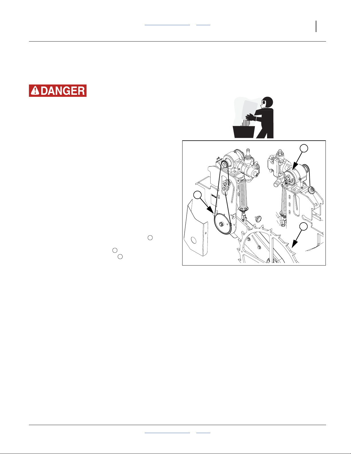
Great Plains Manufacturing, Inc. Table of Contents Index Adjustments 55
Setting Fertilizer Rate
This page is an overview. For details on fertilizer rate
setting, refer to the Seed Rate Manual, 401-625B.
Possible Chemical Hazard:
Wear proper protective equipment as required by chemical
manufacturer. Avoid breathing of chemical fumes. Wear
respirator as required by chemical manufacturer. Seek medical
assistance immediately if accident occurs. Some chemicals
cause serious burns, lung damage, and death. Avoid contact
with skin or eyes. Know what to do in case of an accident.
Fertilizer rate is controlled by pump rate (for the Great
Plains ground drive pump). Consistent delivery across
the planter is controlled by orifice size at row unit
drop-line points.
Consistent system operation also requires a correctly
adjust relief valve and a well-maintained strainer ahead
of the pump. See “Important Safety Information” on
page 1 and “Important Safety Information” on page 1.
2
3
Piston Pump
The liquid fertilizer option uses a piston pump. For pump
operation and pump maintenance refer to the pump
manual, supplied in the liquid fertilizer option package.
The pump is driven by a ground contact wheel , and
fertilizer rate is independent of seed rate. Coarse
fertilizer rate is set by a sprocket on the ground drive
assembly. Fine rate is set by a dial on the pump. For
settings, see the Seed Rate manual.
Note: Great Plains recommends checking with your local
Agronomist, as soil conditions vary. Conditions in
your area may need lesser or more amounts of
fertilizer than represented in these charts. Do not
exceed 12 gallons per acre (112 liters/ha) in any
case.
Note: Always disable the pump drive when not in use.
Use ground contact wheel lock up if installed. On
older models remove the chain. Do not operate
planter pump when not applying material.
2
3
1
Figure 61
Ground Drive Pump
1
28494
2013-08-13 Table of Contents Index 401-625M
Page 60
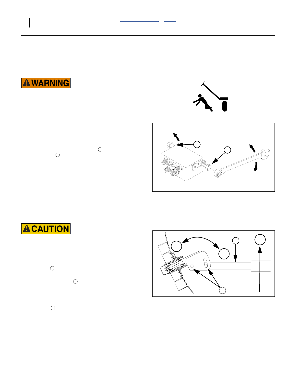
56 YP1125A & YP1625A Table of Contents Index Great Plains Manufacturing, Inc.
Marker Adjustments
See also:
“Marker Setup” on page 150 and,
“Marker Maintenance” on page 98.
Pinch, Crush and Sharp Object Hazards:
Never allow anyone near the planter when folding or
unfolding the markers. You may be injured if caught or struck
by a folding or unfolding marker. Markers may fall quickly and
unexpectedly if the hydraulics fail.
Dual Marker Speed Adjustment
Refer to Figure 62
Adjust folding speed for dual markers with hex
adjustment screws on sequence valve body. There is an
adjustment screw for raising speed and one for
lowering speed . You can identify adjustment screws
by markings stamped in the valve body.
Turn adjustment screws clockwise to decrease folding
speed and counterclockwise to increase folding speed.
With tractor idling at normal operating speed, adjust
marker folding to a safe speed. Excessive folding speed
could damage markers and void the warranty.
After adjusting folding speed, tighten jam nuts on hex
adjustment screws to hold settings.
2
1
S
2
Figure 62
Marker Extension Adjustment
F
1
S
14048
Marker Disk Adjustment
Sharp Object Hazard:
Use caution when making adjustments in this area. Marker
disks may be sharp.
Refer to Figure 63
To change angle of cut, and the width of the mark, loosen
1
⁄2-inch bolts holding disk assembly.
For a wider mark (W), increase the angle of the marker
with respect to the tube . For a narrower mark (N),
reduce the angle.
You can also invert the disk blade on the hub to change
the direction of throw.
Tighten bolts .
Note: The direction of travel (T) tends to drive the disk
angle to Wide. If bolts are not tight enough, or
loosen over time, the disk will slip into the Wide
mark configuration.
6
5
6
W
N
6
Figure 63
Marker Disk Angle
5
T
11757
401-625M Table of Contents Index 2013-08-13
Page 61

Great Plains Manufacturing, Inc. Table of Contents Index Adjustments 57
Height Switch
The height switch informs the seed monitor about the
lowered/raised status of the planter. On all planters, the
monitor only counts seed when the activate the Drive
when the planter is lowered. On hydraulic drive planters,
the switch also enables or disablesa hydraulic drive.
Refer to Figure 64
1. Loosen the bolts holding the height switch bracket
and rotate the switch and bracket away from the
frame pivot .
2. Lower the planter to the height at which seed
delivery should begin.
3. Rotate the switch towards the frame pivot until the
spring actuator just touches the frame.
4. Rotate the switch in until it clicks. Tighten the bolts to
secure it in place. Be sure frame tube will not crush
switch when unit is fully loaded.
Note: It may be necessary to loosen the screws holding
the switch and rotate the switch slightly on the
bracket.
1
1
3
4
4
2
1
2
3
Figure 64
Height Switch
23398
a. When a hydraulic drive planter is raised, the switch state is ignored during “FILL DISK” and “5 REV TEST” operations.
2013-08-13 Table of Contents Index 401-625M
Page 62
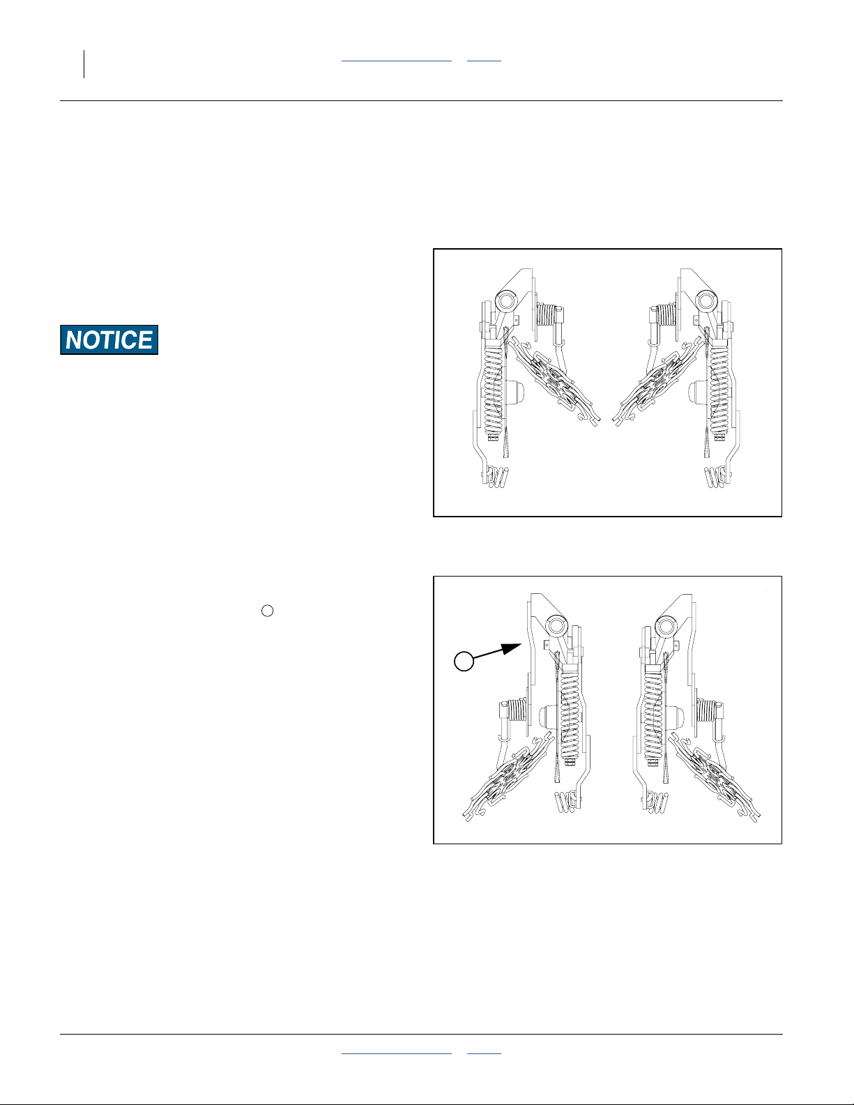
58 YP1125A & YP1625A Table of Contents Index Great Plains Manufacturing, Inc.
Row Implement Adjustments
To get full performance from your planter, you need a
good understanding of row cleaner, coulter, fertilizer,
opener, meter, seed firmer, and press wheel operation.
Frame-Mounted Row Accessories
Terra-Tine™ Adjustment
Refer to Figure 65
Note: All adjustments must be made with the unit in the
fully raised position.
Excess Wear Risk:
Check that the Terra-Tine Row Cleaner tines DO NOT touch
the coulter blade or any other attachments. At least1⁄2inch
(13 mm) clearance is recommended. Tine contacts cause
excess wear to all parts involved.
1. When the blade is out of the soil, adjust the lock
collar height to set the height of tine fingers flush with
the bottom of coulter blade.
2. Side-to-side alignment can be done by rotating the
shank mount around the vertical shaft and
retightening the square head set screw.
L.H.
Figure 65
Terra-Tine in Front of Hub
R.H.
13469
Refer to Figure 66
3. Fore-to-aft adjustment is accomplished by adding or
removing the extension arm to place the
Terra-Tine Row Cleaner to either side of the coulter
hub depending on the desired position or clearance
between other attachments. Testing has shown
better performance behind the hub, but available
space may dictate the mounting position.
1
1
L.H.
Figure 66
Terra-Tine Behind Hub
R.H.
13469
401-625M Table of Contents Index 2013-08-13
Page 63

Great Plains Manufacturing, Inc. Table of Contents Index Adjustments 59
Frame-Mounted Coulters
Refer to Figure 67
At the shaft , adjust the coulter depth for a running
depth of 4 to 41⁄2inches (10.2 to 11.4 cm) below
ground level if off row, if on row as a no-till coulter
operate at planting depth only . Refer to the Vantage I
manual (204-376M) for further adjustments.
Do not adjust the spring tension. It is factory pre-set.
1
2
3
4
1
4
3
2
Vantage I Applicator
Refer to Figure 68
At the back plate , adjust the tine height for a running
6 3
depth of 1 inch (2.5 cm) below ground level . Refer
to the Vantage I manual (204-376M) for further
adjustments.
5
Figure 67
Frame-Mount Coulter
5
Figure 68
Vantage I Applicator
25392
6
3
22951
2013-08-13 Table of Contents Index 401-625M
Page 64

60 YP1125A & YP1625A Table of Contents Index Great Plains Manufacturing, Inc.
25 Series Row-Unit Adjustments
Refer to Figure 69, which depicts a 25 Series row unit
populated with most options supported on YP1225A &
YP1625A (excepting scrapers and Seed-Lok®)
1. Lock-Up Pin Storage Hole (hole Standard)
See “Row Unit Shut-Off” on page 71.
2. Down-Pressure Cam (Standard)
Row units are mounted on parallel arms. This
parallel-action mounting allows the row-unit to move
up and down while staying horizontal. Springs add
an adjustable force, set by the cam, to the row
weight. See “Row-Unit Down Pressure” on
page 61.
3. Meter Pressurization Air Inlet (Standard)
Pressure-regulated air enters the meter here and
holds seed in the disk pockets. See “Fan and Meter
Pressurization Adjustment” on page 51.
4. Seed Delivery Hose Inlet (Standard)
Air carrying the bulk seed is vented at the bottom of
the air release cone. Gravity then carries the seed
into the meter at the shutter . The hose is easily
removed for inspection. There are no adjustments.
5. Air-Pro
See “Air-Pro® Meter Disk Installation” on page 70.
6. Seed Inlet Shutter (Standard)
This controls the level of bulk seed at the disk. There
are four operating settings, plus fully open
(clean-out) and fully closed (shut-off or storage). See
“Seed Inlet Shutter Adjustment” on page 68.
7. Side Gauge Wheel Depth (Standard)
The T-handle sets planting depth by controlling the
height of the side gauge wheels relative to the
opener discs. See “Side Gauge Wheel
Adjustments” on page 66.
8. Press Wheel Force, Angle, Stagger (Standard)
The press wheels close the furrow, gently pressing
the soil over the seed to ensure good seed to soil
contact for even emergence. See “Press Wheel
Adjustments” on page 76.
9. Row Unit Lock-Up Hole (Hole Standard)
Pins are standard on some models. With the row unit
raised above level, the lock-up pin is inserted here.
See “Row Unit Shut-Off” on page 71.
10. Row Cleaner (Option)
Row cleaners clear trash from the row, to a depth set
by an adjustment on the arms. See “Unit-Mount
Cleaner Adjustments” on page 63.
®
Seed Meter (Standard, Choice of Disks)
6
2
1
4
3
5
6
9
7
13
10
11. Unit-Mount Coulter (Option)
Coulters cut remaining trash and begin opening the
seed furrow. Working depth is set by row depth and a
mounting hole selection. See “Unit-Mounted
Coulter Adjustments” on page 64.
12. Opener Discs (Standard)
Row-unit double disc openers create the seedbed
furrow. They have adjustments for angle and
spacing. See “Row-Unit Opener Disc
Adjustments” on page 65.
13. Scrapers (Optional, not shown)
Inside scrapers require no adjustment. For gauge
wheel scrapers, see “Adjusting Gauge Wheel
Scrapers” on page 67.
14. Seed Firmers (Seed Flap Standard, not shown)
An optional seed firmer (Keeton® shown) minimizes
seed bounce and improves soil contact. It may also
deliver fertilizer. See “Seed Firmer Adjustments”
on page 74.
15. Press Wheel Type (Choice)
A variety of single and dual press wheel assemblies
are available, some region-specific. Consult your
Great Plains dealer.
12
11
25 Series Air-Pro® Row Unit
14
Figure 69
15
29600
8
401-625M Table of Contents Index 2013-08-13
Page 65

Great Plains Manufacturing, Inc. Table of Contents Index Adjustments 61
Row-Unit Down Pressure
Row-unit springs provide the down pressure necessary
for row-unit discs to open a seed trench. The springs
allow the row-units to float down into depressions and up
over obstructions. Springs also provide down force on
coulters when using optional row mounted coulters.
You can adjust down pressure individually for each
row-unit. This is useful for penetrating hard soil and
planting in tire tracks. For best results always adjust
tractor tires so they are not ahead of 30 inch or 70 cm
rows.
Use only enough down pressure to cut the seed trench
and maintain proper soil firming over seed. Excessive
row-unit down force will lead to premature wear on
row-unit components. Excessive down force will also
cause uneven seed depth.
Refer to Figure 70 through Figure 72
To adjust down pressure, use 11⁄8inch (29 mm) open
end wrench or tool stored under the walkboard.
Position wrench on nut and pull back and down. Move
adjustment cam to new setting. If using cast tool
stored under the walkboard, be sure row unit is off the
ground to fully relax springs.
Minimum and maximum settings are indicated by
position of adjustment cam. Each notch on adjustment
cam will increase the down pressure on the row-unit
springs. Use the table below as a setting reference.
Note: Do not set all rows any higher than notch 4. Using
settings above this on all rows will create uneven
depth control and improper function.
1
2
3
1
Figure 70
Row Unit Cam Operation
2
3
Figure 71
Cam Minimum Setting (1)
3
29605
27065
Spring Down Pressure
Cam Notch Pounds Kilograms
zero (out of notch) Lock-Up & Maintenance
one 320 145
two 355 160
three 385 175
four 435 200
five 485 220
six 535 245
tip Do Not Use
Individual rows may be set higher if running in heavy tire
tracks.
2013-08-13 Table of Contents Index 401-625M
Cam Maximum Setting (6)
Figure 72
27065
Page 66
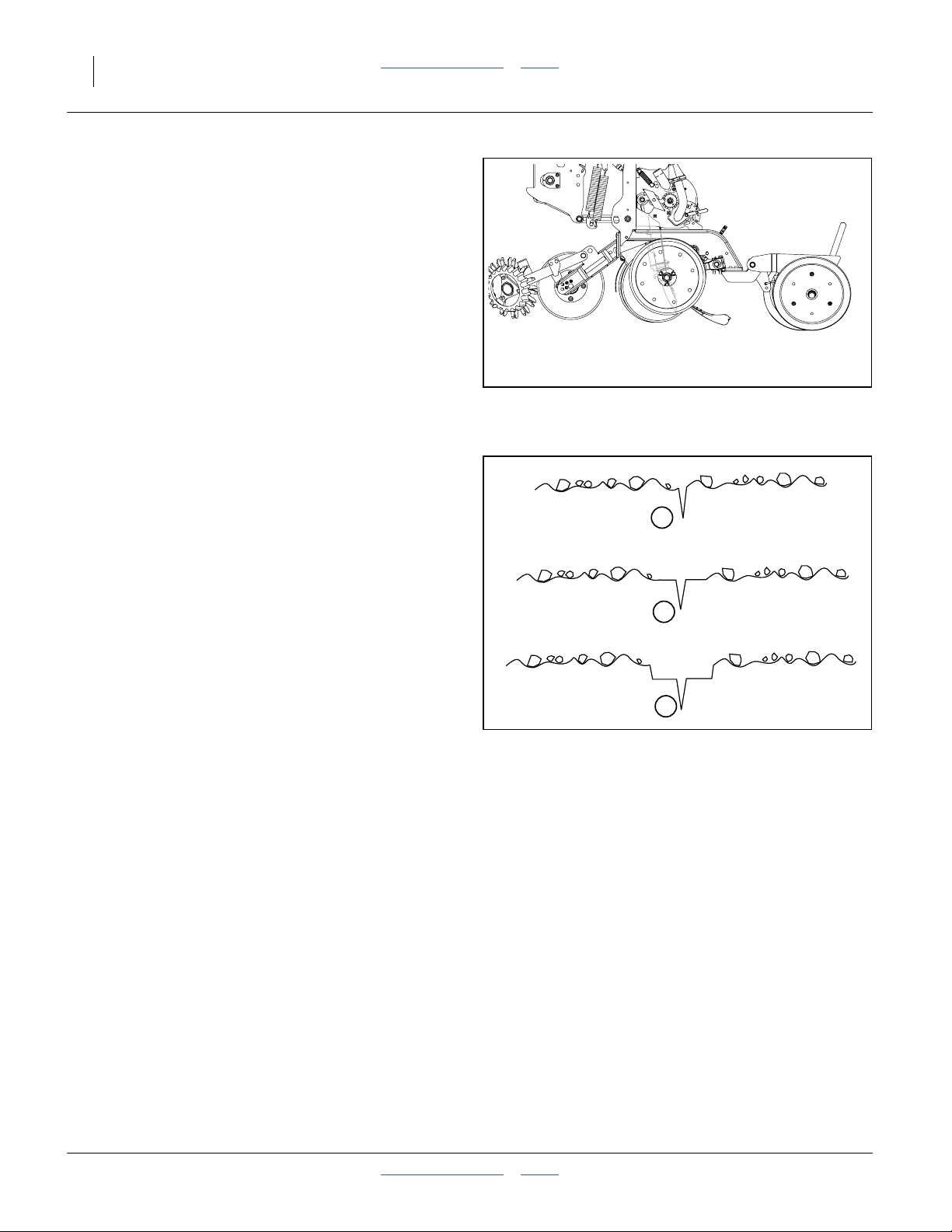
62 YP1125A & YP1625A Table of Contents Index Great Plains Manufacturing, Inc.
Refer to Figure 73
The ideal amount of down-force causes the side gauge
wheels to compress any loose surface soil, but not press
a trench into subsoil.
To assess down-force, operate the planter for a short
distance on typical ground (with or without seeding), and
stop. Leave the planter lowered (row units in ground).
At several row units, inspect the furrow created by the
opener discs, but prior to furrow closing by the press
wheels.
Note: Be sure to inspect rows both in and out of tire
tracks.
Refer to Figure 74
1. If the side gauge wheels are leaving no tracks, or
light tracks, increase down-force.
2. If the wheels are compressing trash and loose soil,
and leaving clear tracks right at the top of the
subsoil, down-force is probably correct and needs no
adjustment.
3. If the wheels are creating a trench into the subsoil,
down-force is too high and needs to be reduced.
Figure 73: 25 Series:
Checking Furrow
Light or no side gauge
wheel tracks
Gauge wheels compress
loose soil only
Inspect Furrow Here
Insufficient down-force
Increase down-force
1
Ideal
No adjustment required
2
{
29600
Side gauge wheels
making deep tracks
Figure 74: 25 Series:
Assessing Down-force
Down-force too high
Reduce down-force
3
401-625M Table of Contents Index 2013-08-13
Page 67

Great Plains Manufacturing, Inc. Table of Contents Index Adjustments 63
Unit-Mount Cleaner Adjustments
Refer to Figure 75 and Figure 76
Optional Martin row cleaners are unit-mounted, using:
UMRC: Unit-Mount Row Cleaner (stand-alone), or
UMC-RC: Unit-Mount Coulter RC (on coulter bracket,
with or without a coulter disc present).
There are two adjustments:
1. Wheel placement (forward or aft mounting hole, for
more or less aggressive cleaning), and
2. Wheel height, adjusted by a stop. Cleaner arms
float. The stop only sets the lowest position.
In UMRC mount, a pinned cross-tube on the mount
adjusts the depth. In UMC-RC (coulter) mount, a sliding
down-stop block adjusts how close to the ground the
row cleaners operate.
The row cleaner needs to be adjusted for your
conditions, crop changes, and as coulters and openers
wear. Ideally, cleaners contact only the trash, and do not
disturb the soil. If allowed to “dig”, row cleaners can
reduce seed coverage.
Suggested initial depth is tine tips at ground level.
Make the adjustment with the planter raised. Install
lift-assist cylinder locks. Also check bolt tightness prior
to each planting session, to avoid down-stop slippage.
To adjust the row cleaner:
1. Determine the height adjustment required. Measure
from the lowest tine to the ground. Determine the
desired new measurement.
2. Support most or all of the weight of the arm to
prevent injury and ease the adjustment. Loosen
5 2
bolts on UMC-RC. Remove bent pin on UMRC.
3. Support arm at desired height.
4. UMRC: Slide adjustment tube until cross-tube
contacts arm at target height. Insert bent pin in
whichever hole pair is most in alignment.
5. UMC-RC: Slide the down-stop on the arm :
- back toward the pivot for shallower cleaning, or
- forward toward the tines for deeper cleaning.
Tighten the bolts . Each possible hole pairing
adjusts the tine height by about3⁄4inch (19 mm).
6. Check the new height measurement.
Refer to Row Cleaner manual 204-085M-A for further
information on use, adjustment and maintenance of row
cleaners.
6
5
3
5
1 3
2
6 4
Sharp Objects Hazard:
Wear hand protection when working in this area. Row cleaner
tines, casting edges and coulter blades are sharp.
UMC-RC: Row Cleaner Adjust
1
2
Figure 75
UMRC: Cleaner Adjust
5
6
Figure 76
3
27308
4
27343
2013-08-13 Table of Contents Index 401-625M
Page 68

64 YP1125A & YP1625A Table of Contents Index Great Plains Manufacturing, Inc.
Unit-Mounted Coulter Adjustments
The ideal operating depth for coulters is1⁄4inch (6 mm)
above opener depth. Although they may have originally
been set to this depth, coulter (and opener) blades wear
with time, and may need adjusting.
Adjusting the coulter depth is accomplished by
re-mounting the coulter blade in one of the six mounting
holes arranged in a staggered pattern in the coulter
bracket.
Refer to Figure 77 and Figure 78
Raise planter and install cylinder locks before working on
coulters. Row unit may be fully lowered or locked up. Do
not attempt to move blade when the current or new
position causes it to contact the ground during
adjustment. Be careful around the front end of row units.
Row clear tines and coulter blades may be sharp.
To adjust coulter depth:
1. Dismount row cleaner (if present) to reduce risk of
injury.
2. Determine the present opener and coulter depths.
3. Note which bracket hole the coulter is presently
using.
4. Determine which new hole will position the coulter
closer to the1⁄4inch-above depth. See the table
below. If none, don’t move it.
5. Remove the5⁄8-11×4in bolt, lock washer and
7
nut ( in Figure 77).
6. Move the blade to the new position. Insert the bolt,
and tighten on the lock washer and nut.
Figure 77
25 Series Unit-Mounted Coulter
2
3
5
1
4
6
7
29124
Hole
Number
2
3
5
1
4
6
7. Re-adjust openers, if installed.
If a worn coulter cannot be adjusted to satisfactory
operating depth, replace coulter blade.
401-625M Table of Contents Index 2013-08-13
Depth of (new) coulter blade
relative to (new) opener blades
1 inch (25 mm) above
5
⁄8inch (16 mm) above
1
⁄4inch (6 mm) above
0
3
⁄8inch (9.5 mm) below
3
⁄4inch (19 mm) below
Figure 78
Coulter Blade Mounting Holes
23288
Page 69

Great Plains Manufacturing, Inc. Table of Contents Index Adjustments 65
Row-Unit Opener Disc Adjustments
25 Series openers have three adjustments:
1. planting/seed depth
2. opener disc to disc clearance
3. gauge wheel/opener disc clearance
Setting Planting Depth
Refer to Figure 79
The “T” handle sets planting depth by limiting the how
high the side depth gauge wheels ride relative to the
opener discs. The position of the seed tube itself is fixed
relative to the discs, and is not adjusted.
To adjust seed depth, pull the “T” handle up and back,
move it forward or aft, and set it back in a different pair of
holes in the scale.
• For shallower planting, move the “T” handle
forward.
• For deeper planting, move the “T” handle back.
Opener Disc Contact Region
Refer to Figure 80
Opener disc angle and stagger is not adjustable, but
disc-to-disc spacing is, and may need attention as discs
experience normal wear. Spacers will need to be reset
when blades are replaced.
The ideal spacing causes the blades to be in contact for
about one inch . If you insert two pieces of paper
between the blades, they should slide to within zero
(touching) to 1.5 inches (3.8 cm) of each other. If
touching, the gap between the blades should not be
significantly greater than the thickness of two sheets of
paper.
If the contact region is significantly larger or there is a
large gap, it needs to be adjusted by moving one or more
spacer washers.
Adjusting Disc Contact
Refer to Figure 80 and Figure 81
1. Raise the planter and install lift cylinder locks.
2. Remove the side gauge wheels on the row unit in
need of adjustment.
3. Remove the bolt retaining the opener disc on
one side. Carefully remove the disc. Do not lose the
hub components and spacer washers , .
4. To reduce the spacing between the discs (the normal
case), move one spacer washer from the inside to
the outside of the disc.
5. Re-assemble and check disc contact.
1
1
1
1
1
2
3 4
5 6
5
6
Figure 79
Opener Adjustments
1
Figure 80
Opener Disc Contact Region
5
4
Figure 81
Opener Disc Spacers
1
3
2
29600
2
26127
6
3
26128
2013-08-13 Table of Contents Index 401-625M
Page 70

66 YP1125A & YP1625A Table of Contents Index Great Plains Manufacturing, Inc.
Side Gauge Wheel Adjustments
Refer to Figure 82
The side gauge wheels have two, interrelated
adjustments:
• angle of side gauge wheel, and
• distance between side gauge wheels and discs.
Refer to Figure 83
Adjust side-gauge-wheel angle so wheels contact
row-unit discs at the bottom of wheel at 2in planting
depth and gaps open3⁄8to5⁄8inches (9.5 to 16 mm) at
top. Check with row-units in soil so wheels are held up.
At the same time, keep side gauge wheels close to
opener discs so openers do not plug with soil or trash.
However, wheels should be out far enough so discs and
wheels turn freely.
Refer to Figure 84
To adjust side gauge wheels:
1. Raise planter slightly removing weight from side
gauge wheels.
2. Loosen hex-head bolt . Move wheel and arm out
on o-ring bushing.
3. Loosen pivot bolt . Turn hex adjuster so
indicator notch is at 5 o’clock to 7 o’clock.
Note: Use this as the starting point for adjustment.
4. Move wheel arm in so side gauge wheel contacts
row unit disc. Tighten hex-head bolt to clamp arm
around bushing and shank.
5. Check wheel-to-disc contact at 2 inches (5 cm)
planting depth. Lift wheel 2 inches (5 cm) and
release. When let go, wheel should fall freely.
• If wheel does not contact disc at bottom to area where
blade leaves contact with soil, move hex adjuster until
wheel is angled for proper contact with disc.
• If wheel does not fall freely, loosen hex-head bolt
and slide wheel arm out just until wheel and arm move
freely. Retighten hex-head bolt per grade:
1
⁄2inch Grade 5 bolt, 76 foot-pounds (105 N-m).
1
⁄2inch Grade 8 bolt, 110 foot-pounds (150 N-m).
6. Keep turning hex adjuster and moving wheel arm
until the wheel is adjusted properly. When satisfied,
tighten pivot bolt to 110 foot-pounds.
Note: Use “End of “Appendix A - Reference
Information”.” on page 140 for reference.
4
1
2 3
1
1
1
2
Side Gauge
Wheel
Incorrect
Disc/Gauge Wheel Alignment
Opener-Gauge Wheel Contact
1
Starting Point
Disk/Gauge Wheel Adjustment
Opener
Discs
Correct
Figure 82
Contact Within this Area
Figure 83
1
4
4
Figure 84
Side Gauge
Wheel
22531
3
2
22524
22525
401-625M Table of Contents Index 2013-08-13
Page 71

Great Plains Manufacturing, Inc. Table of Contents Index Adjustments 67
Adjusting Gauge Wheel Scrapers
Refer to Figure 85
Scrapers are optional, and may be useful in moist or
sticky soils that tend to accumulate on gauge wheels and
reduce intended planting depth.
To adjust scrapers:
1. Loosen nut .
2. Slide scraper toward gauge wheel until scraper
5
6 7
touches tire.
3. Slide scraper away from wheel leaving a
1
⁄8inch (3 mm) gap at .
6 7
8
4. Rotate scraper left and right around bolt, making
sure it cannot touch tire if bumped in field. If it can
touch tire, back scraper away from wheel until it
cannot.
5. Center scraper angle on bolt until gap is
5 8
constant.
6. Tighten nut .
5
5
8
7
Figure 85
Gauge Wheel Scraper Adjustment
6
25273
2013-08-13 Table of Contents Index 401-625M
Page 72

68 YP1125A & YP1625A Table of Contents Index Great Plains Manufacturing, Inc.
Meter Adjustments
There are adjustments for seed inlet, and choice of disks.
There are no other adjustments, in particular no brush
adjustments, at the meter.
Meter Rain Cover
The rain cover keeps side winds from unseating seed in
disk pockets. It also keeps precipitation, sunlight and
field debris out of the meters.
Refer to Figure 86
To remove the rain cover, peel the flexible snap latches,
at top and rear , away from the meter housing. Pivot
the cover forward and down at tab in slot.
When removing a cover, inspect it for damage and
missing parts. If a cover does not have both latches, and
an intact edge seal under the latches, the cover is apt to
be lost during transport or field operations.
To replace a latch, temporarily remove the seal near the
latch. Slide the replacement latch onto the cover lugs
from the meter side, then snap the other end down over
the lugs. Re-install the seal.
Seed Inlet Shutter Adjustment
Refer to Figure 87 (showing the shutter at setting 3)
The seed inlet shutter regulates the volume of bulk seed
presented to the seed disk. The operating settings vary
with crop, seed size and treatments. The shutter also has
settings for row shut-off (completely closed), and
clean-out (wide open).
The Seed Rate Charts include suggested initial shutter
settings. Refine these settings based on experience, and
on inspection of the slope of the seed pool at the bottom
of the seed disk.
The shutter is operated by a handle. Lift the handle away
from the meter plate. Move the handle to half a setting
higher than the new setting, then back to the new setting,
and lower the pawl into that slot.
The table at right is a general summary of shutter
settings.
1 2
3
2
Setting Setting Typically Used For
Top (0) Closed: Row Shut-Off, Meter Re-Fill
| (1) Small seeds, such as Milo, with little or
|| (2) Small treated seeds and edible beans
||| (3) Corn, round popcorn
|||| (4) Large corn, or heavily treated corn
Bottom (5) Wide Open: Clean-Out
1
Figure 86
Rain Cover Removal
Figure 87
Seed Inlet Shutter
(such as Soybeans)
3
29606
0
|
II
III
||||
5
29607
no treatments
401-625M Table of Contents Index 2013-08-13
Page 73
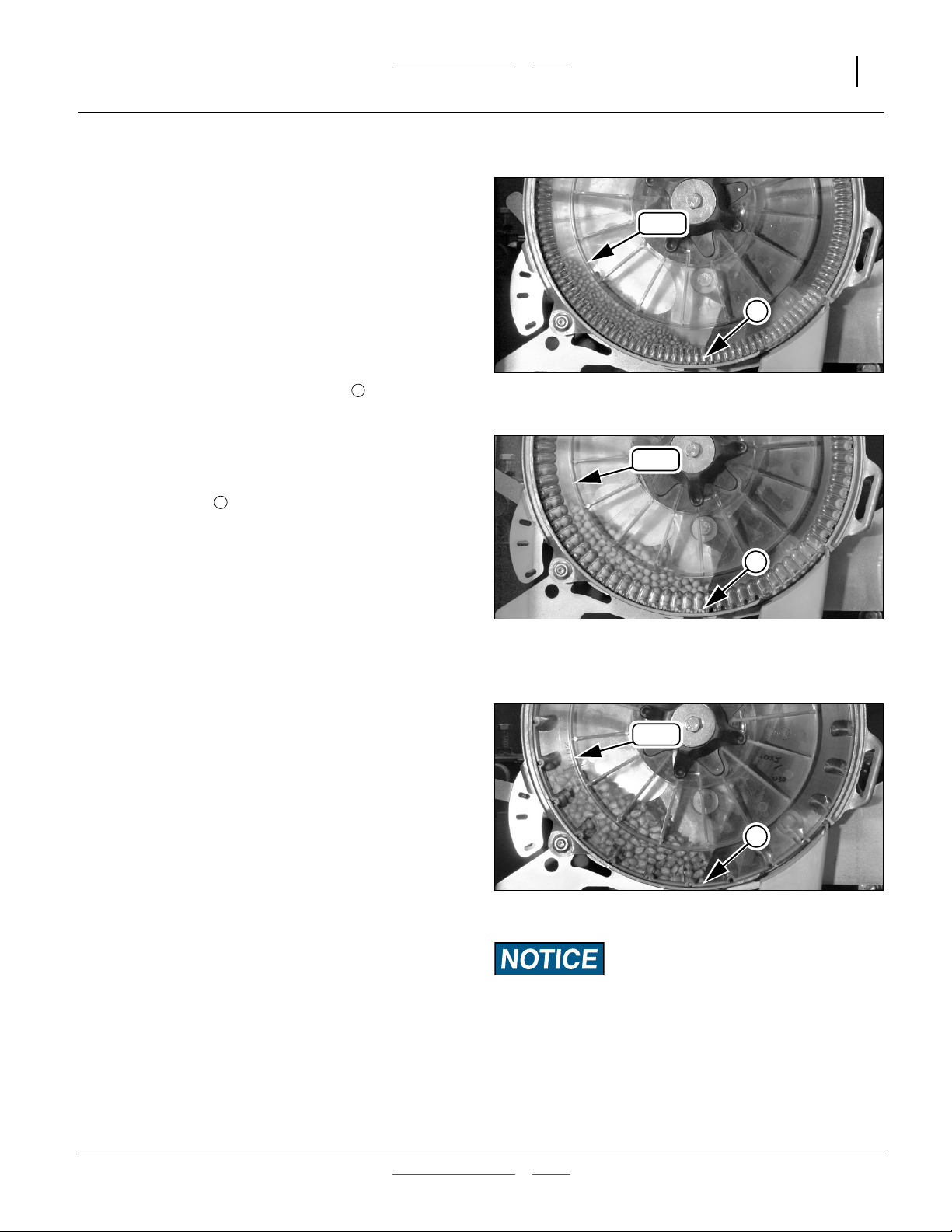
Great Plains Manufacturing, Inc. Table of Contents Index Adjustments 69
Optimal Seed Pool Slopes
The optimal seed slope is one that results in the most
consistent seeding, with minimal skips and doubles.
The column at right has photographs of pool slopes
found to be optimal for representative seeds.
If the suggested initial shutter settings do not seem to be
working for your seed, adjust the shutter to achieve
specific reserve slope targets.
Refer to Figure 88
For medium size and smaller seeds that flow easily, the
slope runs from just above the 8:00 (o’clock) position on
the housing wall, forward and down to one or two seeds
deep at the base of the rear strip brush .
Refer to Figure 89 and Figure 90
For medium size and larger, or heavily treated smaller
seeds that flow less easily, the slope runs from at or
slightly above the 8:30 (o’clock) position on the housing
wall, forward and down to 3-6 seeds deep at the base of
the rear strip brush .
In general, the seeds at the base of the strip brush need
to be deep enough that no air escapes there, and so that
just enough seeds are present to begin populating cells.
Keep the top left/rear end of the pool below the 9:00
o’clock position (meter horizontal center-line).
Meter Re-Fill
Once planting is underway with the seed pools set, it is
infrequently possible for bridging at or above the inlet to
starve the meter of seed.
A completely empty meter causes seed monitor
“Row Failure” alarm, with a report of the row number[s]
involved. Row numbers are counted from the left wing
(outside row is row 1).
Stop, and put the tractor in Park. Leave the fan running.
Locate the failed row, remove the rain cover, and verify
that the meter is empty. Note the shutter setting.
Temporarily open the shutter one of two notches wider. if
the problem was inlet bridging, seed should flow into the
meter immediately.
If inlet bridging is not the problem, little or no seed flows
into the meter with the shutter open wider. In this case,
the problem is further upstream in the seed flow, and
may be bridging at the air release screen at the top of the
meter. Close the shutter completely for about 15
seconds. This prevents meter pressurization air from
opposing seed delivery air. The delivery air pressure
usually collapses the bridge. Re-open the shutter and
see if seed now fills the meter.
If no obvious foreign object was the cause of the
bridging, the shutter setting may have been too small for
the seed. Verify that this and other operating rows were
at the correct initial shutter setting. If so, re-set the
shutters to the next higher opening.
1
1
Milo: Seed Inlet Shutter at: 1
Soybeans: Seed Inlet Shutter at: 2
Corn: Seed Inlet Shutter at: 3
Foreign Object Risk:
After clearing a bridge, or a delivery blockage upstream, check
the seed pool at the meter for any debris that might have been
the original cause. Remove such debris from the meter before
planting. Don’t run the risk of an object lodging in a seed
pocket and causing on-going skips.
8:00
Figure 88
8:30
Figure 89
8:30
Figure 90
1
29602
1
29604
1
29603
2013-08-13 Table of Contents Index 401-625M
Page 74

70 YP1125A & YP1625A Table of Contents Index Great Plains Manufacturing, Inc.
Air-Pro® Meter Disk Installation
1. Cross-check Seed Rate Chart data against part
number/description molded into disks to be used.
Population Risk:
Use the same disk in all active rows.
2. Inspect disks to be installed. Do not install damaged
or excessively worn disks. Either can cause irregular
seeding. Chips and cracks accelerate brush wear.
3. Remove meter rain cover (page 68).
Refer to Figure 91 (depicting an empty meter)
4. Inspect meter (see page 94 for details).
5. Make sure clamp is aligned with seat .
Refer to Figure 92
6. With the seed pocket side facing the meter housing,
place the new seed disk on the disk seat.
7. Rotate disk clamp clockwise 45deg to clamp disk.
Clamp seats into detents in disk hub.
Note: On a new meter, or with new brushes installed,
force the disk into the brushes to allow the disk
clamp to rotate. This condition eases as the brush
fibers are trained during initial rotations.
Note: With slightly used brushes, when a disk is first
clamped, it is normal for the disk hub to be flat with
the face of the disk seat only on the inlet (rear) side.
The disk fully seats as it first turns. This condition
eases as the brush fibers receive further use.
1 2
1
3
4
2
Figure 91
Disk Removed From Meter
3
1
Figure 92
Disk on Clamp and Seat
1
29608
29611
Brush Mis-Seating Risk:
Rotate disks forward shortly after disk installation. If planting
is not anticipated within an hour or two of disk installation,
rotate the drive system a few turns to ensure that meter brushes
lean in the correct direction. Correct lean improves meter
performance and reduces air consumption. This step is
particularly important for new brushes.
Brush seating may be accomplished with or without seed
present, and may be combined with “FILL DISK”. See
step 9 on page 51.
8. Reset seed inlet shutter to setting recommended
by Seed Rate Chart, or to your own developed value.
9. On the seed monitor console, select the new
Material, seed disk Cell Count, and target
population.
10. Re-install rain cover (page 68).
401-625M Table of Contents Index 2013-08-13
4
Figure 93
Disk Clamped
29614
Page 75
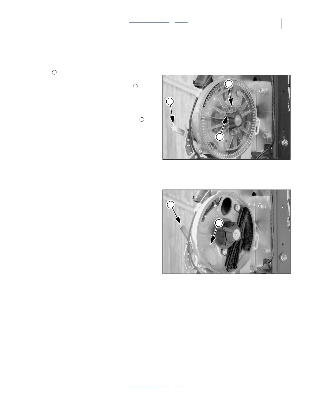
Great Plains Manufacturing, Inc. Table of Contents Index Adjustments 71
Removing a Seed Disk
Refer to Figure 94
1. Remove rain cover. If seed is present, close
shutter to prevent more seed from entering meter.
Attach funnel (page 92).
2. Hold seed disk in meter. Rotate disk clamp
counterclockwise 45° to release disk.
3. Tilting top of disk toward meter, slowly remove disk,
allowing seed to collect in funnel. Open shutter to
release remaining seed up to wing tube.
4. Clean seed from all brushes. Clean disk seat ( in
Figure 91 page 70), so that new disks can seat fully.
Inspect brushes for excess wear and damage. See
“Meter Brush Maintenance” on page 94.
5. Inspect removed disks for excess wear and damage.
Set aside any disks requiring replacement. Clean
other removed disks and place in storage. See
“Seed Disk Maintenance” on page 96.
6. Re-install the rain cover (page 68).
4
1
3
4
2
1
Figure 94
Remove Disk
29611
Row Unit Shut-Off
Skip-row operations, such as planting from every other
row when switching from 30 inch twin-row to 30 inch
single-row, requires shutting down unused rows.
Shutting off seeding at a row involves 4 to 7 steps:
1. Identify the rows to shut off.
2. Fully close seed inlet shutter (always done).
3. Replace seed disk with blank disk (always done).
4. Close seed flow to row at Y-tube (if present).
5. Lock up row unit to reduce wear (optional).
6. Reset marker extension (if used, page 150).
7. Reset monitor active row pattern and row spacing to
avoid nuisance alarms (always done).
Note: Meter drive is not disabled on 25AP row units
during shut-off.
2
1
Figure 95
Seed Inlet Shutter Closed
29609
2013-08-13 Table of Contents Index 401-625M
Page 76
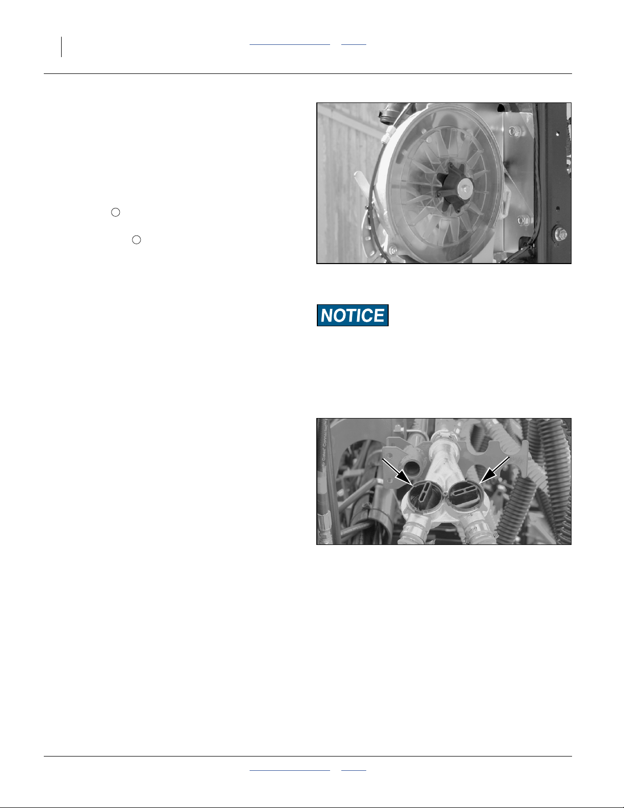
72 YP1125A & YP1625A Table of Contents Index Great Plains Manufacturing, Inc.
1. Identify Rows to Shut Off
On twin-row planters, openers are installed with short
and long opener mounts. If locking up unused rows of a
twin-row planter, shut off the front (short mount) rows.
On single-row planters with mid-length mounts, any rows
may be locked up.
2. Close Seed Shutter
Refer to Figure 95 on page 71
Lift the handle away from the plate. Move it to the top
2
position, and release the handle into the notch.
Closing the shutter prevents meter pressurization air
1
from leaking into the bulk seed air system, resulting in
lower pressures in adjacent rows, with risk of skips.
The shutter also stops seed flow from a row as soon as
the meter is empty. Bulk seed flow to the row falls to nil
Figure 96
Shutter Closed, Blank Disk Installed
29610
as soon as the seed backs up to the air release vent at
the top of the meter. If the row is served by a Y-tube, the
Y-tube also needs to be shut off for the row (step 4).
3. Install Blank Disk
Refer to Figure 96
Clean out meter. See “Meter Clean-Out” on page 92.
Irregular Seeding Risk:
Always use a blank disk in a shut-off row. Operating with no
disk, or with a seed disk but no seed, destabilizes the regulated
airflow, particularly at rows with pressure sensor lines.
Remove seed disk and install blank disk. See “Air-Pro®
Meter Disk Installation” on page 70.
Blank disks (part number 817-841C) are essential in row
shut-off, both to maintain consistent meter back-pressure
to meter pressurization and to prevent wear on a seed
disk.
Blank disks are engineered to simulate a seed disk with
seed in all pockets. Blanks are particularly important on
the rows with lines to the pressure chamber.
4. Close Y-Tubes
Refer to Figure 97
If any shut-off rows are served by a Y-tube, close the
valve for the branch to that row. Rotate the valve cap until
the indicator/handle is perpendicular to the tubes.
Closing the Y-tube prevents seed from entering an
Figure 97
Y-Tube Open and Closed
29758
unused hose, reducing waste and simplifying clean-out.
401-625M Table of Contents Index 2013-08-13
Page 77

Great Plains Manufacturing, Inc. Table of Contents Index Adjustments 73
5. Lock-Up Row
Machine Damage Hazard:
Do not lock up the rear rows on a twin-row YP1225A or
YP1625A planter. They will strike other machine components
in folding, and be damaged.
Alternate twin-row units (the front units) can be pinned in
the up position to accommodate single-row spacing.
Refer to Figure 98
The lock-up pins for each front row unit are located in
a storage hole in the row unit mount. To lock up a unit,
1
2
the unit must be raised, and the pin moved to the lock-up
3
hole in the row unit shank.
Note: If you lose a pin, the replacement part number is
805-033C
1. Raise the planter. Although this adjustment can be
made with the planter lowered, the springs will be in
tension, and will require more effort. The extra force
may also damage tools.
2. Install lift assist cylinder locks. Lower parking stands.
3. Set the down pressure spring cam to zero, per the
instructions on page 61.
4. Raise the row unit high enough that the hole for the
pin is above the lower parallel arm. This can be done
in several ways, including:
a. use a hoist at the rear of the shank
b. use a jack under the shank extension
4
5
1
2
4
3
5
Figure 98
25AP Row Unit Lock-Up Pin
Crushing and Sharp Object Hazards:
Do not attempt to lift a row unit by hand. The weight of the
unit, plus the force of the springs (even at minimum) is too
great (plus, a free hand is needed for pin insertion). Even with
multiple people lifting, hand-lifting is unsafe - there are
numerous sharp edges, and the row unit snaps down violently
if a grip is lost.
25269
29600
Crushing Hazard:
3
Use a jack or hoist. Raising a row unit on a block by lowering
the planter is risky. The potential for hydraulic failure creates
a safety hazard. Full lowering can damage components.
Refer to Figure 99
5. Remove the pin from the storage hole and insert
and secure it in the lock-up hole .
2
3
6. Lower row unit until lock-up pin rests on lower
parallel arm.
Certain Machine Damage:
Do not pin the row unit while it is in the lowered position.
If the pin is inserted below the parallel arm, unit damage
Figure 99
25AP Row Unit Locked Up
29756
occurs as soon as planting begins.
2013-08-13 Table of Contents Index 401-625M
Page 78

74 YP1125A & YP1625A Table of Contents Index Great Plains Manufacturing, Inc.
Seed Firmer Adjustments
25 Series row units accept one of two optional firmers.
Sharp Objects Hazard:
Row unit disc blades may be sharp. Use caution when making
adjustments. To adjust the Keeton® Firmer, lower the planter
until the discs of the row units are resting on the ground.
Keeton® Seed Firmer Adjustment
The optional Keeton® Seed Firmer is an engineered
polymer shape that slides down the seed trench. It traps
seeds as they exit the seed tube and firms them into the
bottom of the furrow.
Refer to Figure 100
The Firmer is provided with a preset tension which is
recommended for using the first year. The tension
screw can be tightened in subsequent years
1
according to your needs. Firmers should provide just
enough tension to push seeds to the bottom of the
trench.
Measure the distance from the ground to the head of the
tension screw. This distance should be 4 to 41⁄2inches
(10.2 to 11.4cm). If not, loosen the bolts in the mounting
bracket and select different holes until the proper
measurement is attained.
Figure 100
Keeton® Seed Firmer
1
20327
401-625M Table of Contents Index 2013-08-13
Page 79

Great Plains Manufacturing, Inc. Table of Contents Index Adjustments 75
Seed-Lok® Seed Firmer Lock-Up
Optional Seed-Lok® firming wheels provide additional
seed-to-soil contact. The wheels are spring loaded and
6
do not require adjusting. In some wet and sticky conditions the wheels may accumulate soil. To avoid problems
associated with this, you can lock-up the firmers.
Refer to Figure 101 (which depicts a row unit with discs, side
depth wheels/arms and press wheels removed for illustrative
1
purposes - removal is not necessary for lock/unlock)
To lock up Seed-Lok® wheels:
1. Raise planter. Insert lift assist cylinder locks.
2. Lift Seed-Lok®lock-up handle until lever stop is
1 2
2
3
free to rotate.
3. Rotate lever stop to side/idle position . Release
lock-up handle .
4. Push up on Seed-Lok® wheel until wheel arm
latches up .
1
4
5
To release a locked-up Seed-Lok®:
1. Insert a1⁄4in tool drive tip in the tool hole of the
handle . Alternatively, lift up on the wheel .
1 4
2. Rotate the handle clockwise (handle arm up) until
the Seed-Lok® wheel releases at the latch point
and falls free.
3. While holding the handle up, rotate the raised portion
of the lever stop under both sides of the handle
2 2
3
4
5
6
Figure 101
5
Seed-Lok® Lock-Up
Note: Engage the lever stop under the handle when
Seed-Lok®is in use. If left disengaged , a furrow
obstruction could cause unintended lock-up.
31543
2
3
at the arm end. Remove the tool.
Seed-Lok® Seed Firmer Lock-Up (older style)
Optional Seed-Lok® firming wheels provide additional
seed-to-soil contact. The wheels are spring loaded and
1
do not require adjusting. In some wet and sticky
conditions the wheels may accumulate soil. To avoid
problems associated with this, you can lock-up the
firmers.
Refer to Figure 102
To lock up Seed-Lock wheels:
1. Raise planter. Insert lift assist cylinder locks.
2. Rotate Seed-Lok® lock-up handle 90 degrees
1
down on top of row unit body.
3. Push up on Seed-Lok® wheel until wheel arm
latches up.
2
2
Figure 102
22909
Seed-Lok® Lock-Up
2013-08-13 Table of Contents Index 401-625M
Page 80
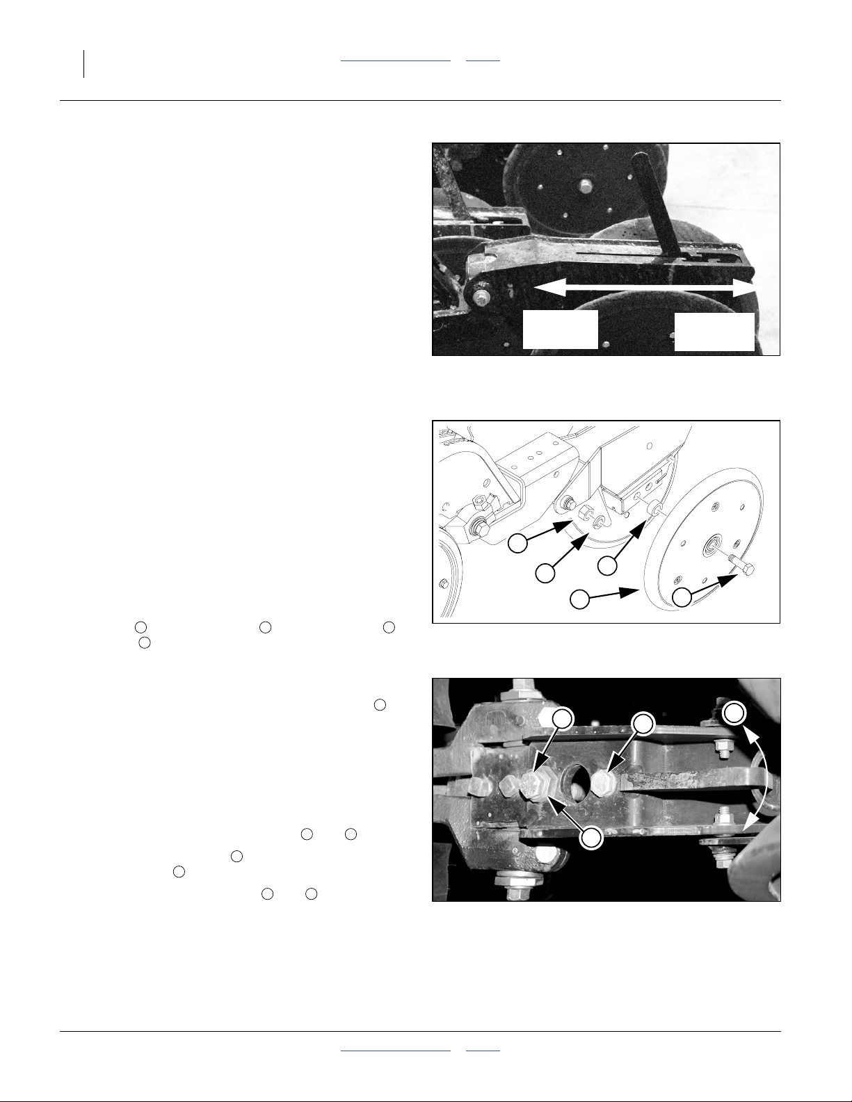
76 YP1125A & YP1625A Table of Contents Index Great Plains Manufacturing, Inc.
Press Wheel Adjustments
Attached to the rear of each row-unit is one of several
press wheel options.
To provide consistent seed firming, the press wheels are
free to move downward from their normal operating
position. This system maintains pressing action even if
the row-unit arm is lifted when the discs encounter
obstructions.
Refer to Figure 103
Press wheels are attached to each row-unit body. The
press wheels close the seed trench and gently press soil
over seed.
An adjustable spring in the press wheel mechanism
creates the down pressure needed to close the seed
trench. The amount of force needed will vary with field
conditions.
To adjust, move adjustment handle.
• For less down pressure, move handle forward toward
planter.
• For more down pressure, move handle back away
from planter.
Note: Increased press wheel spring force may require
increased row-unit down force to maintain depth.
Note: The factory setting on the press wheel is staggered
to achieve optimum residue flow.
Refer to Figure 104
To adjust press wheels from staggered to even, remove
5
⁄8inch bolt , and lock washer . Reinstall spacer ,
press wheel and hardware to the other hole location.
Press Wheel Centering
If one press wheel is running in the seed trench, or the
wheels are not centered over the trench, the angle of
the press wheel assembly can be adjusted as follows:
Refer to Figure 105
1. Determine how far, and in which direction, the press
wheel assembly needs to move to center the wheels.
2. Raise planter and install lift assist cylinder locks. See
“Important Safety Information” on page 1.
3. Loosen the1⁄2inch hex-head bolts and .
4. Turn the hex head cam under the forward hex
head jam bolt , and move the required amount.
5. Tighten both hex-head bolts and .
If press wheel adjustments do not provide satisfactory
furrow closing, your conditions may require alternate
press wheels. A variety of wheel assemblies are
available. Consult your Great Plains dealer.
1 3 4
5
7
8 9
c
9
8 9
Note: Do not loosen the two forward bolts.
Less Down
Pressure
Figure 103
Press Wheel Adjustment
2
3
4
5
Figure 104
Press Wheel Stagger
9
8
c
Figure 105
Press Wheel Centering
(View from beneath opener)
More Down
Pressure
21948
1
22907
7
25277
401-625M Table of Contents Index 2013-08-13
Page 81

Great Plains Manufacturing, Inc. Table of Contents Index 77
Troubleshooting
Planting Rate Problems
When starting up with a new planter, a new crop or a
new population it is important to physically double check
what the monitor is reporting in the cab by digging seeds.
This is to verify that you are set up correctly to plant the
desired population. Do not rely solely on the population
reported by the DICKEY-john
Also during start up it is common to encounter alarms
and readouts on the DICKEY-john® console that don’t
seem to make sense. It is critical to troubleshoot these
alarms not only to make sure the planter drive is set
properly to hit the target population, but also to fix
incorrect entries in the DICKEY-john
eliminate nuisance alarms.
Before entering the troubleshooting charts to remedy a
monitor or population problem, it is helpful to use the
following flowchart to get a handle on what may be
wrong. The basis for finding what is wrong comes from
knowing exactly what the planter is actually doing in the
soil. Always dig or observe seed on the ground when
checking populations.
®
monitor.
®
monitor to
For seed monitor issues, see also the DICKEY-john
Planter/Drill Control User Manuals,
“TROUBLESHOOTING & ALARMS” section.
Suggested Furrow Check:
Plant a short distance and dig seeds, or run with the
closing wheels wired up to leave an open seed trench.
Based on seeds found, determine an average distance
between seeds. Compare the distance between seeds
to the seed spacing listed in the charts for your
population. This is listed as “inches per seed”.
®
1. Is the spacing on the
ground correct?
2. Is the reported population
1
⁄2the actual or is the
reported population too
high by a factor of 2?
3. Is the population on the
screen close to the target
population?
No: Check the ground drive transmission and range sprocket selections, or
the population settings on a hydraulic drive unit. See also “Population
Too Low” or “Population Too High” in the troubleshooting charts.
Yes: Go to step 2.
No: Go to step 3.
Yes: An incorrect row spacing value entered in the seed monitor can cause
this. Example: 15 inches instead of 30 inches. Correct the row spacing
error on the DICKEY-john® console.
The system can also be off by a large factor if incorrect range sprockets
are installed. Check seed rate charts against range and transmission
sprockets on the planter.
No: Check seed rate charts against transmission sprockets selected. See
“Population Too Low”or“Population Too High” in the troubleshooting
charts.
Yes: If slightly under, see “Population Too Low” if slightly over, see
“Population Too High”.
2013-08-13 Table of Contents Index 401-625M
Page 82

78 YP1125A & YP1625A Table of Contents Index Great Plains Manufacturing, Inc.
Seed Pool Troubleshooting
1
29743
Figure 106
Rear Cross-Section of Air-Pro® Meter in Normal and Row-Failed Conditions
Normal:
Filling
Seed pool at shutter
prevents back-flow of
meter pressurization
air, allowing seed to
flow from delivery
system, filling inlet to
top of air release
screen.
Once inlet is filled to
top of air release
screen, air flow from
the delivery system is
blocked. No further
seed arrives until
planting reduces the
backlog at the inlet.
Normal:
Filled
Delivery Blockage or
Back-flow Starvation
No seed arriving from
manifold. Air
back-flow is
1
occurring. Causes
may include:
• low fan speed
• seed hose blockage
• no seed available
Bridging:
Screen
Oversize matter in
seed has caused a
bridge at the top of the
inlet. Air back-flow
1
is occurring.
When the bridge is
released, the seed
pool will be insufficient
to prevent back-flow.
A bridge at the shutter
is blocking flow.
Causes may include:
• oversize seed
• shutter setting too
• oversize matter in
• Y-tube closed
• meter never primed
Actions: Actions: Actions: Actions: Actions:
No action required.
Continue Planting.
No action required.
Continue Planting.
1. Correct cause of
blockage.
2. Perform a
one-row seed
pool recovery
(page 79).
3. Resume planting.
1. Close shutter.
2. Disconnect hose
at meter.
3. Tap on screen
cone and inspect.
4. Check seed pool
for foreign matter.
1. If shutter was at
2. Check seed pool
3. Resume planting.
5. Perform a
one-row seed
pool recovery
(page 79).
6. Resume planting.
29743
Bridging:
Shutter
low
seed
suggested
opening, increase
one notch.
for foreign matter.
401-625M Table of Contents Index 2013-08-13
Page 83

Great Plains Manufacturing, Inc. Table of Contents Index Troubleshooting 79
Seed Pool Recovery
When a meter has been starved of seed, back-flow of air
through the open shutter reduces delivery air flow. This
causes seed delivery to be slow. If you start or resume
planting with an empty seed pool, the delivery flow may
be too low to keep the meter supplied. The steps below
quickly “prime” the meter by rebuilding the seed pool.
Refer to Figure 107 (which depicts a recovery after an
incidence of bridging at air release screen)
1. Close the shutter . This stops the air back-flow.
2. Clear the bridge or blockage that caused the
meter to run empty.
3. With the fan running, listen for seed to fall into the
inlet.
4. Wait for seed fall to taper off and stop.
5. Open the shutter to the operating setting.
6. Start or resume planting.
1
2
3
4
5
2
3
1
29744
Figure 107
Seed Pool Recovery
4
5
29744
Population Troubleshooting Charts
Population Too Low
Problem Cause Solution
Overall
Low
Population
Incorrect seed rate Check seed rate charts
Ground Drive only: Incorrect Transmission
sprockets or shafts used
Ground Drive only: Incorrect Range
sprockets or shafts used
Empty pockets on disk (skips) due to
insufficient air pressure.
Empty pockets on disk (skips) due to sticky
seed treatments not allowing seed to rapidly
fill the pockets.
Empty pockets on disk (skips) due to rough
field conditions causing seeds to fall from
the disks.
Empty pockets on disk (skips) due to seed
pool too low, and seeds are not filling every
pocket on the disk.
Empty pockets on disk (skips) due to disk
speed too high, and pockets are not filling.
Empty pockets on disk (skips) due to
singulation (4 tufted) brush too aggressive.
Empty pockets on disk (skips) due to seed
too big for pocket.
Check Transmission sprocket tooth counts and
Driver/Driven locations.
Check Range sprocket tooth counts and Driver/Driven
locations.
Increase the controlled air to the meter. See “Fan and
Meter Pressurization Adjustment” on page 51.
Increase seed lubricant.
Decrease field speed or increase the air pressure in
the meter.
Open shutter one notch.
Decrease field speed or change to a higher cell count
disc.
Check for matted, stuck together fibers. Wash, scrape
clean, or replace as needed.
Select the correct disk for the seed size.
2013-08-13 Table of Contents Index 401-625M
Page 84

80 YP1125A & YP1625A Table of Contents Index Great Plains Manufacturing, Inc.
Population Too Low
Problem Cause Solution
Overall
Low
Population
(cont.)
Low
Population,
One Wing
Seeds are not falling from disk, and get
carried past drop zone. Static electricity can
cause small, lightweight seeds to cling to the
pocket and not fall out.
Air pressure too low, false information
driving the DICKEY-john
Low fan speed: meter starvation due to
meter pressurization, leaving insufficient air
for seed delivery
Leaking meters in split row: meter starvation
due to meter pressurization leaving
insufficient air for seed delivery
Inadequate contact wheel spring pressure Check for correct spring and gap setting, page 50.
Air pressure in contact wheel incorrect Check for correct tire air pressure, page 127.
Excess field speed Plant within speed ranges recommended in seed rate
Improper gap on speed sensor. Check speed sensor on planter for1⁄16inch to1⁄8inch
Incorrect speed sensor constant Perform speed calibration per DICKEY-john® monitor
Ground Drive only:
LH and RH Range setup not matched.
Ground Drive only:
LH and RH Transmission setup not
matched.
Clutch slipping, due to contaminants in
clutch, or wear
Skipping chain from drive to wing Check chain slack.
®
software.
The graphite component of Ezee Glide Plus addresses
this issue. Increase the amount of Easy Glide Plus
and/or more thoroughly mix the lubricant into the seed.
Compare the air pressure reported on the monitor
console to the mechanical gage. If they do not match:
• Inspect the1⁄4inch sample lines from the row units
up to the sensor chamber for leaks.
• Make sure all non-planting rows have blank disks.
• Re-zero the air pressure with the fan off.
Increase fan speed.
Install blank disks and close shutters on unused rows.
charts.
(1.6 to 3.2 mm) gap from wheel. Improper gap can
cause erratic speed signal causing monitor to falsely
report improper planting rate.
manual.
Make sure LH and RH Range settings are identical,
and that sprockets are on proper DRIVING/DRIVEN
shafts.
Make sure LH and RH Transmission settings are
identical, and that sprockets are on proper
DRIVING/DRIVEN shafts.
Lock-up clutch (page 38) until it can be overhauled or
replaced
Replace worn chain.
401-625M Table of Contents Index 2013-08-13
Page 85

Great Plains Manufacturing, Inc. Table of Contents Index Troubleshooting 81
Population Too Low
Problem Cause Solution
Low
Population,
Single Row
Shutter opening too wide - interfering with
meter pressurization
Shutter opening too narrow - starving meter
of seed (low seed pool)
Y-tube partially or completely closed,
reducing bulk flow to meter or causing
bridging
Meter starvation due to bridging at shutter Re-adjust for shutter bridging (page 69).
Meter starvation due to bridging above inlet,
caused by low seed delivery air flow
Meter starvation due to bridging above inlet,
caused by high levels of seed treatment
Skips due to low meter pressurization at one
or several rows
Skips due to skipping chain Check for worn chain, worn idlers, and low chain slack
Skips due to debris in disk pockets Remove rain covers. Inspect and clean out disks.
Row has blank disk installed Replace with seeding disk.
Seed sensor obscured Clean out seed tube (see page 93).
Adjust shutter to lower setting.
Adjust shutter to higher setting.
Open Y-tube for row
If seed is treated, increase seed lubricant.
Clear bridge (page 69). Check that seed delivery
system is getting sufficient fan air, and that there are
no other obstructions upstream.
Clear bridge (page 69). Increase seed lubricant.
Check shutter setting.
Check for excess wear on seed drop brush.
Check for loose or leaking pressure hose.
(page 100).
2013-08-13 Table of Contents Index 401-625M
Page 86

82 YP1125A & YP1625A Table of Contents Index Great Plains Manufacturing, Inc.
Population Too High
Problem Cause Solution
Overall High
Population
Overall High
Population
High
Population,
One Wing
Incorrect seed rate Check seed rate charts
Ground Drive only: Incorrect
Transmission sprockets or shafts
used
Ground Drive only: Incorrect Range
sprockets or shafts used
Two seeds per pocket on the disk
(doubles), due to excess meter
pressurization
Two seeds per pocket on the disk
(doubles), due to pockets too large
for the seed
Air meter pressure too high due to
pressure sensor not zeroed properly.
Air pressure too high, false
information driving the
DICKEY-john® software.
False alarms or actual seed rate
errors due to monitor setup with
incorrect row count, spacing or
active rows
Incorrect cell count Replace seed disks with correct disks, or reset rate for
Improper gap on speed sensor. Check speed sensor on planter for1⁄16inch to1⁄8inch
Incorrect speed sensor constant Perform speed calibration per DICKEY-john® monitor
Doubles due to incorrect disk for
crop or seed size
Sticky seeds: excess seed treatment Increase seed lubricant.
Ground Drive only: LH and RH
Range setup not matched.
Ground Drive only: LH and RH
Transmission setup not matched.
Check Transmission sprocket tooth counts and Driver/Driven
locations.
Check Range sprocket tooth counts and Driver/Driven
locations.
Methodically decrease the controlled air to the meter. See
“Fan and Meter Pressurization Adjustment” on page 51.
Select a disk with smaller pockets.
Re-zero the air pressure with the fan off. Make sure the
displayed pressure reads 0.00.
Compare the air pressure reported on the monitor console to
the mechanical gage. If they do not match:
• Inspect the1⁄4inch sample lines from the row units up to
the sensor chamber for leaks.
• Make sure all non-planting rows have blank disks.
• Re-zero the air pressure with the fan off.
When troubleshooting population issues, always first rule out
seed monitor setup. Review planter configuration and
monitor setup.
current disks (if within range).
(1.6 to 3.2 mm) gap from wheel. Improper gap can cause
erratic speed signal causing monitor to falsely report
improper planting rate.
manual.
Use recommended disk for crop and seed size.
Make sure LH and RH Range settings are identical, and that
sprockets are on proper DRIVING/DRIVEN shafts.
Make sure LH and RH Transmission settings are identical,
and that sprockets are on proper DRIVING/DRIVEN shafts.
401-625M Table of Contents Index 2013-08-13
Page 87

Great Plains Manufacturing, Inc. Table of Contents Index Troubleshooting 83
Population Too High
Problem Cause Solution
High
Population,
Single Row
Excess meter pressurization causing
doubles
Worn seed-drop brush and/or strip
brushes allowing excess seed to
pass
Incorrect seed disk with higher cell
count.
Check shutter.
Replace worn brushes.
Install correct disk.
Population Related
Problem Cause Solution
Overall
Population
Alarms
Low
Population
Bands Just
After Turns
False alarms or actual rate errors
due to monitor setup with
incorrect [active] row count or
spacing
Incorrect cell count Replace seed disks with correct disks, or reset rate for current
Improper gap on speed sensor. Check speed sensor on planter for1⁄16inch to1⁄8inch
Incorrect speed sensor constant Perform speed calibration per DICKEY-john® monitor
Insufficient oil to fan - meter
pressures low - seeds falling from
disks.
When troubleshooting population issues, always first rule out
seed monitor setup. Review planter configuration and monitor
setup.
disks (if within range).
(1.6 to 3.2 mm) gap from wheel. Improper gap can cause
erratic speed signal causing monitor to falsely report improper
planting rate.
manual.
Perform end-of-pass marker and lift operations separately. If
already performing separately, reduce marker speed, and/or
list more gradually.
Mismatch
Between
Reported and
Small seeds (example milo) are
not reliably sensed in the seed
tube
Furrow
Population
Seed tube sensor is not counting
all seeds
Seeds / revolution value in the
DICKEY-john® setup does not
match the disk cell count.
Unable to
adjust air
pressure low
enough.
2013-08-13 Table of Contents Index 401-625M
Lower limit reached in
DICKEY-john® software.
Fan speed too high, vane rotated
to maximum.
Run with rain covers in place to minimize ambient light
intrusion. Use the population adjustment factor in the
DICKEY-john® monitor system to compensate for missed
seeds. For example, change the DICKEY-john® Population
Adjustment values from 100% to 130% or 140% as needed.
Remember to set this back to 100% for large seeds.
Clean the seed tube of graphite and dust buildup with long
narrow seed tube brush. Replace sensors that malfunction.
Correct the value in a setup screen or install the correct cell
count disc.
At User Level 2, reduce the controlled air lower limit in the
software.
Reduce the fan speed.
Page 88

84 YP1125A & YP1625A Table of Contents Index Great Plains Manufacturing, Inc.
Population Related
Problem Cause Solution
Seed too
Bottom of seed tube damaged. Replace seed tube. Avoid setting planter straight down. Use
shallow or
scattered on
ground from a
Row not penetrating in tire tracks. Increase down force on parallel arm springs.
Opener depth too shallow. Change side depth wheel setting.
single row
Twin Rows
were timed
but became
out of time.
System is
unable to
Timing will change when a
population change has been
made.
Chain has jumped. Check sprockets and chain for excessive wear or rusty stuck
Signal from air pressure sensor
lost. (failed sensor or wiring)
automatically
control air
meter
pressure.
Problem Cause Solution
Single row doesn’t fill or keep up with
other rows.
Both rows on one meter outlet low or
not keeping up with other rows.
forward motion when lowering.
Re-time meters from the population based timing chart.
links.
Air pressure may be controlled manually, consult
DICKEY-john® Planter/Drill Control manual, User Level 2/3.
Seed Delivery Troubleshooting
Y tube is bent/angled off feed
pipe.
Drop tube to meter is too long,
causing seed to pool and plug
hose or Y-tube.
Blockage in air slot in top of
airbox.
Loosen pipe and spin so the bend is
straight down and Y-tube is not
pointing to front or rear of air pipe.
Shorten hose (with planter raised, but
row units lowered, to ensure hose is
not too short).
Clear by using a long skinny tool and
taking hose off through hose outlet.
It may be necessary to take top off
airbox or use side access doors to
clear junk from slot.
Bad hose routing between
delivery hose and airbox on wing.
Multiple rows fail for lack of seed. Fan speed too high/too low. Check/adjust fan speed.
Out of seed. Add seed.
Single or multiple hoses plugging just
ahead of airbox.
All rows fail. Lack of seed. Fan speed too high. Adjust fan speed.
401-625M Table of Contents Index 2013-08-13
Fan speed too high/too low. Check/adjust fan speed.
Possible air leak. Check for air leak downstream
Correct hose routing.
between box and top of meter.
Extremely high populations may
require slightly reduced field speed.
Page 89

Great Plains Manufacturing, Inc. Table of Contents Index Troubleshooting 85
Seed Delivery Troubleshooting
Problem Cause Solution
1, 2, 3, or more outlets fail.
Outlets can be side-by-side or random.
Plugging may also move from one
outlet to another.
Little or no seed to a lot of rows with
heavily treated seed.
Foreign matter in seed chamber in
bottom of airbox.
Seed treatment sticky. Add Ezee Glide Plus to seed to dry out
Treatment mixed unevenly and
plugging outlets.
Clean out seed chamber.
seed treatment.
Clean out seed. Re-mix.
General Troubleshooting
Problem Cause Solution
Population
Alarms
Excess Seed
Remaining
Seed
Consumptio
n Too High
Rows Not
Planted
See “Population Troubleshooting Charts” on page 79.
See “Population Troubleshooting Charts” on page 79.
Field size different. After ruling out population problems, re-check geography.
Excessive gaps between planter
passes.
See “Population Troubleshooting Charts” on page 79.
Field size different. After ruling out population problems, re-check geography.
Excessive overlap.
Irregular shaped field.
If not detected by seed monitor,
check for plugged row-unit seed tube
Adjust marker, page 56.
Adjust marker, page 56.
Lift planter, expose bottom of seed tube and clean out.
Uneven
seed
spacing
Planter does
not fold or
See “Population Troubleshooting Charts” on page 79.
Excessive field speed. Reduce field speed.
Unclean seed. Use clean seed.
Damaged seed tube Inspect; repair or replace.
Seed-Lok® plugging. Lock up Seed-Lok®, page 74.
Row-unit discs not turning. See “Row-unit discs not turning freely.” in this
Troubleshooting chart.
Plugged row-unit seed tube. Lift up planter, expose bottom of seed tube and clean out.
Worn/rusted sprockets and/or chain
idler or bearings.
Lack of proper seed lubrication on
seed.
Fold cylinders out of phase Re-phase cylinders, refer to page 27
Air in lines Bleed fold circuit, refer to page 97
Check and replace any worn/rusted sprockets or chain idlers.
See “Seed Lubricant” on page 111.
unfold fully
2013-08-13 Table of Contents Index 401-625M
Page 90

86 YP1125A & YP1625A Table of Contents Index Great Plains Manufacturing, Inc.
General Troubleshooting
Problem Cause Solution
Uneven
seed depth
Press wheel
or row-units
plugging
Row-unit
discs not
turning
freely.
Press
wheels not
compacting
the soil as
desired.
Excessive field speed. Reduce field speed.
Planting conditions too wet. Wait until drier weather.
Incorrect coulter depth setting. See coulter manual or set unit mounted coulter.
Excessive or improper row unit down
pressure spring setting.
Damaged seed tubes. Check seed tubes for damage.
Seed-Lok® building up with dirt. Lock up Seed-Lok®, page 74.
Row-unit not penetrating low spots. Adjust row-unit, see instructions beginning on page 60.
Rough planting conditions. Rework the field.
Seed firmer not in place and set to
correct tension.
Planting conditions too wet. Wait until drier weather.
Too much pressure on row-units. Reduce down pressure on row-units.
Coulters set too deep, bring up
excess dirt and moisture.
Planter not set to run level from front
to rear.
Backed up with planter in the
ground.
Failed disc bearings. Replace disc bearings.
Disc blades worn. Replace disc blades.
Scraper worn or damaged. Side
depth wheels not set correctly.
Row-unit plugged with dirt. Clean row-unit.
Planting conditions too wet. Wait until drier weather.
Incorrect side depth wheel
adjustment
Seed-Lok® is plugging row-unit. Lock up Seed-Lok®, page 74.
Failed disc bearings. Replace disc bearings.
Bent or twisted row-unit frame. Replace row-unit frame.
Partially plugged row-unit seed tube. Lift up planter, expose bottom of seed tube and clean out.
Incorrect spring handle setting See “Press Wheel Adjustments” on page 76.
Insufficient row unit down-force See “Row-Unit Down Pressure” on page 61.
Use of incorrectly shaped tire for
your conditions.
Not level front to rear. Check tongue height.
See 25 series row-units, page 60.
See “Seed Firmer Adjustments” on page 74.
Check coulter adjustment.
Check tongue height page 17
Clean out and check for damage.
Adjust side depth wheels page.
See “Side Gauge Wheel Adjustments” on page 66.
Wedge shaped wheels work best on narrow spacings and in
wet conditions. Round edge wheels work best in wider row
spacings and drier conditions.
401-625M Table of Contents Index 2013-08-13
Page 91

Great Plains Manufacturing, Inc. Table of Contents Index Troubleshooting 87
General Troubleshooting
Problem Cause Solution
Seed
blowing out
of bulk box
door area
Air lines
plugging
between air
box and Y
splitters
Air lines
plugging
between
Y-tube and
meter
Hydraulic
marker
functioning
improperly,
or not at all
Marker disk
does not
mark
Fan too fast. Slow down fan. If already at 3000 rpm, reset fan to 3800 rpm
and use fan butterfly valve to reduce airflow.
Seal from airbox to hopper damaged
or not adjusted.
Fan too slow. Speed up fan.
Air leaks between air box manifold
and splitters
Improper hose routing, sags or kinks With planter unfolded, hoses should for a gentle “S” shape
Sag or kink in air hose. Check air tube placement in tube mount weldment. If correct,
Meter is shut off but Y-tube is open. Shut off Y-tube.
Air tube assembly not positioned on
correct tab.
Sag in air hose due to incorrect
frame height
Marker/Fold switch set to Fold. CFM Switch must be set to “Marker”. Set tractor remote
Marker/Aux valve set to Aux On a planter with optional Auxiliary Hydraulics, selector valve
Air or oil leaks in hose fittings or
connections.
Low tractor hydraulic oil level. Check tractor hydraulic oil level.
Loose or missing bolts or fasteners. Check all bolts and fasteners.
Needle valve plugged. Open needle valve, cycle markers slowly and reset needle
Needle valve(s) in sequence valve
plugged.
Marker folding linkage does not have
enough slack to allow marker disk to
drop into field depressions.
Inspect and adjust seal. Seal should be intact, and compress
to about
Check for leaks and correct as needed.
through the holders, with no deep sags.
shorten any hose that has stretched due to age.
Move assembly to properly position Y-tubes over row meters.
Raise or lower the tongue so center portion of frame is level
with gauge wheel area.
circuit to Neutral or Float before operating switch.
must be set to Marker for markers to function. Set tractor
remote circuit to Neutral or Float before changing valve.
Check all hose fittings and connections for air or oil leaks.
valve, refer to page 56.
Open needle valves, cycle markers slowly and reset needle
valves, refer to page 56.
Maximum down float should be limited by the slot at the rod
end of the marker cylinder, refer to page 56.
Reverse marker disk to pull or throw dirt.
1
⁄2in (13mm) under seed container.
Auxiliary
Hydraulics
Inoperative
2013-08-13 Table of Contents Index 401-625M
Marker/Fold switch set to Fold CFM Switch must be set to “Marker” for Aux to function. Set
tractor remote circuit to Neutral or Float before switching.
Marker/Aux valve set to Marker Selector valve must be set to Aux. Set tractor remote circuit
to Neutral or Float before changing valve.
Page 92
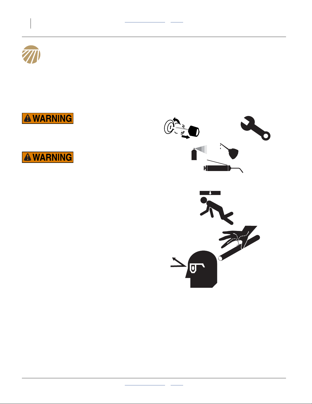
88 YP1125A & YP1625A Table of Contents Index Great Plains Manufacturing, Inc.
Maintenance and Lubrication
Maintenance
Proper servicing and maintenance is the key to long
implement life. With careful and systematic inspection,
you can avoid costly maintenance, downtime, and repair.
Always turn off and remove the tractor key before making
any adjustments or performing any maintenance.
OFF
Crushing Hazard:
Always have transport locks in place and frame sufficiently
blocked up when working on implement. You may be severely
injured or killed by being crushed under the falling implement.
High Pressure Fluid Hazard:
Check all hydraulic lines and fittings before applying pressure.
Escaping fluid under pressure can have sufficient pressure to
penetrate the skin. Fluid escaping from a very small hole can
be almost invisible. Use paper or cardboard, not body parts,
and wear heavy gloves to check for suspected leaks. If an
accident occurs, seek immediate medical attention from a
physician familiar with this type of injury.
1. After using your planter for several hours, check all
bolts to be sure they are tight.
2. Remove excess slack from chains. Clean and use
chain lube on all roller chains as needed.
3. Maintain proper air pressure in planter tires.
4. Keep disc scrapers properly adjusted.
5. Clean planter on a regular basis. Regular and
thorough cleaning will lengthen equipment life and
reduce maintenance and repair.
6. Lubricate areas listed under “Lubrication” on
page 104.
7. Replace any worn, damaged, or illegible safety
labels by obtaining new labels from your Great
Plains dealer.
401-625M Table of Contents Index 2013-08-13
Page 93

Great Plains Manufacturing, Inc. Table of Contents Index Maintenance and Lubrication 89
Tongue Lift Cylinder Locks
Center lock channels are provided for use during service
procedures with the planter partially or completely
unfolded.
They are not necessary for normal transport operation.
When the planter is fully folded, the center section is
supported at lift by the wing locks on the tongue.
Install Center Lift Locks
Refer to Figure 108
1. Remove lock channels from storage locations.
2. Raise the unfolded planter.
3. Install lock channels on exposed cylinder rods.
Remove Center Lift Locks
Refer to Figure 109
1. Raise the unfolded planter, to allow removal of the
lock channels.
2. Move the lock channels to their storage locations.
Figure 108
Lift Cylinder Lock Storage
29736
Figure 109
Frame Lift Locks Installed
29738
2013-08-13 Table of Contents Index 401-625M
Page 94
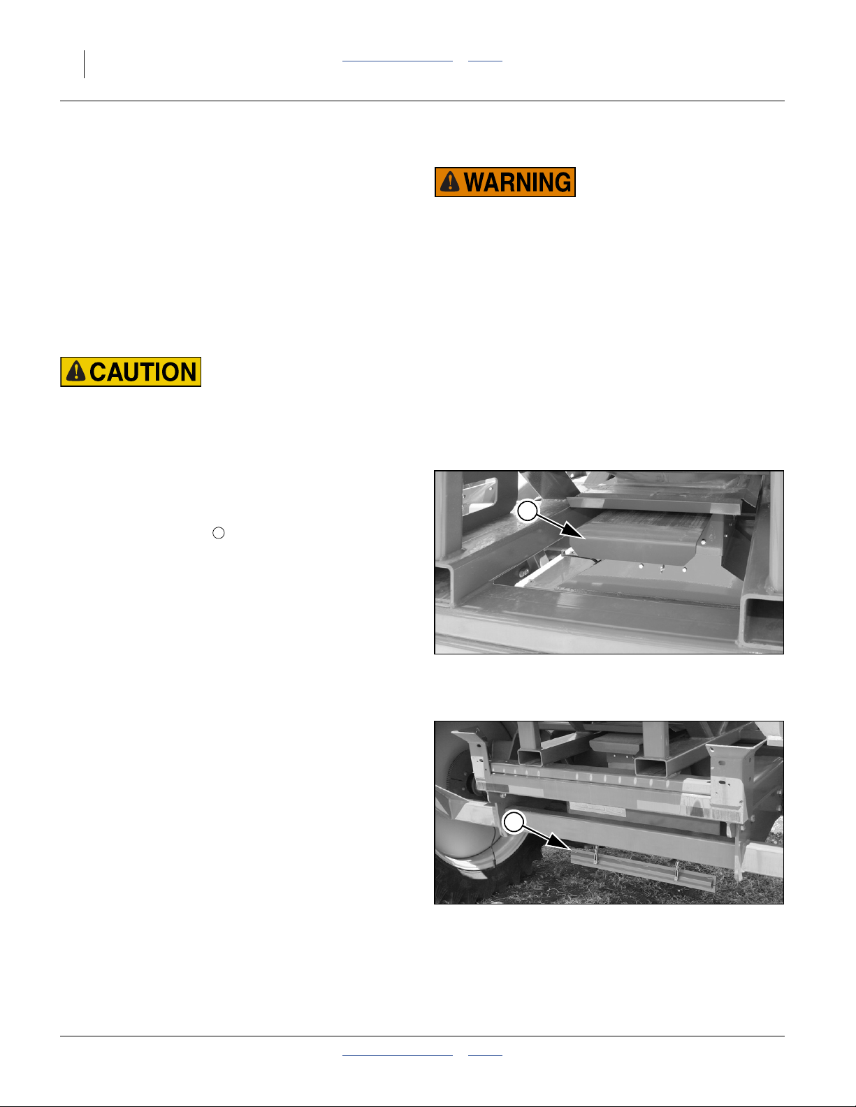
90 YP1125A & YP1625A Table of Contents Index Great Plains Manufacturing, Inc.
r
f
l
Material Clean-Out
When planting is completed, it is commonly the case that
some seed remains. There may be seed in the hopper or
bulk box, seed in the airbox, a small amount of seed in
the hose lines, and seed in the meters. Some meters
may be filled up to the air release vent (which prevents
additional seed from reaching that meter).
A complete system clean-out is a 3 step process.
1. Empty airbox (and hopper, if desired).
2. Blow residual seed to meters.
3. Clean out meters with fan running.
Possible Dust and Chemical Fume Hazard:
Wear a respirator, and any other protective equipment specified by the seed and/or seed treatment supplier. Expect dust
and fumes during hopper clean-out.
Entrapment and Rapid Suffocation Hazard:
Never enter a hopper for any reason.
Keep strainer in place at all times.
▲ A hopper that is full or merely appears full can be an
entrapment hazard. You can sink entirely into the grain, o
into an oxygen-deficient void, and suffocate in a matter o
seconds. Grain bridges and crusts are especially dangerous.
▲ When hazardous fumes are present, you can be quickly
overcome even with the hopper lid open.
▲ Do not enter a hopper for material loading, materia
unloading, hopper cleaning or meter maintenance.
▲ Clean hopper by power washing from outside hopper top.
Hopper Clean-Out
Perform hopper clean-out with the fan off.
Refer to Figure 110
1. Close the slide gate at the base of the hopper.
2. Place a tarp under the seed cart.
Refer to Figure 111
3. Open the clean-out door on the bottom of the airbox.
Seed in the airbox immediately falls onto the tarp.
Note: If needed, additional access doors are provided.
4. Open the slide gate slowly. The remaining seed in
the hopper falls onto the tarp. Use the slide gate to
regulate the flow and, as needed, stop it while
recovering seed from the tarp.
5. Rapidly open and close the slide gate to dislodge
seed in the tracks. Tap on the sides of the hopper to
dislodge residual seed.
6. Close slide gate.
Close clean-out door.
7. Perform an air system clean-out to remove final
amounts of residual seed from airbox, and all seed in
meters.
1
1
Figure 110
Hopper Slide Gate Open
2
29495
401-625M Table of Contents Index 2013-08-13
Airbox Clean-Out Door Open
Figure 111
29494
Page 95

Great Plains Manufacturing, Inc. Table of Contents Index Maintenance and Lubrication 91
Air System Clean-Out
Refer to Figure 112
1. Shut off slide gate door at bottom of seed box or bulk
hopper.
2. Place a pan or tarp under the airbox manifold to
catch seed.
Refer to Figure 113
3. If the planter has Y-tubes, shut off the gates at all of
the Y-tubes.
Refer to Figure 114
4. Open airbox clean-out door to empty seed from the
manifold.
Note: If needed, additional access doors are provided.
5. Shut the clean-out door under manifold.
6. Turn on the air fan and let it run. Use the
“SPLIT AIR -” softkeya to reduce the regulated air
pressure to a low value, 1 inch H2O or less - this
diverts most of the air to the bulk seed delivery
system.
3
Figure 112
Slide Gate Closed
29495
If most of the meters are shut off, reduce fan speed
as necessary to obtain a low meter pressurization.
7. Start at one end of planter and perform a meter
clean-out (page 92).
8. Open the Y-tube gate feeding that meter. Let the air
blow seed out of the meter. Use the meter shutter to
start and stop seed flow if using a small container.
9. Close the Y-tube gate and shutter for that meter.
10. Repeat procedure on the next meter in line. Continue
with this procedure until you have reached the
opposite end of the planter.
11. Final Check:
During air system clean-out, it is common for a few
seeds to dislodge and make their way to meters
already cleaned. To avoid seed size causing
problems for the next disk to be used, and to avoid
crop mixing, make a pass along all the rows, opening
and closing shutters, removing any stray seed.
Figure 113
Y-Tube Shut-Off
2
Figure 114
Airbox Clean-Out Door Open
29758
29494
a. The “FILL METER” function can divert all the air to seed delivery, but only does so for a short period of time (~90 seconds).
2013-08-13 Table of Contents Index 401-625M
Page 96

92 YP1125A & YP1625A Table of Contents Index Great Plains Manufacturing, Inc.
Meter Clean-Out
When planting is completed, it is commonly the case that
some seed remains. There may be seed in the hoppers,
hose lines, and meters.
Refer to Figure 115
The planter includes an 817-811C container for meter
clean-out, stored in a spring-loaded holder at the right
rear of the air manifold. The container can hold all the
seed in the meter and inlet (up to a closed slide gate).
The container can be converted into a true funnel for
complete system clean-out.
Note: The hoppers are connected to the rows with
clamped hose, and are not intended to be routinely
unlatched and tipped for clean-out.
Funnel Conversion
Materials and tools needed:
• a length of 11⁄2inch I.D. hose
2
• a worm drive clamp with a working diameter of
3
approximately 11⁄2 to 21⁄4inches
• a hacksawa with fine-toothed blade
Trim the sump from the funnel. Slide the hose fully
onto the funnel tip. Secure with clamp (do not
-over-tighten clamp, the funnel wall be crushed).
The choice of complete system clean-out process
depends on whether you are using the 817-811C as a
container or funnel.
4 2
1
1
3
4
3
2
Figure 115
Convert Container to Funnel
a. The funnel wall is thin ABS. Scissor-type pipe-cutting tools may fracture it. Rotary-type pipe cutting tools may slip off.
29988
401-625M Table of Contents Index 2013-08-13
Page 97

Great Plains Manufacturing, Inc. Table of Contents Index Maintenance and Lubrication 93
Refer to Figure 116
The 817-811C seed collection accessory (funnel )
provided with the planter can be used in one of two ways:
• As provided, the 817-811C is a container that can hold
the entire seed volume present from the meter up to a
Y-tube (or two where the row hose connects to the
wing tubes).
• The 817-811C can also be used as a true funnel. For
this use, cut the end off the sump , and attach a
hose or tube with 11⁄2inch (3.8 cm) inside diameter.
The funnel may be attached to the housing of the seed
meter, freeing your hands for other tasks during
clean-out. Normal use of the funnel is:
1. Close the seed inlet shutter on the meter (page 68).
This minimizes the seed volume at disk removal.
2. Remove the rain cover (page 68). The funnel cannot
be snapped in place with the cover installed.
3. Align the left (rear) end of the funnel lip with the
top of the lower (rear) cover latch ear. Place the right
(front) end of the funnel lip between the meter
housing and the seed tube.
4. Rotate the funnel forward until the slot at lip center
engages a tab on the bottom center of the meter
housing.
5. Remove the seed disk (page 71).
6. Slowly open the seed shutter (page 68) to empty the
seed up to the Y-tube or wing tube.
7. If the air system is running (and Y-tube open), there
may be more seed than the funnel can hold (as a
container). Use the shutter to turn seed flow off, and
empty funnel.
Refer to Figure 117
8. Clean seed from all brushes (shop vac
recommended).
9. Inspect brushes (page 94).
10. Rotate funnel clockwise, remove and empty.
11. For imminent operations:
Install next seed wheel or blank disk (page 72) for
operations. Set inlet shutter for next seed (page 68).
12. For storage:
Close seed inlet shutter. Leave disk out.
13. Re-install rain cover (page 68).
Seed Tube Clean-Out
The seed sensor in the seed tube can be obscured by
build-up of dust, dirt and seed treatments. This can
cause false low population alarms.
The planter incudes a seed tube brush (Great Plains part
number 891-259C).
2
4
1
3
4
2
Funnel Positioned and Engaged
Alternate Meter Clean-Out
3
To use a shop vacuum cleaner, with narrow hose nozzle,
to clean out a meter:
• Close the seed shutter.
• Release the meter clamp, hold the disk against the
meter.
• Tip the top of the disk away from the meter.
• Insert hose nozzle and remove seed.
• Open shutter to allow seeds in inlet and drop hose to
flow to vac nozzle.
5
1
Figure 116
29612
7
6
Figure 117
Brush Inspection
If the seed meter is empty, remove the seed disc and
insert the brush into the seed tube from above. With
the planter raised, you can also insert the brush from
below, whether the meter is empty or not.
4
29608
2013-08-13 Table of Contents Index 401-625M
Page 98

94 YP1125A & YP1625A Table of Contents Index Great Plains Manufacturing, Inc.
Meter Brush Maintenance
Possible Chemical Hazard:
Wear a respirator for brush cleaning. Brushes will have talc
and graphite residue, and may have residues of hazardous
seed treatments.
Refer to Figure 118
A HEPA vacuum cleaner is recommended for brush
cleaning. Washing brushes is not recommended and
may cause matting. Do not scrape them with sharp
instruments.
The first indications of excess brush or damage wear are
normally observed on the seed monitor or in air system
operation.
• If the tufted brushes are worn/damaged, the seed
“double” rate rises, increasing population.
Finding an occasional cracked seed “hung up” on a
tuft fiber is not uncommon, and is not an indicator that
brush maintenance is required. Merely remove the
seed.
• If the strip brushes are worn/damaged, air pressure
regulation may become unstable, or require increasing
fan speed over time.
5
6
5
7
6
Figure 118
Brushes
29608
If you find you need to exceed recommended fan rpm
ranges, the regulated air system may be taking too
much air due to meter leakage.
In severe cases, seed may leak past the strip brushes,
causing spikes in population. If you frequently observe
seed in between the strip brushes, one or both may
need replacement.
• If the seed drop brush is worn/damaged, its
anti-static effect may fade, which can result in “skips”
due to smaller seeds failing to release, and lower
populations.
If an obvious groove is worn in the drop brush, replace
it.
7
401-625M Table of Contents Index 2013-08-13
Page 99

Great Plains Manufacturing, Inc. Table of Contents Index Maintenance and Lubrication 95
Meter Brush Replacement
Consult the Parts manual (401-625P) for current
replacement part numbers.
Refer to Figure 119
Tufted Brush Replacement
1. Remove and save both 10-24 hex head cap
screws and nylock nuts (not shown).
2. Remove the tufted brush assembly , and replace
with new assembly.
3. Re-insert the 10-24 screws, and re-start the nylock
nuts. Carefully tighten each nut just until plate has no
play under the screw heads.
4. Add a half turn to the nuts. Do not tighten fasteners
to normal 10-24 torque, or the plate may fracture.
Strip Brush Replacement
Note: Do not loosen or remove any of the three5⁄16-18
1. Insert the flat blade of a large screwdriver into the
slots of the brush holder snaps . Turn each snap
clockwise to release brush holder .
2. Prepare to catch drop brush (which will fall lose).
Slide brush holder left and up to free front edge from
under washer . Remove brush holder.
3. Remove used strip brushes from the holder by
sliding them downward out of the grooves.
Refer to Figure 120
4. Insert replacement strip brushes into grooves at
holder bottom so that notched ends are at the
bottom.
Refer to Figure 119
5. Check strip brush positioning with a trial re-insertion
of the brush holder. The ends of the long brush must
fit snugly into meter housing grooves at top and
lower rear . The bottom end of the short brush
must fit snugly in the lower front housing groove .
If any significant force is require to re-seat the brush
holder, a strip brush is likely too high or too low.
6. Relax the position of the brush holder, re-position the
drop brush (see below), and re-seat the brush
holder.
7. Starting with the bottom snap, swing snaps back
into engagement.
11
12
cap screws retaining the brush holder.
15
13
14
16
17
18
20
19
20
13
12 15
19
13
14
16
11
17
13
20
21
Figure 119
Brush Replacement
29719
18
18
Figure 120
Strip Brush Notches
Seed Drop Brush Replacement
Refer to Figure 119
1. Insert the flat blade of a large screwdriver into the
slots of the brush holder snaps . Turn each snap
clockwise to release brush holder .
2. Prepare to catch drop brush (which will fall lose).
Slide brush holder left and up. Remove drop brush.
3. Position new drop brush so that it is flat against back
of meter housing, and under ridges on leading edge
of brush holder.
4. Slide holder forward/down to engage drop brush.
Swing lower, then upper snap into engagement.
13
14
16
29720
2013-08-13 Table of Contents Index 401-625M
Page 100
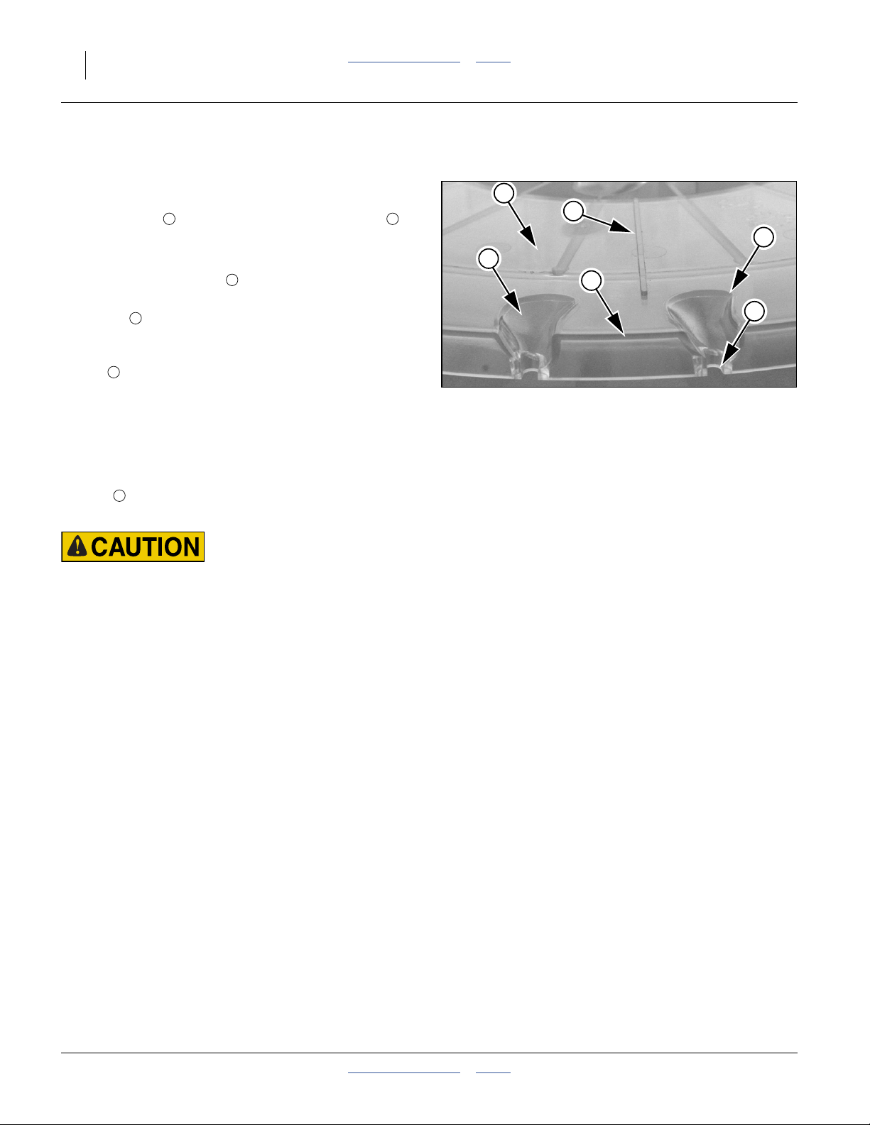
96 YP1125A & YP1625A Table of Contents Index Great Plains Manufacturing, Inc.
Seed Disk Maintenance
Refer to Figure 121
When removing seed disks, inspect them for wear and
damage. If there is any seed dust or treatment build-up in
the cell pockets , or along the raised wiper ridges ,
clean the disks and re-inspect.
Replace disks for conditions including:
• Chips at circumference . These will leak air.
• Chips at edges or in sculpted surfaces of cell
pockets . These can leak air and/or adversely affect
singulation.
• Cracks over 2 inches (5 cm) long in the working
4
face of the disk, or any cracks in support webs or to
an edge.
• Warping - if any part of the disk does not press firmly
on the seed drop brushes (page 70) in operation,
replace the disk.
• Wear - if a wiper ridge is worn away, replace the disk.
If the seed pockets are worn through, or the air
5
ports have enlarged, replace the disk.
Cleaning and Storing Seed Disks
1 2
3
1
4
2
1
1
3
5
Figure 121
Disk Seed Cells and Wiper
29613
Possible Chemical Hazard:
Wear gloves when washing disks. Avoid spray. Do not wash
disks where food is prepared, or where cookware or dinnerware is washed. Seed disks will have talc and graphite residue,
and may have residues of hazardous seed treatments. Although
the disks are dishwasher-safe, do not wash them in an appliance also used for food preparation or food serving items.
Use warm or hot water, mild soap, and a sponge or soft
brush to remove build-up.
If disks are washed, allow them to dry completely prior to
storage.
Retain original shipping cartons for disk storage.
Otherwise, store them on edge (and not leaning), or
stacked horizontally on a spindle, to eliminate any risk of
warps. Any seed residue on disks may attract pests.
Fully enclose dry disks to prevent rodent damage.
401-625M Table of Contents Index 2013-08-13
 Loading...