

Page 1

Operator’s Manual
2005+ YP1225 & YP1625
Yield-Pro® Planter
Manufacturing, Inc.
www.greatplainsmfg.com
Read the operator’s manual entirely. When you see this symbol, the subsequent
instructions and warnings are serious - follow without exception. Your life and
!
the lives of others depend on it!
27280
Cover illustration may show optional equipment not supplied with standard unit
© Copyright 2008 Printed 07/09/2009 401-226M
Page 2

Page 3

Great Plains Manufacturing, Inc.
Table of Contents
Important Safety Information .................................. 1
Introduction ............................................................ 10
Description of Unit .................................................... 10
Document Family ..................................................... 10
Intended Usage .................................................... 10
Covered Models ....................................................... 10
Using This Manual.................................................... 10
Definitions............................................................. 10
Owner Assistance .................................................... 11
Product Support ................................................... 11
Preparation and Setup ........................................... 12
Pre-Start Checklist ................................................... 12
Protecting Hydraulic Motor Seals ............................. 12
Hydraulic Hose Hookup............................................ 12
Hitching Tractor to Planter........................................ 13
3-Point Hitch......................................................... 13
Hydraulic Tongue Hitch ........................................ 13
Either Hitch........................................................... 14
Hydraulic Charge and Bleed .................................... 15
Lift Hydraulics....................................................... 15
Cylinder Hydraulics............................................... 15
Leveling Frame Side-to-Side.................................... 15
Wing Alignment ........................................................ 17
Optional Monitor Mounting Plate .............................. 18
Operating Instructions........................................... 19
Pre-Start Checklist ................................................... 19
Folding the Planter ................................................... 20
Unfolding the Planter................................................ 22
Changing the Seed Box or Hopper .......................... 23
Using Auxiliary Hydraulic Circuit........................... 24
Pre-Usage Checklist................................................. 25
Transporting ............................................................. 27
Field Operation......................................................... 28
Seed Hopper Sensor............................................ 28
Monitor Operation................................................. 29
Electric Clutch Operation.......................................... 29
Electric Clutch Lockup.......................................... 30
Marker Operation ..................................................... 31
Rephasing Lift System.......................................... 31
Rephasing Fold System ....................................... 31
Airbox Operation ...................................................... 32
Fan Operation ...................................................... 32
Y-Tubes................................................................ 32
Airbox Troubleshooting......................................... 33
Fertilizer Tanks (Option) ...........................................34
Filling Tanks ..........................................................34
Hypro Pump ..........................................................34
Parking......................................................................35
3 Point Hitch..........................................................35
Hydraulic Tongue Hitch.........................................35
Either Hitch............................................................35
Storage .....................................................................36
Adjustments ............................................................37
Planting Rate ............................................................38
Drive Speed Range Sprockets..............................38
Transmission Sprockets........................................38
Contact Wheel Drive .............................................39
Checking Singulated Planting Rate ..........................40
Seed rate charts....................................................40
Marker Adjustments ..................................................41
Dual Marker Speed Adjustment ............................41
Marker Extension ..................................................41
Marker Disk Adjustment ........................................42
Hydraulic Drive Height Switch...................................42
Setting Fertilizer Rate ...............................................43
Hypro Pump ..........................................................43
Ground Drive Pump ..............................................44
Fan Adjustments .......................................................44
Row Implement Adjustments ....................................45
Frame-Mounted Row Accessories ........................45
Terra-Tine™ Adjustment...................................45
Frame-Mounted Coulters ..................................46
Vantage I Fertilizer ............................................46
25 Series Row-Unit Adjustments ..........................47
Row-Unit Down Pressure..................................48
Row Unit Lock-Up .............................................49
Unit-Mount Cleaner Adjustments ......................50
Unit-Mounted Coulter Adjustments ...................51
Row-Unit Planting Depth...................................52
Side Gauge Wheel Adjustments .......................52
Adjusting Gauge Wheel Scrapers .....................53
Meter Exchange and Adjustments ........................54
Meter Removal..................................................54
Singulator Plus™ Meter Wheel Replacement.......56
Meter Installation...................................................58
Finger Meter Adjustments .....................................59
Finger Meter Brush Adjustment ........................59
Finger Meter Inserts ..........................................60
Seed Firmer Adjustments......................................61
© Copyright 2005, 2006, 2007, 2008. All rights Reserved.
Great Plains Manufacturing, Inc. providesthis publication “as is” without warranty of any kind, eitherexpressed or implied. While every precaution has been taken in the preparation
of this manual, Great Plains Manufacturing, Inc. assumes no responsibility for errors or omissions. Neither is any liability assumed for damages resulting from the use of the information contained herein. Great Plains Manufacturing, Inc. reserves the right to revise and improve its products as it sees fit. This publication describes the state of this product at
the time of its publication, and may not reflect the product in the future.
The following are trademarks of Great Plains Mfg., Inc.: Application Systems, Ausherman, Land Pride, Great Plains
All other brands and product names are trademarks or registered trademarks of their respective holders.
07/09/2009 401-226M
Great Plains Manufacturing, Incorporated Trademarks
Printed in the United States of America.
Page 4

YP1225 and 1625 Great Plains Manufacturing, Inc.
Keeton Seed Firmer Adjustment ....................... 61
Seed-Lok™ Seed Firmer Lock-Up .................... 61
Press Wheels........................................................62
Setting Relief Valve............................................... 63
Strainer .....................................................................63
Orifice Plate Selection........................................... 64
Orifice Size Charts ............................................ 64
Troubleshooting......................................................65
Maintenance and Lubrication ................................ 69
Maintenance .............................................................69
Bleeding Hydraulics ..................................................70
Bleeding Lift Hydraulics ........................................70
Bleeding Fold Cylinder Hydraulics ........................70
Bleeding Marker Hydraulics ..................................70
Cleaning Out Meters ................................................. 71
Precision Meter .....................................................71
Finger Pickup Meter..............................................71
Cleaning Out Air System...........................................72
Meter Drive Chain ..................................................... 72
Finger Set Installation Instructions............................73
Installation Steps................................................... 73
Annual Maintenance .............................................73
Precautions ....................................................... 73
Disk Spreaders and Scrapers ................................... 74
25 Series Row-Unit Side Wheels..........................74
Marker Maintenance .................................................75
Fertilizer System Maintenance..................................75
Liquid Fertilizer Strainer ............................................ 75
Lubrication ................................................................76
Seed Lubricants ....................................................82
Talc Lubricant....................................................82
Graphite Powder ............................................... 82
Options and Accessories.......................................83
Hydraulic Tongue......................................................83
Markers ..................................................................... 83
Fertilizer System .......................................................83
Fertilizer Manifolds................................................84
Fertilizer Orifice Plates..........................................84
Liquid Fertilizer Tank.................................................84
Ground Drive Fertilizer Pump ...................................84
Veris Hydraulic Drive ................................................85
82bu or 150 bu Seed Hopper....................................85
Seed Lubricants ....................................................85
Auxiliary Hydraulic kit................................................86
Smart Box Mounting Kit ........................................86
Row Options, Frame-Mounted..................................87
Underframe Attachment Kit................................... 87
Terra-Tines ...........................................................87
Stand-Alone Terra Tines ................................... 87
Coulter-Mounted Terra Tines ............................ 87
Frame-Mounted (Zone) Coulters...........................88
Vantage I Coulters ................................................88
Frame-Mounted Coulter Only............................88
Frame-Mounted Vantage I Coulter ...................88
Row Options (Unit-Mount) ........................................ 89
Unit-Mounted Row Cleaners................................. 89
Unit-Mounted Disk Coulters.............................. 90
Coulter Blades .................................................. 91
Gauge Wheel Scrapers ........................................ 91
Seed Meters ......................................................... 91
Seed Meter Wheels ..........................................92
Seed-Lok® Seed Firmer....................................... 92
Keeton Seed Firmer.............................................. 93
Row Unit Press Wheels ........................................ 93
Hydraulic Drive Operating Instructions................ 94
Drive Operational Requirements .............................. 94
Hydraulic System:................................................. 94
Electrical System: ................................................. 94
Tractor Hookup......................................................... 94
Hydraulics: ............................................................ 94
Electrical: .............................................................. 94
Controller Menu ........................................................ 95
Console Functions.................................................... 96
Calibration ................................................................ 96
Speed Calibration ................................................... 101
Operations .............................................................. 103
Before going to the field...................................... 103
In Field ................................................................ 104
Planting Calibration............................................. 105
Varying Rates with Pre-set Function ...................... 107
GPS-Based Planting............................................... 108
FarmWorks SiteMate .......................................... 108
SiteMate Settings: (version 8.12)........................ 108
GP Precision Population Settings....................... 109
Troubleshooting with SiteMate ........................... 109
Ag Leader PF3000.............................................. 110
PF3000 Settings: ............................................ 110
GP Precision Population Settings................... 110
Troubleshooting with PF3000 ............................. 111
Veris Maintenance.................................................. 112
To change the element: ...................................... 112
Veris Troubleshooting............................................. 113
Drive will not rotate: ............................................ 113
Drive rotates but not at desired speed:............... 114
Calibration Troubleshooting:............................... 115
Veris Troubleshooting Flow Chart .......................... 116
Veris Electronics Troubleshooting .......................... 117
Appendix ............................................................... 118
Specifications and Capacities................................. 118
Tire Inflation............................................................ 118
Torque Values Chart .............................................. 119
Hydraulic System Diagram ..................................... 120
Chain Routing......................................................... 121
Warranty ................................................................. 122
Index ...................................................................... 123
401-226M 07/09/2009
Page 5

Great Plains Manufacturing, Inc. 1
Important Safety Information
Look for Safety Symbol
The SAFETY ALERT SYMBOL indicates there is a
potential hazard to personal safety involved and extra
safety precaution must be taken. When you see this
symbol, be alert and carefully read the message that follows it. In addition to design and configuration of equipment, hazard control and accident prevention are
dependent upon the awareness, concern, prudence and
proper training of personnel involved in the operation,
transport, maintenance and storage of equipment.
Be Aware of Signal Words
Signal words designate a degree or level of hazard seriousness.
DANGER indicates an imminently hazardous situation
which, if not avoided, will result in death or serious injury.
This signal word is limited to the most extreme situations,
typically for machine components that, for functional purposes, cannot be guarded.
WARNING indicates a potentially hazardous situation
which, if not avoided, could result in death or serious
injury, and includes hazards that are exposed when
guards are removed. It may also be used to alert against
unsafe practices.
CAUTION indicates a potentially hazardous situation
which, if not avoided, may result in minor or moderate
injury. It may also be used to alert against unsafe practices.
!
!
!
!
DANGER
WARNING
CAUTION
Be Familiar with Safety Decals
▲ Read and understand “Safety Decals” on page 6, thor-
oughly.
▲ Read all instructions noted on the decals.
▲ Keep decals clean. Replace damaged, faded and illegible
decals.
Prepare for Emergencies
▲ Be prepared if a fire starts
▲ Keep a first aid kit and fire extinguisher handy.
▲ Keep emergency numbers for doctor, ambulance, hospital
and fire department near phone.
07/09/2009 401-226M
911
Page 6
2 YP1225 and 1625 Great Plains Manufacturing, Inc.
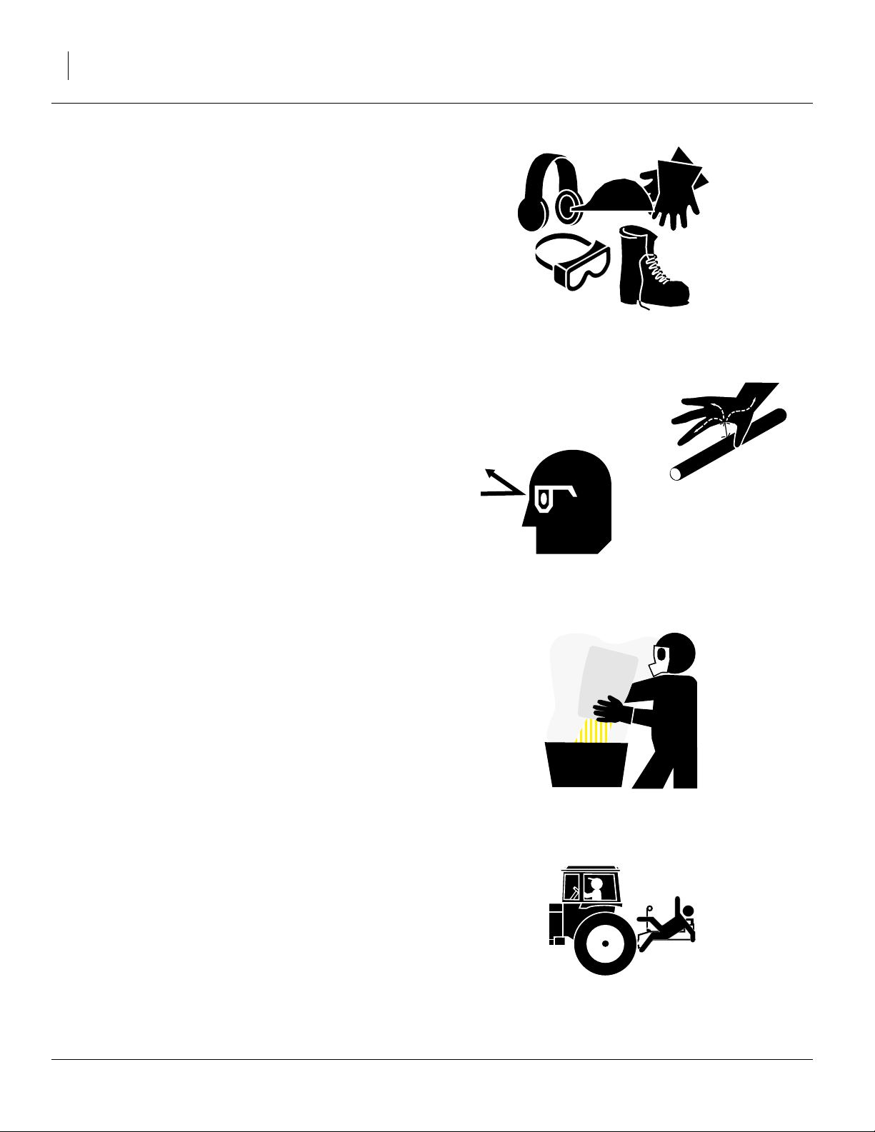
Wear Protective Equipment
▲ Wear protective clothing and equipment.
▲ Wear clothing and equipment appropriate for the job. Avoid
loose-fitting clothing.
▲ Because prolonged exposure to loud noise can cause hear-
ing impairment or hearing loss, wear suitable hearing protection such as earmuffs or earplugs.
▲ Because operating equipment safely requires your full
attention, avoid wearing entertainment headphones while
operating machinery.
Avoid High Pressure Fluids
Escaping fluid under pressure can penetrate the skin,
causing serious injury.
▲ Avoid the hazard by relieving pressure before disconnecting
hydraulic lines.
▲ Use a piece of paper or cardboard, NOT BODY PARTS, to
check for suspected leaks.
▲ Wear protective gloves and safety glasses or goggles when
working with hydraulic systems.
▲ If an accident occurs, seek immediate medical assistance
from a physician familiar with this type of injury.
Handle Chemicals Properly
Agricultural chemicals can be dangerous. Improper use
can seriously injure persons, animals, plants, soil and
property.
▲ Read and follow chemical manufacturer’s instructions.
▲ Wear protective clothing.
▲ Handle all chemicals with care.
▲ Avoid inhaling smoke from any type of chemical fire.
▲ Store or dispose of unused chemicals as specified by chemi-
cal manufacturer.
Keep Riders Off Machinery
Riders obstruct the operator’s view. Riders could be
struck by foreign objects or thrown from the machine.
▲ Never allow children to operate equipment.
▲ Keep all bystanders away from machine during operation.
401-226M 07/09/2009
Page 7
Great Plains Manufacturing, Inc. 3
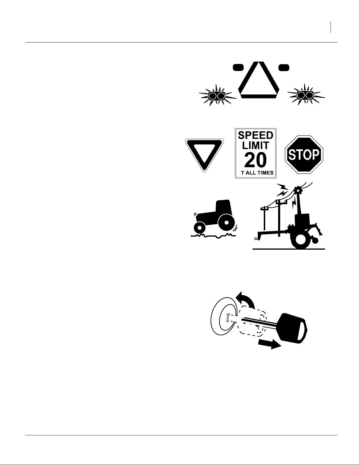
Use Safety Lights and Devices
Slow-moving tractors and towed implements can create
a hazard when driven on public roads. They are difficult
to see, especially at night.
▲ Use flashing warning lights and turn signals whenever driv-
ing on public roads.
Use lights and devices provided with implement
Transport Machinery Safely
Maximum transport speed for implement is 20 mph (32
kph). Some rough terrains require a slower speed. Sudden braking can cause a towed load to swerve and
upset.
▲ Do not exceed 20 mph (32 kph). Never travel at a speed
which does not allow adequate control of steering and stopping. Reduce speed if towed load is not equipped with
brakes.
A
▲ Comply with state and local laws.
▲ Do not tow an implement that, when fully loaded, weighs
more than 1.5 times the weight of towing vehicle.
▲ Carry reflectors or flags to mark planter in case of break-
down on the road.
▲ Keep clear of overhead power lines and other obstructions
when transporting. Refer to transport dimensions under
“Specifications and Capacities” on page 118.
▲ Do not fold or unfold the planter while the tractor is mov-
ing.
Shutdown and Storage
▲ Lower planter, put tractor in park, turn off engine, and
remove the key.
▲ Secure planter using blocks and supports provided.
▲ Detach and store planter in an area where children nor-
mally do not play.
OFF
07/09/2009 401-226M
Page 8
4 YP1225 and 1625 Great Plains Manufacturing, Inc.
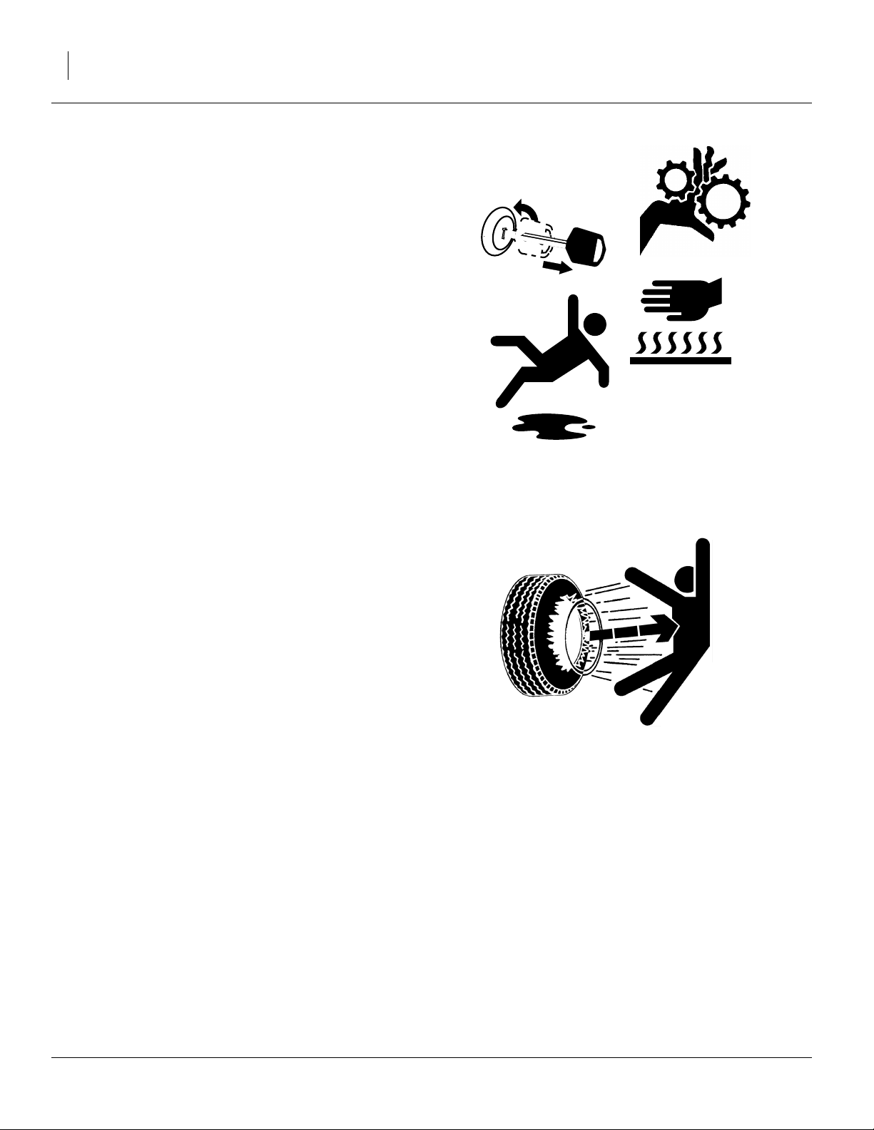
Practice Safe Maintenance
▲ Understand procedure before doing work. Use proper tools
and equipment. Refer to this manual for additional information.
▲ Work in a clean, dry area.
▲ Lower the planter, put tractor in park, turn off engine, and
remove key before performing maintenance.
▲ Make sure all moving parts have stopped and all system
pressure is relieved.
▲ Allow planter to cool completely.
▲ Disconnect battery ground cable (-) before servicing or
adjusting electrical systems or before welding on planter.
▲ Inspect all parts. Make sure parts are in good condition and
installed properly.
▲ Remove buildup of grease, oil or debris.
OFF
▲ Remove all tools and unused parts from planter before
operation.
Tire Safety
Tire changing can be dangerous and should be performed by trained personnel using correct tools and
equipment.
▲ When inflating tires, use a clip-on chuck and extension hose
long enough for you to stand to one side–not in front of or
over tire assembly. Use a safety cage if available.
▲ When removing and installing wheels, use wheel-handling
equipment adequate for weight involved.
401-226M 07/09/2009
Page 9
Great Plains Manufacturing, Inc. 5
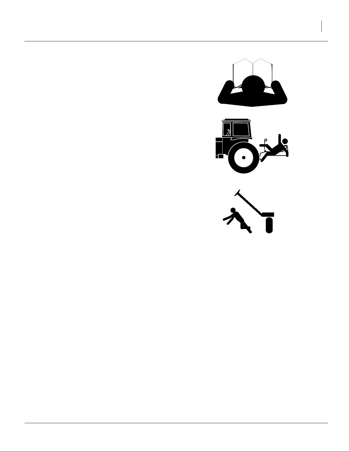
Safety At All Times
Thoroughly read and understand the instructions in this
manual before operation. Read all instructions noted on
the safety decals.
▲ Be familiar with all planter functions.
▲ Operate machinery from the driver’s seat only.
▲ Do not leave planter unattended with tractor engine run-
ning.
▲ Do not dismount a moving tractor. Dismounting a moving
tractor could cause serious injury or death.
▲ Do not stand between the tractor and planter during hitch-
ing.
▲ Keep hands, feet and clothing away from power-driven
parts.
▲ Wear snug-fitting clothing to avoid entanglement with mov-
ing parts.
▲ Watch out for wires, trees, etc., when folding and raising
planter. Make sure all persons are clear of working area.
07/09/2009 401-226M
Page 10
6 YP1225 and 1625 Great Plains Manufacturing, Inc.
Safety Decals
Safety Reflectors and Decals
Your implement comes equipped with all lights, safety
reflectors and decals in place. They were designed to
help you safely operate your implement.
▲ Read and follow decal directions.
▲ Keep lights in operating condition.
▲ Keep all safety decals clean and legible.
▲ Replace all damaged or missing decals. Order new decals
from your Great Plains dealer. Refer to this section for
proper decal placement.
▲ When ordering new parts or components, also request cor-
responding safety decals.
818-055C
To install new decals:
1. Clean the area on which the decal is to be placed.
2. Peel backing from decal. Press firmly on surface,
being careful not to cause air bubbles under decal.
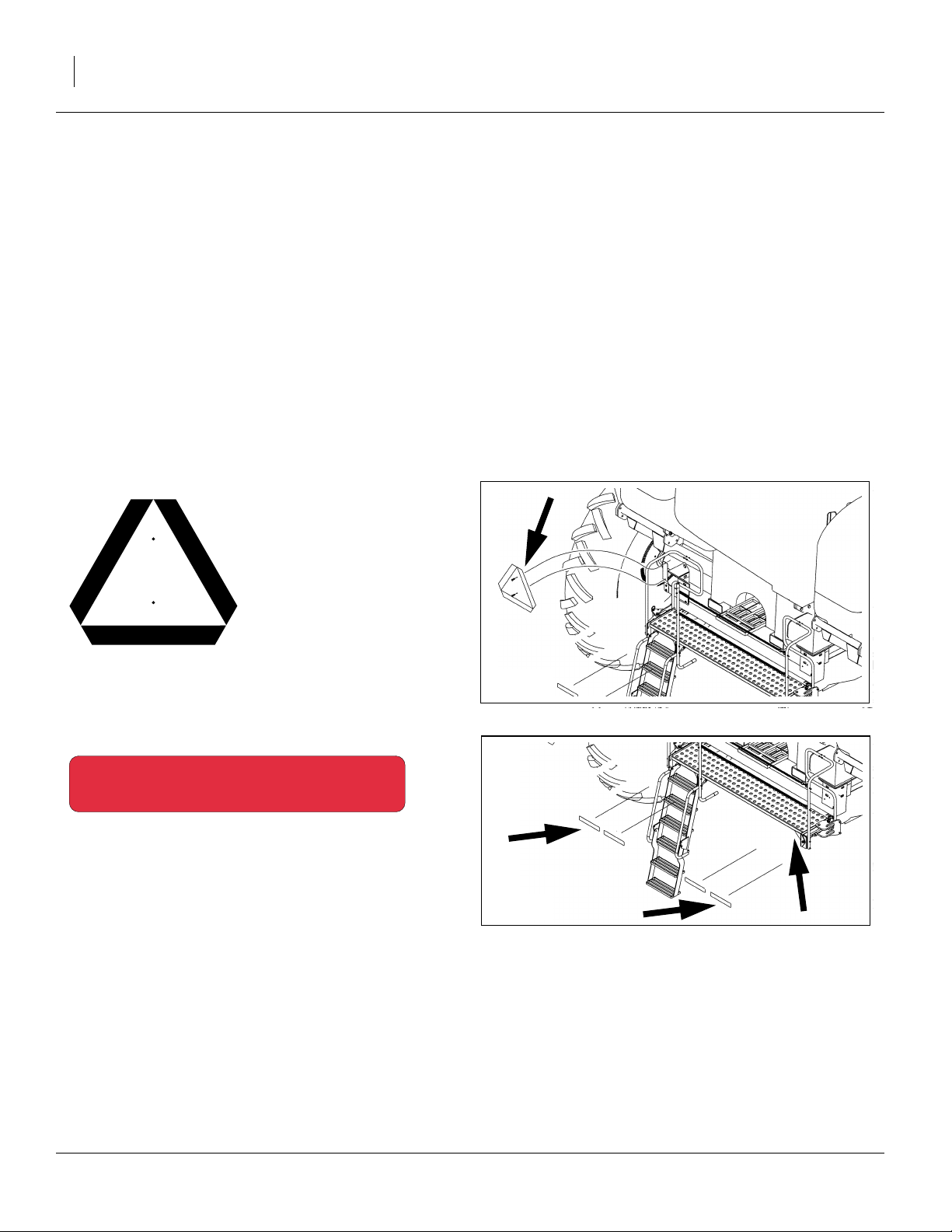
Slow Moving Vehicle Reflector
On the back of the planter, one total
838-266C
Red Reflectors
On the back of walkboard each end and on the backside
of each light mounting bar, four total
27287
27287
401-226M 07/09/2009
Page 11
Great Plains Manufacturing, Inc. 7
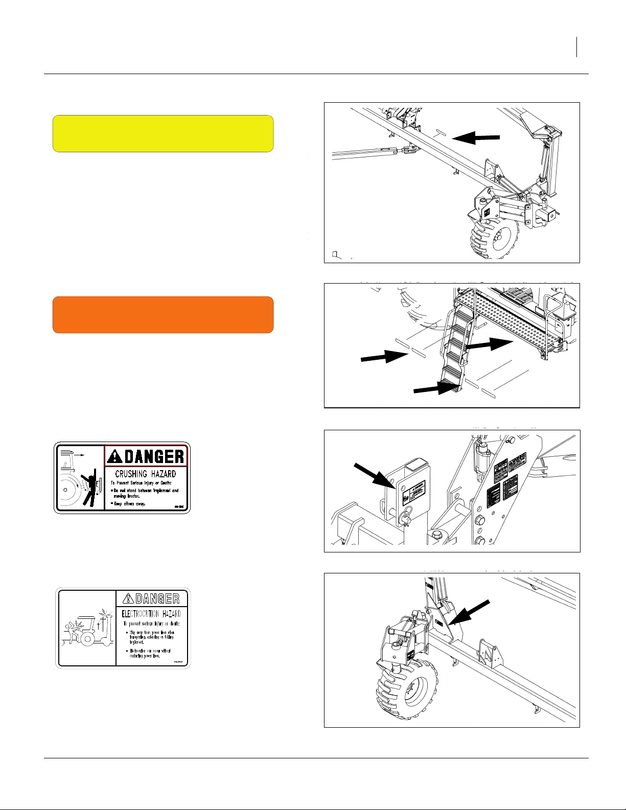
838-265C
Amber Reflectors
On the left-hand wing by drive, two on each side of frame
when folded and two on the front of the light brackets,
seven total
21963
838-267C
Daytime Reflectors
On the back of walkboard each end and on the backside
of each light mounting bar, four total
818-590C
Danger: Crushing Hazard
On the hitch, one total.
838-599C (Option)
27287
27282
Warning: Electrocution Hazard
On marker section each end, two total
27283
07/09/2009 401-226M
Page 12
8 YP1225 and 1625 Great Plains Manufacturing, Inc.
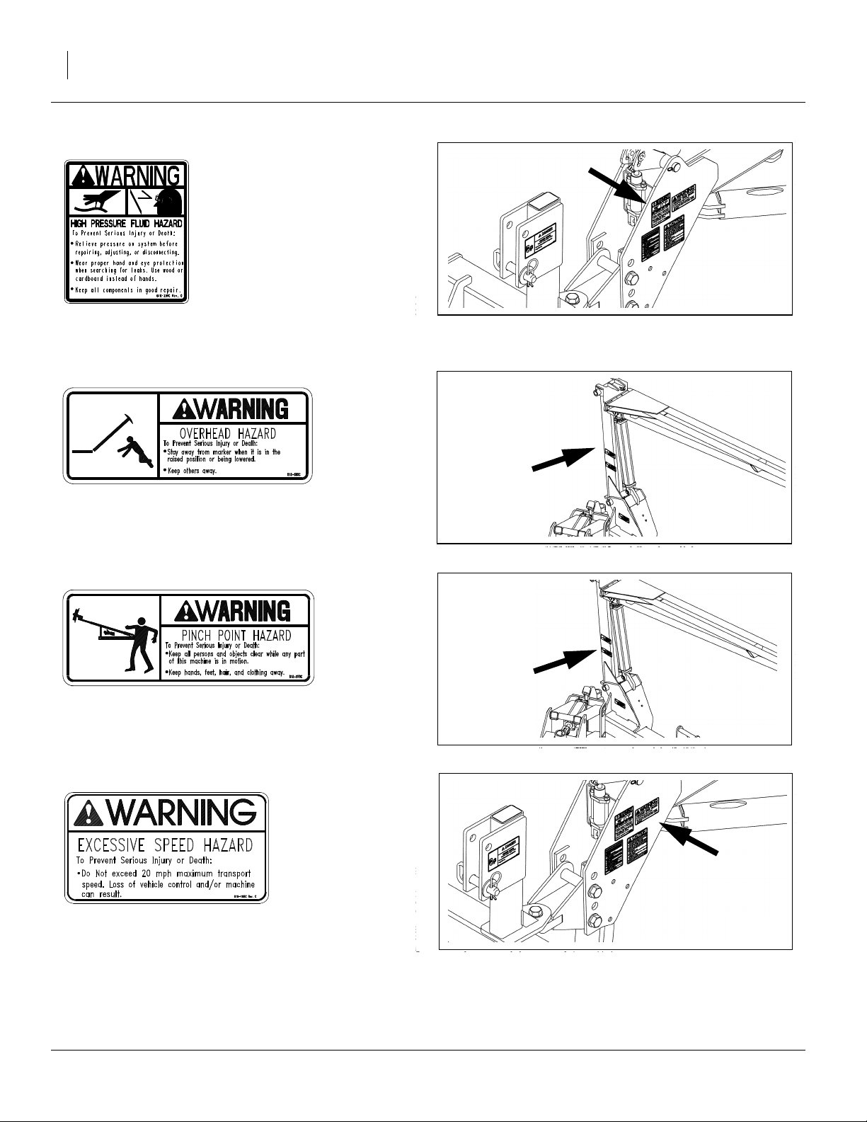
818-339C
27282
Warning: High Pressure Fluid Hazard
On the tongue, one total
818-580C (Option)
Warning: Overhead Hazard
On marker section each end, two total
818-579C (Option)
Warning: Pinch/Shear Hazard
On marker section each end, two total
818-188C
27283
27283
Warning: Excessive Speed
On the tongue, one total
401-226M 07/09/2009
27282
Page 13
Great Plains Manufacturing, Inc. 9
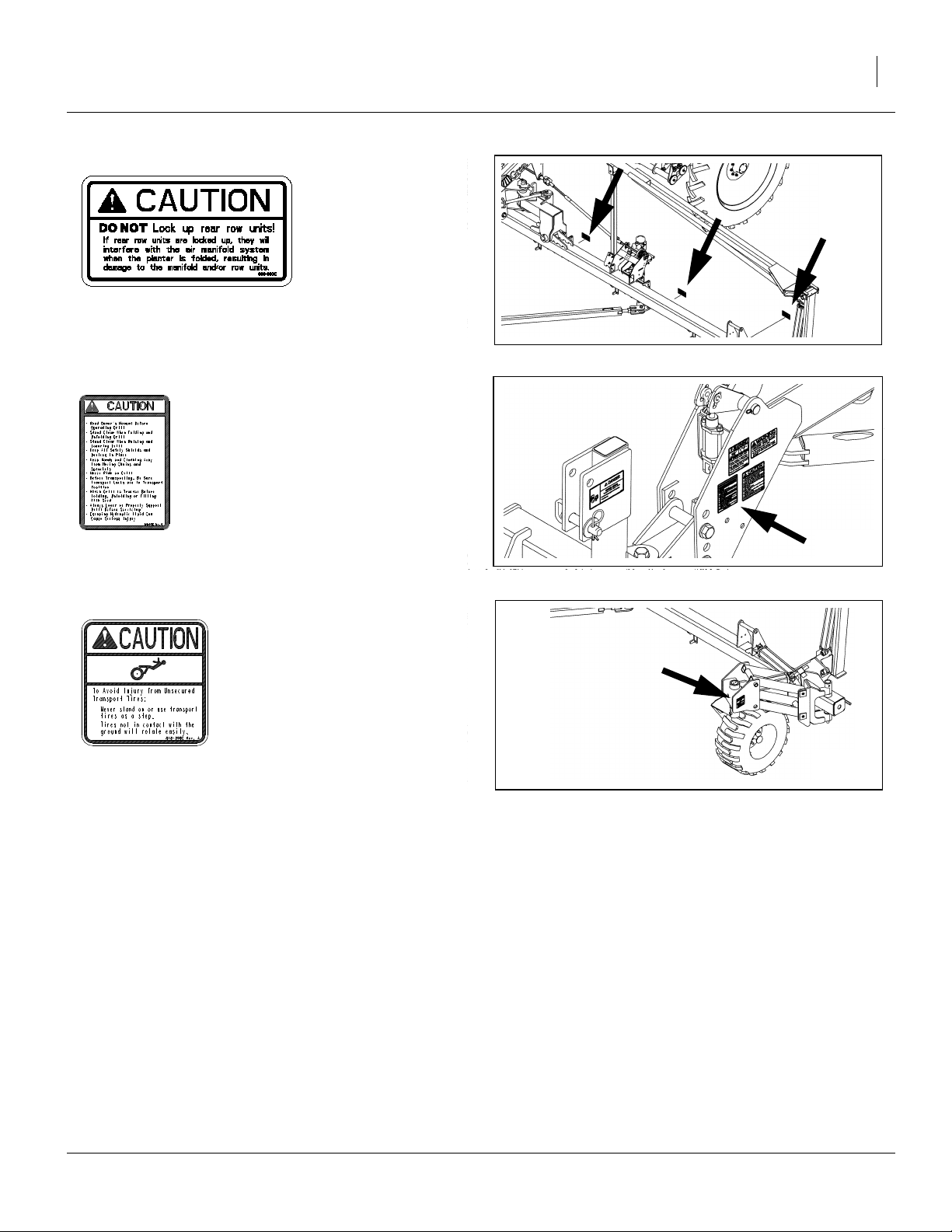
838-993C
Caution: Do Not Lock Up Row Units
Three on backside of each wing, six total
27291
818-078C
Caution: Read Operator Manual
On the tongue, one total
818-398C
Caution: Tires Not A Step
Above both tires, two total
27282
21963
07/09/2009 401-226M
Page 14
10 YP1225 and 1625 Great Plains Manufacturing, Inc.
Introduction
Great Plains welcomes you to its growing family of new
product owners. This planter has been designed with
care and built by skilled workers using quality materials.
Proper setup, maintenance, and safe operating practices
will help you get years of satisfactory use from the
machine.
Description of Unit
The 30- and 40-foot Row Yield-Pro® Planters are pulltype planting implements for use in conventional till, minimum-till, or light no-till conditions.
Yield-Pro® Planters are outfitted with 25 Series, sidedepth-control row-units. Optional unit-mounted coulters
make it suitable for light to moderate no-till conditions
only. These Planters fold for transport.
Document Family
401-226M Operator Manual (this manual)
401-347B Seed Rate Manual
401-226P Parts Manual
R
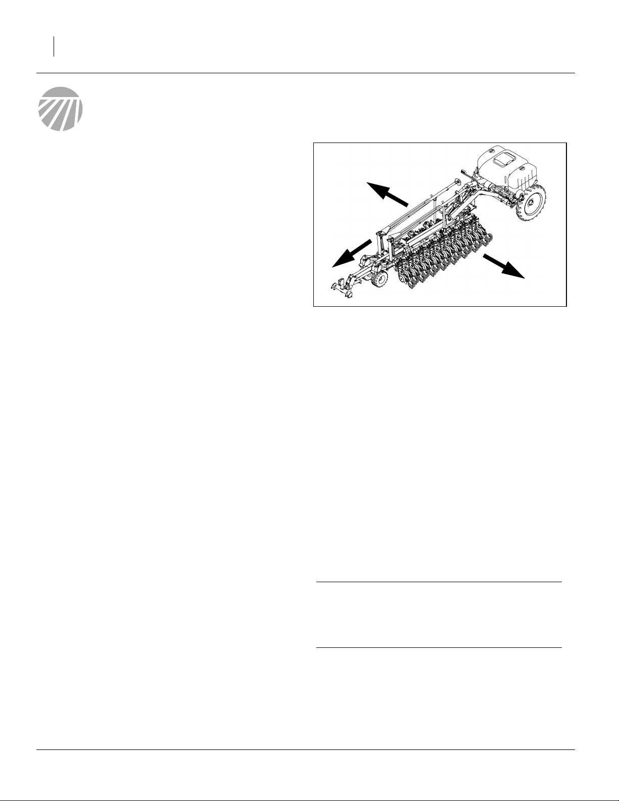
Figure 1
Left/Right Convention
L
27281
Intended Usage
Use the planter to seed production-agriculture crops
only. Do not modify the planter for use with attachments
other than Great Plains options and accessories specified for use with the planter.
Covered Models
YP1225-1230 30-Foot, 12-Row, 30-Inch
YP1225-16TR36 30-Foot, 16-Row (8 Twin), 36-Inch
YP1225-1820 30-Foot, 18-Row, 20-Inch
YP1225-2315 30-Foot, 23-Row, 15-Inch
YP1225-24TR 30-Foot, 24-Row, (12 Twin) 30-Inch
YP1625-1236 40-Foot, 12-Row, 36-Inch
YP1625-1630 40-Foot, 16-Row, 30-Inch
YP1625-2420 40-Foot, 24-Row, 20-Inch
YP1625-24TR36 40-Foot, 24-Row (12 Twin), 36-Inch
YP1625-3115 40-Foot, 31-Row, 15-Inch
YP1625-32TR 40-Foot, 32-Row (16 Twin), 30-Inch
Using This Manual
This manual familiarizes you with safety, assembly, operation, adjustments, troubleshooting and maintenance.
Read this manual and follow the recommendations to
help ensure safe and efficient operation.
The information in this manual is current at printing.
Some parts may change to assure top performance.
Definitions
The following terms are used throughout this manual.
Right-hand and left-hand as used in this manual are
determined by facing the direction the machine will travel
while in use unless otherwise stated.
IMPORTANT !
A crucial point of information related to the preceding
topic. Read and follow the directions provided before
continuing, to ensure safety, avoidance of machine
damage, and to achieve desired field results.
Note: Useful information related to the preceding topic.
401-226M 07/09/2009
Page 15
Great Plains Manufacturing, Inc. Introduction 11
Owner Assistance
If you need customer service or repair parts, contact a
Great Plains dealer. They have trained personnel, repair
parts, and equipment specially designed for Great Plains
products.
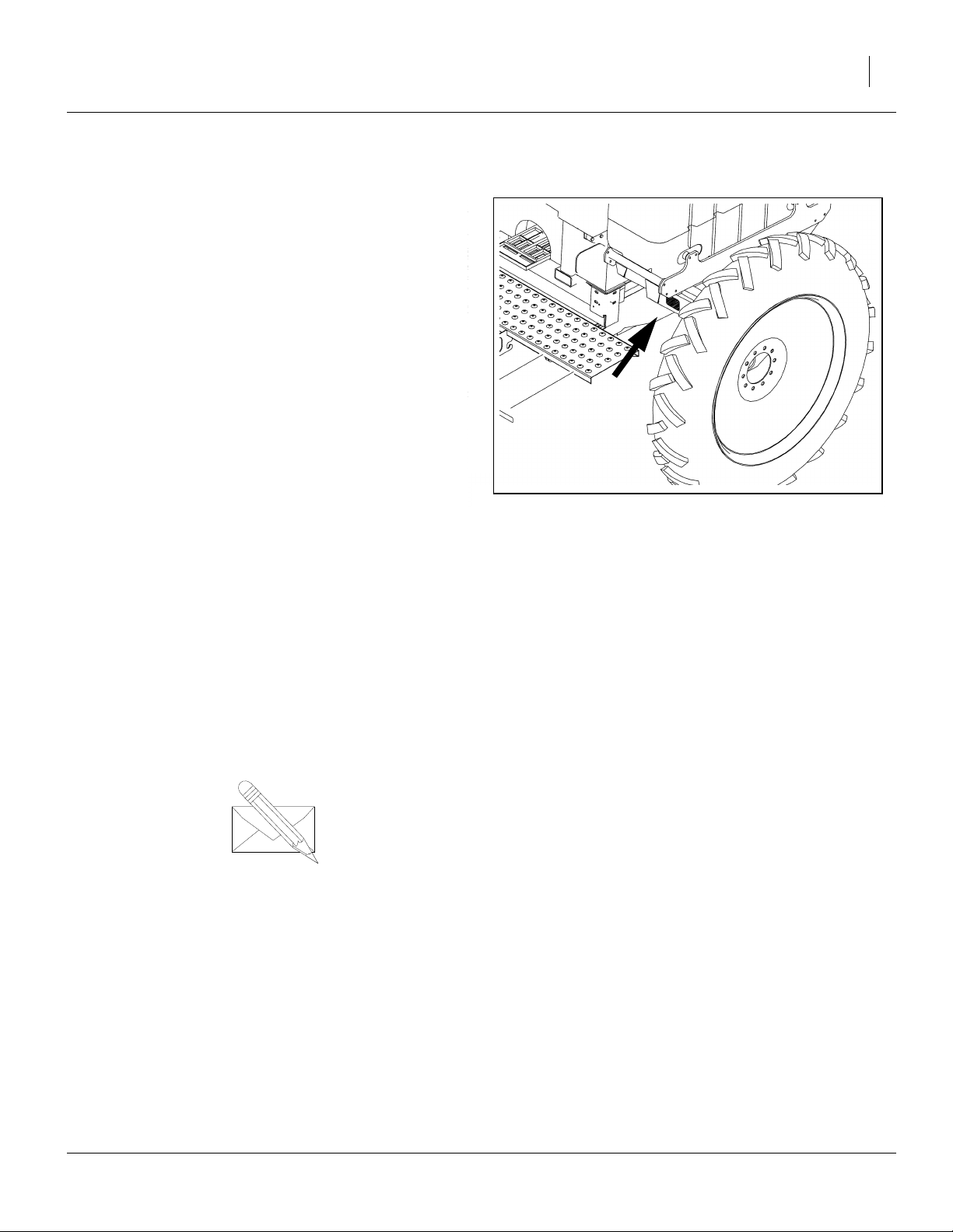
Refer to Figure 2
Your machine’s parts were specially designed and
should only be replaced with Great Plains parts. Always
use the serial and model number when ordering parts
from your Great Plains dealer. The serial-number plate is
located on the front face of the left wing rest, as shown.
Record your Yield Pro Planter model and serial number
here for quick reference:
Model Number:__________________________
Serial Number: __________________________
Your Great Plains dealer wants you to be satisfied with
your new machine. If you do not understand any part of
this manual or are not satisfied with the service received,
please take the following actions.
1. Discuss the matter with your dealership service
manager. Make sure they are aware of any problems so they can assist you.
Figure 2
Serial Number Plate
27284
2. If you are still unsatisfied, seek out the owner or
general manager of the dealership.
For further assistance write to:
Product Support
Great Plains Mfg. Inc., Service Department
PO Box 5060
Salina, KS 67402-5060
07/09/2009 401-226M
Page 16
12 YP1225 and 1625 Great Plains Manufacturing, Inc.
Preparation and Setup
This section helps you prepare your tractor and planter
for use. Before using the planter in the field, you must
hitch the planter to a suitable tractor and level the planter.
Pre-Start Checklist
1. Read and understand “Important Safety Information” on page 1.
2. Check that all working parts are moving freely, bolts
are tight, and cotter pins are spread.
3. Check that all grease fittings are in place and lubricated. See “Lubrication” on page 76.
4. Check that all safety decals and reflectors are correctly located and legible. Replace if damaged. See
“Safety Decals” on page 6
5. Inflate tires to pressure recommended and tighten
wheel bolts as specified. See “Tire Inflation” on
page 118.
Protecting Hydraulic Motor Seals
Low Pressure (Case) Drain Connection
IMPORTANT !
Case Drain Hose must be attached prior to inlet and
return hoses being connected. Also, it must be
unhooked last to prevent damage to the fan motor.
1. Attach case drain hose to low pressure drain connection.
Note: Case drain hose must be hooked up first. Also, it
must be unhooked last to prevent damage to
hydraulic motor seals.
2. Connect low pressure return hose to low pressure
return connector.
Hydraulic Hose Hookup
Great Plains hydraulic hoses are color coded. Hoses that
go to the same remote valve are marked with the same
color.
Color Hydraulic Function
White Fold/Marker
Blue Lift/Tongue
Orange Fan
Yellow Hydraulic Drive
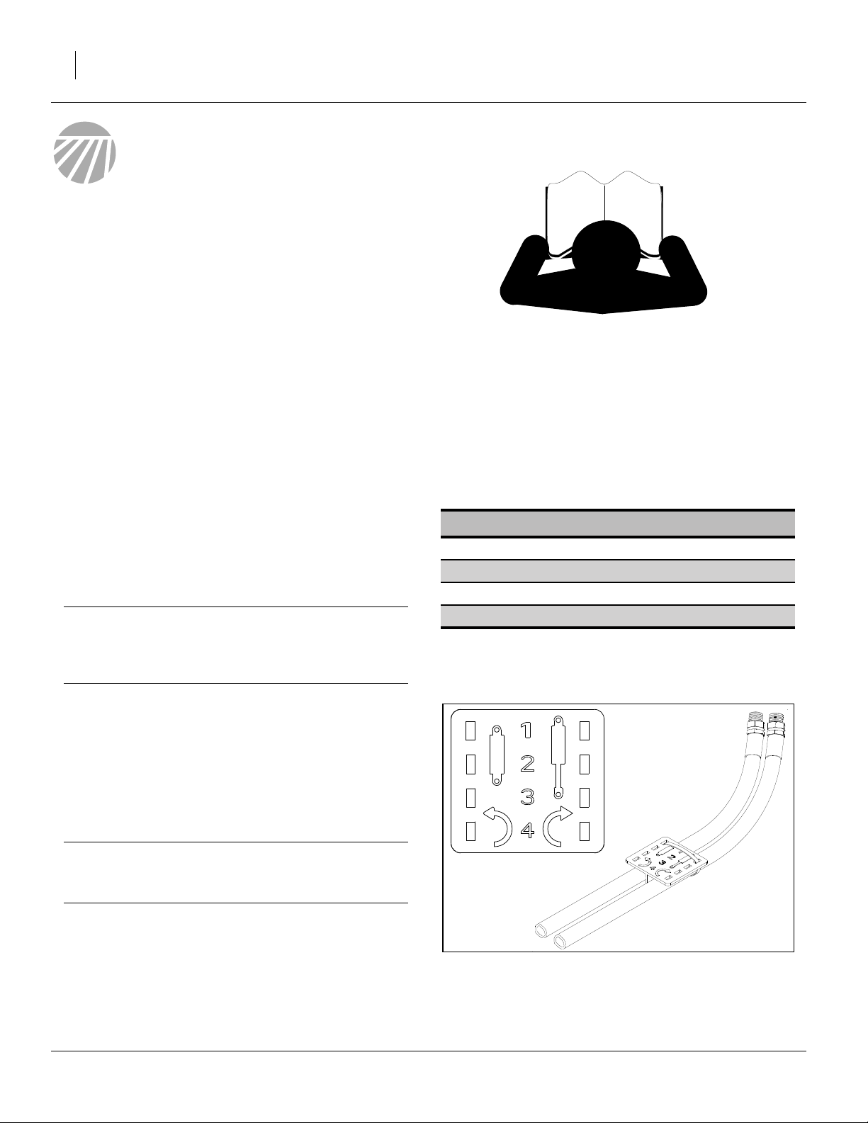
To distinguish hoses on the same hydraulic circuit, refer
to plastic hose label. Hose under extended-cylinder symbol feeds cylinder base ends. Hose under retracted-cylinder symbol feeds cylinder rod ends.
IMPORTANT !
DO NOT hook case drain line to a “power-beyond
port”.
3. If the tractor has a limited number of remotes capable of continuous flow, use them for the hydraulic fan
and optional hydraulic drive. (See “Specifications
and Capacities” on page 118 for tractor requirements.)
401-226M 07/09/2009
Figure 3
Plastic Hose Label
817-348C
17641
Page 17
Great Plains Manufacturing, Inc. Preparation and Setup 13
Hitching Tractor to Planter
!
DANGER
You may be severely injured or killed by being crushed
between the tractor and planter. Do not stand or place any
part of your body between planter and moving tractor. Stop
tractor engine and set park brake before attaching cables and
hoses.
!
WARNING
Escaping fluid under pressure can have sufficient pressure to
penetrate the skin causing serious injury. Avoid the hazard by
relieving pressure before disconnecting hydraulic lines. Use a
piece of paper or cardboard, NOT BODY PARTS, to check for
leaks. Wear protective gloves and safety glasses or goggles
when working with hydraulic systems. If an accident occurs,
seek immediate medical attention from a physician familiar
with this type of injury.
1. If returning the planter to service from storage,
remove any grease used to protect cylinder rods.
3-Point Hitch
Refer to Figure 4
2. Connect your tractor 3-point to the planter 3-point
hitch. If using quick hitch be sure planter locks into
hitch securely.
3. Raise tractor 3-point just enough to relieve pressure
off of the parking stand.
IMPORTANT !
Adjust 3-point hitch arms and sway blocks to minimize
any side-to-side sway to assure proper tracking in the
field and safe road travel.
4. Connect hydraulic hoses to tractor remotes. See
“Hydraulic Hose Hookup” on page 12
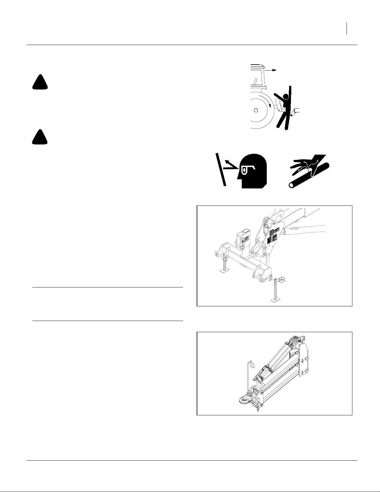
Hydraulic Tongue Hitch
Refer to Figure 5
1. Connect the hydraulic hoses for the tongue circuit.
This needs to be done before hitching in order to
raise and lower the tongue.
2. Set the tongue height to clear the drawbar, back the
tractor into alignment and pin the drawbar.
Figure 4
3-Point Hitching
27282
Figure 5
Hitching with Hydraulic Tongue
07/09/2009 401-226M
25231
Page 18
14 YP1225 and 1625 Great Plains Manufacturing, Inc.
Either Hitch
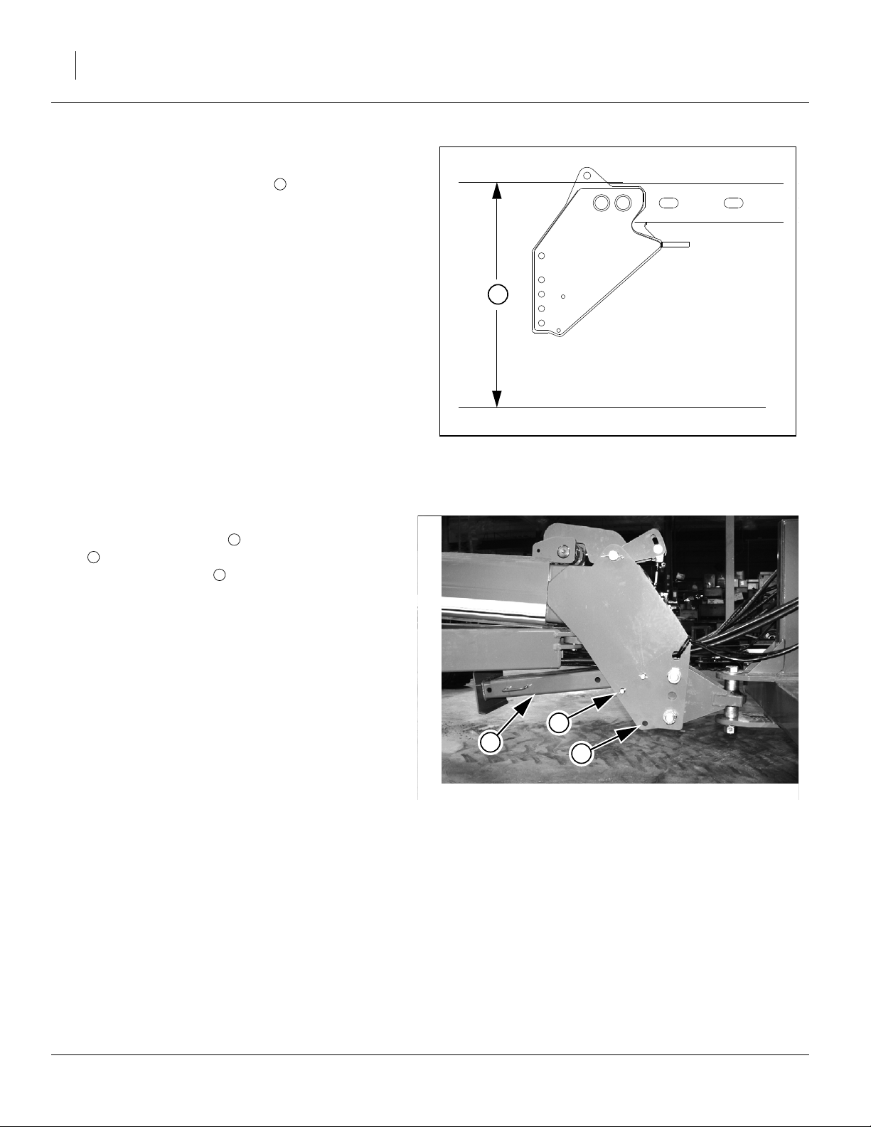
3. Set the initial tongue height, using 3 point or cylinder
of hydraulic tongue. Distance , measured at top of
tongue tube is:
46in above ground level for YP12, or
42in above ground level for YP16.
4. Connect other hydraulic hoses to tractor remotes.
See “Hydraulic Hose Hookup” on page 12
5. Plug the planter light cable to the tractor.
6. Connect monitor lead to monitor harness.
7. Plug electric clutch cable to the switch control box
cable.
8. Plug Veris Drive cable to the cable from the precision
population controller.
Note: Switch control boxes should be mounted in your
tractor cab in a location with easy access. Route
wiring harnesses with enough slack to allow for
tractor movement, especially on articulating tractors.
1
1
Figure 6
Base Height
25316
Refer to Figure 7
9. Remove the lower pin holding the parking stand
3
. Swing the parking stand back and up until it is
above the rear hole . Place the holding pin in the
rear hole and allow the parking stand to rest on it.
This will be the transport position for the parking
stand.
10. Adjust the top link of a 3-point long enough so the
ball swivel does not bottom out when fully raised.
11. Secure hoses so they do not get caught in ball
swivel. Failure to do so could cause hose to be
crushed requiring hose replacement.
2
4
4
3
2
Figure 7
Storing Parking Stand
22813
401-226M 07/09/2009
Page 19
Great Plains Manufacturing, Inc. Preparation and Setup 15
Hydraulic Charge and Bleed
Normally the hydraulic system is fully charged and bled
at the factory before shipping. If repairs have been made,
substantial amounts of oil drained from the system, or
the following procedures do not correct a problem, see
“Bleeding Hydraulics” on page 70.
Lift Hydraulics
Bleeding should not be required other than to raise fully
and hold lever on for one minute or until all cylinders
extend fully. If this does
Cylinder Hydraulics
Bleeding should not be required other than to fold fully
and hold lever on for one minute or until all cylinders
reach the end of their stroke.
IMPORTANT !
Do not fold or unfold without first raising planter completely.
Leveling Frame Side-to-Side
All frame sections must be level to maintain even planting depth. Before using the planter in the field, follow
these steps to make sure the planter is level side-to-side.
Periodic frame-leveling adjustments should not be necessary, but if you are having problems with uneven
depth, check planter levelness and follow these procedures.
Before making any adjustments be sure the lift cylinders
are re-phased and operating properly.
Complete the steps under “Hydraulic Charge and
Bleed” on page 15, before proceeding.
Note: Level frame in planting conditions. Failure to do so
may result in machinery not producing desired results.
Refer to Figure 8
1. Unfold the planter fully and set down. Put in field
position by lowering and pulling forward.
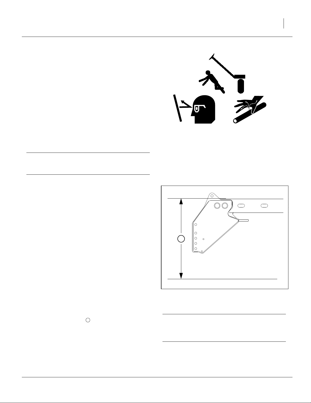
2. When setting hitch, lower lift cylinders completely.
Set the 3-point hitch or hydraulic tongue so that the
top of the tongue tube is:
46in above ground for YP12, or
42in above ground for YP16.
This is the starting point for adjustments.
1
1
Figure 8
Base Height
IMPORTANT !
Planter must be fully lowered to field position and
hitch height must be set before making side-to-side
adjustments.
25316
07/09/2009 401-226M
Page 20
16 YP1225 and 1625 Great Plains Manufacturing, Inc.
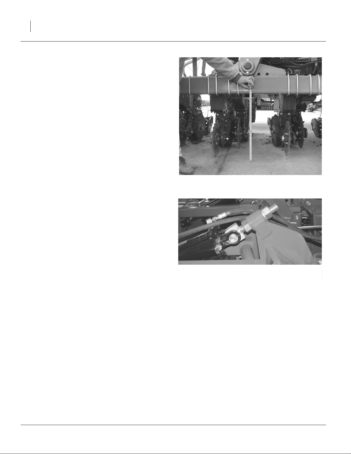
Refer to Figure 9
3. If planting 1
1
⁄
in deep, adjust the hitch until frame
2
measures approximately 26in from ground to frame
at the pivots.When planting at other depths, frame
height will vary.
Note: Parallel arms should be parallel with ground or up
to 1in lower in back. Adjusting a 3-point hitch to level parallel arms may cause frame to sit higher or
lower than 26in.
4. Check parallel arms behind the pivots to ensure that
parallel arms are parallel with ground or up to 1in
lower in back. If needed, raise or lower the 3-point to
adjust parallel arms.
5. Once parallel arms are parallel with ground or up to
1in lower in back and 3-point is set, measure distance from ground to frame at the pivots.
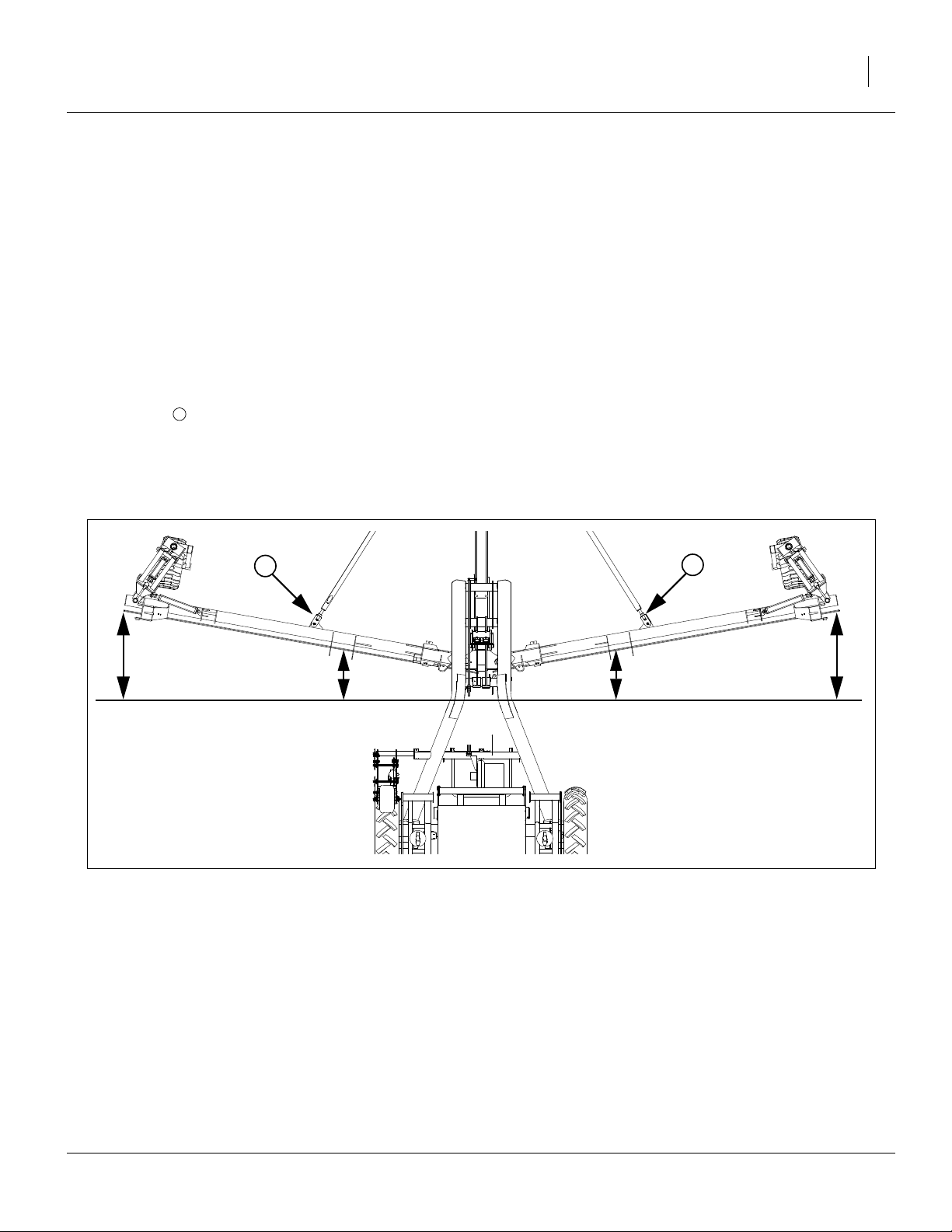
Refer to Figure 10
6. Measure wings at gauge wheel. If not level with center of frame, adjust eye bolt accordingly.
Note: Eye-bolt adjustments are easier if the planter is first
lowered to the ground to remove some of the force
on the cylinder.
Figure 9
Frame Leveling
Figure 10
Eye Bolt Adjustment
23087
21930
401-226M 07/09/2009
Page 21
Great Plains Manufacturing, Inc. Preparation and Setup 17
Wing Alignment
To check and adjust wing alignment:
1. Unfold planter, see “Unfolding the Planter” on page 22, and place a block ahead of each wing gauge wheel. Pull
planter forward against blocks to rock frames back.
Refer to Figure 11
2. Check for proper alignment by running a string line
across back of planter toward outer ends of wings.
For proper alignment, outside ends of wings (dimen-
sion A) should be 0-to(dimension B).
3. To adjust wing alignment, shorten or lengthen eye
bolts to change the length of the wing pull bar. Adjust
eye bolts in or out until dimension A is 0 to
1
greater than dimension B.
4. Be sure both wings are adjusted equally or the
planter will tend to pull sideways behind the tractor.
1
⁄
in ahead of inside ends
4
1
⁄
in
4
Note: Angle of wings is exaggerated for ease of clarifica-
tion.
1
Figure 11
1
21931
Box Alignment
07/09/2009 401-226M
Page 22

18 YP1225 and 1625 Great Plains Manufacturing, Inc.
Optional Monitor Mounting Plate
The Yield-Pro Planter® is supplied with an optional
mounting plate that may be used to mount the Point Row
Monitor, the Electro-hydraulic Control Valve, the Veris
Monitor, and the DICKEY-john® Monitor.
Refer to Figure 12
1. If equipped with Veris, remove suction cups and
mounting bracket from veris monitor. Keep suction
cups and bracket for reuse.
2. Attach large suction cup included with mounting
plate to the top hole on the plate using bolt and lock
washer.
3. If not equipped with Veris, skip this step and continue
with step 4. If equipped with Veris, using lock washers and nuts secure suction cups removed in step 1
to plate. Secure suction cups to holes directly above
the bottom two holes on the plate.
4. Place DICKEY-john® mounting bracket on mounting
plate. Secure bracket to plate in bottom two holes
directly below the suction cups. Use bolts and nuts to
install.
5. If equipped with Veris, attach Veris Drive mounting
bracket above DICKEY-john® mounting bracket
using the included bolts and nuts.
6. Remove mounting bracket from electro-hydraulic
valve control. Install mounting bracket to mounting
plate.
7. Attach point row monitor to mounting plate with 10-
5
32 x
⁄
machine screws, lock washers, and nuts. Let
8
wires fall in the front of the plate.
8. Secure electro-hydraulic valve control to mounting
bracket on plate using 10-32 x
5
⁄
machine screws,
8
lock washers, and nuts. Let wires fall in the front of
the plate.
9. Mount veris drive monitor to mounting bracket on
plate. Secure veris drive monitor to bracket using 1/
4-20 x
5
⁄
8
bolts,
1
⁄
in lock washers, and
4
1
⁄
-20 nuts.
4
Wires should fall in the front of the mounting plate.
10. Attach DICKEY-john® Monitor to DICKEY-john®
mounting bracket on plate. Thread monitor wires
through slot in plate. Trap all other wires between
DICKEY-john® monitor and mounting plate.
Point Row
Monitor
Electro-hydraulic
Valve Control
Figure 12
Optional Monitor Mounting Plate
Veris Drive
Monitor
DICKEY-john®
Monitor
23283
401-226M 07/09/2009
Page 23

Great Plains Manufacturing, Inc. Operating Instructions 19
Operating Instructions
This section covers general operating procedures. Experience, machine familiarity and the following information
will lead to efficient operation and good working habits.
Always operate farm machinery with safety in mind.
Pre-Start Checklist
!
WARNING
Escaping fluid under pressure can have sufficient pressure to
penetrate the skin. Check all hydraulic lines and fittings before
applying pressure. Fluid escaping from a very small hole can
be almost invisible. Use paper or cardboard, not body parts,
and wear heavy gloves to check for suspected leaks. If an accident occurs, seek immediate medical attention from a physician familiar with this type of injury.
1. Carefully read “Important Safety Information” on
page 1.
2. Lubricate planter as indicated under “Lubrication”
on page 76.
3. Check all tires for proper inflation. See “Tire Infla-
tion” on page 118.
4. Check all bolts, pins and fasteners. Torque as shown
in “Torque Values Chart” on page 119.
5. Check planter for worn or damaged parts. Repair or
replace parts before going to the field.
6. Check hydraulic hoses, fittings and cylinders for
leaks. Repair or replace before going to the field.
7. Be sure hydraulic hoses are securely held out of the
ball swivel area at hitch. Failure to do so could cause
hoses to pinch requiring hose replacement.
07/09/2009 401-226M
Page 24
20 YP1225 and 1625 Great Plains Manufacturing, Inc.
Folding the Planter
1
!
WARNING
Pinch Point and Crushing Hazard. To prevent serious injury or
death:
▲ Fold only if hydraulics are bled free of air and fully charged
with hydraulic oil.
▲ Stay away from frame sections when they are being raised
or lowered.
▲ Keep away and keep others away when folding or unfolding
planter.
Fold planter on level ground with tractor in neutral. If your
planter has markers, be certain they are folded.
IMPORTANT !
Center section of planter will move backward while folding. Allow at least 10ft of clearance behind the planter
when folding.
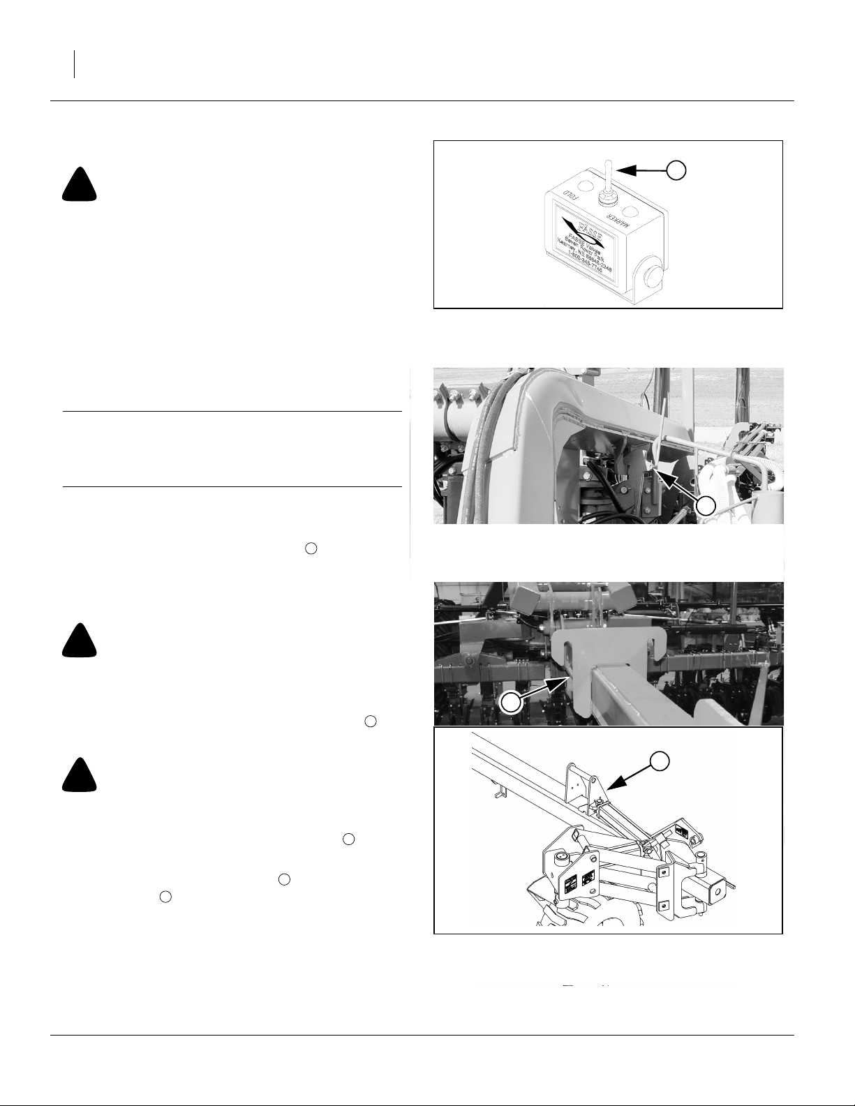
Figure 13
Selector Switch
21980
1. Switch drive line clutches off.
Refer to Figure 13
2. Set electronic valve selector switch in tractor to
“FOLD” to activate fold cylinder hydraulics.
3. Activate lift hydraulics. Raise planter until lift hydraulics are fully raised.
!
CAUTION
Be sure planter’s lift hydraulics are fully raised before folding
or machine damage WILL occur.
Refer to Figure 14
4. Fold planter until wings clear transport hooks by a
few feet.
!
CAUTION
Failure to keep the 3-point lowered while folding WILL result
in opener or seed delivery system damage.
5. Raise 3-point hitch to elevate wing hooks located
on the tongue above the wings.
6. Fold planter fully so wing locks can engage the
wing hooks .
Refer to Figure 15
7. Lower 3-point hitch to engage wing hooks so tongue
is carried on the wing locks. Allow hitch to float with
planter frame while transporting.
3
1
2
3
4
Figure 14
Transport Hooks
3
Figure 15
Wing Hook & Wing Lock
2
25030
4
22815
27288
401-226M 07/09/2009
Page 25
Great Plains Manufacturing, Inc. Operating Instructions 21
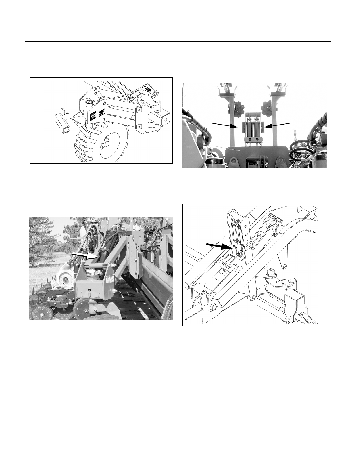
Refer to Figure 17 and Figure 16
8. Remove lift cylinder transport lock channels from
their storage positions.
Figure 17
Transport Cylinder Lock Storage
Refer to Figure 17 and Figure 16
9. Place transport lock channels on lift cylinders
located on gauge wheels and on center frame.
Figure 19
Transport Cylinder Lock Use
27290
25028
Figure 16
Lift Cylinder Lock Storage
Figure 18
Lift Cylinder Lock Use
25029
27289
07/09/2009 401-226M
Page 26
22 YP1225 and 1625 Great Plains Manufacturing, Inc.
Unfolding the Planter
1
!
WARNING
To prevent serious injury or death:
▲ Fold only if hydraulics are bled free of air and fully charged
with hydraulic oil.
▲ Stay away from frame sections when they are being raised
or lowered.
▲ Keep away and keep others away when folding or unfolding
planter.
Unfold planter on level ground with tractor in neutral.
1. Switch drive line clutches off.
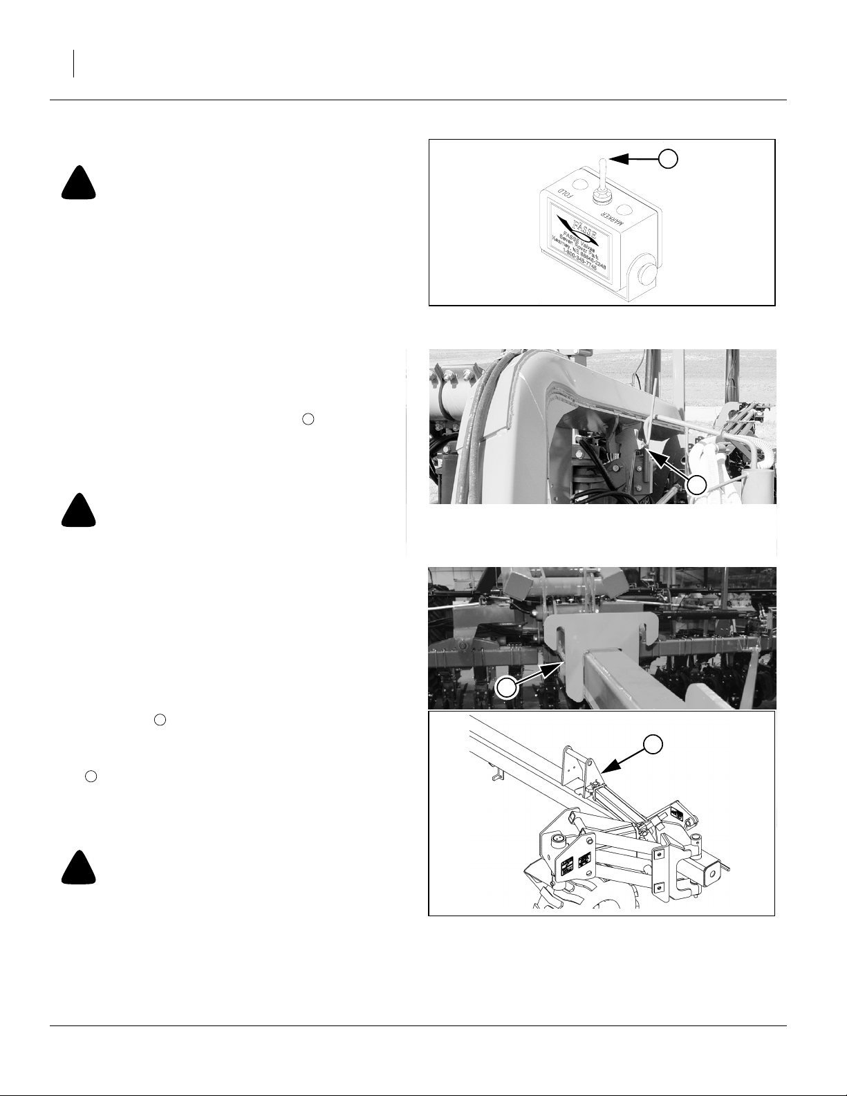
Refer to Figure 20
2. Set electronic valve selector switch in tractor to
“FOLD” to activate fold cylinder hydraulics.
3. Activate lift hydraulics. Raise planter until lift hydraulics are fully raised.
!
CAUTION
Be sure planter’s lift hydraulics are fully raised before unfolding or machine damage WILL occur.
Refer to Figure 21
4. Raise 3-point hitch to release wing hooks.
5. The fold system uses rephasing cylinders. It is necessary to rephase cylinders so wing gauge wheels
run in their fully rotated positions in front of planter.
To rephase fold cylinders:
Move and hold lever in fold direction for 30 seconds.
This causes wings to push against the tongue trans-
port hooks .
Refer to Figure 22
6. Reverse fold lever until wings clear transport hooks
3
by a few feet.
7. Lower 3-point hitch to planting position. See page 13
and page 28 for correct hitch height and depth control settings.
2
1
Figure 20
Selector Switch
21980
2
Figure 21
Transport Hooks
25030
3
4
!
CAUTION
Failure to lower the 3-point before unfolding WILL result in
opener or seed delivery system damage.
8. Unfold planter fully to planting position.
Wing Hook & Wing Lock
401-226M 07/09/2009
Figure 22
22815
27288
Page 27
Great Plains Manufacturing, Inc. Operating Instructions 23
Refer to Figure 16 through Figure 19 on page 21.
9. Remove lift cylinder transport lock channels from
gauge wheels and center frame. Return transport
lock channels to storage area.
10. Activate lift hydraulics and lower planter.
11. Set electronic valve selector switch in tractor to
“MARKER” to activate marker hydraulics.
1
12. Switch drive-line clutches on.
Changing the Seed Box or Hopper
1. Shut off fan before changing boxes.
2. Park the planter on level ground with enough room to
maneuver a tractor with front-end loader around it.
3. Place tractor in park, shut off engine, and remove the
key.
4. Close the slide gate.
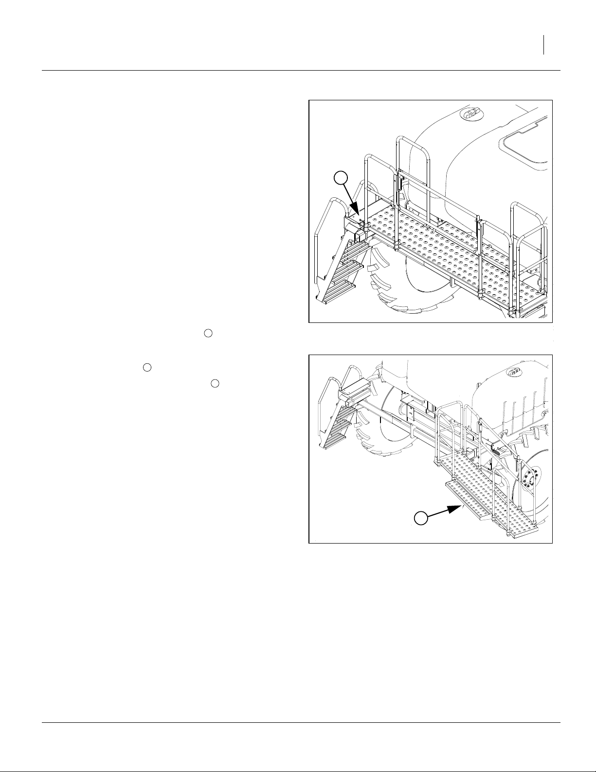
Refer to Figure 23
5. Remove the walkboard lock pin .
1
Refer to Figure 24
6. Swing walkboard all the way to the right.
Note: If planter is lowered, walkboard will stay open by
2
2
itself once fully opened.
Figure 23
Walkboard Lock Pin
24010
2
Figure 24
Walkboard Open
07/09/2009 401-226M
24005
Page 28
24 YP1225 and 1625 Great Plains Manufacturing, Inc.
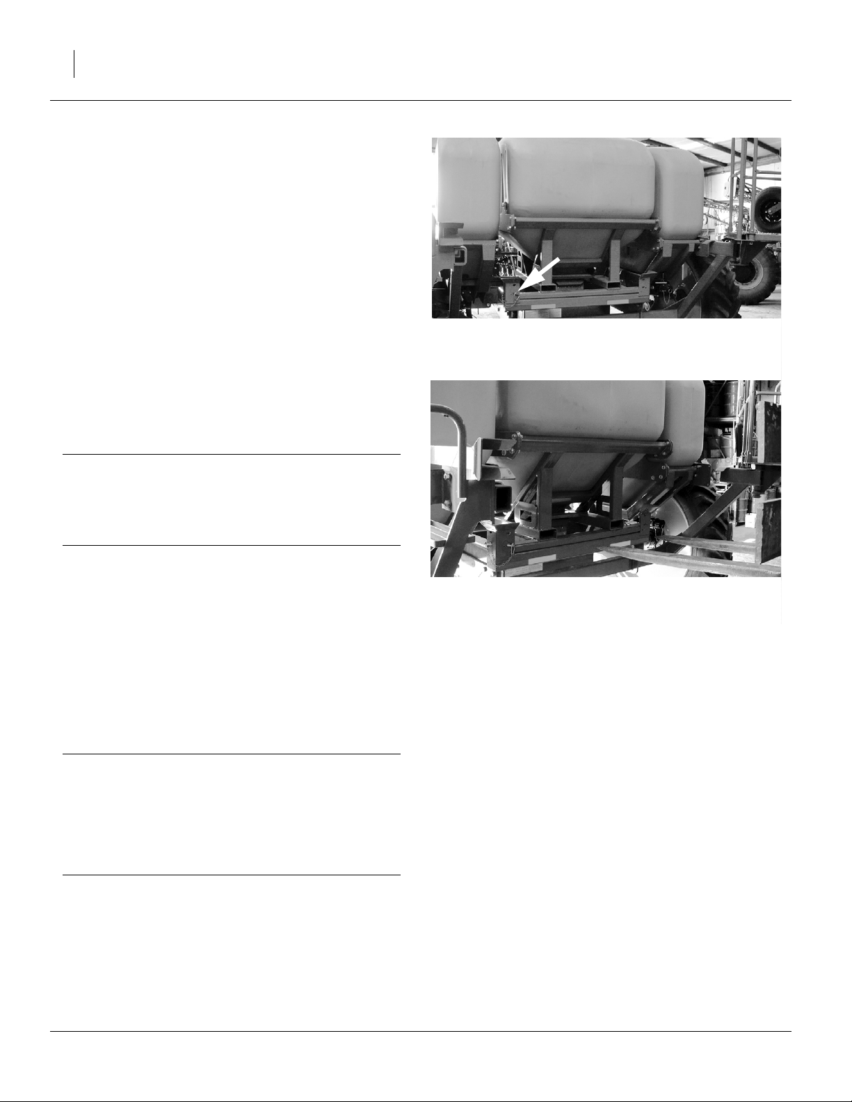
Refer to Figure 25
7. Remove the pins restraining the seed box or bulk
hopper on the frame. (There are two lock pins one
each on diagonal corners).
Refer to Figure 26
Align the forks with the slots in the rear of the seed box or
hopper and slowly drive forward until forks are completely under the seed box or hopper.
Slowly lift the empty seed box or hopper from the planter.
Carefully install a full seed box or an empty hopper on
the planter. Install box restraining pins in opposite corners.
Figure 25
25036
Seed Box Pins
Note: Bulk hopper frame has two sets of lifting points.
One set is for normal loading and is tubes. The other set is to allow picking it up from the side for placing in storage near a wall.
IMPORTANT !
Never attempt to move a seed hopper while loaded. It
exceeds the lifting capacity of front end loaders and
most fork lifts. Always fill seed hopper with seed after it
has been securely placed back on the air box.
Note: It may be necessary to adjust the seal on top of air
box to get full contact with the bottom of seed box or
hoppers. This is a one-time adjustment.
8. Load the hopper with seed. If using a hydraulic auger
with the auxiliary hydraulic kit, refer to the instructions following.
9. Open the slide gate.
10. Return the ladder and platform to the closed position.
IMPORTANT !
Talc lubricant is mandatory for all seeds, especially
treated or inoculated seed when using the precision
meter. Do not use talc lubricant when using the finger
pickup meters. Use graphite lubricant with finger
pickup meters. Refer to “Seed Lubricants” on page
85.
Figure 26
25036
Fork-Lifting Seed Box
Using Auxiliary Hydraulic Circuit
The optional auxiliary hydraulic kit includes a manual
valve that diverts the marker hydraulic circuit to a pair of
quick-connect ports at the back of the seed cart.
1. Extend or fold any marker that is raised. Return the
cab control for that circuit to “off”.
2. Close any shut-off valve on your auger, and connect
the auger to the auxiliary quick-connect ports at the
back of the seed cart.
3. At the auxiliary selector valve (near marker
sequence valve on left wing), move the handle from
“Marker” to “Auxiliary”.
4. With no seed present, open the auger shutoff valve,
and operate the cab control to determine which setting (“extend” or “retract”) turns the auger in the correct direction for seed lift.
5. Load seed. Shutoff cab circuit, then auger. Return
Aux valve control handle to “Marker” position.
401-226M 07/09/2009
Page 29

Great Plains Manufacturing, Inc. Operating Instructions 25
Pre-Usage Checklist
Use the following checklist as a guide to ensure the
planter is proper set before using. You may need to refer
to the assembly instructions, operator’s manual or the
Dickey-john manual to complete checklist.
MECHANICAL
❑ 1. Tongue height preset on 3-point.
❑ 2. Front to rear levelness.
❑ 3. End-to-end levelness at gauge wheels.
❑ 4. Toe in of wing frames at pull-bars.
❑ 5. Tongue hook latch operation.
❑ 6. Marker initial length.
AIR SYSTEM
❑ 7. Manifold to Pro-box or poly hopper seal.
❑ 8. Y-splitters turned on to correct rows.
9. Air leaks (small leaks from Pro-box are nor-
❑
❑
❑ 11. Cleanout doors closed at meters.
❑
mal.
10. Hose routings, no sags and no pinched
hoses. (Check both folded and field positions.)
12. Hoses fully connected to meters and
locked.
ROW CLEANERS
22. Check for correct installation of row clean-
❑
❑
❑
ers on all rows if equipped.
23. Check that row cleaners do not catch on
hydraulic hoses.
24. Carefully watch when folding planter the
first time to ensure clearance of row
cleaner.
FERTILIZER
25. Set rate drive sprockets for correct rate.
❑
❑ 26. Check for correct orifice plates.
❑
❑
❑
❑
(Note fertilizer rate is population dependent.
27. Check unused rows are correctly closed
off.
28. Fill system 1/2 full with water and check for
leaks (run pump is possible).
29. Disconnect drive chain if fertilizer is not
used.
30. Check all row unit lines are connected and
discharge nozzles or tubes are clear.
ROW-UNITS
13. Preset depth handles to 7 holes showing
❑
❑
❑
❑ 16. Check coulter alignment to row.
❑ 17. Check closing wheel alignment.
❑
❑
❑ 20. Lock up splitter rows if needed.
❑
07/09/2009 401-226M
above “T”
14. Preset down force springs to 1st notch
(lightest) setting for most conditions, 2nd
notch otherwise.
15. Set all unit mounted coulters to same depth
as opener blades - no deeper.
18. Set closing wheels to first notch (light setting).
19. Check meter drive coupler is engaged for
all desired rows.
21. Check action and contact of side depth
wheels.
❑ 31. Field raise and lower.
❑ 32. Fold/unfold and tongue lock.
❑ 33. Markers.
❑ 34. Solenoid valve.
❑ 35. Fan direction and speed.
❑ 36. Veris drive (if equipped).
HYDRAULIC
Page 30

26 YP1225 and 1625 Great Plains Manufacturing, Inc.
DRIVE
37. Check all chains are lubricated, proper ten-
❑
❑
❑ 39. Check contact wheel pressure.
❑
❑
❑
❑
❑
sion and move freely without kinks or tight
spots. (This is very important for even
metering.)
38. Set range & transmission sprockets for
desired rate.
40. Check action of contact wheel when raising and lowering it makes contact at
ground height.
41. For hydraulic drive set cal number for correct crop and row spacing.
42. For hydraulic drive pre-run system using
cal mode to verify proper hydraulic action.
43. Lubricate slider joints on drive shafts if not
already done.
44. Check operation of electric clutches for
point rows.
METERS
45. Correct meters for desired crop. (Precision
❑
❑
❑
❑
❑ 49. Check timing of meters in Twin Row corn.
❑ 50. Cleanout doors closed.
❑
❑
Finger Pickup or Singulator Plus.)
46. Correct seed wheels for desired crop.
(Wheels for planters are green in color, not
black.)
47. Seed wheels need to be fully seated in
meter.
48. Correct 12 finger or 6 finger units on all
rows for your row spacing. (Can be
checked by looking into cleanout door
opening.)
51. Meter assemblies properly secured in
place.
52. Graphite for Precision Finger Pickup
meters or Talc for Singulator Plus meters
(per manual).
ELECTRICAL
❑ 53. Power up monitor and check settings.
54. Power up and check hydraulic settings if
❑
❑
❑ 56. Check operation of lighting equipment.
not already done.
55. Check operation of selector valve for fold/
makers.
401-226M 07/09/2009
Page 31

Great Plains Manufacturing, Inc. Operating Instructions 27
Transporting
!
WARNING
Towing the planter at high speeds or with a vehicle that is not
heavy enough could lead to loss of vehicle control. Loss of
vehicle control could lead to serious road accidents, injury
and death. To reduce the hazard, do not exceed 20 mph.
Before transporting the planter, follow and check these
items:
• Set the tractor 3-point hitch control for depth control
operation. If the 3-point hitch control is set for load
control, the auto load control response may automatically adjust too high in given circumstances. This will
result with the wing locks disengaging on the road.
• Empty seed box. Empty seed box before transporting
if at all possible.
• The planter can be transported with a full box of grain,
but the added weight will increase stopping distance
and decrease maneuverability.
• Transport planter only while in folded position. Refer to
“Folding the Planter” on page 20 and make sure cylinder lock channels are in place on the gauge wheels.
• Warning lights. Always use warning lights when transporting the planter.
• Road rules. Comply with all federal, state, and local
safety laws when traveling on public roads.
• Clearance. Remember that the planter is wider than
the tractor. Allow safe clearance.
• Transporting with Markers. Always transport markers
in the folded position. Make sure second marker section rests securely on transport carrier.
A
07/09/2009 401-226M
Page 32

28 YP1225 and 1625 Great Plains Manufacturing, Inc.
Field Operation
1. Hitch planter to a suitable tractor. See “Hitching
Tractor to Planter” on page 13.
2. Make sure proper finger pickup or precision meters
are in place and drive couplers are engaged. See
“Meter Installation” on page 58.
3. Make sure all seed meter clean out doors are closed.
See “Cleaning Out Meters” on page 71.
4. Set planting rate. See “Planting Rate” on page 38.
5. Optional Veris Drive. For information on Veris Drive
operation see “Hydraulic Drive Operating Instruc-
tions” on page 94.
6. Set tractor 3-point hitch control for depth control
operation - not load control.
Note: If tractor 3-point hitch control is set for load control,
hitch movement may cause changes in row unit
depth resulting in uneven depth control.
Approximate capacity (in bu) of
82bu hopper, at 10in increments
Figure 27
82 Bu Bulk Hopper
22958
7. Set tongue height with planter lowered - 46in for
YP12 and 42in for YP16. See “Leveling Frame
Side-to-Side” on page 15.
8. Turn on fan. Set tractor hydraulic flow control to
obtain the rpm from this table, as indicated on system monitor.
3800 rpm 2007+ planters using 2007+ 82bu or
150bu hoppers (or older hoppers with the
vent line update)
3500 rpm 2006- planters, or any planter using bulk
seed boxes or unvented hoppers
Note: Refer to page 32 for further information.
9. Pull forward, lower planter, and begin planting.
10. Always lift planter out of ground when turning at row
ends and for other short-radius turns. Planting will
stop automatically as planter is raised.
11. Use tractor hydraulics to raise/lower planter, not tractor 3-point.
Seed Hopper Sensor
Refer to Figure 27 and Figure 28
For planters equipped with optional 82 bu. or 150 bu.
hoppers, an extra level sensor is included. Use Figure 27
or Figure 28, showing capacity, to place it at the level that
suits your operation. Disconnect sensor in manifold and
attach lead to this sensor to use it.
Approximate capacity (in bu) of
150bu hopper, at 10in increments
Figure 28
150 Bu Bulk Hopper
22958
401-226M 07/09/2009
Page 33

Great Plains Manufacturing, Inc. Operating Instructions 29
Monitor Operation
For monitor operation, refer to the DICKEY-john ® manual supplied with this unit.
Refer to Figure 29
The monitor uses a pickup wheel for measuring planter
ground speed. The pickup sensor should be set at a dis-
tance of
1
⁄
16
in to
1
⁄
in from pickup wheel.
8
Electric Clutch Operation
Refer to Figure 30
Electric clutches allow for turning planting off while the
planter is lowered. A clutch for each drive shaft allows for
independent control each of side of the planter. The
clutches are controlled via the in cab control console.
For regular field operation, turn electric clutch switches
on control console to “ON” position. This will activate the
magnet on each clutch and allow clutch shafts to rotate.
To shut off planting on one or both sides to accommodate point row while planter is lowered, turn one or both
switches to “OFF” position.
Figure 29
Pickup Wheel
Figure 30
Electric Clutch Switch
25318
19694
07/09/2009 401-226M
Page 34

30 YP1225 and 1625 Great Plains Manufacturing, Inc.
Electric Clutch Lockup
Refer to Figure 31
In case of electric clutch failure, electric clutches can be
bolted together.
3
1. Align cutouts at bolt holes .
2. Insert M8-1.25x14mm long metric bolts .
Note: Use only 14mm length bolts as provided or ma-
chine damage will occur. Longer bolts will damage
the clutch. Shorter bolts may not effect a lock-up.
3. Unbolt field coil housing and make sure it is
allowed to move freely.
If you observe half the hole obstructed by a metal disc
4
, you are not at a cutout.
If the entire hole is obstructed by a metal disc , you are
not at a cutout.
When at a cutout, the bolt will screw in with minimal
resistance until the bolt head reaches the clutch face.
IMPORTANT !
When lubricating the planter, do not allow lubricant to
enter the clutch, or clutch slippage will result.
1
2
3
4
1
Figure 31
Electric Clutch Lockup
4
Figure 32
Clutch Plate Nearly at Cutout
2
22906
1
26168
Row-Unit Operation
IMPORTANT !
IMPORTANT! Do not back up with row-units in the
ground, because this will cause severe damage and
row-unit plugging.
For information on row-unit adjustments, see “25 Series
Row-Unit Adjustments” on page 47. For more information on troubleshooting row-unit problems, see “Trouble-
shooting” on page 65.
401-226M 07/09/2009
Page 35

Great Plains Manufacturing, Inc. Operating Instructions 31
Marker Operation
Before operating markers, make sure they are properly
bled as described in “Bleeding Hydraulics” on page 70.
Dual markers are equipped with a sequence valve to
control lift sequence. Starting with both markers up, the
sequence is:
1. If the planter is equipped with an auxiliary hydraulic
system, set the selector valve (found near the
sequence valve at the marker base on the left wing)
to “Marker”.
2. Activate tractor hydraulic lever; right marker lowers
while left marker stays up.
3. Reverse hydraulic lever; right marker raises while left
marker stays up.
4. Activate hydraulic lever; left marker lowers while right
marker stays up.
5. Reverse hydraulic lever; left marker raises while right
marker stays up.
6. Pattern repeats.
Folding speed of dual markers is adjusted with adjustment screws on sequence valve body. Because excessive folding speed may damage markers, adjust markers
to a safe folding speed according to “Marker Adjust-
ments” on page 41.
Note: To get both markers in the lowered position at the
same time, activate hydraulic lever to lower one
marker. After marker is lowered, move lever to
opposite position then quickly reverse lever and
hold until other marker is lowered.
Rephasing Lift System
Over a period of normal use the cylinders may get out of
phase. This will cause some planter sections to run
higher than others. If this is the case, it will be necessary
to rephase lift cylinders. NOTE: Lift cylinders can only be
re-phased when planter is unfolded.
To rephase cylinders:
1. Raise the implement completely and hold the
hydraulic remote lever on for several seconds until all
cylinders are fully extended. Do this every 8 to 10
times you raise planter out of ground.
2. When all cylinders are fully extended, momentarily
reverse hydraulic remote lever to retract system
1
⁄
in
2
to maintain levelness.
Rephasing Fold System
Over a period of normal use, the cylinders may get out of
phase. This is evident by wing gauge wheels not running
in their fully rotated positions in front of the planter.
Note: Planter must be folded to re-phase fold system.
Refer “Unfolding the Planter” on page 22, for
instructions on re-phasing fold system.
07/09/2009 401-226M
Page 36

32 YP1225 and 1625 Great Plains Manufacturing, Inc.
Airbox Operation
The function of the airbox is to carry seed to the meter
where seed is blown to the row spacings.
Fan Operation
The fan must hook up to the case drain line first, and it
must be operated with the return oil line connected to a
low back pressure sump return on the tractor. Check with
tractor manufacturer for proper connection of oil sump
return line. A low back pressure quick disconnect is supplied with the planter for ease of connection to the tractor
sump return line.
Use tractor remote hydraulic valve flow control to set fan
speed. Start with flow on low setting. 8 - 12 gpm is average flow.
Note: Do not apply pressure to the return line or operate
with restricted return line or motor seals will be
damaged.
Recommended butterfly valve setting is 0
mended fan speed depends on planter configuration:
°. Recom-
3800 rpm 2007+ planters using 2007+ 82bu or 150bu
hoppers (or older hoppers with the vent line
update)
3500 rpm 2006- planters, or any planter using bulk seed
boxes or unvented hoppers
Do not run the fan at speeds over 4500 rpm or speeds
under 3000 rpm. Fans operating at too high a speed create too much air flow causing seed to plug up the meter
box. Fans operating at too low a speed do not create
enough air flow to push the seed to the meter causing
the seed tube to plug. If air system does not operate suitably with fan speeds between 3000-4500 rpm, see
“Troubleshooting” on page 65, and then “Fan Adjust-
ments” on page 44.
When starting empty you must blow seed out to the
meters for two to four minutes to fill meters.
Note: Before corn planting for the first time at the start of
each season, add
1
⁄
cup graphite to bottom of air-
3
box.
Watch monitor and adjust fan speed by increasing or
decreasing hydraulic flow from tractor.
The monitor has a level sensor located below hopper to
warn when box is empty. This gives three to four acres of
run time before rows start going empty.
Figure 33
22843
Y-Tube
Y-Tubes
Refer to Figure 33
Y-tube gates can be shut off to feed only one row for
planting 30in corn on 15in machines. Corn rows are the
rear set rows.
You can also shut off the Y-tube gates to clean out the air
system and meters. See “Cleaning Out Air System”on
page 72.
401-226M 07/09/2009
Page 37

Great Plains Manufacturing, Inc. Operating Instructions 33
Airbox Troubleshooting
Problem Cause Solution
Single row doesn’t fill or keep up with
other rows.
Both rows on one meter outlet low or
not keeping up with other rows.
Note: This is more likely to occur on
end outlets.
Multiple rows fail for lack of seed. Fan speed too high/too low. Check/adjust fan speed.
Single or multiple hoses plugging just
ahead of airbox.
All rows fail. Lack of seed. Fan speed too high. Adjust fan speed.
1, 2, 3, or more outlets fail.
Outlets can be side-by-side or random.
Plugging may also move from one outlet to another.
Little or no seed to a lot of rows with
heavily treated seed.
Y tube is bent/angled off feed
pipe.
Drop tube to meter is too long,
causing seed to pool and plug
hose or Y-tube.
Blockage in air slot in top of airbox.
Bad hose routing between delivery hose and airbox on wing.
Out of seed. Add seed.
Fan speed too high/too low. Check/adjust fan speed.
Possible air leak. Check for air leak downstream
Foreign matter in seed chamber
in bottom of airbox.
Seed treatment sticky. Add talc to seed to dry out seed treat-
Loosen pipe and spin so the bend is
straight down and Y-tube is not pointing to front or rear of air pipe.
Shorten hose (with planter raised, but
row units lowered, to ensure hose is
not too short).
Clear by using a long skinny tool and
taking hose off through hose outlet.
It may be necessary to take top off airbox to clear junk from slot.
Correct hose routing.
between box and top of meter.
Extremely high populations may
require slightly reduced field speed.
Clean out seed chamber.
ment.
07/09/2009 401-226M
Page 38

34 YP1225 and 1625 Great Plains Manufacturing, Inc.
Fertilizer Tanks (Option)
!
DANGER
Some chemicals will cause serious burns, lung damage and
death. Avoid contact with skin or eyes. Wear proper protective
equipment as required by chemical manufacturer. Avoid prolonged breathing of chemical fumes. Wear respirator as
required by chemical manufacturer. Seek medical assistance
immediately if accident occurs. Know what to do in case of an
accident.
Filling Tanks
Refer to Figure 34
1. Connect nurse-tank hose to quick-fill coupler located
behind the right-hand tank. Lock hose in place with
cam-lock levers.
2. Close valve going to the in-line filter located just
before the pump.
3. Open valves at each tank and at quick-fill coupler.
4. Fill tanks, then close valve at quick-fill coupler, and
disconnect the nurse tank hose.
Note: Always close valve at filter when filling or storing
any liquid in tanks. Failure to do so may allow material to run out of manifold outlets causing contamination from spillage.
Note: Always fill fertilizer tanks to equal levels. If one tank
fills more quickly,shut that tank valve off to raise the
level in the other tank.
Figure 34
Quick-Fill Coupler
22844
Hypro Pump
The liquid fertilizer option uses a Hypro medium pressure pump. For pump operation and pump maintenance,
refer to the Hypro manual. The Hypro manual is supplied
in the liquid fertilizer option package. For fertilizer settings, see the Seed Rate manual.
IMPORTANT !
Do not allow fertilizer to remain in the tanks for
extended periods or settling of material and system
plugging will occur.
401-226M 07/09/2009
Page 39

Great Plains Manufacturing, Inc. Operating Instructions 35
Parking
For information on long-term storage, see “Storage” on
page 36.
1. Fold planter. see “Folding the Planter” on page 20.
Note: Be sure to install cylinder lockup channels. Failure
to do so may result in injury and/or damage to the
planter.
2. Park planter on a level, solid area.
3. To prevent rolling, block tires securely.
!
DANGER
There is not enough weight on parking stand(s) to anchor
planter. Planter wheels must be blocked when unhitching from
tractor. DO NOT unhitch planter while on a steep slope.
4. If equipped, flush, drain, and close all valves on fertilizer system kit.
Refer to Figure 35
3 Point Hitch
5. Remove pin holding parking stand in “UP” position.
Swing stand down. Pin stand in parking position. If
the ground is soft, place a board or plate under the
stand.
6. Remove wire snap lock pin from innermost hole on
park stand mount. Swing support stand from underneath crossbar weldment.
7. Secure 3-point prop stands by inserting previously
removed wire snap lock pin in lower outermost hole
on park stand mount.
8. Lower tractor 3-point until planter is resting on parking stand.
Hydraulic Tongue Hitch
9. Remove hitch pin, pin holding parking stand in “UP”
position.
10. Use tongue cylinder to lift planter high enough to
fully swing down parking stand. Insert locking pin in
parking stand.
11. Use tongue cylinder to lower planter onto parking
stand. Pin parking stand.
12. Use tongue cylinder to lift tongue off tractor drawbar.
Figure 35
Jack and 3-Point Prop Stand
22814
27282
Either Hitch
13. Shut down hydraulics. Unplug hydraulic lines from
tractor. Do not allow hose ends to rest on the ground.
14. Unplug planter light cable from tractor.
15. Unplug monitor harness from console.
16. 3-point: Unhook tractor from planter hitch.
17. Pull tractor away.
07/09/2009 401-226M
Page 40

36 YP1225 and 1625 Great Plains Manufacturing, Inc.
Storage
Store the planter where children do not play. If possible,
store the planter inside for longer life.
1. Remove seed box. See “Changing the Seed Box or
Hopper” on page 23.
2. Thoroughly clean seed and seed treatment residue
from seed meters. See “Cleaning Out Meters” on
page 71, for more information.
3. If your planter is equipped with an optional fertilizer
tank, clean tank and application hoses. Be sure to
follow chemical manufacturer’s instructions when
handling chemicals.
4. Thoroughly clean pump following instructions in the
pump manual.
5. Unscrew caps on end of fertilizer booms and flush
them out. Drain completely and replace caps.
6. Remove any dirt and debris that can hold moisture
and cause corrosion.
7. Lubricate and adjust all roller chains.
8. Smear grease on exposed cylinder rods to prevent
rust. Add a brightly-colored tag at the hitch as a
reminder to de-grease the rods prior to next use (to
avoid any risk that congealed grease might damage
seals).
9. See “Lubrication” on page 76, for lubrication information.
10. Inspect planter for worn or damaged parts. Make
repairs and service during off season.
11. Use spray paint to cover scratches, chips, and worn
areas on the planter to protect the metal.
12. Cover with a tarp if stored outside.
Note: Do not store optional bulk hopper outside on the
ground. Raise it on blocks, securing it in place to
prevent from falling over or blowing around by wind.
Store inside if possible.
401-226M 07/09/2009
Page 41

Great Plains Manufacturing, Inc. Adjustments 37
Adjustments
To get full performance from your Yield Pro Planter, you
need an understanding of all component operations, and
many provide adjustments for optimal field results. Some
of these are covered earlier in this manual.
Even if your planting conditions rarely change, some of
these items need periodic adjustment due to normal
wear.
Adjustment Page The Adjustment Affects
Tongue Height 14 Correct draft load to tractor
Frame Leveling 15 Planting consistency
Wing Alignment 17 Correct and consistent row tracking
Clutch Lock-Up 30 Temporary operation with a failed clutch
Fan Speed 32 Optimal seed flow to meters
Fan Butterfly Valve 44 Compensating for tractor hydraulics
Planting Rate
Ground Drive Sprockets 38 Meter rpm (seed delivery to seed tube)
Ground Drive Contact Wheel 39 Consistent meter rpm
Hydraulic Drive - Refer to Yield Pro Planter Seed Rate manual
Marker Adjustments
Marker Extension 41 Swath alignment
Disk Angle and Orientation 42 Visibility of mark
Marker Speed Adjustment 41 Reliable marker operation
Height Switch Adjustment 42 Correct off/on state of meter drive
Fertilizer Adjustments (Option)
Fertilizer Rate 43 Refer to Yield Pro Planter Seed Rate manual
Fertilizer Relief Valve 63 Balance system protection and material use
Fertilizer Orifice Selection 64 Refer to Yield Pro Planter Seed Rate manual
Frame-Mounted Row Accessories (Options)
Terra-Tine Row Cleaners 45 Row preparation
Coulters 46 Row pre-furrow depth and trash cutting
Vantage I Fertilizer Delivery 46 Fertilizer placement
25 Series Row Unit Adjustments
Row Unit Down Pressure 48 Planting depth uniformity
Row Unit Lock-Up 49 Single/twin-row operation
Row Cleaner Adjustments (Option) 50 Row preparation
Coulter Adjustments (Option) 51 Row pre-furrow depth
Row-Unit Opener Adjustments 52 Seed depth, spacing, coverage
Side Depth Wheels 52 Seed depth
Adjusting Gauge Wheel Scrapers 53 Consistent seed furrow depth
Seed Meter Setup and Adjustment 54 Consistent seed population
Seed Firmer Adjustments (Option) 61 Seed-soil contact
Press Wheel Adjustment 62 Effective soil coverage
Monitor Adjustments - Refer to Seed Monitor manual
07/09/2009 401-226M
Page 42

38 YP1225 and 1625 Great Plains Manufacturing, Inc.
Planting Rate
Adjusting the planting rate requires the following:
1. setting seed rate:
1
3
For ground-drive planters:
checking tire brand and model
adjusting drive speed range sprockets, and
adjusting transmission sprockets,
For hydraulic drive planters, setting monitor
2. preparing seed meters,
3. checking tire pressure.
4. checking planting rate.
Before setting the planting rate, rotate the contact wheel
1
. Check that seed meters, seed tubes, and drives are
working properly and free from foreign material. Check
that tire pressure is set according to the “Specifications
and Capacities” on page 118.
Note: Contact wheel turns in opposite direction than
main ground tire.
1
1
,
Drive Speed Range Sprockets
Select the correct drive speed range sprockets for your
seed by referring to the “Seed Rate Charts” in the seed
rate manual.
Refer to Figure 36
Loosen idler and remove chain . Remove retaining
4
pins from shafts and install speed range sprockets as
necessary.
Note: Make sure the correct sprockets have been in-
stalled in the DRIVING and DRIVEN locations as
shown.
Reroute chain over sprockets and idlers as shown. Move
idler into chain so chain has
span. Tighten idler and install lynch pins.
2 3
1
⁄
in slack in its longest
4
4
4
2
Figure 36
Drive Speed Range
Sprockets Adjustment
21974
2
3
4
4
Transmission Sprockets
To change the planting rate, change the transmission
sprocket combination. Refer to “Seed Rate Charts” in
the seed rate manual.
Refer to Figure 37
Loosen idler and remove drive chain . Remove
lynch pins from shafts and rearrange driving and
driven sprockets as necessary.
1. Ground drive seeding rate can vary as much as 5% due to tread differences. Make sure you have the latest Seed Rate manual that
401-226M 07/09/2009
2 3
4
provides rate tables specific to your main transport tires.
Reroute drive chain over sprockets and idlers as shown.
Move idlers into chain so chain has
est span. Tighten idlers and install lynch pins.
Figure 37
Transmission
Sprockets Adjustment
1
⁄
4
in slack in its long-
21974
Page 43

Great Plains Manufacturing, Inc. Adjustments 39
Contact Wheel Drive
Refer to Figure 38
You can adjust the down pressure the contact wheel
exerts by adjusting the pressure on the spring.
Note: Do not adjust spring so tight that it will bottom out
when raised.
Refer to Figure 39
Before adjusting spring, raise planter and adjust wheel
travel to obtain 1
1
⁄
in clearance above the main tire.
2
Refer to Figure 40
You can adjust the amount of travel for the contact wheel
by loosing the jam nuts and lengthening or shortening
the threaded rod.
Note: This adjustment controls the timing of the seed
meter drive when raising and lowering the planter.
Increasing the gap between the tires causes seed
flow to start and stop with the planter at a lower
height. Decreasing the gap will cause seed flow to
start and stop at a higher position.
Note: Be sure to check for spring bottoming after making
this adjustment.
Figure 38
Down Pressure Spring
Figure 39
Contact Drive Wheel
21973
11⁄2in
22500
Figure 40
21972
Travel Adjustment
07/09/2009 401-226M
Page 44

40 YP1225 and 1625 Great Plains Manufacturing, Inc.
Checking Singulated Planting Rate
The seed charts are based on cleaned and sized seed.
Extreme seed size variations, foreign material and tire
pressure will affect the planting rate. Check the seed
population rate as described below.
1. Adjust the planting depth to a shallow setting.
2. Plant at the desired planting speed for a short dis-
tance.
3. Using the table below, determine how many rows
need to be counted.
4. Measure a distance, according to the table, for the
row spacing in the planted area.
5. Count the number of seeds, in the appropriate num-
ber of rows, over the distance measured.
6. Multiply the number of seeds counted by 200 if mea-
suring for
1
⁄
acre or 1,000 if measuring for
200
1
⁄
1000
acre. This is the plant population in seeds per acre.
Example 1: Single Row
If you have a 10in row spacing planter, according to the
chart, three rows must be counted. Measure 17ft 5in and
count the number of seeds in three rows. If the number
is, for example, 180, multiply 180 by 1,000.
180 1 000,× 180 000 SeedsPerAcre(),=
Example 2: Twin Row
If you have a Twin Row 30in spacing planter, according
to the chart, both rows of the twin row must be counted.
Measure 87ft 1in and count the number of seeds in the
parallel row. If the number is, for example, 170, multiply
by 200.
170 200× 34 000 SeedsPerAcre(),=
If the planting population is significantly different than
desired, make the following checks:
Double check the transmission and range sprocket combinations. Refer to the seed population chart for the seed
being planted.
Check the air pressure in the gauge wheel tire. See “Tire
Inflation” on page 118.
See “Troubleshooting” on page 65.
Seed rate charts
Seed rate charts are in the seed rate book. The charts
give transmission sprocket combination and drive range
sprockets for row spacing used, to achieve the population desired.
Each seed chart has a corresponding page showing the
different drive ranges for that seed and a transmission
sprocket reference.
Note: Use
1
⁄
acre for populations less than 100,000
200
seeds/acre. Use
1
⁄
1000
100,000 seeds/acre.
acre for populations above
Planted row spacing (inches)
Number of rows to
count
Length of row
to measure for
1/1,000 acre
Length of row
to measure for
1/200 acre
7 1/2in 4 17ft 5in
9 1/2in 3 18ft 4in
10in 3 17ft 5in
15in 2 17ft 5in 87ft 1in
19in 2 13ft 9in 68ft 9in
20in 1 26ft 2in 130ft 8in
30in or Twin Row 30in
a
1
17ft 5in 87ft 1in
36in or Twin Row 36in 1 14ft 6in 72ft 7in
38in or Twin Row 38in 1 13ft 9in 68ft 9in
40in or Twin Row 40in 1 13ft 1in 65ft 4in
15in Skip Row 2 15ft 3” 76ft 3in
a. A twin row pair counts as one row.
401-226M 07/09/2009
Page 45

Great Plains Manufacturing, Inc. Adjustments 41
Marker Adjustments
!
CAUTION
You may be injured if hit by a folding or unfolding marker.
Markers may fall quickly and unexpectedly if the hydraulics
fail. Never allow anyone near the planter when folding or
unfolding the markers.
Dual Marker Speed Adjustment
Refer to Figure 41
Adjust folding speed for dual markers with hex adjustment screws on sequence valve body. There is an
adjustment screw for raising speed and one for lowering speed . You can identify adjustment screws by
markings stamped in the valve body.
Turn adjustment screws clockwise to decrease folding
speed and counterclockwise to increase folding speed.
With tractor idling at normal operating speed, adjust
marker folding to a safe speed. Excessive folding speed
could damage markers and void the warranty.
After adjusting folding speed, tighten jam nuts on hex
adjustment screws to hold settings.
2
1
S
2
Figure 41
Marker Extension Adjustment
F
1
S
14048
Marker Extension
Refer to Figure 42
To adjust marker extension:
1. Loosen nuts on U-bolts .
2. Move marker disk tube in or out to get the proper
adjustment.
3. Measure from the end of disk tube to the end of
the second section. This distance should be 10
for 15in row spacing and 25
twin-row spacing. Use the steps below to double
check for your row spacing.
4. To measure for marker width adjustment:
5. Lower planter in the field and drive forward a few
feet.
6. Measure from the middle of the outside row to the
mark in the ground made by marker disk.
Adjust as needed.
4 3
5
5
1
⁄
in for 20in, 30in, and
2
1
⁄
in
2
5
4
Figure 42
Marker Disk Extension
3
18878
07/09/2009 401-226M
Page 46

42 YP1225 and 1625 Great Plains Manufacturing, Inc.
Marker Disk Adjustment
!
CAUTION
Marker disks may be sharp. Use caution when making adjustments in this area.
Refer to Figure 43
To change angle of cut, and the width of the mark, loosen
1
⁄
-inch bolts holding disk assembly.
2
For a wider mark (W), increase the angle of the marker
with respect to the tube . For a narrower mark (N),
reduce the angle.
Tighten bolts .
Note: The direction of travel (T) tends to drive the disk an-
gle to Wide. If bolts are not tight enough, or loosen
over time, the disk will slip into the Wide mark configuration.
6
5
6
5
W
N
6
Figure 43
Marker Disk Angle
T
11757
Hydraulic Drive Height Switch
The optional Hydraulic Drive is supplied with a height
switch that is used to activate the Drive when the
planter is lowered for field operation.
Refer to Figure 44
1. Loosen the bolts holding the height switch bracket
2. Lower the planter to the height at which seed deliv-
3. Rotate the switch towards the frame pivot until the
4. Rotate the switch in until it clicks. Tighten the bolts to
Note: It may be necessary to loosen the screws holding
1
and rotate the switch and bracket away from the
frame pivot .
ery should begin.
spring actuator just touches the frame.
secure it in place. Be sure frame tube will not crush
switch when unit is fully loaded.
the switch and rotate the switch slightly on the
bracket.
3
1
4
4
2
1
2
3
Figure 44
Veris Height Switch
23398
401-226M 07/09/2009
Page 47

Great Plains Manufacturing, Inc. Adjustments 43
Setting Fertilizer Rate
!
DANGER
Some chemicals will cause serious burns, lung damage, and
death. Avoid contact with skin or eyes. Wear proper protective
equipment as required by chemical manufacturer. Avoid prolonged breathing of chemical fumes. Wear respirator as
required by chemical manufacturer. Seek medical assistance
immediately if accident occurs. Know what to do in case of an
accident.
Fertilizer rate is controlled by two factors:
1. Pump rate, and
2. Orifice size at the row unit drop-line points.
Pump rate depends on sprocket setting (and pump drive
type).
Consistent system operation also requires a correctly
adjust relief valve and a well-maintained strainer ahead
of the pump. See “Setting Relief Valve” on page 63 and
“Strainer” on page 63.
Hypro Pump
The liquid fertilizer option uses a Hypro medium pressure pump. For pump operation and pump maintenance
refer to the Hypro manual. The Hypro manual is supplied
in the liquid fertilizer option package.
On new and upgraded planters, the pump is driven by a
ground contact wheel, and fertilizer rate is independent
of seed rate. Fertilizer rate is set by sprockets on the
ground drive assembly. See “Ground Drive Pump” on
page 44.
Note: Great Plains recommends checking with your local
Agronomist as soil conditions vary. Soil conditions
in your area may need lesser or more amounts of
fertilizer than represented in these charts. Do not
exceed 12 gallons per acre in any case.
Note: Always remove pump drive chain when not in use.
Do not operate planter pump when not applying
material.
07/09/2009 401-226M
Page 48

44 YP1225 and 1625 Great Plains Manufacturing, Inc.
Ground Drive Pump
On new and upgraded planters, the pump is driven by
a ground contact wheel , and fertilizer rate is independent of seed rate. Fertilizer rate is set by sprockets on
the ground drive assembly.
Refer to Figure 45
For sprocket settings, see the Seed Rate manual.
2
1
3
3
1
2
3
Fan Adjustments
Recommended fan butterfly valve setting is 0°. Recommended fan speed depends on planter configuration:
3800 rpm 2007+ planters using 2007+ 82bu or 150bu
hoppers (or older hoppers with the vent line
update)
3500 rpm 2006- planters, or any planter using bulk seed
boxes or unvented hoppers
Adjust the basic fan rate with the tractor hydraulic system
and fan rpm display on seed monitor. Do not run the fan
over 4500 rpm or under 3000 rpm.
Fans operating at too high a speed create too much air
flow causing seed to plug up the meter box. Fans operating too slowly do not create enough air flow to push the
seed to the meters, causing the seed tube to plug. If air
system does not operate suitably with fan speeds
between 3000-4500 rpm, refer to the troubleshooting
chart, and then adjust the fan butterfly valve.
The butterfly valve may be helpful if your tractor can
maintain a high, but irregular fan rpm. Set the rpm to
above 3500 rpm with the valve completely open (0°).
Adjust the valve angle in the 20-30° range until you
achieve the desired seed flow consistency.
Figure 45
Ground Drive Pump Sprockets
Figure 46
Fan Butterfly Valve
25319
25267
401-226M 07/09/2009
Page 49

Great Plains Manufacturing, Inc. Adjustments 45
Row Implement Adjustments
To get full performance from your planter, you need a
good understanding of row cleaner, coulter, fertilizer,
opener, meter, seed firmer, and press wheel operation.
Frame-Mounted Row Accessories
Terra-Tine™ Adjustment
Refer to Figure 47
Note: All adjustments must be made with the unit in the
fully raised position.
IMPORTANT !
Check that the Terra-Tine Row Cleaner tines DO NOT
touch the coulter blade or any other attachments. Such
contacts cause excess wear to all parts involved. At
1
least
⁄
in clearance is recommended.
2
1. When the blade is out of the soil, adjust the lock collar height to set the height of tine fingers flush with
the bottom of coulter blade.
2. Side-to-side alignment can be done by rotating the
shank mount around the vertical shaft and retightening the square head set screw.
Refer to Figure 48
3. Fore-to-aft adjustment is accomplished by adding or
removing the extension arm to place the Terra-
1
Tine Row Cleaner to either side of the coulter hub
depending on the desired position or clearance
between other attachments. Testing has shown better performance behind the hub, but available space
may dictate the mounting position.
L.H.
Figure 47
Terra-Tine in Front of Hub
1
R.H.
13469
L.H.
Figure 48
R.H.
13469
Terra-Tine Behind Hub
07/09/2009 401-226M
Page 50
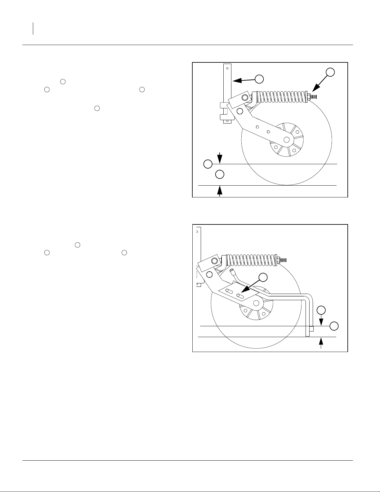
46 YP1225 and 1625 Great Plains Manufacturing, Inc.
Frame-Mounted Coulters
Refer to Figure 49
At the shaft , adjust the coulter depth for a running
depth of 4 to 4
Vantage I manual (204-376M) for further adjustments.
1
2 3
1
⁄
in below ground level . Refer to the
2
1
4
Do not adjust the spring tension. It is factory pre-set.
Vantage I Fertilizer
Refer to Figure 49
At the back plate , adjust the tine height for a running
depth of 1in below ground level . Refer to the Van-
tage I manual (204-376M) for further adjustments.
6 3
5
4
3
2
Figure 49
Frame-Mount Coulter
25392
5
6
3
Figure 50
Vantage I Applicator
401-226M 07/09/2009
22951
Page 51

Great Plains Manufacturing, Inc. Adjustments 47
25 Series Row-Unit Adjustments
Refer to Figure 51, which depicts a 25 Series row unit fully
populated with all options supported on YP1225 and 1625 (excepting Seed-Lok)
1. See “Row-Unit Down Pressure” on page 48. Each
row-unit is mounted on the planter with parallel arms.
This parallel-action mounting allows the row-unit to
move up and down while staying horizontal. A cam
2. See “Row Unit Lock-Up” on page 49. A row unit
may be completely disengaged by locking it in the full
up position.
3. See “Unit-Mount Cleaner Adjustments” on
page 50. Optional row cleaners clear trash from the
row, to a depth set by an adjustment.
4. See “Unit-Mounted Coulter Adjustments” on
page 51. An optional disk coulter cuts remaining
trash and begins opening the seed groove. Its work-
ing depth is set by the side gauge wheels
mounting hole selection.
5. See “Row-Unit Planting Depth” on page 52. Rowunit double disk openers widen the coulter groove,
making a seed bed. They have adjustments for angle
and scraper clearance.
6. See “Side Gauge Wheel Adjustments” on page 52.
Side gauge wheels are the primary control over seed
depth. They have adjustments for depth and angle.
An optional scraper also needs periodic adjustment.
7. See “Meter Exchange and Adjustments” on
page 54. A seed tube mounted between the disks
(not shown) delivers seed to the trench. It is fed by a
seed meter which may have adjustments or interchangeable wheels.
8. See “Seed Firmer Adjustments” on page 61.
An optional seed firmer (Keeton shown) minimizes
seed bounce and improves soil contact. It may also
deliver fertilizer.
9. See “Press Wheels” on page 62.
The press wheels close the furrow, gently pressing
the soil over the seed to ensure good seed to soil
contact for even emergence. They have adjustments
for down-pressure, stagger and angles.
➂ and a
➊
2
3
1
5
4
Figure 51
25 Series Row Unit
6
7
96
8
9
25193
IMPORTANT !
Do not back up with row-units in the ground. This will
cause severe damage and row-unit plugging.
07/09/2009 401-226M
Page 52

48 YP1225 and 1625 Great Plains Manufacturing, Inc.
Row-Unit Down Pressure
Row-unit springs provide the down pressure necessary
for row-unit disks to open a seed trench. The springs
allow the row-units to float down into depressions and up
over obstructions. Springs also provide down force on
coulters when using optional row mounted coulters.
You can adjust down pressure individually for each rowunit. This is useful for penetrating hard soil and planting
in tire tracks. For best results always adjust tractor tires
so they are not ahead of 30in rows.
Use only enough down pressure to cut the seed trench
and maintain proper soil firming over seed. Excessive
row-unit down force will lead to premature wear on rowunit components. Excessive down force will also cause
uneven seed depth.
Figure 52
Row Unit Cam Operation
21948
Refer to Figure 52 through Figure 54
To adjust down pressure, use 1
1
⁄
in open end wrench or
8
tool stored under the walkboard. Position wrench on nut
and pull down. Move adjustment cam to new setting. If
using cast tool stored under the walkboard, be sure row
unit is off the ground to fully relax springs.
Minimum and maximum settings are indicated by position of adjustment cam. Each notch on adjustment cam
will increase the down pressure on the row-unit springs.
Use the table below as a setting reference.
Spring Down Pressure
Cam Notch Pounds
zero (out of notch) Maintenance Only
one 345
two 370
three 400
four 450
five 500
six 550
tip Do Not Use
Note: Do not set all rows any higher than notch 4. Using
settings above this on all rows will create uneven
depth control and improper function.
Individual rows may be set higher if running in heavy tire
tracks.
Figure 53
Cam Minimum Setting
Figure 54
Cam Maximum Setting
27065
27065
401-226M 07/09/2009
Page 53

Great Plains Manufacturing, Inc. Adjustments 49
Row Unit Lock-Up
IMPORTANT !
Do not lock up rear row units. They will strike other
machine components in folding, and be damaged.
Alternate twin-row units (the front units) can be pinned in
the up position to accommodate single-row spacing.
Refer to Figure 55
The lock-up pins for each front row unit are located in
a storage hole in the row unit mount. To lock up a unit,
the unit must be raised, and the pin moved to the lock-up
3
hole in the row unit shank.
Note: If you lose a pin, the replacement part number is
805-033C
1. Raise the planter. Although this adjustment can be
made with the planter lowered, the springs will be in
tension, and will require more effort. The extra force
may also damage tools.
2. Install lift assist cylinder locks. Lower parking stands.
3. Set the down pressure springs to the minimum force,
per the instructions on page 48.
4. Raise the row unit high enough that the hole for the
pin is above the lower parallel arm. This can be done
in several ways, including:
a. use a hoist at the rear of the shank
b. use a jack under the shank extension
1
2
4
5
2
3
Figure 55
25 Series Row Unit Lock-Up Pin
3
1
4
5
25269
25193
IMPORTANT !
Raising a row unit on a block by lowering the planter is
risky. Full lowering can easily damage components,
and hydraulic failure is a safety hazard.
Refer to Figure 56
5. Remove the pin from the storage hole and insert
and secure it in the lock-up hole .
6. Lower row unit until lower parallel arm rests on lockup pin.
7. Shut off Y-tube port for the current row unit.
8. Repeat for all rows needing lock-up.
IMPORTANT !
Do not pin the row unit while it is in the lowered position. If the pin is inserted below the parallel arm, unit
damage will occur when planting begins.
07/09/2009 401-226M
2
3
!
Do not attempt to lift the row unit by hand. The weight of the
unit, plus the force of the springs (even at minimum) is too
great (plus, a free hand is needed for pin insertion). Even with
multiple people lifting, hand-lifting is unsafe - there are
numerous sharp edges, and the row unit will snap down
violently if a grip is lost.
25 Series Row Unit Locked Up
CAUTION
Figure 56
25270
Page 54

50 YP1225 and 1625 Great Plains Manufacturing, Inc.
Unit-Mount Cleaner Adjustments
Refer to Figure 57 and Figure 58
Optional Martin row cleaners are unit-mounted, using:
UMRC: Unit-Mount Row Cleaner (stand-alone), or
UMC-RC: Unit-Mount Coulter RC (on coulter bracket,
with or without a coulter disk present).
There are two adjustments:
1. Wheel placement (forward or aft mounting hole, for
more or less aggressive cleaning), and
2. Wheel height, adjusted by a stop. Cleaner arms
float. The stop only sets the lowest position.
1
2
In UMRC mount, a pinned cross-tube on the mount
adjusts the depth. In UMC-RC (coulter) mount, a sliding
down-stop block adjusts how close to the ground the
row cleaners operate.
The row cleaner needs to be adjusted for your conditions, crop changes, and as coulters and openers wear.
Ideally, cleaners contact only the trash, and do not disturb the soil. If allowed to “dig”, row cleaners can reduce
seed coverage.
Suggested initial depth is tine tips at ground level.
Make the adjustment with the planter raised. Install liftassist cylinder locks. Also check bolt tightness prior to
each planting session, to avoid down-stop slippage.
To adjust the row cleaner:
1. Determine the height adjustment required. Measure
from the lowest tine to the ground. Determine the
desired new measurement.
2. Support most or all of the weight of the arm to prevent injury and ease the adjustment. Loosen bolts
on UMC-RC. Remove bent pin on UMRC.
3. Support arm at desired height.
4. UMRC: Slide adjustment tube until cross-tube
contacts arm at target height. Insert bent pin in
whichever hole pair is most in alignment.
5. UMC-RC: Slide the down-stop on the arm :
- back toward the pivot for shallower cleaning, or
- forward toward the tines for deeper cleaning.
Tighten the bolts . Each possible hole pairing
adjusts the tine height by about
6. Check the new height measurement.
Refer to Row Cleaner manual 204-085M-A for further
information on use, adjustment and maintenance of row
cleaners.
6
5
3
5
2
1 3
2
6 4
3
⁄
in (19mm).
4
Figure 57
UMRC: Cleaner Adjust
!
CAUTION
Row cleaner tines, casting edges and coulter blades are sharp.
Wear hand protection when working in this area.
4
5
5
6
Figure 58
UMC-RC: Row Cleaner Adjust
3
27308
27343
401-226M 07/09/2009
Page 55

Great Plains Manufacturing, Inc. Adjustments 51
Unit-Mounted Coulter Adjustments
The ideal operating depth for coulters is
1
⁄
in above
4
opener depth. Although they may have originally been
set to this depth, coulter (and opener) blades wear with
time, and may need adjusting.
Adjusting the coulter depth is accomplished by re-mounting the coulter blade in one of the six mounting holes
arranged in a staggered pattern in the coulter bracket.
Refer to Figure 59 and Figure 60
Raise planter and install cylinder locks before working on
coulters. Row unit may be fully lowered or locked up. Do
not attempt to move blade when the current or new position causes it to contact the ground during the adjustment. Be careful around the front end of row units. Row
7
clear tines and coulter blades may be sharp.
To adjust coulter depth:
1. Dismount row cleaner (if present) to reduce risk of
injury.
Figure 59
25 Series Unit-Mounted Coulter
22817
2. Determine the present opener and coulter depths.
3. Note which bracket hole the coulter is presently
using.
4. Determine which new hole will position the coulter
closer to the
1
⁄
in-above depth. See the table below.
4
If none, don’t move it.
5. Remove the
5
⁄
-11 x 4in bolt, lock washer and nut (
8
in Figure 59).
6. Move the blade to the new position. Insert the bolt,
and tighten on the lock washer and nut.
Hole
Number
2
3
5
1
4
6
Depth of (new) coulter blade
relative to (new) opener blades
1in above
5
⁄
in above
8
1
⁄
in above
4
0
3
⁄
in below
8
3
⁄
in below
4
2
3
5
7
1
4
6
Figure 60
Coulter Blade Mounting Holes
23288
7. Re-adjust openers, if installed.
If a worn coulter cannot be adjusted to satisfactory operating depth, replace coulter blade.
07/09/2009 401-226M
Page 56

52 YP1225 and 1625 Great Plains Manufacturing, Inc.
Row-Unit Planting Depth
Refer to Figure 61
Side depth wheels outside the row-unit disks con-
1 2
3
trol row-unit planting depth. The position of an adjustable
T-handle stop determines planting depth.
3
Set planting depth by adjusting handle . To adjust, first
3
raise row-units slightly, then lift and slide handle on top of
row-units. Adjust all handles to the same setting.
For shallower planting, slide handle forward toward
planter.
For deeper planting, slide handle back away from
planter.
Side Gauge Wheel Adjustments
Refer to Figure 62
The side gauge wheels have two, interrelated adjustments:
• angle of side gauge wheel, and
• distance between side gauge wheels and disks.
Refer to Figure 63
Adjust side-gauge-wheel angle so wheels contact rowunit disks at the bottom of wheel at 2in planting depth
3
and gaps open
5
⁄
to
⁄
in at top. Check with row-units in
8
8
soil so wheels are held up.
At the same time, keep side gauge wheels close to
opener disks so openers do not plug with soil or trash.
However, wheels should be out far enough so disks and
wheels turn freely.
Refer to Figure 64
To adjust side gauge wheels:
1. Raise planter slightly removing weight from side
gauge wheels.
2
Side Gauge
Wheel
Incorrect
Disk/Gauge Wheel Alignment
Figure 61
25 Series Side Depth Wheel
Opener
Disks
Correct
Figure 62
1
22886
Side Gauge
Wheel
2. Loosen hex-head bolt . Move wheel and arm out
1
on o-ring bushing.
3. Loosen pivot bolt . Turn hex adjuster so indicator notch is at 5 o’clock to 7 o’clock.
4
Note: Use this as the starting point for adjustment.
4. Move wheel arm in so side gauge wheel contacts
row unit disk. Tighten hex-head bolt to clamp arm
2 3
1
Contact Within this Area
Figure 63
Opener-Gauge Wheel Contact
22531
around bushing and shank.
401-226M 07/09/2009
Page 57

Great Plains Manufacturing, Inc. Adjustments 53
5. Check wheel-to-disk contact at 2in planting depth.
Lift wheel 2in and release. When let go, wheel
should fall freely.
• If wheel does not contact disk at bottom to area where
1
3
blade leaves contact with soil, move hex adjuster until
wheel is angled for proper contact with disk.
• If wheel does not fall freely, loosen hex-head bolt
1
1
2
and slide wheel arm out just until wheel and arm move
freely. Retighten hex-head bolt per grade:
1
⁄
in Grade 5 bolt on 25 series, 75 ft-lbs.
2
1
⁄
in Grade 8 bolt on 25 series, 110 ft-lbs.
2
6. Keep turning hex adjuster and moving wheel arm
until the wheel is adjusted properly. When satisfied,
tighten pivot bolt to 110 ft-lbs.
2
Note: Use “Torque Values Chart” on page 119 for refer-
ence.
1
4
4
Starting Point
Figure 64
Disk/Gauge Wheel Adjustment
22524
22525
Adjusting Gauge Wheel Scrapers
Refer to Figure 65
6
Scrapers are optional, and may be useful in moist or
sticky soils that tend to accumulate on gauge wheels and
reduce intended planting depth.
5
To adjust scrapers:
1. Loosen nut .
2. Slide scraper toward gauge wheel until scraper
5
6 7
touches tire.
3. Slide scraper away from wheel leaving a
gap at .
8
6 7
1
⁄
in
8
4. Rotate scraper left and right around bolt, making
sure it cannot touch tire if bumped in field. If it can
touch tire, back scraper away from wheel until it cannot.
5. Center scraper angle on bolt until gap is con-
5 8
stant.
6. Tighten nut .
5
8
7
Figure 65
Gauge Wheel Scraper Adjustment
25273
07/09/2009 401-226M
Page 58

54 YP1225 and 1625 Great Plains Manufacturing, Inc.
Meter Exchange and Adjustments
Meter Removal
1. Clean out meter. See “Cleaning Out Meters” on
page 71.
Refer to Figure 66
2. Slide the retaining ring up on the seed hose, and
remove the seed hose.
Refer to Figure 67
3. Release the lower latch.
Refer to Figure 68
4. Release the upper latch and swing the meter mount
away from the meter.
Figure 66
Seed Hose Retaining Ring
Figure 67
Lower Meter Latch
22883
22911
Figure 68
22911
Upper Meter Latch
401-226M 07/09/2009
Page 59

Great Plains Manufacturing, Inc. Adjustments 55
Refer to Figure 69
5. Lift up, then back, and remove the meter.
Refer to Figure 70
6. While the meter is removed, take time to inspect the
meter drive chain , idlers and drive sprocket ,
and perhaps perform the periodic chain lubrication.
1 2 3
Figure 69
Singulator Meter Removal
1
3
Figure 70
Inspect Meter Drive
22912
2
21917
07/09/2009 401-226M
Page 60

56 YP1225 and 1625 Great Plains Manufacturing, Inc.
Singulator Plus™ Meter Wheel Replacement
Choose the correct seed meter wheel for the type of
seed you will be using. Be sure to use the same wheel
type on all meters.
IMPORTANT !
Seed meter wheels for the 25 Series row units are
made of a green color material and are not interchangeable with the other Great Plains seed meter
wheels for other machines. Use only green wheels in
25 Series row units.
1. Clean out meter. For more information, see “Meter
Removal” on page 54
Refer to Figure 71
2. Push in spring-loaded wheel retainer and make
turn. Pull off wheel retainer and spring.
Refer to Figure 72
3. Pry the seed meter wheel out about
1
⁄
inch using the
4
tool stored under the walkboard, and spin backward
to clean out seeds from top pockets.
Figure 71
1
⁄
4
Singulator Wheel Retainer
22911
Figure 72
22913
Pry Meter Wheel
Refer to Figure 73
4. Remove seed meter wheel.
Figure 73
25274
Remove Wheel
401-226M 07/09/2009
Page 61

Great Plains Manufacturing, Inc. Adjustments 57
Refer to Figure 74
Note: With the seed meter wheel removed, you may want
to check the meter for internal damage or trash.
Note: Some wear on top edge of slide is normal. Excess
wear is cause for replacement.
5. When changing crops be sure to clean out air system before installing new meters or wheels. “Clean-
ing Out Air System” on page 72.
6. Place new wheel on meter wheel shaft. Seat wheel
fully on cross-pin.
7. Replace spring-loaded wheel retainer. Make
1
⁄
turn
4
to seat cross-pin in shallow groove of retainer.
Figure 74
22884
Inspect Meter
07/09/2009 401-226M
Page 62

58 YP1225 and 1625 Great Plains Manufacturing, Inc.
Meter Installation
Installation is the reverse of the removal process, with
two steps omitted.
Refer to Figure 75
1. Insert the meter.
1
Insert the top meter tab (with the hook).
2
Align the meter base with the latch plate ears.
3
Insert the bottom meter tab.
Mind the lower latch, as it tends to swing under the
meter base and block mating with the latch plate.
Refer to Figure 68 on page 54
2. Engage the upper latch.
Refer to Figure 67 on page 54
3. Engage the lower latch, and swing the mounting
plate into engagement with the meter. it may be necessary to spin the drive coupler to ease this.
Refer to Figure 66 on page 54
4. Slide the seed hose over the meter inlet tube, and
then slide the retaining ring down the seed hose.
2
1
3
Refer to Figure 76
5. Release the upper latch.
Figure 75
Install Meter
Figure 76
Upper Meter Latch
25275
21922
401-226M 07/09/2009
Page 63

Great Plains Manufacturing, Inc. Adjustments 59
Finger Meter Adjustments
The finger pick up meter has an adjustable brush, and
alternate inserts are available for the backing plate. The
brush has been pre-set to the optimum setting for most
seed sizes. The factory-installed insert is the “A” insert.
Optimum planting speed is 4
Excess speed results in poor spacing performance due
to seed tube bounce. Excess speed may also result in
improper depth control due to row unit bounce.
Finger Meter Brush Adjustment
The brush reduces or eliminates “doubles” (delivering
two seeds per finger), but if set too aggressively can
cause “skips” (delivering no seed on some fingers). As
needed, adjust for minimal doubles and skips.
Note: These instructions describe the current finger pick-
up meter shipped with new Great Plains planters,
which has an integrated adjustment lever for the
brush. If you have the previous model meters, adjusted by screwdriver rather than lever, rely on
counting detents to determine the setting. Not all
have 9 detents.
Refer to Figure 77
The adjustable brush provides additional flexibility to
accommodate a wide range of seed sizes. Use lever (L)
to gently rotate the brush into position.
The settings range from 1 to 5 with detents at each half
step, for a total of 9 detents. Although the numbers are
molded into the meter housing, only “1” and “5” may be
visible.To ensure consistency, rotate the lever fully
counter-clockwise (1), and count detents as you advance
it to the desired setting.
1
⁄
to 5 miles per hour.
2
Always pay attention to your planter monitor. Compare
actual seed usage to your estimates.
Fine-tune your planter by thoroughly checking all key
components including: seed tubes, chains, sprockets,
tire pressure, seed monitor, double disk openers, gauge
wheels, seed firmer, closing wheels, parallel arms, and
the row unit itself.
3
4
2
5
1
L
Figure 77
Finger Meter Brush Lever
Use the general guidelines in the table below to adjust
the brush position to your seed size and shape. The
numbers listed correspond to the numbers printed on the
outer housing of your meter. If there is a decal on your
meter, its units are seed size in pounds per 80,000 seed
bag. The table below includes seeds per pound.
25276
Brush
Setting
1
2
3
4
5 rounds 35 lbs 2286 or more Use this setting for 2286 and smaller round seeds
07/09/2009 401-226M
Seed
Shape
rounds 65 lbs 1231 or less Use this setting for larger seeds
flats 45 lbs 1778 or less
rounds 55 lbs 1455 Use this setting for 1231-1355 round seeds/lb.
rounds 65 lbs 1231
flats 35 lbs 2286 Use this setting for 1778-2286 flat seeds/lb.
flats 45 lbs 1778
rounds 45 lbs 1778 Use this setting for 1455-1778 round seeds/lb.
rounds 55 lbs 1455
flats 45 lbs 1778 or more Use this setting for 1778 and smaller flat seeds
rounds 35 lbs 2286 Use this setting for 1778-2286 round seeds/lb.
rounds 45 lbs 1778
Bag Weight
(80,000 seeds)
Seeds Per
Pound
Comment
Page 64

60 YP1225 and 1625 Great Plains Manufacturing, Inc.
Finger Meter Inserts
Refer to Figure 78
The backing plate is equipped with an “A” insert . In
1
1
tests, this insert provides the best performance in most
seed sizes. However, there are two alternative inserts
that can be used. Before changing to a different insert,
please consult with a Great Plains service representative
for a recommendation.
The insert type is molded into the back. Changing inserts
requires meter disassembly, and is not further described
in this manual.
IMPORTANT !
Be cautious in using seed treatments, additives, and
other chemicals when possible. They can cause meter
performance problems and premature wear to meter
parts. Avoid the use of graphite with the precision
meter. If graphite must be used, use Precision™ Planting graphite or Great Plains graphite which is less abrasive. Generally, seeds coated with Maxi or similar
coatings, such as Captan, benefit from graphite.
Always store meters in a dry, secure place. Moisture,
Figure 78
Finger Meter Insert
22908
temperature, nest-building insects and rodents can create problems. Always pay attention to your seed monitor and operating manual. Monitor the amount of seed
you are planting compared to your expectations.
Always investigate abnormalities!
401-226M 07/09/2009
Page 65

Great Plains Manufacturing, Inc. Adjustments 61
Seed Firmer Adjustments
25 Series row units accept one of two optional firmers.
!
CAUTION
Row unit disk blades may be sharp. Use caution when making
adjustments. To adjust the Keeton Firmer, lower the planter
until the disks of the row units are resting on the ground.
Keeton Seed Firmer Adjustment
The optional Keeton Seed Firmer is an engineered polymer shape that slides down the seed trench. It traps
seeds as they exit the seed tube and firms them into the
bottom of the furrow.
Refer to Figure 79
The Firmer is provided with a preset tension which is recommended for using the first year. The tension screw
1
can be tightened in subsequent years according to
your needs. Firmers should provide just enough tension
to push seeds to the bottom of the trench.
Measure the distance from the ground to the head of the
tension screw. This distance should be 4 to 4
loosen the bolts in the mounting bracket and select differ-
ent holes until the proper measurement is attained.
Seed-Lok™ Seed Firmer Lock-Up
Optional Seed-Lok™ firming wheels provide additional
seed-to-soil contact. The wheels are spring loaded and
do not require adjusting. In some wet and sticky conditions the wheels may accumulate soil. To avoid problems
associated with this, you can lock-up the firmers.
Refer to Figure 80
To lock up Seed-Lock wheels:
1. Raise planter. Insert lift assist cylinder locks.
1
⁄
in. If not,
2
Figure 79
Keeton Seed Firmer
1
1
20327
2. Rotate Seed-Lok™ lock-up handle 90 degrees
down on top of row unit body.
3. Push up on Seed-Lok™ wheel until wheel arm
latches up.
07/09/2009 401-226M
1
2
2
Figure 80
Seed-Lok™ Lock-Up
22909
Page 66

62 YP1225 and 1625 Great Plains Manufacturing, Inc.
Press Wheels
Attached to the rear of each row-unit is one of several
press wheel options.
To provide consistent seed firming, the press wheels are
free to move downward from their normal operating position. This system maintains pressing action even if the
row-unit arm is lifted when the disks encounter obstructions.
Refer to Figure 81
Press wheels are attached to each row-unit body. The
press wheels close the seed trench and gently press soil
over seed.
An adjustable spring in the press wheel mechanism creates the down pressure needed to close the seed trench.
The amount of force needed will vary with field conditions.
To adjust, move adjustment handle.
• For less down pressure, move handle forward toward
planter.
• For more down pressure, move handle back away
from planter.
Note: Increased press wheel spring force may require in-
creased row-unit down force to maintain depth.
Note: The factory setting on the press wheel is staggered
to achieve optimum residue flow.
Refer to Figure 82
If you want to adjust press wheels from staggered to
even, remove
spacer , press wheel and hardware to the other hole
5
⁄
in bolt , and lock washer . Reinstall
8
4 5
1 3
location.
Refer to Figure 83
If one press wheel is running in the seed trench or the
wheels are not centered over the seed trench, adjust the
press wheels as follows:
1. Raise planter slightly to remove weight from press
wheels.
2. Loosen two
1
⁄
in bolts.
2
3. Turn press wheel adjuster cam left or right to center
the wheels over the seed trench.
4. Retighten the
1
⁄
in bolts.
2
Less Down
Pressure
Figure 81
Press Wheel Adjustment
2
3
4
5
Figure 82
Press Wheel Stagger
More Down
Pressure
21948
1
22907
Figure 83
12418
Press Wheel Alignment
401-226M 07/09/2009
Page 67

Great Plains Manufacturing, Inc. Adjustments 63
Setting Relief Valve
A relief valve is mounted directly above the pump to protect the manifold and pump from excessive pressure.
Any product that dumps over the relief valve will dis-
charge from the dump line .
To set relief valve:
Refer to Figure 84
1. Unlock plastic jam nut from relief valve knob .
2. Unscrew knob clockwise until it loses contact with
internal spring.
3. Screw knob counterclockwise two turns. Start at this
setting.
4. Observe manifold gauge . Watch for relief valve
discharge while operating in the field.
5. If valve is dumping product and gauge reads under
85 psi, stop tractor and turn knob clockwise
Continue operating at normal field speed. Repeat
this step as needed until no product is discharged
from relief valve.
6. If pressure gauge reads above 85 psi, change to a
larger orifice. Go to step 2. Repeat steps.
1
1
2 3
4
1
⁄
turn.
4
Figure 84
Pressure Relief Valve
4
2
3
1
22502
Strainer
Refer to Figure 85
A Banjo brand strainer is supplied with the fertilizer pump
option. It is plumbed before the Hypro pump. The stan-
dard 80 mesh screen should be suitable for most
applications. Other screen sizes are available from Banjo
Corporation.
!
DANGER
Wear protective gloves when changing screens.
If changing screen sizes, keep in mind the following.
• A smaller mesh (100) will keep very small manifold ori-
fice plates from plugging so often. However, the
screen will have to be cleaned more often.
• A larger mesh (50) or (30) will pass more material but
should only be considered when using large manifold
orifice plates.
• A plugged or partially plugged screen will starve the
pump resulting in a reduced application rate.
• Mesh sizes: (Smallest) 100, 80, 50, 30 (Largest)
5
Figure 85
Strainer
5
18418
07/09/2009 401-226M
Page 68

64 YP1225 and 1625 Great Plains Manufacturing, Inc.
Orifice Plate Selection
Refer to Figure 86
!
DANGER
Wear protective gloves when changing orifice plates.
Refer to Figure 86
In general, the orifice needs to be small enough to
create at least 15 psi of pressure in the manifold but
large enough to prevent the manifold pressure from
exceeding 85 psi.
The minimum pressure is required to even out the flow of
fertilizer between rows. To reduce orifice plugging and
pump wear, use the largest orifice practical for your fertilizer application rate.
The best pressure range to maintain is 15-40 psi to
ensure optimum distribution while minimizing leakage.
6
Figure 86
Fertilizer Orifice Plate
Orifice Size Great Plains Part Number
6
21983
IMPORTANT !
Orifice size is only used to create 15-65 psi back pressure to provide even flow between rows. Set application
rate in gallons per acre using pump drive chart.
Orifice Size Charts
Suggested Orifice Size
for Given Rate
2.0
3.0
4.0
5.0
6.0
7.0
15in / Twin Row 20in Rows 30in Rows 36in Twin Row
20 20 28 20
20 28 34 28
28 28 34 28
28 28 48 34
34 34 48 34
34 34 48 34
20 832-052C
a
28
34* 832-053C
48* 832-054C
59 832-057C
80 832-055C
a. These sizes are supplied with YP1225 and YP1625 man-
ifolds.
832-056C
8.0
9.0
Gallons per Acre at 5 MPH
10.0
11.0
12.0
401-226M 07/09/2009
34 48 59 34
34 48 59 48
48 48 59 48
48 48 59 48
48 48 59 48
Page 69

Great Plains Manufacturing, Inc. Troubleshooting 65
Troubleshooting
Note: For Veris Drive monitor troubleshooting
see “Veris Troubleshooting” on page 113.
Problem Cause Solution
Planting too
much
Planting too
little
Incorrect seed rate. Check seed rate information in the Veris section beginning
on page 113.
Actual field size is different. Verify field size.
Excessive overlap.
Adjust marker, page 41.
Irregular shaped field.
Incorrect tire size or air pressure. Use correct chart for tire brand and model (see Seed Rate
manual). Use correct air pressure, page 118.
Improper main shaft sprocket. Check sprockets, Veris uses 23-tooth. Conventional uses 25-
tooth.
Improper gap on speed sensor.
Check speed sensor on planter for
1
⁄
16
in to
1
⁄
in gap from
8
wheel. Improper gap can cause erratic speed signal causing
monitor to falsely report improper planting rate. Monitor may
also falsely report a low rate on soybeans by as much as 5
percent due to difficulty in counting all of the seeds.
Meter wheel or finger pickup has
more cells than indicated on seed
Charts are based on either 6 finger or 12 finger meters or
various wheel counts.
rate chart.
Incorrect seed rate. Check seed rate information.
Excessive field speed. Reduce field speed.
Seed size and weight may vary. Adjust seed rate handle.
Incorrect tire size or air pressure. Use correct chart for tire brand and model (see Seed Rate
manual). Use correct air pressure, page 118.
Actual field size is different. Verify field size.
Excessive gaps between planter
Adjust marker, page 41.
passes.
Plugged row-unit seed tube. Lift planter, expose bottom of seed tube and clean out.
Thrown or worn drive chains Check drive chains.
Worn sprockets and/or chain idlers. Replace sprockets and/or chain idlers.
Improper main shaft sprocket. Check sprockets, Veris uses 23-tooth. Conventional uses 25-
tooth.
Improper gap on speed sensor.
Check speed sensor on planter for
1
⁄
16
in to
1
⁄
in gap from
8
wheel. Improper gap can cause erratic speed signal causing
monitor to falsely report improper planting rate. Monitor may
also falsely report a low rate on soybeans by as much as 5
percent due to difficulty in counting all of the seeds.
Meter wheel or finger pickup has
more cells than indicated on seed
Charts are based on either 6 finger or 12 finger meters or
various wheel counts.
rate chart.
07/09/2009 401-226M
Page 70

66 YP1225 and 1625 Great Plains Manufacturing, Inc.
Problem Cause Solution
Uneven
seed
spacing.
Uneven
seed depth
Row-unit
disks not
turning
freely.
Press
wheels not
compacting
the soil as
desired.
Excessive field speed. Reduce field speed.
Unclean seed. Use clean seed.
Seed-Lok plugging. Lock up Seed-Lok, page 61.
Row-unit disks not turning. See “Row-unit disks not turning freely.” in this Trouble-
shooting chart.
Plugged row-unit seed tube. Lift up planter, expose bottom of seed tube and clean out.
Worn/rusted sprockets and/or chain
idler.
Partially plugged row-unit seed tube. Lift up planter, expose bottom of seed tube and clean out.
Lack of proper seed lubrication on
seed.
Use of excessively sticky or wet
seed treatment.
Inadequate contact wheel spring
pressure.
Air pressure in contact wheel incorrect.
Excessive field speed. Reduce field speed.
Planting conditions too wet. Wait until drier weather.
Incorrect coulter depth setting. See coulter manual.
Excessive or improper row unit down
pressure spring setting.
Damaged seed tubes. Check seed tubes for damage.
Seed-Lok building up with dirt. Lock up Seed-Lok, page 61.
Row-unit not penetrating low spots. Adjust row-unit, see instructions beginning on page 47.
Rough planting conditions. Rework the field.
Seed firmer not in place and set to
correct tension.
Row-unit plugged with dirt. Clean row-unit.
Planting conditions too wet. Wait until drier weather.
Seed-Lok is plugging row-unit. Lock up Seed-Lok, page 61.
Failed disk bearings. Replace disk bearings.
Bent or twisted row-unit frame. Replace row-unit frame.
Partially plugged row-unit seed tube. Lift up planter, expose bottom of seed tube and clean out.
Too wet or cloddy. Wait until drier weather or rework ground.
Use of incorrectly shaped tire for
your conditions.
Incorrect press wheel depth. Reset press wheel depth, page 52.
Check and replace any worn/rusted sprockets or chain idlers.
See “Seed Lubricants” on page 85.
Check your treatment.
Check for correct tire air pressure, page 118.
Check for correct tire air pressure, page 118.
See 25 series row-units, page 47.
See “Seed Firmer Adjustments” on page 61.
Wedge shaped wheels work best on narrow spacings and in
wet conditions. Round edge wheels work best in wider row
spacings and drier conditions.
401-226M 07/09/2009
Page 71

Great Plains Manufacturing, Inc. Troubleshooting 67
Problem Cause Solution
Excessive
seed
cracking.
Press wheel
or row-units
plugging
Air lines
plugging
between air
box and Y
splitters
Excessive field speed. Reduce field speed.
Unclean seed. Use clean seed.
Damaged, old or dry seed. Use clean, new seed.
Planting conditions too wet. Wait until drier weather.
Too much pressure on row-units. Reduce down pressure on row-units.
Coulters set too deep, bring up
excess dirt and moisture.
Planter not set to run level from front
to rear, carrying enough weight on
gauge wheels to prevent “nosing
over”, or set too low on rear caster
eyebolts allowing it to run “nose
high”.
Backed up with planter in the
ground.
Failed disk bearings. Replace disk bearings.
Disk blades worn. Replace disk blades.
Scraper worn or damaged. Replace scraper.
Fan too slow. Speed up fan.
Check coulter adjustment.
Check Leveling Frame Side-to-Side, page 15.
Clean out and check for damage.
Seed
blowing out
of pro-box
door area
Air lines
plugging
between Ytube and
meter
Air lines
plugging
above air
box at fold
area
Fan too fast. Slow down fan.
Seal from airbox to hopper not
adjusted.
Improper air hose routing. With machine folded the air lines should be tight. With it
Fan too slow. Speed up fan.
Improper air hose routing. With machine folded the air lines should be tight. With it
Adjust seal.
unfolded they should form a gentle horizontal “S” shape
through the holders with no big sags.
unfolded they should form a gentle horizontal “S” shape
through the holders with no big sags.
07/09/2009 401-226M
Page 72

68 YP1225 and 1625 Great Plains Manufacturing, Inc.
Problem Cause Solution
Hydraulic
marker
functioning
improperly
Marker disk
does not
mark
Planter does
not fold or
unfold fully
Air or oil leaks in hose fittings or connections.
Low tractor hydraulic oil level. Check tractor hydraulic oil level.
Loose or missing bolts or fasteners. Check all bolts and fasteners.
Needle valve plugged. Open needle valve, cycle markers slowly and reset needle
Needle valve(s) in sequence valve
plugged.
Marker folding linkage does not have
enough slack to allow marker disk to
drop into field depressions.
Fold cylinders out of phase. Rephase cylinders, refer to page 31
Check all hose fittings and connections for air or oil leaks.
valve, refer to page 41.
Open needle valves, cycle markers slowly and reset needle
valves, refer to page 41.
Maximum down float should be limited by the slot at the rod
end of the marker cylinder, refer to page 41.
Reverse marker disk to pull or throw dirt.
Bleed fold circuit, refer to page 15
401-226M 07/09/2009
Page 73

Great Plains Manufacturing, Inc. Maintenance and Lubrication 69
Maintenance and Lubrication
Maintenance
Proper servicing and maintenance is the key to long
implement life. With careful and systematic inspection,
you can avoid costly maintenance, downtime, and repair.
Always turn off and remove the tractor key before making
any adjustments or performing any maintenance.
!
WARNING
You may be severely injured or killed by being crushed under
the falling implement. Always have transport locks in place
and frame sufficiently blocked up when working on implement.
!
WARNING
Escaping fluid under pressure can have sufficient pressure to
penetrate the skin. Check all hydraulic lines and fittings before
applying pressure. Fluid escaping from a very small hole can
be almost invisible. Use paper or cardboard, not body parts,
and wear heavy gloves to check for suspected leaks. If an accident occurs, seek immediate medical attention from a physician familiar with this type of injury.
1. After using your planter for several hours, check all
bolts to be sure they are tight.
2. Remove excess slack from chains. Clean and use
chain lube on all roller chains as needed.
3. Maintain proper air pressure in planter tires.
4. Keep disk scrapers properly adjusted.
5. Clean planter on a regular basis. Regular and thorough cleaning will lengthen equipment life and
reduce maintenance and repair.
6. Lubricate areas listed under “Lubrication” on page
76.
7. Replace any worn, damaged, or illegible safety
labels by obtaining new labels from your Great
Plains dealer.
OFF
07/09/2009 401-226M
Page 74

70 YP1225 and 1625 Great Plains Manufacturing, Inc.
Bleeding Hydraulics
Bleeding Lift Hydraulics
Normally the lift hydraulics are bled at the factory before
shipping and bleeding should not be required other than
to raise fully and hold lever on for one minute or until all
cylinders extend fully.
Bleeding Fold Cylinder Hydraulics
Normally the fold hydraulics are bled at the factory before
shipping and bleeding should not be required other than
to fold fully and hold lever on for one minute or until all
cylinders reach the end of their stroke.
IMPORTANT !
Do not fold or unfold without first raising planter completely.
Bleeding Marker Hydraulics
To fold properly, the marker hydraulics must be free of
air. If the markers fold in jerky, uneven motions, follow
these steps.
!
WARNING
Escaping fluid under pressure can have sufficient pressure to
penetrate the skin causing serious injury. Avoid the hazard by
relieving pressure before disconnecting hydraulic lines. Use a
piece of paper or cardboard, NOT BODY PARTS, to check for
leaks. Wear protective gloves and safety glasses or goggles
when working with hydraulic systems. If an accident occurs,
seek immediate medical attention from a physician familiar
with this type of injury.
!
WARNING
Only trained personnel should work on system hydraulics!
Check that tractor hydraulic reservoir is full.
1. Set the solenoid to marker operation.
2. With both markers lowered into field position, loosen
hydraulic-hose fittings at rod and base ends of
marker cylinders. If applicable, loosen fittings on
back side of sequence valve.
3. With tractor idling, activate tractor hydraulic valve
until oil seeps out around a loosened fitting. Tighten
that fitting.
4. Reactivate tractor hydraulic valve until oil seeps out
around another loosened fitting. Tighten that fitting.
Repeat process until all loosened fittings have been
bled and tightened.
!
CAUTION
You may be injured if hit by a folding or unfolding marker.
Markers may fall quickly and unexpectedly if the hydraulics
fail. Never allow anyone near the planter when folding or
unfolding the markers.
IMPORTANT !
Bleed only at:
JIC (Joint Industry Conference, 37° flare) or
NPT (National Pipe Thread, tapered thread) fittings.
Never bleed at:
ORB (O-Ring Boss) or
QD (Quick Disconnect) fittings.
IMPORTANT !
JIC fittings do not require high torque. JIC and O-ring
fittings do not require sealant. Always use liquid pipe
sealant when adding or replacing (NPT) pipe-thread
fittings. To avoid cracking hydraulic fittings from over
tightening, and to keep tape fragments from clogging
filters, do not use plastic sealant tape.
401-226M 07/09/2009
Page 75

Great Plains Manufacturing, Inc. Maintenance and Lubrication 71
Cleaning Out Meters
Precision Meter
Refer to Figure 87 (finger meter shown, but step is identical)
1. Place a bucket or pan under meter to catch any seed
during cleanout.
2. Slide the retaining ring up and remove the seed
hose.
Refer to Figure 88
3. Pull cleanout door away from the opening and allow
seed to fall.
4. Remove the seed meter wheel for thorough cleaning.
See “Meter Removal” on page 54 for more information.
Finger Pickup Meter
Refer to Figure 87
1. Place a bucket or pan under meter to catch any seed
during cleanout.
2. Slide the retaining ring up and remove the seed
hose.
Refer to Figure 89
3. Pull cleanout door away from the opening and allow
seed to fall.
Figure 87
Remove Hose Retaining Ring
Figure 88
Open Cleanout Door
22883
22885
Figure 89
21920
Finger Meter Cleanout Door
07/09/2009 401-226M
Page 76

72 YP1225 and 1625 Great Plains Manufacturing, Inc.
Cleaning Out Air System
1. Shut off sliding door at bottom of seed box or bulk
hopper.
2. Place a pan or tarp under the manifold to catch the
seed.
3. Open manifold door to empty seed from the manifold.
Note: If needed, additional access doors are provided.
4. Shut door under manifold.
5. Turn on the air fan and let it run.
Refer to Figure 90
6. Shut off the gates at all of the Y-tubes.
7. Start at one end of planter and open the meter clean
out door for the end row-unit. Place a bucket under
the meter to catch the seed.
8. Open the Y-tube gate feeding that meter. Let the air
blow seed out of the meter. Keep the meter open for
a couple of minutes after the seed stops blowing out.
9. Close the Y-tube gate feeding that meter. Close the
meter clean out door.
10. Repeat procedure on the next meter in line. Continue
with this procedure until you have reached the opposite end of the planter.
Figure 90
Y-Tube Shut-Off
22843
Meter Drive Chain
Refer to Figure 91
Remove the seed meter and check the chain and
sprocket for wear. See “Meter Removal” on page 54, for
more information.
Figure 91
Meter Drive Chain
21917
401-226M 07/09/2009
Page 77

Great Plains Manufacturing, Inc. Maintenance and Lubrication 73
Figure 92
Finger Pickup Meter
Finger Set Installation Instructions
Installation Steps
Great Plains recommends having the meter service performed by a recognized professional repair facility, such
as a certified Meter Max representative.
If you choose to service them yourself, follow these procedures when installing the finger sets.
Refer to Figure 92
11. Be sure the belt is oriented as shown in Figure 92.
12. Slide the finger set over the shaft and rotate clockwise until it sits against the backing plate.
Note: You will hear a click.
13. Firmly press the finger set against the backing plate
while tightening the nut.
14. Tighten the nut until contact is made between the nut
and the finger set. Turn
turn) (a flat is one of the six sides of the nut) after
contact is made. This equals about four inch- pounds
of torque on the nut.
15. Place the slotted nut cover on and carefully align the
slotted nut cover with the shaft hole. Insert the cotter
pin.
16. Rotate the finger set clockwise and make sure the
fingers open and close properly. Fingers should be
closed at the 8:00 to 2:00 position (exit hole) and
open at the 2:00 to 8:00 position.
1
1
⁄
to
4
⁄
flat (
2
1
1
⁄
to
⁄
12
of a
24
22507
Annual Maintenance
Finger sets should be inspected on an annual basis.
After cleaning, carefully inspect the fingers and springs
for wear or other abnormalities that may develop. Excessive wear may disrupt singulation performance.
Precautions
1. Make sure the finger set is properly torqued against
the backing plate. Improperly torqued finger sets
may disrupt seed singulation.
2. Avoid seed treatments, additives, and other chemicals when possible. They can cause meter performance problems, premature wear to meter parts,
and may cause undesired chemical reaction or deterioration to the finger sets. Always use Precision
Planting or Great Plains graphite when using seed
treatments, see “Seed Lubricants” on page 82.
Graphite from other sources may cause premature
wear.
3. Always pay attention to your seed monitor, pay attention to your operating manual, and monitor the
amount of seed you are planting compared to your
expectations. Always investigate abnormalities!
07/09/2009 401-226M
Page 78

74 YP1225 and 1625 Great Plains Manufacturing, Inc.
Disk Spreaders and Scrapers
Note: It is normal for the blade spreader to have some
looseness in the holder and between the blades.
Some looseness is required for proper operation.
Refer to Figure 93
1. Remove side gauge wheels from arms to access
row-unit disks and scrapers.
2. With the unit raised, check blade spreader for
wear. Replace spreader if it is
To replace, remove disk blade , drive out roll pins
3
, and install new spreader.
1
⁄
in wide or narrower.
2
2
1
5
4
3
2
4
3. When reinstalling disk blades, put two shims
between bearing and shank on each blade. Tighten
bolts.
Note: You may need fewer washers on worn disks.
4. Check that outside disk scrapers are formed to
disk blades to help remove any mud. Bend and twist
scrapers to fit blades as necessary. After every 200
acres of operation, check outside scrapers for proper
adjustment and wear. Replace outside scrapers as
necessary.
5
4
25 Series Row-Unit Side Wheels
Figure 94
1. Lift opener side wheel off the ground. Move tire in
and out to check for end play. Check for roughness in
bearing by rotating wheel. If bearings are rough,
inspect and replace if necessary.
2. The side wheels are preset at the factory. However,
because of normal wear it may become necessary to
make adjustments so the wheel remains close to the
disk. To prevent plugging, loosen clamp bolt and
slide arm inward to take up gap between side
wheel and disk blade. If more adjustment is needed,
go to step 3.
3. Remove bolt and wheel . Remove shims
from the inside of wheel and place them on the out-
side of wheel . Always place removed shims from
the inside to the outside. When installed, wheel
should turn freely and not hit the arm at the curve.
Do not add any more shims than necessary.
11
12 13 14
15
10
2
1
Figure 93
Spreaders and Scrapers
22839
10
18
16
13
15
11
17
{
12
14
Figure 94
Adjusting Gauge Wheel Spacing
5. When reinstalling side gauge wheels, align tab on
hex adjustment with notch in bushing. Replace
bolt and tighten.
6. Adjust side gauge wheels. See “Side Gauge Wheel
Adjustments” on page 52.
18
21894
4. Disassemble side gauge wheel arm from unit.
Remove bushing from sleeve and check for
wear. If necessary, replace bushing.
401-226M 07/09/2009
16 17
11
!
CAUTION
Disk edges are sharp. Be careful when working in this area.
Page 79

Great Plains Manufacturing, Inc. Maintenance and Lubrication 75
Marker Maintenance
Refer to Figure 95
The marker arm is attached to the marker body with a
1
⁄
-13 x 2
2
replace it with a Great Plains part 802-130C or equivalent.
Note: Replacing shear bolt with a higher grade bolt can
Note: If an identical Grade 5 bolt is not immediately avail-
If grease seal cap for marker-disk-hub bearings is damaged or missing, disassemble and clean hub. Repack
with grease and install new seal or grease cap.
1
⁄
in Grade 5 shear bolt. If shear bolt breaks,
2
cause marker damage. Replacing it with a lower
grade can result in nuisance shears.
able, temporarily substitute a metric M12x1 6.4mm
length Class 8.8 bolt and nut.
Figure 95
Marker Shear Bolt
21962
Fertilizer System Maintenance
1. Flush entire system with clean water.
2. Remove end caps from booms and flush booms out
with water. Drain and replace end caps.
3. Remove strainer and drain it out. Drain all lines and
tanks completely to prevent freezing.
4. Drain pump, then turn by hand to clear. Fill pump
with winter grade windshield washer fluid and cap
off.
Liquid Fertilizer Strainer
!
WARNING
Some chemicals will cause serious burns, lung damage, and
death. Avoid contact with skin or eyes. Wear proper protective
equipment as required by chemical manufacturer. Avoid prolonged breathing of chemical fumes. Wear respirator as
required by chemical manufacturer. Seek medical assistance
immediately if accident occurs. Know what to do in case of an
accident.
Refer to Figure 96
1. Shut off valve at in-line filter.
2. Unscrew filter canister. Flush filter cartridge with
water or replace with new cartridge if necessary.
3. Reinstall canister and turn on valve.
Figure 96
In-line Filter
07/09/2009 401-226M
21965
Page 80

76 YP1225 and 1625 Great Plains Manufacturing, Inc.
Lubrication
Multipurpose
spray lube
Caster wheel pivot
Multipurpose
grease lube
8
1 zerk each wheel;
2 total
One at pivot on wing and one in end of wing tube
Type of Lubrication: Grease
Quantity: Until grease emerges
Marker
8
2 zerks per marker;
4 total
Type of Lubrication: Grease
Quantity: Until grease emerges
Multipurpose
oil lube
Intervals (service hours) at
which lubrication is required
50
21954
21956
Parallel pivot arms
8
4 zerks each arm set;
8 total
Type of Lubrication: Grease
Quantity: Until grease emerges
21954
401-226M 07/09/2009
Page 81

Great Plains Manufacturing, Inc. Maintenance and Lubrication 77
Tool bar pivot
8
Vertical and horizontal tool bar pivots.
Type of Lubrication: Grease
Quantity: Until grease emerges
21984
Tool bar pivot
8
Vertical and horizontal tool bar pivots.
Type of Lubrication: Grease
Quantity: Until grease emerges
Tongue lift cylinder anchor pin
8
At rear of tongue
Type of Lubrication: Grease
Quantity: Until grease emerges
Tongue slide roller
8
1 zerk
Type of Lubrication: Grease
Quantity: Until grease emerges
21914
21955
21958
07/09/2009 401-226M
Page 82

78 YP1225 and 1625 Great Plains Manufacturing, Inc.
25 Series side wheel bushing
8
2 zerks per row unit;
one each side of each row-unit
Type of Lubrication: Grease
Quantity: Until grease emerges
21960
Frame-Mounted Coulter Hub (Option)
20
Type of Lubrication: Grease
Quantity = Until grease emerges
Note: Unit-mount coulter bearings are sealed, and re-
quire no lubrication or re-pack.
Frame-Mounted Coulter Pivot (Option)
20
1 zerk each swivel mount casting
Type of Lubrication: Grease
Quantity: Until grease emerges
Wing Transfer Drive Shafts
50
4 zerks each side; 8 total
1
two each outer shaft sleeve
2
one each of 2 universal joints
(newer and upgraded models)
Type of lubrication: Grease
Quantity: Until grease emerges (joints)
Quantity: 6 pumps (shafts)
13245
13246
25280
2
2
1
1
401-226M 07/09/2009
Page 83

Great Plains Manufacturing, Inc. Maintenance and Lubrication 79
Rockshaft pivot pins
50
Two zerks on top, two on bottom;
four total
Type of Lubrication: Grease
Quantity: Until grease emerges
21967
Main Transport Wheel Bearings
Seasonally
2 bearings each side;
4 total
Type of Lubrication: Grease
Quantity: Re-pack
Gauge Wheel Bearings
2 bearings each side;
4 total
Type of Lubrication: Grease
Quantity: Re-pack
21863
Seasonally
22751
07/09/2009 401-226M
Page 84

80 YP1225 and 1625 Great Plains Manufacturing, Inc.
Marker Disk Hubs
Seasonally
4 bearings; 2 each marker
Type of lubrication: Grease
Quantity = Repack
20332
Meter Drive Chains
As
Required
1 chain each meter
Type of Lubrication: Chain Lube
Quantity = Coat thoroughly
Note: Lubricate chains any time there is a chance of
moisture, and when being stored at the end of the
planting season.
Drive Chains
As
Required
Ground Drive on Seed Cart (not shown)
Wing drive (not shown)
Shaft Driven Fertilizer Pump
Contact Driven Fertilizer Pump (not shown)
Veris drive (not shown)
Type of Lubrication: Chain Lube
Quantity: Coat thoroughly
Lubricate chains any time there is a chance of moisture,
and when being stored at the end of the planting season.
21917
21959
401-226M 07/09/2009
Page 85

Great Plains Manufacturing, Inc. Maintenance and Lubrication 81
Walkboard Pivot
Seasonally
1 zerk
Type of lubrication: Grease
Quantity: Until grease emerges
23263
Row Cleaner Bearings (Option)
Seasonally
4 zerks each side;
8 total
Type of lubrication: Grease
Quantity: Until grease emerges
To avoid damaging the seal, do not add grease at high
pressure.
26342
07/09/2009 401-226M
Page 86

82 YP1225 and 1625 Great Plains Manufacturing, Inc.
Seed Lubricants
!
CAUTION
DO NOT use hands or any part of your body to mix talc lubricant.
Talc Lubricant
821-048C 5 gallon container
IMPORTANT !
Great Plains “Ezee Glide” talc is 100% natural talc.
Use only Great Plains “Ezee Glide” brand talc for optimum seed flow.
IMPORTANT !
“Ezee Glide” Talc lubricant is mandatory for all seeds,
especially treated or inoculated seed.
Recommended usage:
For clean seeds, sprinkle (1) one cup of talc per 9 bushels of seed. Adjust this rate as necessary so all seeds
become coated while avoiding an accumulation of talc in
the bottom of the hopper.
For seed with excessive treatment, or for humid planting
environments, increase the rate as needed for smooth
meter operation.
!
CAUTION
Do not use hands or any part of your body to mix graphite
lubricant.
Graphite Powder
821-042C bottle, 1 pound
821-060C) jug, 5 pounds
IMPORTANT !
For Finger Pick Up Meters Only
Use only approved Graphite Powder available from
Great Plains Mfg. Inc. or Precision Planting to ensure
proper lubrication of finger pickup corn seed meters.
Recommended usage:
For finger pickup meters, add (1) one teaspoon of graphite for each 4 units of seed corn (320,000 kernels).
In high humidity conditions, or if you are using seed box
seed treatments or seed corn treated with any insecticides or polymers (Poncho, Prescribe, Cruiser, etc.), add
one teaspoon of graphite for each unit of seed corn
(80,000 kernels).
IMPORTANT !
Thorough mixing of seed and added lubricant is
required.
401-226M 07/09/2009
Page 87

Great Plains Manufacturing, Inc. Options and Accessories 83
Options and Accessories
Hydraulic Tongue
A 3-point hitch is standard on the YP1225 and YP1625,
but a hydraulic tongue may be substituted.
Option Packages Part Number
YP1225/1625 Hydraulic Tongue; Fac-
tory-Installed
YP1225/1625 Hydraulic Tongue;
Field-Installed
401-429A
401-430A
Markers
Markers are a standard factory-installed feature on the
Yield Pro Planter, but may be optionally deleted, for
example, if all planting is done via GPS navigation.
Markers are not trivial to install as a field upgrade. If any
possible future planting might require markers, do not
delete them from the initial Yield Pro Planter order.
For operations, see:
“Marker Operation” on page 31, and
“Marker Adjustments” on page 41.
Fertilizer System
The Yield Pro Planter supports an optional fertilizer system.This system is required if the optional Keeton seed
firmers or Vantage I applicators are to be used for fertilizing.
To meet the needs of users who already have tractor or
cart-mounted systems, the YP1225/1625 system is sold
as four independent subsystems:
• Manifold (low or high rate)
• Tank system for seed cart
• Ground drive and pump
Great Plains recommends ordering the manifold and
tank subsystems at time of initial planter purchase, as
they are not trivial to field-install.
25231
27292
27286
For operations, see: “Fertilizer Tanks (Option)” on page
34, and the Seed Rate manual.
07/09/2009 401-226M
Page 88

84 YP1225 and 1625 Great Plains Manufacturing, Inc.
Fertilizer Manifolds
Manifold kits include the relief valve, shut-off valve,
strainer, manifold, orifice/check valves and unterminated
row-unit drop-lines. They do not include a pump or tanks.
Option Packages Part Number
YP1225 Starter Fertilizer Manifold
Kit; Factory-Installed
YP1225 Hi-Rate Fertilizer Manifold
Kit; Factory-Installed
YP1625 Starter Fertilizer Manifold
Kit; Factory-Installed
YP1625 Hi-Rate Fertilizer Manifold
Kit; Factory-Installed
401-132A
401-136A
401-133A
401-137A
Fertilizer Orifice Plates
The manifold system includes size 28, 34 and 48 plates.
To order alternate plates, use the following part numbers.
Order one per row unit.
Liquid Fertilizer Tank
Tank and cart plumbing subsystems:
25321
Orifice Size Great Plains Part Number
20 832-052C
28 832-056C
34 832-053C
48 832-054C
59 832-057C
80 832-055C
Option Packages Part Number
YP1225/1625 Tank Kit 407-122A
For operations, see:
“Fertilizer Tanks (Option)” on page 34.
.eps(r)
100%
27286
Ground Drive Fertilizer Pump
Planters ordered without a fertilizer pump system, or
which have an older shaft-driven pump may be upgraded
to ground drive:
Option Packages Part Number
YP Ground Drive Fertilizer Pump Kit 407-148A
For operations, see the Seed Rate manual.
25302
401-226M 07/09/2009
Page 89
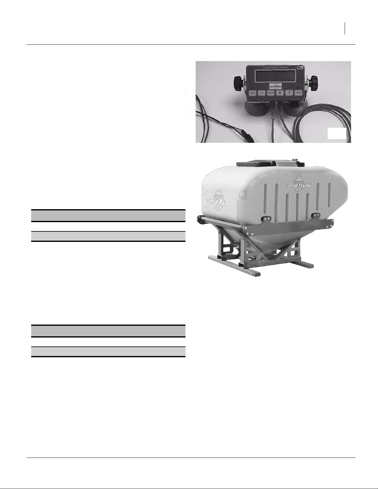
Great Plains Manufacturing, Inc. Options and Accessories 85
Veris Hydraulic Drive
The standard YP1225 and YP1625 include an elevated
contact wheel on the seed cart to drive the meter system. The optional Veris Drive replaces that with a
hydraulic pump and precision population controller.
For new planter purchases, consult your Great Plains
dealer for order codes.
For operations, see:
“Hydraulic Drive Operating Instructions” on page 94.
19977
82bu or 150 bu Seed Hopper
A hopper may be purchased with the Yield Pro Planter or
added later.
Note: The 150 bu hopper is incompatible with the liquid
fertilizer tank system, as it occupies the space used
for the tanks.
Option Packages Part Number
82bu Bulk Hopper (shown) 403-143K
150bu Bulk Hopper 403-174K
The hoppers have no other prerequisites on the planter,
but you will need a means of top-loading seed when the
hopper is mounted on the seed box. Consider ordering
the Auxiliary Hydraulic kit to power an auger.
The 82bu hopper is usually, and the 150bu hopper is
almost always, too heavy too be safely fork-lifted onto the
planter if already pre-loaded with seed.
For operations, see:
“Changing the Seed Box or Hopper” on page 23.
Seed Lubricants
Lubricant Part Number
Graphite (1 pound bottle) 821-042C
Talc (5 gallon container) 821-048C
25296
07/09/2009 401-226M
Page 90

86 YP1225 and 1625 Great Plains Manufacturing, Inc.
Auxiliary Hydraulic kit
When the planter is not in motion, these kits enable the
marker hydraulic circuit to be used to drive off-planter
equipment, such as a seed auger.
Option Packages Part Number
YP1225 Auxiliary Hydraulic Kit 401-435A
YP1625 Auxiliary Hydraulic Kit 407-441A
For operation, see “Using Auxiliary Hydraulic Circuit”
on page 24.
25323
Smart Box Mounting Kit
These kits support the mounting of AMVAC Smartbox®
containers and meters above row units. Smartbox is a
delivery system for pelletized seed/row treatments.
Planter Model Part Number
YP1225-1230 403-196A
YP1225-16TR -
YP1225-1820 403-197A
YP1225-2315 403-196A
YP1225-24TR 403-198A
YP1625-1630 403-199A
YP1625-2420 403-200A
YP1625-24TR -
YP1625-3115 403-201A
YP1625-32TR 403-201A
YP2425-2430 403-218A
YP2425-3620 403-219A
YP2425-4715 403-218A
YP2425-48TR 403-220A
24169
401-226M 07/09/2009
Page 91
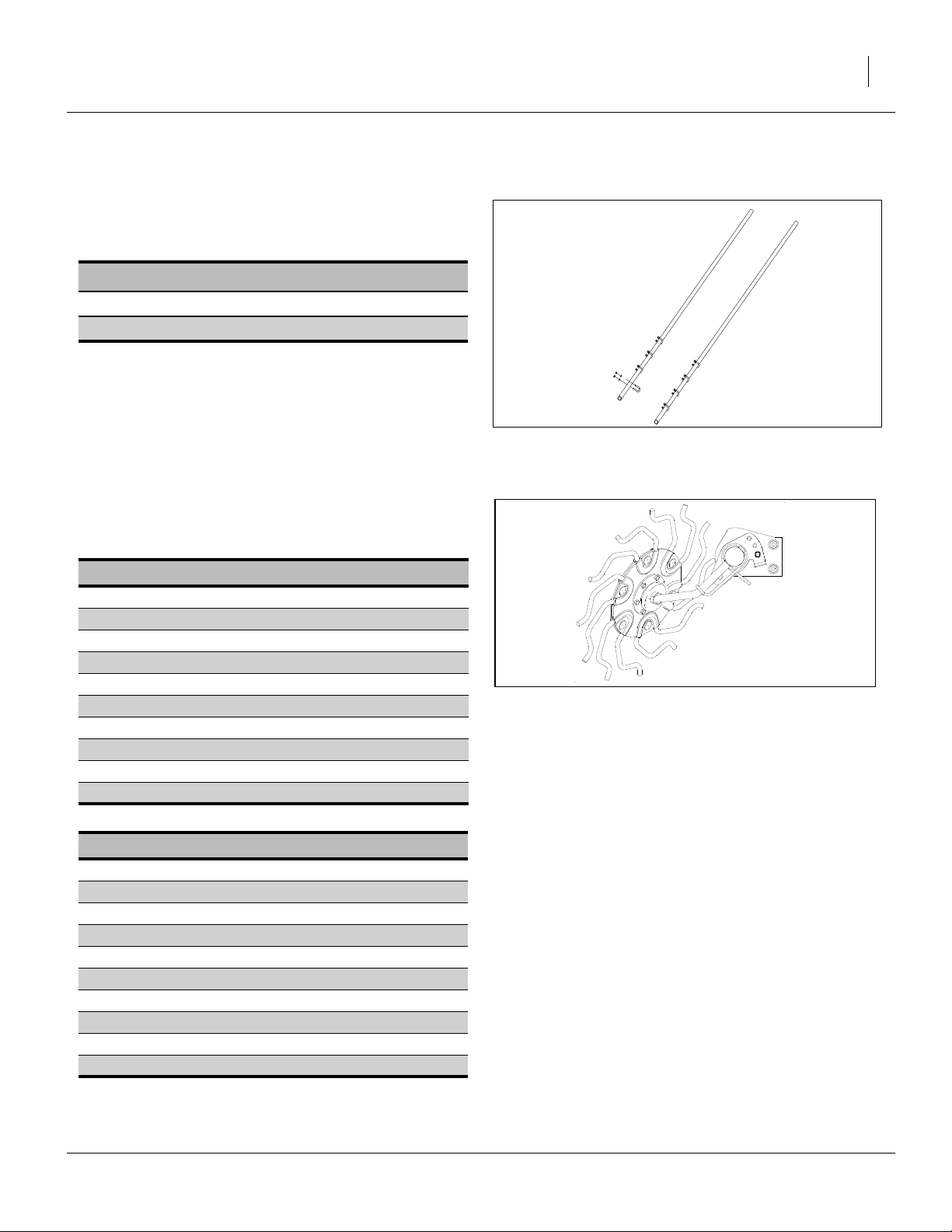
Great Plains Manufacturing, Inc. Options and Accessories 87
Row Options, Frame-Mounted
Underframe Attachment Kit
Frame-mounted options require this kit, which is not
standard on YP planters.
Underframe Kits Part Number
YP1225 204-515L
YP1625 204-496L
Terra-Tines
Stand-Alone Terra Tines
These row cleaners are available as frame-mounted,
either stand-alone (attached to underframe attachment
kits), or attached to frame-mounted coulters.
Stand-Alone Packages Part Number
YP1225-24TR (30in, double) 207-132A
YP1225-16TR (36in, double) 207-204A
YP1225-1230 (30in, single) 207-138A
YP1225-1820 (20in, single) 207-136A
YP1225-2315 (15in on 30in rows) 207-134A
YP1625-32TR (30in, double) 207-131A
YP1625-24TR (36in, double) 207-132A
YP1625-1630 (30in, single) 207-137A
YP1625-2420 (20in, single) 207-135A
YP1625-3115 (15in, single) 207-133A
Coulter-Mounted Terra Tines
Coulter-Mounted Packages Part Number
YP1225-24TR -
YP1225-16TR YP1225-1230 (30in) 207-592A
YP1225-1820 (20in) 207-584A
YP1225-2315 (15in) 207-576A
YP1625-32TR (30in) YP1625-24TR (36in) -
YP1625-1630 (30in) 207-591A
YP1625-2420 (20in) 207-583A
YP1625-3115 (15in) 207-575A
For operations, See “Unit-Mount Cleaner Adjust-
ments” on page 50
25322
25322
18400
07/09/2009 401-226M
Page 92

88 YP1225 and 1625 Great Plains Manufacturing, Inc.
Frame-Mounted (Zone) Coulters
Vantage I Coulters
These frame-mounted coulters may be used ahead of or
between row-unit coulters, with or without the Vantage I
fertilizer applicator. Use with Vantage I requires at least
the Fertilizer Manifold.
Frame-Mounted Coulter Only
YP1225 15in Blade Packages Part No.
YP1225-1230 (every row, fluted) 204-586A
YP1225-1230 (every row, turbo) 204-588A
YP1225-1820 (every row, fluted) 204-578A
YP1225-1820 (every row, turbo) 204-580A
YP1225-2315 (every row, fluted) 204-566A
YP1225-2315 (every row, turbo) 204-568A
YP1225-2315 (30in rows, fluted) 204-570A
YP1225-2315 (30in rows, turbo) 204-572A
22951
YP1625 15in Blade Packages Part No.
YP1625-1630 (every row, fluted) 204-585A
YP1625-1630 (30in rows, turbo) 204-587A
YP1625-2420 (every row, fluted) 204-577A
YP1625-2420 (30in rows, turbo) 204-579A
YP1625-3115 (every row, fluted) 204-565A
YP1625-3115 (30in rows, turbo) 204-567A
Frame-Mounted Vantage I Coulter
YP1225 17in Blade Packages Part No.
YP1225-24TR (between rows) 204-628A
YP1225-16TR (between rows) 204-092A
YP1225-1230 (every row) 204-590A
YP1225-1820 (every row) 204-582A
YP1225-2315 (30in rows) 204-574A
YP1625 17in Blade Packages Part No.
YP1625-32TR (between rows) 204-625A
YP1625-24TR (between rows) 204-628A
YP1625-1630 (every row) 204-589A
YP1625-2420 (every row) 204-581A
YP1625-3115 (30in rows) 204-573A
401-226M 07/09/2009
Page 93

Great Plains Manufacturing, Inc. Options and Accessories 89
Row Options (Unit-Mount)
Unit-Mounted Row Cleaners
Optional Martin row cleaners are unit-mount as:
• UMRC “stand-alone”, via unit-mount assembly , or;
• UMC-RC via coulter disk mounting bracket , with or
without a coulter disk).
These bundles include a manual.
1
2
Single-Wheel, Coulter-Mount Part Number
YP1225-24TR (30in) 207-108A
YP1225-16TR (36in) 207-125A
YP1625-32TR (30in) 207-107A
YP1625-24TR (36in) 207-108A
Double-Wheel, Coulter-Mount Part Number
YP1225 (30in) 207-126A
YP1225 (20in) 207-120A
YP1225 (15in) 207-114A
YP1625 (30in) 207-113A
YP1625 (15in on 30in rows) 207-113A
YP1625 (20in) 207-119A
Single-Wheel, Stand-Alone Part Number
YP1225-24TR (30in) 207-112A
YP1225-16TR (36in) 207-129A
YP1625-32TR (30in) 207-111A
YP1625-24TR (36in) 207-112A
1
2
Note: Single-Row planters support single- or double-
wheel unit-mounted row cleaners.
Note: Twin-Row planters support only single-wheel unit-
mounted row cleaners, in alternating left/right
cleaner hub orientations.
These kits do not include a manual.
Separately order one 204-085M-A if ordering kits.
Individual Row Cleaners Part Number
UMRC Dual Wheel 207-213K
UMRC LH Single Wheel 207-215K
UMRC RH Single Wheel 207-216K
UMC-RC Dual Wheel 207-098S
UMC-RC LH Single Wheel 207-092S
UMC-RC RH Single Wheel 207-093S
RC Install/Use/Parts Manual 204-085M-A
27345
Double-Wheel, Stand-Alone Part Number
YP1225 (30in) 207-130A
YP1225 (20in) 207-124A
YP1225 (15in) 207-118A
YP1625 (30in) 207-129A
YP1625 (20in) 207-123A
YP1625 (15in on 30in rows) 207-117A
For operations, see:
See “Unit-Mount Cleaner Adjustments” on page 50.
07/09/2009 401-226M
Page 94

90 YP1225 and 1625 Great Plains Manufacturing, Inc.
Unit-Mounted Disk Coulters
Optional unit-mount disk coulters are available with 15in
fluted blades, 15in turbo blades or 14in straight blades. If
you need complete coulters, with unit mount and blade,
the selection includes:
15in Fluted Packages Part Number
YP1225-24TR (30in) 204-528A
YP1225-16TR (36in) 204-551A
YP1225-1230 (30in) 204-552A
YP1225-1820 (20in) 204-546A
YP1225-2315 (15in, every row) 204-534A
YP1225-2315 (15in on 30in rows) 204-540A
YP1625-32TR (30in) 204-527A
YP1625-24TR (36in) 204-545A
YP1625-1630 (30in) 204-551A
YP1625-2420 (20in) 204-545A
YP1625-3115 (15in, every row) 204-533A
YP1625-3115 (15in, 30in rows) 204-539A
22817
15in Turbo Packages Part Number
YP1225-24TR (30in) 204-530A
YP1225-16TR (36in) 204-553A
YP1225-1230 (30in) 204-554A
YP1225-1820 (20in) 204-548A
YP1225-2315 (15in, every row) 204-536A
YP1225-2315 (15in on 30in rows) 204-542A
YP1625-32TR (30in) 204-529A
YP1625-24TR (36in) 204-547A
YP1625-1630 (30in) 204-553A
YP1625-2420 (20in) 204-547A
YP1625-3115 (15in, every row) 204-535A
YP1625-3115 (15in, 30in rows) 204-541A
14in Straight Packages Part Number
YP1225-24TR (30in) 204-532A
YP1225-16TR (36in) 204-555A
YP1225-1230 (30in) 204-556A
YP1225-1820 (20in) 204-550A
YP1225-2315 (15in on 30in rows) 204-544A
YP1625-32TR (30in) 204-531A
YP1625-24TR (36in) 204-549A
YP1625-1630 (30in) 204-555A
YP1625-2420 (20in) 204-549A
YP1625-3115 (15in, 30in rows) 204-543A
401-226M 07/09/2009
Page 95

Great Plains Manufacturing, Inc. Options and Accessories 91
Coulter Blades
Replacement and alternate coulter blades include (qty. 1
per row unit):
15in Turbo Packages Part Number
Turbo, 15in (20 flutes) 820-327C
Fluted, 15in (50 flutes) 820-331C
Straight, 14in 820-259C
For operations, see:
25299
“Unit-Mounted Coulter Adjustments” on page 51.
Gauge Wheel Scrapers
When planting in moist or sticky soils, these scrapers are
useful in preventing build-up that might otherwise result
in shallow planting.
Order one part per wheel (2 per opener).
Wheel Scrapers Part Number
1
2
⁄
in Gauge wheel scraper
2
3in Gauge wheel scraper 404-195D
4in Gauge wheel scraper 404-196D
404-194D
The scrapers mount on the bottom rear of the depth
wheel arm, using the existing bolt and lock washer. The
slot in the scraper is long enough to clear the lower
grease zerk, and allow adjustment as wheel and scraper
wear.
For operations, see:
“Adjusting Gauge Wheel Scrapers” on page 53.
Seed Meters
Seed meters are not standard in the base Yield Pro
Planter configuration. Normally, one or more sets are
ordered with the original planter. One set is factoryinstalled.
Meters are simple to change. Available models include
(part number are for a single row unit; each Singulator
Plus includes one seed wheel):
Meters Part Number
Singulator Plus 403-156K
12FP 12-Finger Pick-Up (30in) 403-158K
12FP 12-Finger Pick-Up (sunflower) 403-203K
6FP 6-Finger Pick-Up (Twin/20in) 403-169K
For operations, see:
“Finger Meter Adjustments” on page 59.
25298
25294
07/09/2009 401-226M
Page 96

92 YP1225 and 1625 Great Plains Manufacturing, Inc.
Seed Meter Wheels
Singulator Plus meters accept a variety of seed wheels,
each optimized for specific seeds. Wheels are simple to
change. 25 Series meters accept only green seed
wheels. Choices include:
Meter Wheels Part Number
Soybean (1700-2000 seeds/lb) 403-122D
Soybean (2000-2700 seeds/lb) 403-123D
Soybean (2700-3200 seeds/lb) 403-124D
Soybean (3200-3600 seeds/lb) 403-125D
Soybean (3600-4000 seeds/lb) 403-126D
Cotton (4000-4600 seeds/lb) 403-133D
Cotton (4600-5200 seeds/lb) 403-134D
Cotton (5200-6000 seeds/lb) 403-135D
Milo (low rate/solid, 51 pockets) 403-136D
Milo (low rate/row, 102 pockets) 403-137D
Milo (high rate/solid, 135 pockets,
10,500-14,000 seeds/lb)
Milo (high rate/solid, 135 pockets)
12,000-18,000 seeds/lb)
Milo (high rate/row, 135 pockets,
10,500-14,000 seeds/lb)
Milo (high rate/row, 135 pockets)
12,000-18,000 seeds/lb)
403-138D
403-140D
403-139D
403-141D
Seed-Lok® Seed Firmer
The base Yield Pro Planter includes no seed firmers. A
choice of firmers is an option in the product bundles, or
may be field-installed as kits. Only one type of seed
firmer may be installed at the same time.
The Seed-Lok® seed firmer also supports low-rate fertilizer delivery. For this use, the optional fertilizer system
(page 85) must also be installed.
25295
Meters Part Number
25 Series Seed-Lok® kit
(per opener)
404-093K
For operations, see:
“Seed Firmer Adjustments” on page 61.
401-226M 07/09/2009
25293
Page 97

Great Plains Manufacturing, Inc. Options and Accessories 93
Keeton Seed Firmer
The base Yield Pro Planter includes no seed firmers. A
choice of firmers is an option in the product bundles, or
may be field-installed as kits. Only one type of seed
firmer may be installed at the same time.
Meters Part Number
Keeton seed firmer (per opener) 890-796C
Keeton seed firmer (per opener) 890-840C
The Keeton seed firmer also supports low-rate fertilizer
delivery. For this use, the optional fertilizer system
(page 83) must also be installed.
For operations, see:
“Seed Firmer Adjustments” on page 61.
Row Unit Press Wheels
The base Yield Pro planter includes a choice of press
wheels. Additional wheels are available, and all may be
field-installed.
This manual does not list kit part numbers as the available wheels are often region-specific. Consult your Great
Plains dealer.
For operations, see:
“Press Wheels” on page 62.
20327
27293
07/09/2009 401-226M
Page 98

94 YP1225 and 1625 Great Plains Manufacturing, Inc.
Hydraulic Drive Operating Instructions
Drive Operational Requirements
Hydraulic System:
Closed Center, pressure compensated or load sensed
systems only
IMPORTANT !
Drive will not operate on Open-Center hydraulic systems
Minimum Hyd. Pressure 2250 psi
Maximum Hyd. Pressure 3000 psi
Maximum Required Flow 13 gpm
Electrical System:
Voltage 12 volt DC
Current 4 amperes
Tractor Hookup
Hydraulics:
1. Connect pressure hose (P) to retraction outlet
2. Connect motor return hose (T) to motor return port (if
available) or to extension outlet.
3. Set flow rate at maximum required flow of 13 gpm.
4. If tractor is equipped with electro-hydraulic valves,
set timer to “constant” flow.
Electrical:
Refer to Figure 97
Power must be connected directly to the battery. Make
sure that eyelets are properly connected (red to positive,
black to negative). Connect female socket to power port
adapter.
22715
Figure 97
Veris Electrical Connection
401-226M 07/09/2009
22714
Page 99

Great Plains Manufacturing, Inc. Hydraulic Drive Operating Instructions 95
Controller Menu
ON / VR
set= * spd=
PRESET RATES
PRESET
selected
PRESET 1
*
PRESET 2
*
PRESET 3
*
FUNCTION
FUNCTION
FUNCTION
FUNCTION
SPEED CAL IBRATION
UP:CALIBRATE
DN:RESTORE
CAL SETTINGS
*
FUNCTION
PRESS ENGAGE
AT 1 ST FL A G
ENGAGE
___ft ENGAGE AT
2ND FLAG
ENGAGE
DISTANCE ERROR
____%
FUNCTION
UP:CALCULATE NEW
DN:KEEP CURRENT
KEY
set = * spd=
out = ______ _. _
FUNCTION ENGAGE
ON / VR
- cab console LCD screen
- Condition for progressing to next screen
* Adjust number up/down or toggle between selections using
the
** Refer to the troubleshooting section of the manual for a
description of error messages.
keys.
out= ______ _._
FUNCTION
CALIBRATION
NUMBER *
FUNCTION
recipe format
*
VERIS V1
selected
FUNCTION
manual/preset
*
MANUAL
selected
FUNCTION
PRESS UP KEY TO
CALIBRATE RATE
FUNCTION
PRESS UP KEY TO
CALIBRATE SPEED
FUNCTION
- Keys on cab console
VARIABLE RATE
FUNCTION
RAWSON NOMINAL
*
RAWSON
selected
FUNCTION
FUNCTION
invalid
time
**
ENGAGE
FUNCTION:EXIT
FUNCTION
RATE CALIBRATION
CAL SETTINGS
*
CAL SETTINGS
WIDTH *
CAL SETTINGS
# ROWS *
CAL SETTINGS
SPEED *
ENTER TARGET
AMOUNT *
FUNCTION
FUNCTION
calibration
error
**
valid
time
TIME TO RUN FOR
CAL ___s
CLEAR DRIVE AREA
UP:CLEAR DN:EXIT
ENGAGE:RUN DRIVE
FUNCT:EXIT
___s out= ______
ENGAGE TO STOP
ENTER AMOUNT
COLLECTED *
NEW CAL #: ____
OLD CAL #: ____
UP:KEEP NEW
DN:KEEP OLD
FUNCTION
FUNCTION
FUNCTION
FUNCTION
FUNCTION
FUNCTION
ENGAGE
calibration
successful
FUNCTION
FUNCTION
23251
07/09/2009 401-226M
Page 100

96 YP1225 and 1625 Great Plains Manufacturing, Inc.
Console Functions
Refer to Figure 98
The use of each key is as follows:
• On/VR key-turns drive system on. Press twice for VR
mode. Note: Engage key must also be pressed to start
drive operation.
• Off key: used to shut off Console.
• Function key: used in calibration mode and to program
Console for VR recipes.
• Up/down arrow keys: used to change rates manually,
to set calibration numbers, and VR controller options.
• Engage key: press to start drive.
Note: Drive will not run unless light above key is illuminat-
ed.
Note: Figure 98 shows Main Operating Screen in manual
mode.
Figure 98
Veris Key Functions
22710
Calibration
Refer to Figure 99
1. Turn on Controller Console by pressing On/VR key.
Green light above On/VR key will illuminate when
power is on. Adjust desired planting rate by using the
Up/Down arrow keys to change the Set rate.
2. Set the desired Rate by using the Up/Down arrow
keys.
Refer to Figure 100
3. Press Function key until Calibration Number window
appears.
4. Select drive calibration number based on row spacing and metering wheel, from chart. See “Planting
Calibration” on page 105.
5. Use Up/Down arrow keys to set Calibration number.
Figure 99
Initiate Calibration
Figure 100
Calibration Number Prompt
22715
22778
401-226M 07/09/2009
 Loading...