

Operator’s Manual
Yield-Pro® Planter
Manufacturing, Inc.
www.greatplainsmfg.com
Read the operator manual entirely. When you see this symbol, the subsequent
instructions and warnings are serious - follow without exception. Your life and
!
the lives of others depend on it!
YP1220
27454
Illustrations may show optional equipment not supplied with standard unit
FigureSpacer:
EN
© Copyright 2012 Printed 03/14/2012 401-506M

Blank page for proper duplexing.

Great Plains Manufacturing, Inc.
Table of Contents
Important Safety Information ....................................1
Introduction ..............................................................10
Description of Unit ......................................................10
Document Family .......................................................10
Intended Usage ......................................................10
Covered Models .........................................................10
Using This Manual......................................................10
Definitions...............................................................10
Owner Assistance ......................................................11
Product Support .....................................................11
Preparation and Setup .............................................12
Pre-Start Checklist .....................................................12
Hydraulic Hose Hookup .............................................13
Protecting Hydraulic Motor Seals ...............................14
Hitching Tractor to Planter..........................................15
3-Point Hitch...........................................................15
Hydraulic Tongue Hitch ..........................................15
Tongue Height........................................................16
Hydraulic Charge and Bleed ......................................17
Lift Hydraulics.........................................................17
Cylinder Hydraulics.................................................17
Leveling Frame Side-to-Side......................................17
Wing Alignment ..........................................................19
Marker Extension .......................................................19
Optional Monitor Mounting Plate ................................20
Operating Instructions.............................................21
Pre-Start Checklist .....................................................21
Folding the Planter .....................................................22
Unfolding the Planter..................................................24
Changing the Seed Box or Hopper ............................25
Using Auxiliary Hydraulic Circuit.............................26
Pre-Usage Checklist...................................................26
Transporting ...............................................................28
Field Operation...........................................................29
Seed Hopper Sensor..............................................29
Monitor Operation...................................................30
Electric Clutch Operation............................................30
Electric Clutch Lockup............................................31
Marker Operation .......................................................32
Re-phasing Lift System ..........................................32
Re-phasing Fold System ........................................32
Airbox Operation ........................................................ 33
Fan Operation ........................................................ 33
Y-Tubes.................................................................. 33
Airbox Troubleshooting .......................................... 34
Parking....................................................................... 35
3 Point Hitch........................................................... 35
Storage ...................................................................... 36
Adjustments ............................................................. 37
Planting Rate ............................................................. 38
Drive Speed Range Sprockets............................... 38
Transmission Sprockets......................................... 38
Contact Wheel Drive .............................................. 39
Checking Singulated Rate ......................................... 40
Seed Rate Check Example ................................ 40
Checking Singulated Rate...................................... 40
Marker Adjustments ................................................... 41
Dual Marker Speed Adjustment ............................. 41
Adjusting Marker Extension ...................................41
Marker Disk Adjustment ......................................... 42
Fan Adjustments ........................................................ 42
20 Series Row-Unit Adjustments ............................... 43
Row-Unit Down Pressure....................................... 44
Row-Unit Planting Depth........................................ 44
Side Gauge Wheel Adjustments ............................ 45
Meter Wheel Replacement..................................... 46
Seed Firmer Adjustments....................................... 47
Keeton Seed Firmer Adjustment ........................ 47
Seed-Lok™ Seed Firmer Lock-Up ..................... 48
Press Wheels ......................................................... 48
Troubleshooting....................................................... 50
Maintenance and Lubrication ................................. 54
Maintenance .............................................................. 54
Bleeding Hydraulics ................................................... 55
Bleeding Lift Hydraulics.......................................... 55
Bleeding Fold Cylinder Hydraulics ......................... 55
Bleeding Marker Hydraulics ................................... 55
Meter Maintenance .................................................... 56
Cleaning Out Meters .............................................. 56
Meter Slide Maintenance .......................................57
Replacing Meter Slide ........................................ 58
Installing Flow Gate............................................ 58
© Copyright 2005, 2006, 2007, 2008, 2011, 2012. All rights Reserved.
Great Plains Manufacturing, Inc. providesthis publication “as is” without warranty of any kind, either expressed or implied. While every precaution has been taken in the preparation
of this manual, Great Plains Manufacturing, Inc. assumes no responsibility for errors or omissions. Neither is any liability assumed for damages resulting from the use of the information contained herein. Great Plains Manufacturing, Inc. reserves the right to revise and improve its products as it sees fit. This publication describes the state of this product at
the time of its publication, and may not reflect the product in the future.
The following are trademarks of Great Plains Mfg., Inc.: Application Systems, Ausherman, Land Pride, Great Plains
All other brands and product names are trademarks or registered trademarks of their respective holders.
03/14/2012 401-506M
Great Plains Manufacturing, Incorporated Trademarks
Printed in the United States of America.

YP1220 Great Plains Manufacturing, Inc.
Cleaning Out Air System............................................ 59
Chain Maintenance .................................................... 60
Chain Slack............................................................ 60
Row Unit Chain Tension ........................................60
Disk Spreaders .......................................................... 61
Row-Unit Side Wheels ............................................... 62
Seed Flap Replacement ............................................ 62
Marker Maintenance .................................................. 63
Lubrication ................................................................. 64
Seed Lubricants ..................................................... 69
Options and Accessories........................................ 70
Hydraulic Tongue....................................................... 70
Markers ...................................................................... 70
Auxiliary Hydraulic kit................................................. 70
82bu or 150 bu Seed Hopper..................................... 71
Seed Lubricants ..................................................... 71
18.4R42 Tires ............................................................ 71
Row Options (Unit-Mount) ......................................... 72
Volumetric Wheels............................................. 72
Seed Meters .......................................................... 72
20 Series Seed Meter Wheels ............................... 72
Singulating Wheels ............................................ 72
Seed-Lok® Seed Firmer........................................ 73
Keeton Seed Firmer............................................... 73
Row Unit Press Wheels ......................................... 73
Appendix .................................................................. 74
Specifications and Capacities.................................... 74
Tire Inflation............................................................... 74
Torque Values Chart ................................................. 75
Hydraulic System Diagram ........................................ 76
Chain Routing............................................................ 77
Ground Drive ......................................................... 77
Wing Drive ............................................................. 78
20 Series Meter Drive Chain.................................. 79
Warranty .................................................................... 80
Index ......................................................................... 81
401-506M 03/14/2012
Great Plains Manufacturing, Inc. 1
Important Safety Information
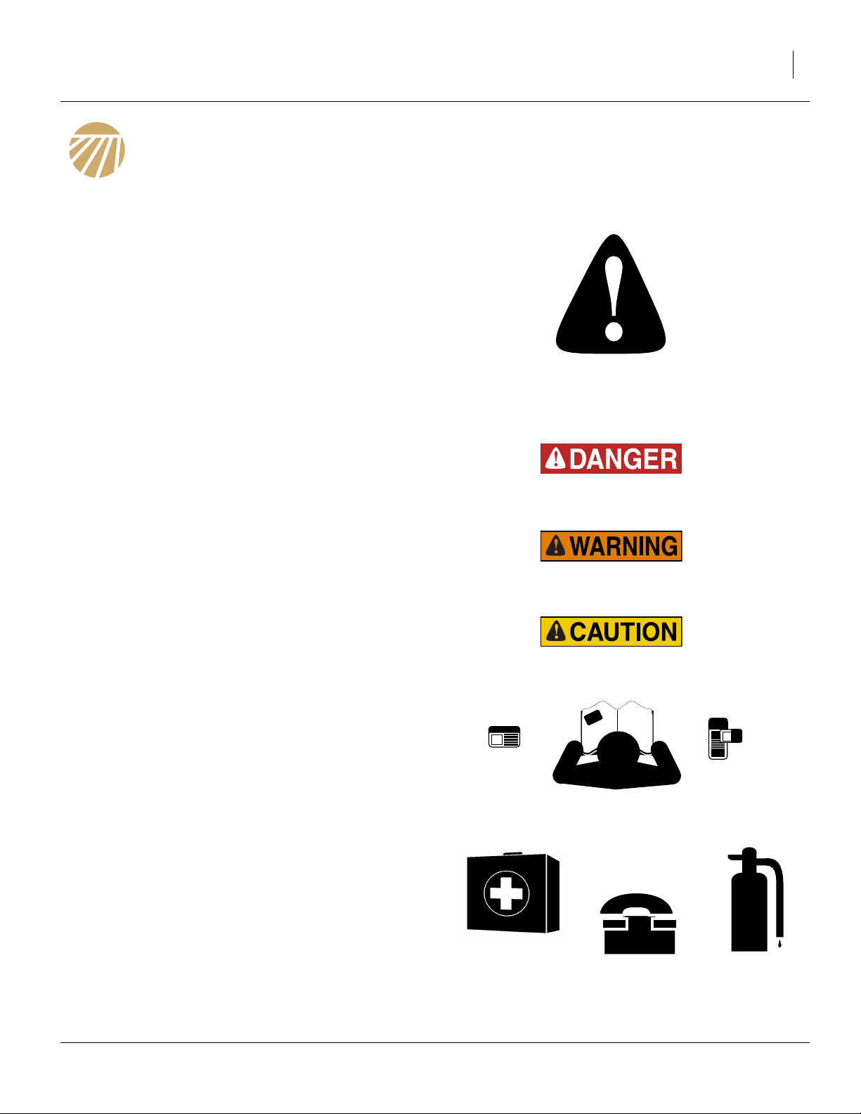
Look for Safety Symbol
The SAFETY ALERT SYMBOL indicates there is a
potential hazard to personal safety involved and extra
safety precaution must be taken. When you see this
symbol, be alert and carefully read the message that follows it. In addition to design and configuration of equipment, hazard control and accident prevention are
dependent upon the awareness, concern, prudence and
proper training of personnel involved in the operation,
transport, maintenance and storage of equipment.
Be Aware of Signal Words
Signal words designate a degree or level of hazard seriousness.
DANGER indicates an imminently hazardous situation
which, if not avoided, will result in death or serious injury.
This signal word is limited to the most extreme situations,
typically for machine components that, for functional purposes, cannot be guarded.
WARNING indicates a potentially hazardous situation
which, if not avoided, could result in death or serious
injury, and includes hazards that are exposed when
guards are removed. It may also be used to alert against
unsafe practices.
CAUTION indicates a potentially hazardous situation
which, if not avoided, may result in minor or moderate
injury. It may also be used to alert against unsafe practices.
Be Familiar with Safety Decals
▲ Read and understand “Safety Decals” on page 6, thor-
oughly.
▲ Read all instructions noted on the decals.
▲ Keep decals clean. Replace damaged, faded and illegible
decals.
Prepare for Emergencies
▲ Be prepared if a fire starts
▲ Keep a first aid kit and fire extinguisher handy.
▲ Keep emergency numbers for doctor, ambulance, hospital
and fire department near phone.
03/14/2012 401-506M
911

2 YP1220 Great Plains Manufacturing, Inc.
Wear Protective Equipment
▲ Wear protective clothing and equipment.
▲ Wear clothing and equipment appropriate for the job. Avoid
loose-fitting clothing.
▲ Because prolonged exposure to loud noise can cause hear-
ing impairment or hearing loss, wear suitable hearing protection such as earmuffs or earplugs.
▲ Because operating equipment safely requires your full
attention, avoid wearing entertainment headphones while
operating machinery.
Avoid High Pressure Fluids
Escaping fluid under pressure can penetrate the skin,
causing serious injury.
▲ Avoid the hazard by relieving pressure before disconnecting
hydraulic lines.
▲ Use a piece of paper or cardboard, NOT BODY PARTS, to
check for suspected leaks.
▲ Wear protective gloves and safety glasses or goggles when
working with hydraulic systems.
▲ If an accident occurs, seek immediate medical assistance
from a physician familiar with this type of injury.
Handle Chemicals Properly
Agricultural chemicals, including treated seed, can be
dangerous. Improper use can seriously injure persons,
animals, plants, soil and property.
▲ Read and follow seed supplier’s instructions.
▲ Wear protective clothing.
▲ Handle all treated seed with care.
▲ Avoid inhaling smoke from any type of chemical fire.
▲ Store or dispose of unused treated seed as specified by
chemical manufacturer.
Keep Riders Off Machinery
Riders obstruct the operator’s view. Riders could be
struck by foreign objects or thrown from the machine.
▲ Never allow children to operate equipment.
▲ Keep all bystanders away from machine during operation.
401-506M 03/14/2012
Great Plains Manufacturing, Inc. 3
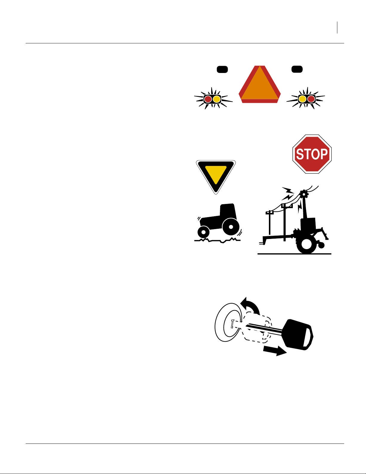
Use Safety Lights and Devices
Slow-moving tractors and towed implements can create
a hazard when driven on public roads. They are difficult
to see, especially at night.
▲ Use flashing warning lights and turn signals whenever driv-
ing on public roads.
Use lights and devices provided with implement
Transport Machinery Safely
Maximum transport speed for implement is 20 mph (32
kph). Some rough terrains require a slower speed. Sudden braking can cause a towed load to swerve and
upset.
▲ Do not exceed 20 mph (32 kph). Never travel at a speed
which does not allow adequate control of steering and stopping. Reduce speed if towed load is not equipped with
brakes.
▲ Comply with state and local laws.
▲ Do not tow an implement that, when fully loaded, weighs
more than 1.5 times the weight of towing vehicle.
▲ Carry reflectors or flags to mark planter in case of break-
down on the road.
▲ Keep clear of overhead power lines and other obstructions
when transporting. Refer to transport dimensions under
“Specifications and Capacities” on page 74.
▲ Do not fold or unfold the planter while the tractor is mov-
ing.
Shutdown and Storage
▲ Lower planter, put tractor in park, turn off engine, and
remove the key.
▲ Secure planter using blocks and supports provided.
▲ Detach and store planter in an area where children nor-
mally do not play.
OFF
03/14/2012 401-506M
4 YP1220 Great Plains Manufacturing, Inc.
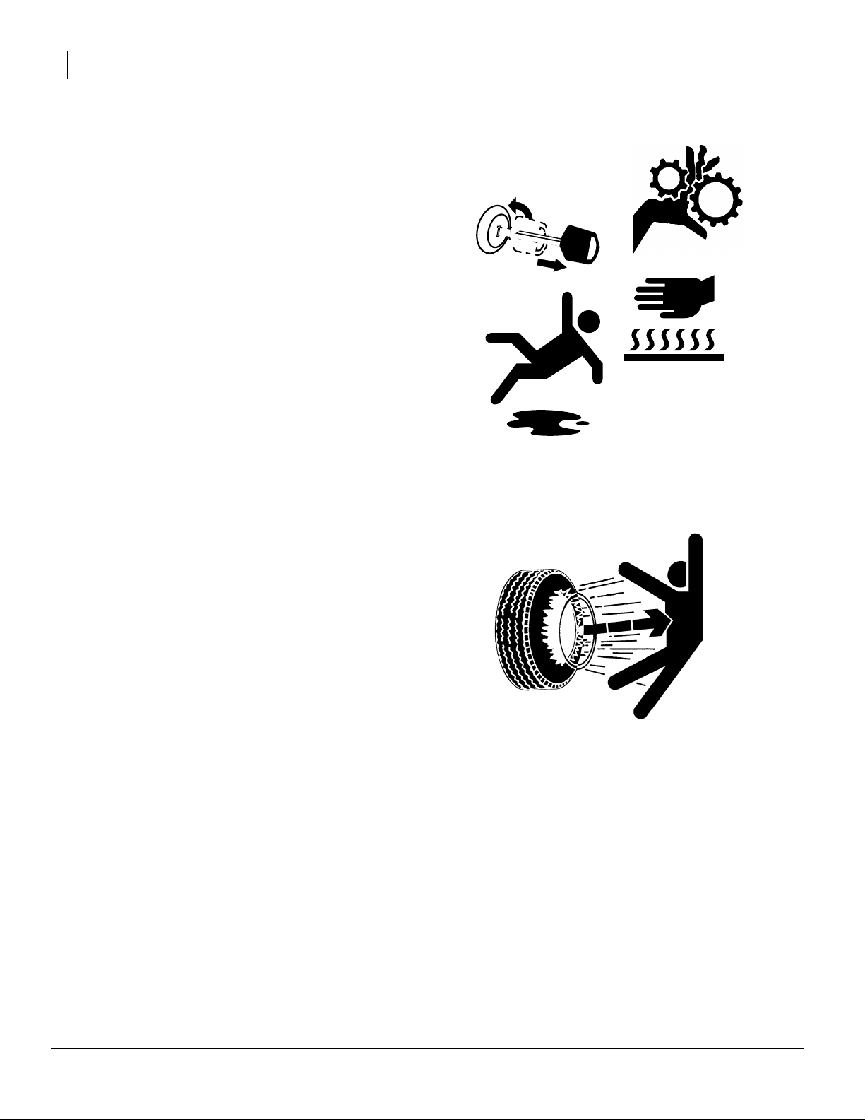
Practice Safe Maintenance
▲ Understand procedure before doing work. Use proper tools
and equipment. Refer to this manual for additional information.
▲ Work in a clean, dry area.
▲ Lower the planter, put tractor in park, turn off engine, and
remove key before performing maintenance.
▲ Make sure all moving parts have stopped and all system
pressure is relieved.
▲ Allow planter to cool completely.
▲ Disconnect battery ground cable (-) before servicing or
adjusting electrical systems or before welding on planter.
▲ Inspect all parts. Make sure parts are in good condition and
installed properly.
▲ Remove buildup of grease, oil or debris.
OFF
▲ Remove all tools and unused parts from planter before
operation.
Tire Safety
Tire changing can be dangerous and should be performed by trained personnel using correct tools and
equipment.
▲ When inflating tires, use a clip-on chuck and extension hose
long enough for you to stand to one side–not in front of or
over tire assembly. Use a safety cage if available.
▲ When removing and installing wheels, use wheel-handling
equipment adequate for weight involved.
401-506M 03/14/2012
Great Plains Manufacturing, Inc. 5
Safety At All Times
Thoroughly read and understand the instructions in this
manual before operation. Read all instructions noted on
the safety decals.
▲ Be familiar with all planter functions.
▲ Operate machinery from the driver’s seat only.
▲ Do not leave planter unattended with tractor engine run-
ning.
▲ Do not dismount a moving tractor. Dismounting a moving
tractor could cause serious injury or death.
▲ Do not stand between the tractor and planter during hitch-
ing.
▲ Keep hands, feet and clothing away from power-driven
parts.
▲ Wear snug-fitting clothing to avoid entanglement with mov-
ing parts.
▲ Watch out for wires, trees, etc., when folding and raising
planter. Make sure all persons are clear of working area.
03/14/2012 401-506M
6 YP1220 Great Plains Manufacturing, Inc.
Safety Decals
Safety Reflectors and Decals
Your implement comes equipped with all lights, safety
reflectors and decals in place. They were designed to
help you safely operate your implement.
▲ Read and follow decal directions.
▲ Keep lights in operating condition.
▲ Keep all safety decals clean and legible.
▲ Replace all damaged or missing decals. Order new decals
from your Great Plains dealer. Refer to this section for
proper decal placement.
▲ When ordering new parts or components, also request cor-
responding safety decals.
818-055C
To install new decals:
1. Clean the area on which the decal is to be placed.
2. Peel backing from decal. Press firmly on surface,
being careful not to cause air bubbles under decal.
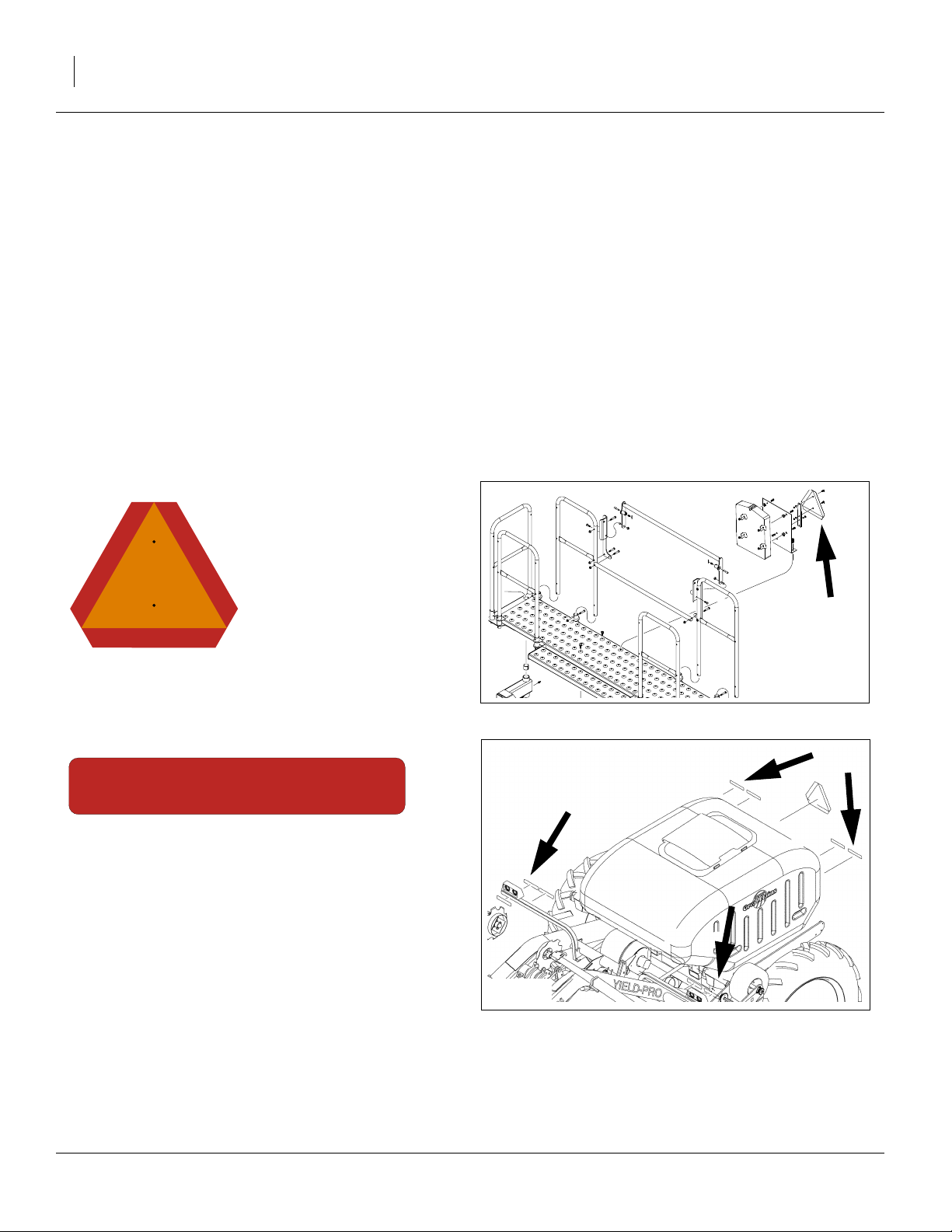
Slow Moving Vehicle Reflector
On the back of the planter;
one total
838-266C
Red Reflectors
On the back of walkboard each end,
and on the backside of each light mounting bar;
four total
23263
27375
401-506M 03/14/2012
Great Plains Manufacturing, Inc. 7
838-265C
Amber Reflectors
On the back of the wing toolbar outboard of drive mount,
outside front of the light brackets;
four total
27375
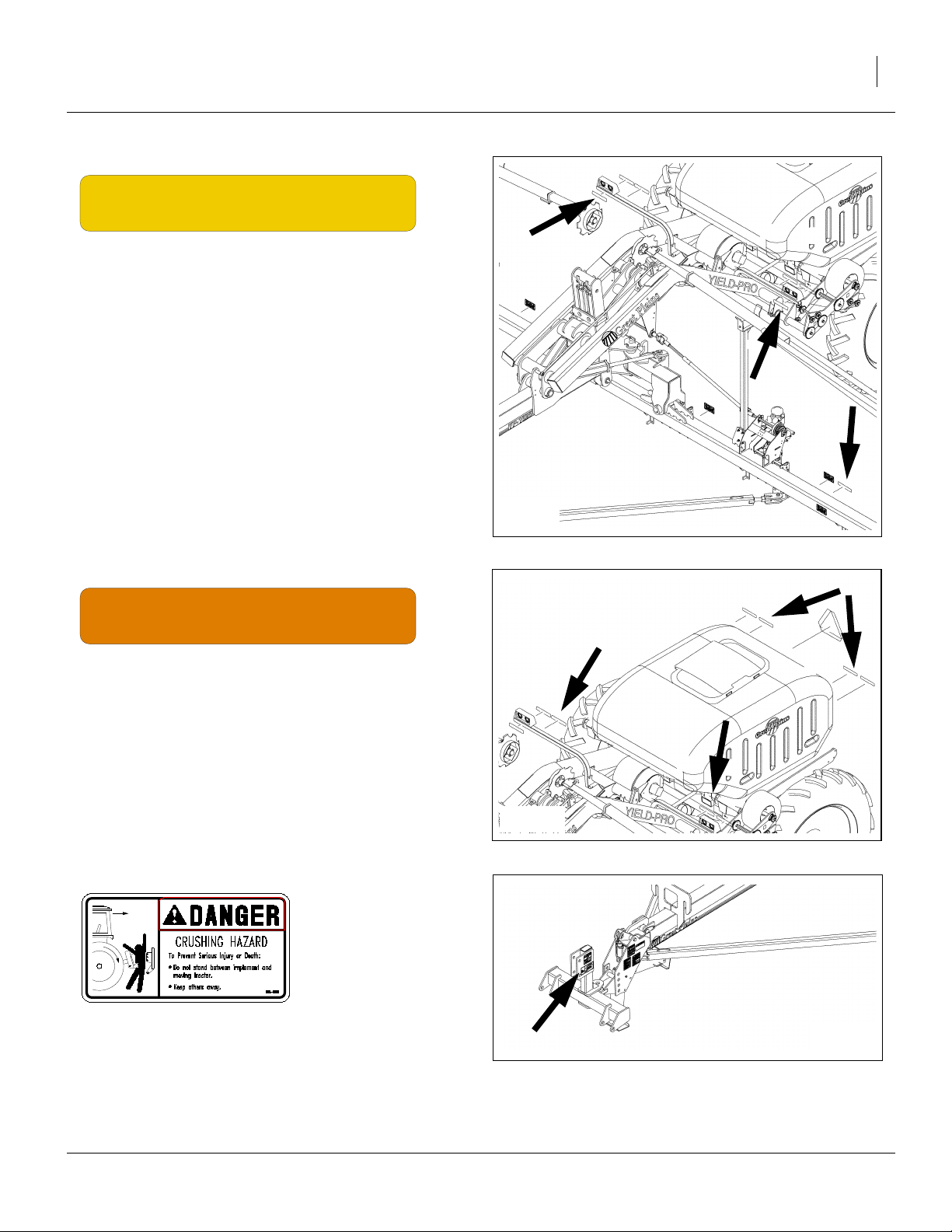
838-267C
Daytime Reflectors
On walkboard inside of red reflectors, and
on light mounting bar inside of red reflectors;
four total
818-590C
Danger: Crushing Hazard
On the 3-point hitch;
one total
27375
27375
03/14/2012 401-506M
8 YP1220 Great Plains Manufacturing, Inc.
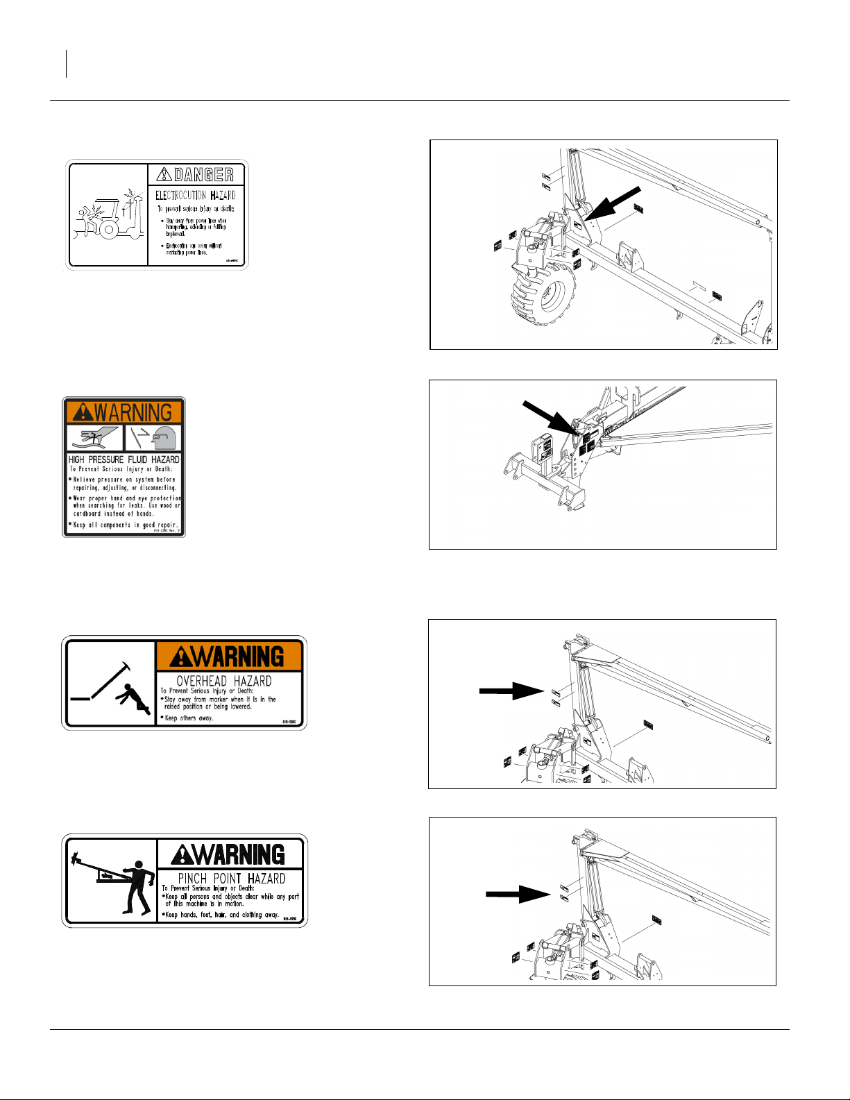
838-599C (Option)
Warning: Electrocution Hazard
On marker section each end;
two total
27375
818-339C
Warning: High Pressure Fluid Hazard
On the tongue;
one total
818-580C (Option)
Warning: Overhead Hazard
On marker section each end;
two total
818-579C (Option)
27375
27375
Warning: Pinch/Shear Hazard
On marker section each end;
two total
401-506M 03/14/2012
27375
Great Plains Manufacturing, Inc. 9
818-188C
WARNING
EXCESSIVE SPEED HAZARD
To Prevent Serious Injury or Death:
Do Not exceed 20 mph maximum transport
speed. Loss of vehicle control and/or machine
can result.
Warning: Excessive Speed
On the tongue;
one total
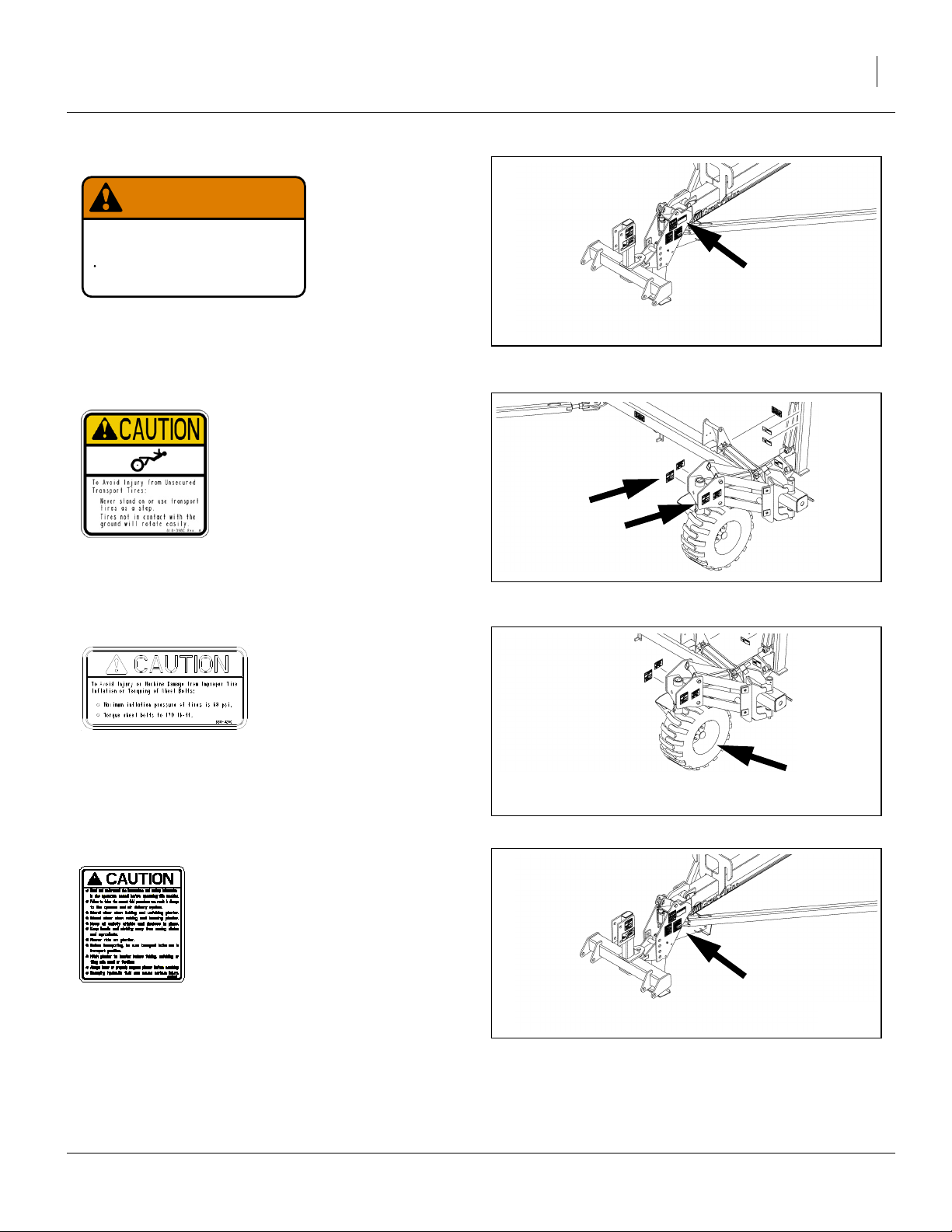
818-398C
818-188C Rev. C
27375
Caution: Tires Not A Step
Above both sides of both tires;
four total
838-426C
Caution: Tire Pressure 60 PSI
Inside valve stem rim of both gauge wheel tires;
two total
838-995C
Caution: Read Operator Manual
On the tongue;
one total
27375
27375
27375
03/14/2012 401-506M
10 YP1220 Great Plains Manufacturing, Inc.
Introduction
Great Plains welcomes you to its growing family of new
product owners. This planter has been designed with
care and built by skilled workers using quality materials.
Proper setup, maintenance, and safe operating practices
will help you get years of satisfactory use from the
machine.
Description of Unit
The 30-foot Row Yield-Pro® Planter is pull-type planting
implement for use in conventional till, minimum-till, or
light no-till conditions.
YP1220 Yield-Pro® Planters are outfitted with 20 Series,
side-depth-control row-units.The Planter folds for transport.
Document Family
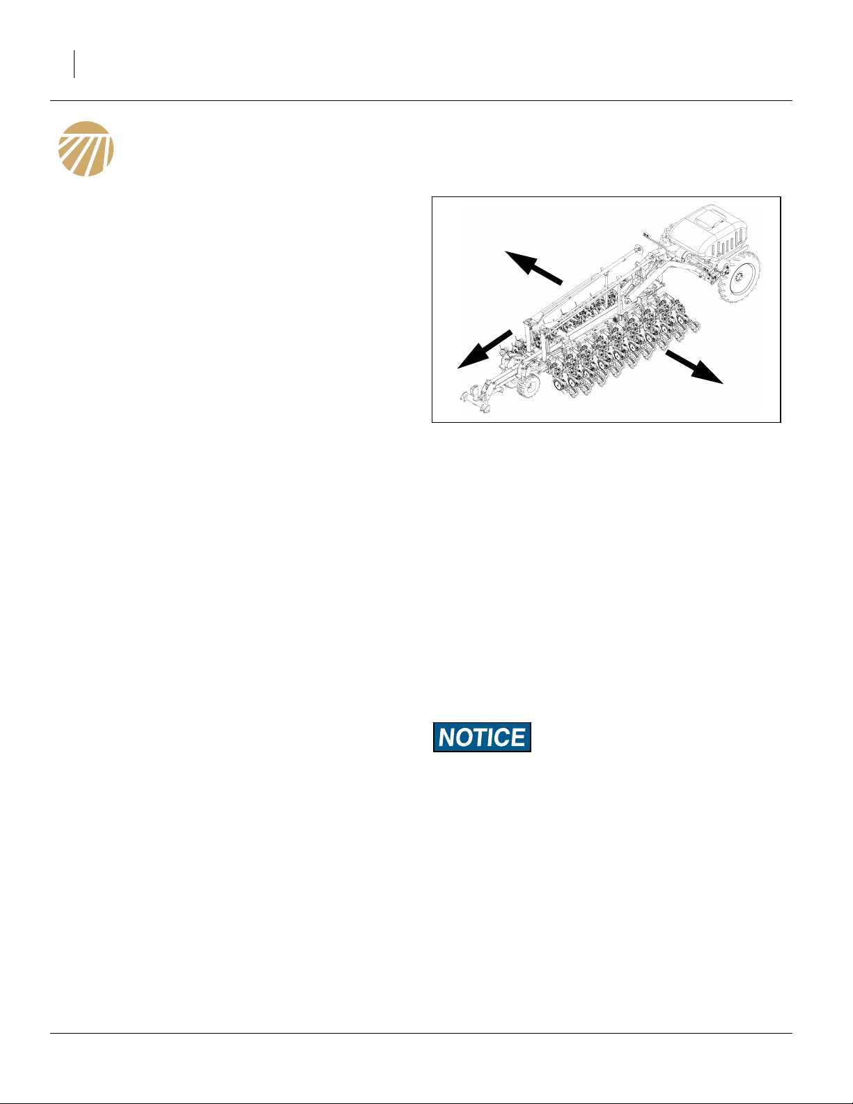
R
Figure 1
Left/Right Convention
L
27455
401-506M Operator Manual (this manual)
401-506B Seed Rate Manual
401-506P Parts Manual
Intended Usage
Use the planter to seed production-agriculture crops
only. Do not modify the planter for use with attachments
other than Great Plains options and accessories specified for use with the planter.
Covered Models
YP1220-3510 30-foot, 35-row, 10-inch spacing
Using This Manual
This manual familiarizes you with safety, assembly, operation, adjustments, troubleshooting and maintenance.
Read this manual and follow the recommendations to
help ensure safe and efficient operation.
The information in this manual is current at printing.
Some parts may change to assure top performance.
Definitions
The following terms are used throughout this manual.
Right-hand and left-hand as used in this manual are
determined by facing the direction the machine will travel
while in use unless otherwise stated.
A crucial point of information related to the preceding topic.
Read and follow the directions provided before continuing, to
ensure safety, avoidance of machine damage, and to achieve
desired field results.
Note: Useful information related to the preceding topic.
401-506M 03/14/2012
Great Plains Manufacturing, Inc. Introduction 11
Owner Assistance
If you need customer service or repair parts, contact a
Great Plains dealer. They have trained personnel, repair
parts, and equipment specially designed for Great Plains
products.
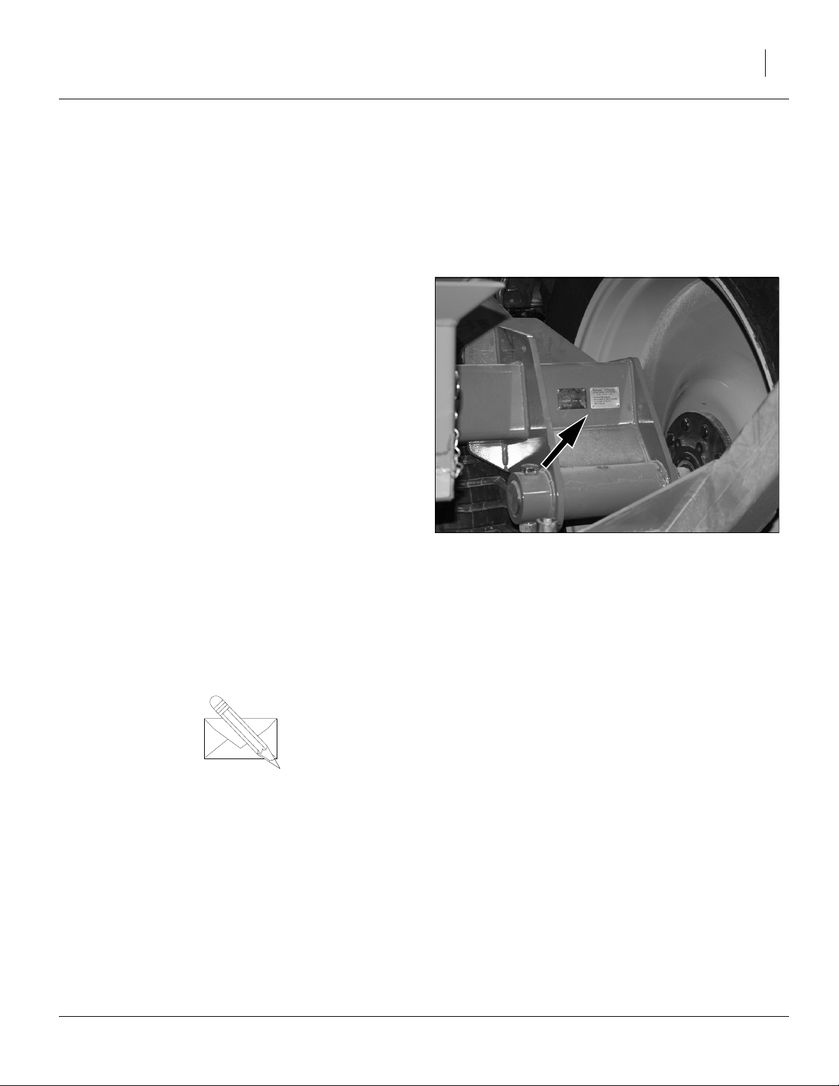
Refer to Figure 2
Your machine’s parts were specially designed and
should only be replaced with Great Plains parts. Always
use the serial and model number when ordering parts
from your Great Plains dealer. The serial-number plate is
located on the rear face or the right axle.
Record your Yield Pro Planter model and serial number
here for quick reference:
Model Number:__________________________
Serial Number: __________________________
Your Great Plains dealer wants you to be satisfied with
your new machine. If you do not understand any part of
this manual or are not satisfied with the service received,
please take the following actions.
1. Discuss the matter with your dealership service
manager. Make sure they are aware of any problems
so they can assist you.
2. If you are still unsatisfied, seek out the owner or general manager of the dealership.
For further assistance write to:
YP1220-3510
Product Support
Great Plains Mfg. Inc., Service Department
PO Box 5060
Salina, KS 67402-5060
Figure 2
Serial Number Plate
27456
03/14/2012 401-506M

12 YP1220 Great Plains Manufacturing, Inc.
Preparation and Setup
This section helps you prepare your tractor and planter
for use. Before using the planter in the field, you must
hitch the planter to a suitable tractor and level the planter.
Pre-Start Checklist
1. Read and understand “Important Safety Information” on page 1.
2. Check that all working parts are moving freely, bolts
are tight, and cotter pins are spread.
3. Check that all grease fittings are in place and lubricated. See “Lubrication” on page 64.
4. Check that all safety decals and reflectors are correctly located and legible. Replace if damaged. See
“Safety Decals” on page 6.
5. Inflate tires to pressure recommended and tighten
wheel bolts as specified. See “Tire Inflation” on
page 74.
401-506M 03/14/2012
Great Plains Manufacturing, Inc. Preparation and Setup 13
Hydraulic Hose Hookup
High Pressure Fluid Hazard:
Relieve pressure before disconnecting hydraulic lines. Escaping fluid under pressure can have sufficient pressure to penetrate the skin causing serious injury. Use a piece of paper or
cardboard, NOT BODY PARTS, to check for leaks. Wear protective gloves and safety glasses or goggles when working with
hydraulic systems. If an accident occurs, seek immediate medical attention from a physician familiar with this type of injury.
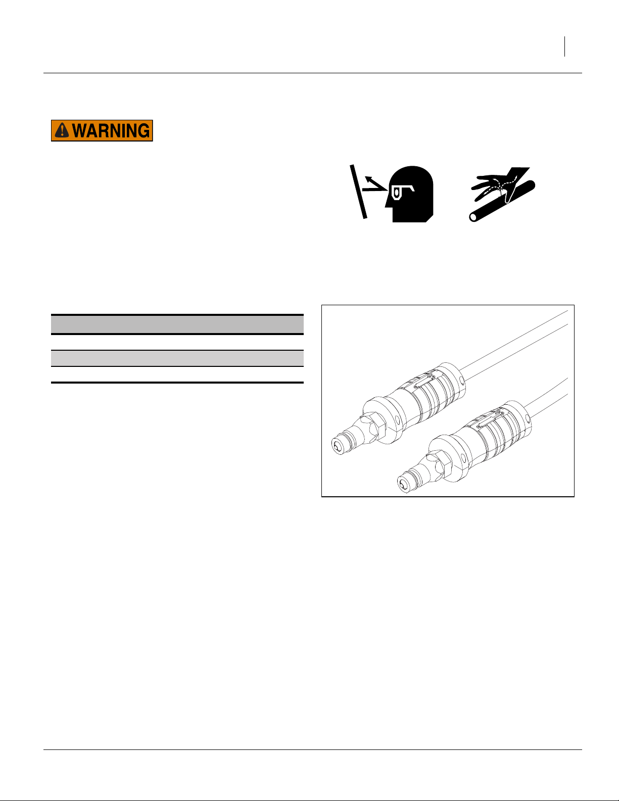
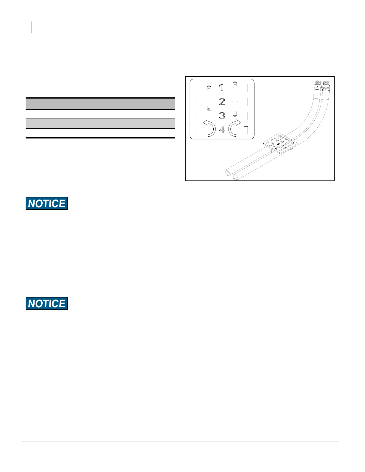
Refer to Figure 3
Great Plains hydraulic hoses have color coded handle
grips to help you hookup hoses to your tractor outlets.
Hoses that go to the same remote valve are marked with
the same color.
Current Style Color Coded Hose Handles
Color Hydraulic Function
Green Fold/Marker
Blue Lift/Tongue
Black Fan
To distinguish hoses on the same hydraulic circuit, refer
to the symbol molded into the handle grip. Hoses with
an extended-cylinder symbol feed cylinder base ends.
Hoses with a retracted-cylinder symbol feed cylinder
rod ends.
For hydraulic fan and drive motors, connect the hose
under the retracted cylinder symbol to the pressure side
of the motor. Connect the hose under the extended cylinder symbol to the return side of the motor.
The fan motor further requires hookup of a (third) case
drain line, which returns lubricating/cooling fluid.
Figure 3
Color Coded Hose Handles
31733
03/14/2012 401-506M
14 YP1220 Great Plains Manufacturing, Inc.
Older Style Hoses with Color Ties
Refer to Figure 4
Great Plains hydraulic hoses are color coded. Hoses that
go to the same remote valve are marked with the same
color tie.
Color Hydraulic Function
White Fold/Marker
Blue Lift/Tongue
Orange Fan
To distinguish hoses on the same hydraulic circuit, refer
to plastic hose label. Hose under extended-cylinder symbol feeds cylinder base ends. Hose under retracted-cylinder symbol feeds cylinder rod ends.
Protecting Hydraulic Motor Seals
Low Pressure (Case) Drain Connection
Figure 4
Plastic Hose Label
817-348C
17641
Motor Seal Damage Risk:
Case Drain Hose must be attached prior to inlet and return
hoses being connected. Also, it must be unhooked last to prevent damage to the fan motor.
1. Attach case drain hose to low pressure drain connection.
Note: Case drain hose must be hooked up first. Also, it
must be unhooked last to prevent damage to hydraulic motor seals.
2. Connect low pressure return hose to low pressure
return connector.
Hydraulic Motor Performance Risk:
DO NOT hook case drain line to a “power-beyond port”.
3. If the tractor has a limited number of remotes capable of continuous flow, use one for the fan. (See
“Specifications and Capacities” on page 74 for
tractor requirements.)
401-506M 03/14/2012
Great Plains Manufacturing, Inc. Preparation and Setup 15
Hitching Tractor to Planter
Crushing Hazard:
You may be severely injured or killed by being crushed
between the tractor and planter. Do not stand or place any
part of your body between planter and moving tractor. Stop
tractor engine and set park brake before attaching cables and
hoses.
High Pressure Fluid Hazard:
Escaping fluid under pressure can have sufficient pressure to
penetrate the skin causing serious injury. Avoid the hazard by
relieving pressure before disconnecting hydraulic lines. Use a
piece of paper or cardboard, NOT BODY PARTS, to check for
leaks. Wear protective gloves and safety glasses or goggles
when working with hydraulic systems. If an accident occurs,
seek immediate medical attention from a physician familiar
with this type of injury.
3-Point Hitch
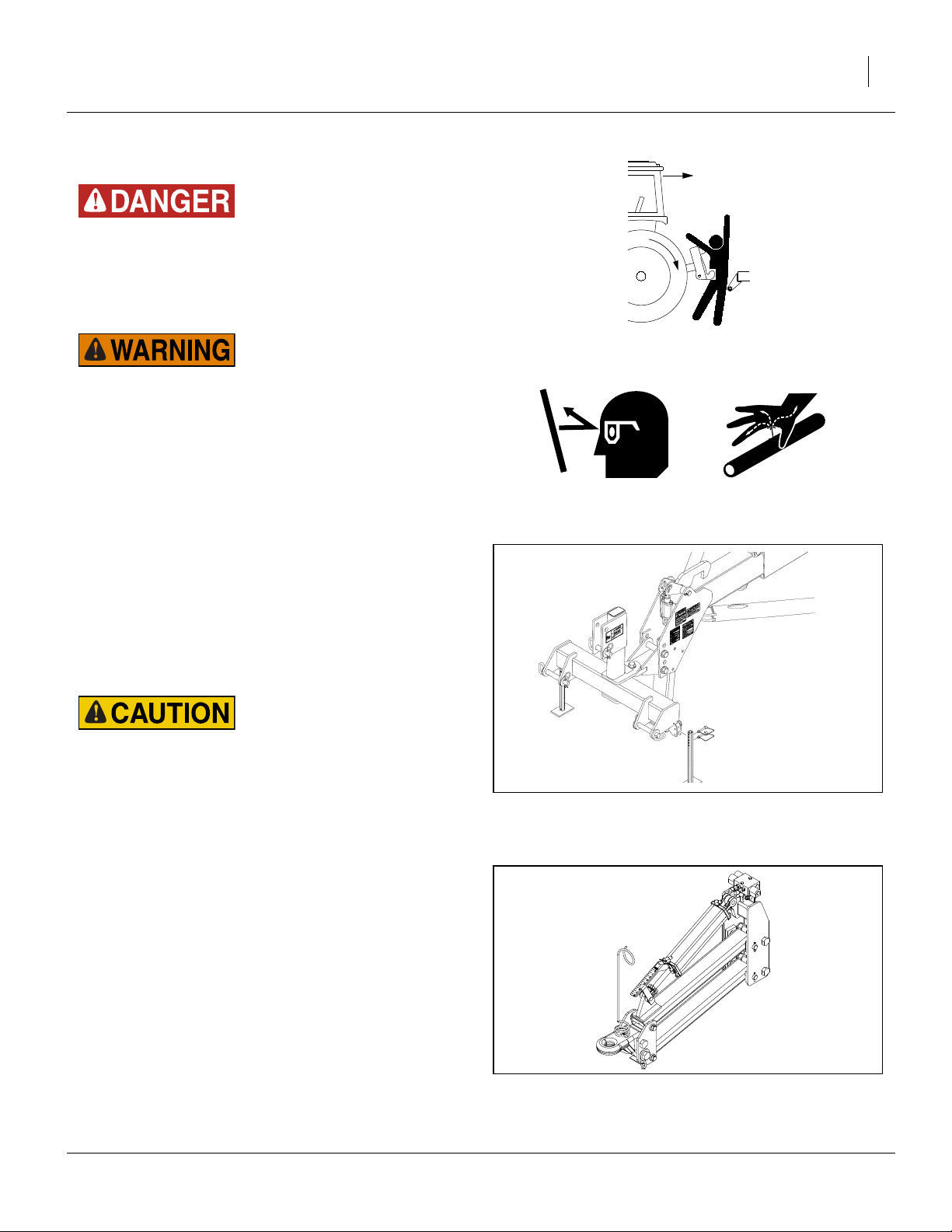
Refer to Figure 5
1. Connect your tractor 3-point to the planter 3-point
hitch. If using quick hitch be sure planter locks into
hitch securely.
2. Raise tractor 3-point just enough to relieve pressure
off of the parking stand.
Load Sway Hazard:
Adjust 3-point hitch arms and sway blocks to minimize any
side-to-side sway to assure proper tracking in the field and
safe road travel.
3. Connect hydraulic hoses to tractor remotes. See
“Hydraulic Hose Hookup” on page 13
Hydraulic Tongue Hitch
Refer to Figure 6
1. Connect the hydraulic hoses for the tongue circuit.
This needs to be done before hitching in order to
raise and lower the tongue.
2. Set the tongue height to clear the draw bar, back the
tractor into alignment and pin the draw bar.
Figure 5
3-Point Hitching
27282
Figure 6
Hitching with Hydraulic Tongue
03/14/2012 401-506M
25231
16 YP1220 Great Plains Manufacturing, Inc.
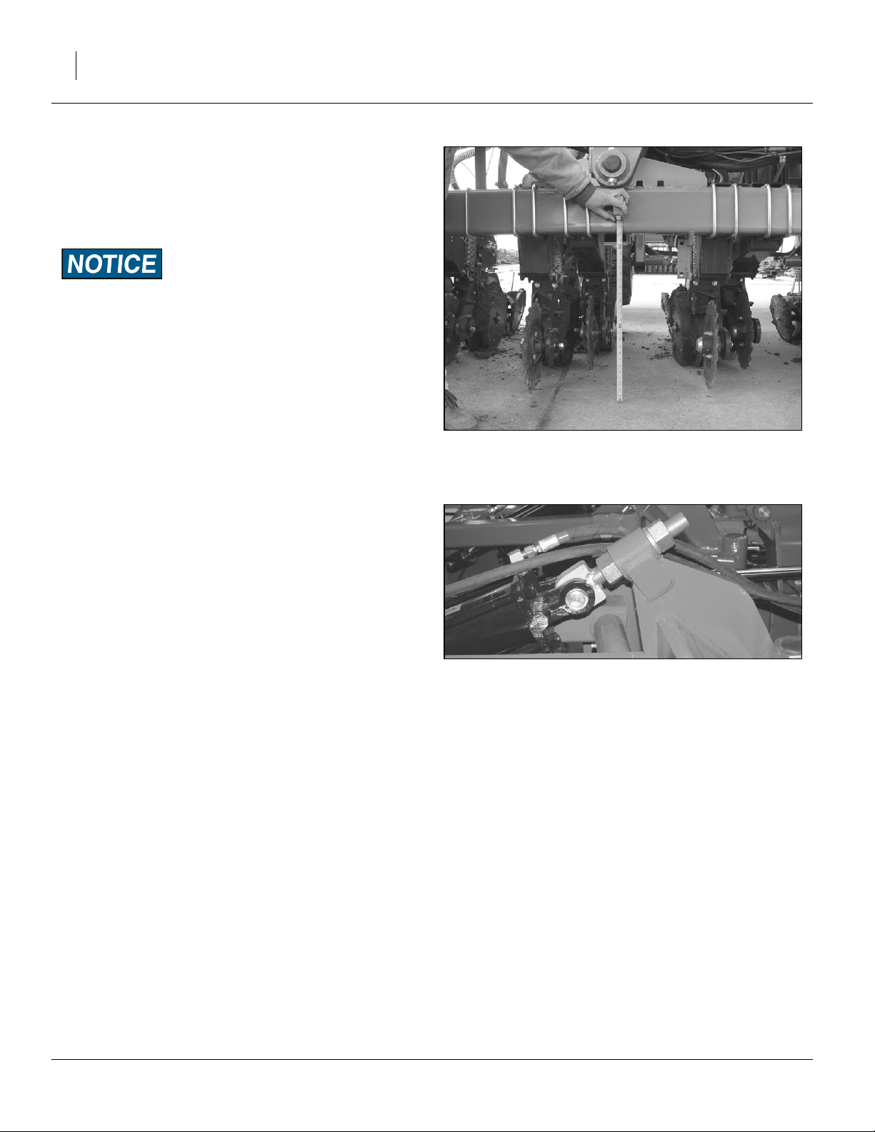
Tongue Height
3. Set the initial tongue height, using 3 point or cylinder
of hydraulic tongue. Distance ➀, measured at top of
tongue tube is:
46in above ground level.
4. Connect other hydraulic hoses to tractor remotes.
See “Hydraulic Hose Hookup” on page 13
5. Plug the planter light cable to the tractor.
6. Connect monitor lead to monitor harness.
7. Plug electric clutch cable to the switch control box
cable.
Note: Switch control boxes should be mounted in your
tractor cab in a location with easy access. Route
wiring harnesses with enough slack to allow for
tractor movement, especially on articulating tractors.
➀
Figure 7
Base Height
27457
Refer to Figure 8
8. Remove the lower pin ➀ holding the parking stand
➁. Swing the parking stand back and up until it is
above the rear hole ➂. Place the holding pin in the
rear hole and allow the parking stand to rest on it.
This will be the transport position for the parking
stand.
9. Adjust the top link of a 3-point long enough so the
ball swivel does not bottom out when fully raised.
10. Secure hoses so they do not get caught in ball
swivel. Failure to do so could cause hose to be
crushed requiring hose replacement.
2
3
1
Figure 8
Storing Parking Stand
22813
401-506M 03/14/2012
Great Plains Manufacturing, Inc. Preparation and Setup 17
Hydraulic Charge and Bleed
Normally the hydraulic system is fully charged and bled
at the factory before shipping. If repairs have been made,
substantial amount
s of oil drained from the system, or the following procedures do not correct a problem, see “Bleeding Hydrau-
lics” on page 55.
Lift Hydraulics
Bleeding should not be required other than to raise fully
and hold lever on for one minute or until all cylinders
extend fully. If this does
Cylinder Hydraulics
Bleeding should not be required other than to fold fully
and hold lever on for one minute or until all cylinders
reach the end of their stroke.
Planter Damage Risk:
Do not fold or unfold without first raising planter completely.
Leveling Frame Side-to-Side
All frame sections must be level to maintain even planting depth. Before using the planter in the field, follow
these steps to make sure the planter is level side-to-side.
Periodic frame-leveling adjustments should not be necessary, but if you are having problems with uneven
depth, check planter levelness and follow these procedures.
Before making any adjustments be sure the lift cylinders
are re-phased and operating properly.
Complete the steps under “Hydraulic Charge and
Bleed” on page 17, before proceeding.
Note: Level frame in planting conditions. Failure to do so
may result in machinery not producing desired results.
Refer to Figure 9
1. Unfold the planter fully and set down. Put in field
position by lowering and pulling forward.
➀
Figure 9
Base Height
27457
03/14/2012 401-506M
18 YP1220 Great Plains Manufacturing, Inc.
Refer to Figure 9 on page page 17
2. When setting hitch, lower lift cylinders completely.
Set the 3-point hitch or hydraulic tongue so that the
top of the tongue tube
➀ is:
46in above ground.
This is the starting point for adjustments.
Field Results Risk:
Planter must be fully lowered to field position and hitch height
must be set before making side-to-side adjustments.
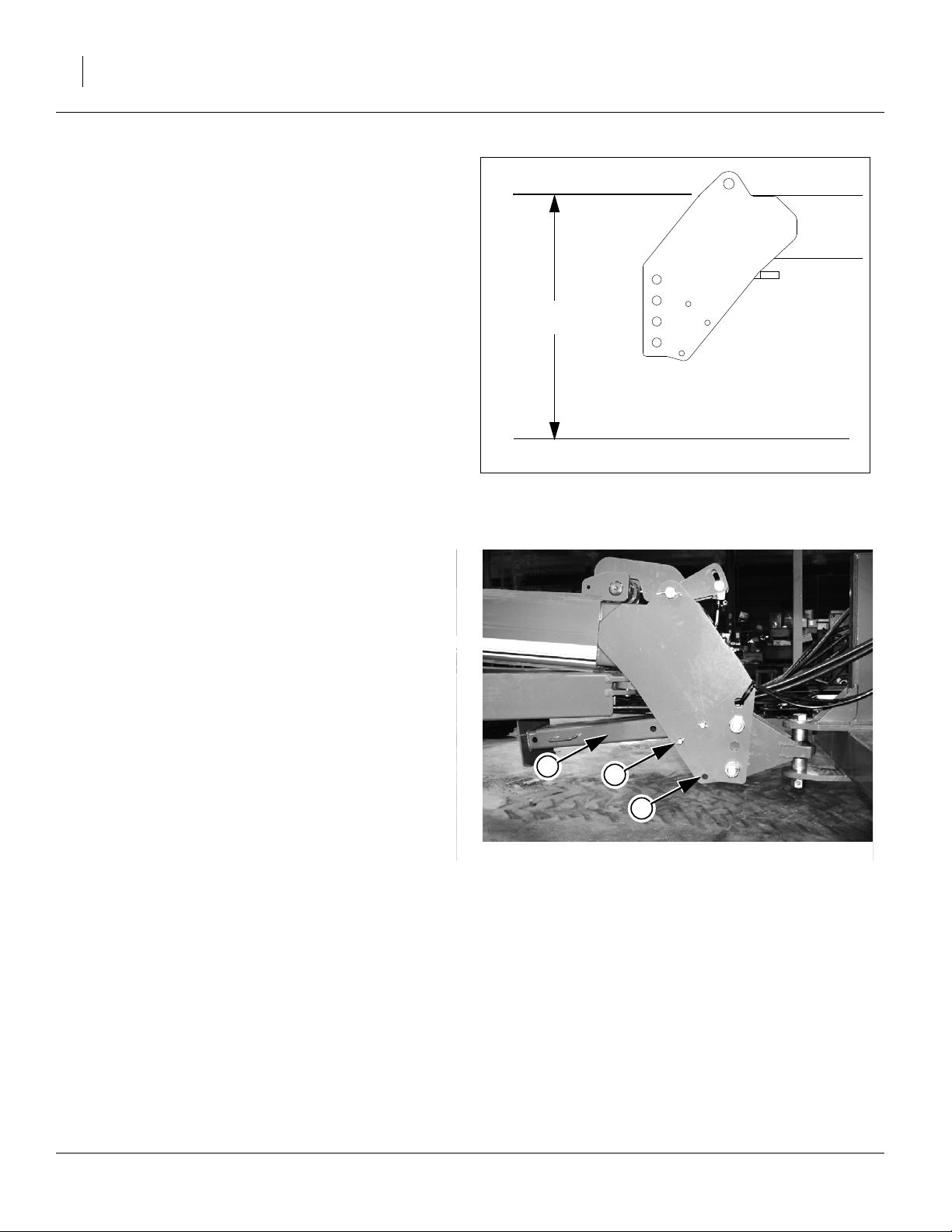
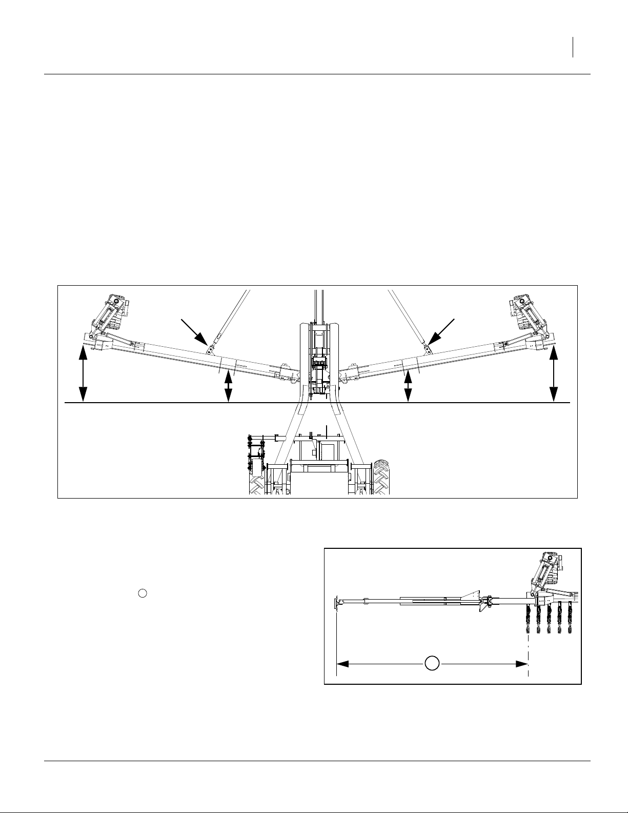
Refer to Figure 10
1
⁄
3. If planting 1
in deep, adjust the hitch until frame
2
measures approximately 26in from ground to frame
at the pivots.When planting at other depths, frame
height will vary.
Note: Parallel arms should be parallel with ground or up
to 1in lower in back. Adjusting a 3-point hitch to level parallel arms may cause frame to sit higher or
Figure 10
Frame Leveling
23087
lower than 26in.
4. Check parallel arms behind the pivots to ensure that
parallel arms are parallel with ground or up to 1in
lower in back. If needed, raise or lower the 3-point to
adjust parallel arms.
5. Once parallel arms are parallel with ground or up to
1in lower in back and 3-point is set, measure distance from ground to frame at the pivots.
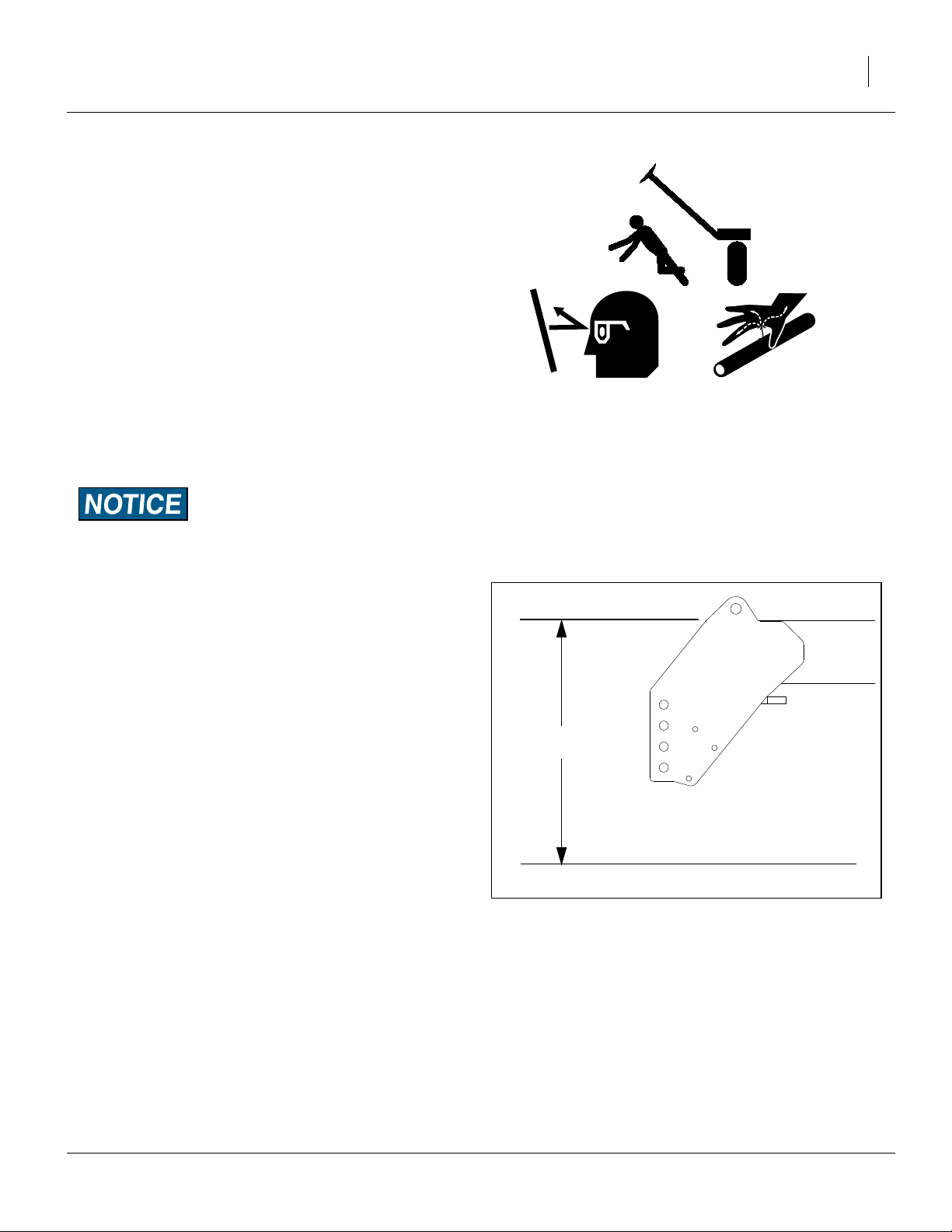
Refer to Figure 11
6. Measure wings at gauge wheel. If not level with center of frame, adjust eye bolt accordingly.
Note: Eye-bolt adjustments are easier if the planter is first
lowered to the ground to remove some of the force
Figure 11
Eye Bolt Adjustment
21930
on the cylinder.
401-506M 03/14/2012
Great Plains Manufacturing, Inc. Preparation and Setup 19
Wing Alignment
To check and adjust wing alignment:
1. Unfold planter, see “Unfolding the Planter” on page
24, and place a block ahead of each wing gauge
wheel. Pull planter forward against blocks to rock
frames back.
Refer to Figure 12
2. Check for proper alignment by running a string line
across back of planter toward outer ends of wings.
For proper alignment, outside ends of wings (dimen-
sion A) should be 0-to(dimension B).
1
⁄
in ahead of inside ends
4
3. To adjust wing alignment, shorten or lengthen eye
bolts to change the length of the wing pull bar. Adjust
eye bolts ➀ in or out until dimension A is 0 to
greater than dimension B.
4. Be sure both wings are adjusted equally or the
planter will tend to pull sideways behind the tractor.
Note: Angle of wings is exaggerated for ease of clarifica-
tion.
1
⁄
in
4
➀
Figure 12
Box Alignment
Marker Extension
Prior to first marker use during planting, unfold each
marker side in field conditions, and check marker exten-
sion. The distance from the mark to the centerline of
each end row unit is:
185in (470cm).
Check also that the mark left is sufficiently visible for your
soil and residue conditions.
For changes, see “Marker Adjustments” on page 41.
1
➀
21931
1
Figure 13
Marker Extension
03/14/2012 401-506M
27451

20 YP1220 Great Plains Manufacturing, Inc.
Optional Monitor Mounting Plate
The Yield-Pro Planter® is supplied with an optional
mounting plate that may be used to mount the Point Row
Monitor, the Electro-hydraulic Control Valve, and the
DICKEY-john® Seed Monitor.
Refer to Figure 14
1. Attach large suction cup included with mounting
plate to the top hole on the plate using bolt and lock
washer.
2. Place DICKEY-john® mounting bracket on mounting
plate. Secure bracket to plate in bottom two holes
directly below the suction cups. Use bolts and nuts to
install.
3. Remove mounting bracket from electro-hydraulic
valve control. Install mounting bracket to mounting
plate.
4. Attach point row monitor to mounting plate with 10-
5
32 x
⁄
machine screws, lock washers, and nuts. Let
8
wires fall in the front of the plate.
5. Secure electro-hydraulic valve control to mounting
bracket on plate using 10-32 x
5
⁄
machine screws,
8
lock washers, and nuts. Let wires fall in the front of
the plate.
6. Attach DICKEY-john® Monitor to DICKEY-john®
mounting bracket on plate. Thread monitor wires
through slot in plate. Trap all other wires between
DICKEY-john® monitor and mounting plate.
Point Row
Monitor
Electro-hydraulic
Valve Control
DICKEY-john®
Monitor
Figure 14
23283
Optional Monitor Mounting Plate
401-506M 03/14/2012

Great Plains Manufacturing, Inc. Operating Instructions 21
Operating Instructions
This section covers general operating procedures. Experience, machine familiarity and the following information
will lead to efficient operation and good working habits.
Always operate farm machinery with safety in mind.
Pre-Start Checklist
High Pressure Fluid Hazard:
Escaping fluid under pressure can have sufficient pressure to
penetrate the skin. Check all hydraulic lines and fittings before
applying pressure. Fluid escaping from a very small hole can
be almost invisible. Use paper or cardboard, not body parts,
and wear heavy gloves to check for suspected leaks. If an accident occurs, seek immediate medical attention from a physician familiar with this type of injury.
1. Carefully read “Important Safety Information” on
page 1.
2. Lubricate planter as indicated under “Lubrication”
on page 64.
3. Check all tires for proper inflation. See “Tire Infla-
tion” on page 74.
4. Check all bolts, pins and fasteners. Torque as shown
in “Torque Values Chart” on page 75.
5. Check planter for worn or damaged parts. Repair or
replace parts before going to the field.
6. Check hydraulic hoses, fittings and cylinders for
leaks. Repair or replace before going to the field.
7. Be sure hydraulic hoses are securely held out of the
ball swivel area at hitch. Failure to do so could cause
hoses to pinch requiring hose replacement.
03/14/2012 401-506M
22 YP1220 Great Plains Manufacturing, Inc.
Folding the Planter
Pinch Point and Crushing Hazard:
To prevent serious injury or death:
▲ Fold only if hydraulics are bled free of air and fully charged
with hydraulic oil.
▲ Stay away from frame sections when they are being raised
or lowered.
▲ Keep away and keep others away when folding or unfolding
planter.
Fold planter on level ground with tractor in neutral. If your
planter has markers, be certain they are folded.
Crushing Hazard:
Center section of planter will move backward while folding.
Allow at least 10ft of clearance behind the planter when folding.
1. Switch drive line clutches off.
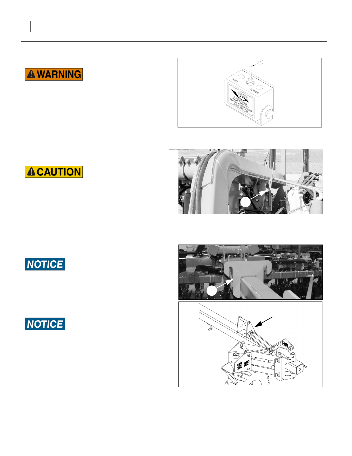
Refer to Figure 15
2. Set electronic valve selector switch ➀ in tractor to
“FOLD” to activate fold cylinder hydraulics.
3. Activate lift hydraulics. Raise planter until lift hydraulics are fully raised.
Figure 15
Selector Switch
➁
Figure 16
Transport Hooks
21980
25030
Planter Damage Risk:
Be sure planter’s lift hydraulics are fully raised before folding
or machine damage WILL occur.
Refer to Figure 16
4. Fold planter until wings clear transport hooks ➁ by a
few feet.
➂
➃
Planter Damage Risk:
Failure to keep the 3-point lowered while folding WILL result
in opener or seed delivery system damage.
5. Raise 3-point hitch to elevate wing hooks located on
the tongue above the wings.
6. Fold planter fully so wing locks can engage the wing
hooks ➃.
Refer to Figure 17
7. Lower 3-point hitch to engage wing hooks so tongue
is carried on the wing locks. Allow hitch to float with
planter frame while transporting.
401-506M 03/14/2012
Wing Hook & Wing Lock
Figure 17
22815
27288
Great Plains Manufacturing, Inc. Operating Instructions 23
Refer to Figure 19 and Figure 18
8. Remove lift cylinder transport lock channels from
their storage positions.
Figure 19
Transport Cylinder Lock Storage
Refer to Figure 19 and Figure 18
9. Place transport lock channels on lift cylinders
located on gauge wheels and on center frame.
Figure 21
Transport Cylinder Lock Use
27290
27452
Figure 18
Lift Cylinder Lock Storage
Figure 20
Lift Cylinder Lock Use
25029
27289
03/14/2012 401-506M

24 YP1220 Great Plains Manufacturing, Inc.
Unfolding the Planter
Crushing, Pinch-Point and Overhead Hazards:
To prevent serious injury or death:
▲ Fold only if hydraulics are bled free of air and fully charged
with hydraulic oil.
▲ Stay away from frame sections when they are being raised
or lowered.
▲ Keep away and keep others away when folding or unfolding
planter.
Unfold planter on level ground with tractor in neutral.
1. Switch drive line clutches off.
Refer to Figure 22
2. Set electronic valve selector switch in tractor to
“FOLD” to activate fold cylinder hydraulics.
3. Activate lift hydraulics. Raise planter until lift hydraulics are fully raised.
Figure 22
Selector Switch
➁
21980
Planter Damage Risk:
Be sure planter’s lift hydraulics are fully raised before unfolding or machine damage WILL occur.
Refer to Figure 23
4. Raise 3-point hitch to release wing hooks.
5. The fold system uses re-phasing cylinders. It is necessary to re-phase cylinders so wing gauge wheels
to run in their fully rotated positions in front of planter.
To re-phase fold cylinders:
Move and hold lever in fold direction for 30 seconds.
This causes wings to push against the tongue transport hooks.
Refer to Figure 24
6. Reverse fold lever until wings clear transport hooks
by a few feet.
7. Lower 3-point hitch to planting position. See page 15
and page 29 for correct hitch height and depth control settings.
Planter Damage Risk:
Failure to lower the 3-point before unfolding WILL result in
opener or seed delivery system damage.
8. Unfold planter fully to planting position.
➂
Figure 23
Transport Hooks
➃
Figure 24
Wing Hook & Wing Lock
25030
22815
27288
401-506M 03/14/2012

Great Plains Manufacturing, Inc. Operating Instructions 25
Refer to Figure 18 through Figure 21 on page 23.
9. Remove lift cylinder transport lock channels from
gauge wheels and center frame. Return transport
lock channels to storage area.
10. Activate lift hydraulics and lower planter.
11. Set electronic valve selector switch in tractor to
“MARKER” to activate marker hydraulics.
12. Switch drive-line clutches on.
Changing the Seed Box or Hopper
1. Shut off fan before changing boxes.
2. Park the planter on level ground with enough room to
maneuver a tractor with front-end loader around it.
3. Place tractor in park, shut off engine, and remove the
key.
4. Close the slide gate.
Refer to Figure 25
5. Remove the walkboard lock pin
➀.
6. Swing walkboard ➀ all the way to the right.
Figure 25
Walkboard Lock Pin
27453
Note: If planter is lowered, walkboard ➀ will stay open by
itself once fully opened.
Refer to Figure 26
7. Remove the pins restraining the seed box or bulk
hopper on the frame. (There are two lock pins one
each on diagonal corners).
Refer to Figure 27
Align the forks with the slots in the rear of the seed box or
hopper and slowly drive forward until forks are completely under the seed box or hopper.
Slowly lift the empty seed box or hopper from the planter.
Carefully install full seed box or an empty hopper on the
planter. Install box restraining pins in opposite corners.
Note: Bulk hopper frame has two sets of lifting points.
One set is for normal loading and is tubes. The other set is to allow picking it up from the side for placing in storage near a wall.
Tipping and Overload Hazard:
Never attempt to move a seed hopper while loaded. It exceeds
the lifting capacity of front end loaders and most fork lifts.
Always fill seed hopper with seed after it has been securely
placed back on the air box.
Note: It may be necessary to adjust the seal on top of air
box to get full contact with the bottom of seed box or
hoppers. This is a one-time adjustment.
Figure 26
Seed Box Pins
Figure 27
Fork-Lifting Seed Box
25036
25036
03/14/2012 401-506M

26 YP1220 Great Plains Manufacturing, Inc.
8. Load the hopper with seed. If using a hydraulic auger
with the auxiliary hydraulic kit, refer to the instructions following.
9. Open the slide gate.
10. Return the ladder and platform to the closed position.
Flow Inconsistency and Stoppage Risk:
Talc lubricant is mandatory for all seeds, especially treated or
inoculated seed when using the precision meter. Do not use
talc lubricant when using the finger pickup meters. Use graphite lubricant with finger pickup meters. Refer to “Seed Lubri-
cants” on page 71.
Using Auxiliary Hydraulic Circuit
The optional auxiliary hydraulic kit includes a manual
valve that diverts the marker hydraulic circuit to a pair of
quick-connect ports at the back of the seed cart.
1. Extend or fold any marker that is raised. Return the
cab control for that circuit to “off”.
2. Close any shut-off valve on your auger, and connect
the auger to the auxiliary quick-connect ports at the
back of the seed cart.
3. At the auxiliary selector valve (near marker
sequence valve on left wing), move the handle from
“Marker” to “Auxiliary”.
4. With no seed present, open the auger shutoff valve,
and operate the cab control to determine which setting (“extend” or “retract”) turns the auger in the correct direction for seed lift.
5. Load seed. Shutoff cab circuit, then auger. Return
Aux valve control handle to “Marker” position.
Pre-Usage Checklist
Use the following checklist as a guide to ensure the
planter is proper set before using. You may need to refer
to the assembly instructions, operator’s manual or the
Dickey-john manual to complete checklist.
MECHANICAL
❑ 1. Tongue height preset on 3-point.
❑ 2. Front to rear levelness.
❑ 3. End-to-end levelness at gauge wheels.
❑ 4. Toe in of wing frames at pull-bars.
❑ 5. Tongue hook latch operation.
❑ 6. Marker initial length.
AIR SYSTEM
❑ 7. Manifold to Pro-box or poly hopper seal.
❑ 8. Y-splitters turned on to correct rows.
9. Air leaks (small leaks from Pro-box are nor-
❑
❑
❑ 11. Cleanout doors closed at meters.
❑
❑
❑
❑ 15. Check closing wheel alignment.
❑
❑
❑ 18. Lock up splitter rows if needed.
❑
mal.
10. Hose routings, no sags and no pinched
hoses. (Check both folded and field positions.)
12. Hoses fully connected to meters and
locked.
ROW-UNITS
13. Preset depth handles to 7 holes showing
above “T”
14. Preset down force springs to 1st notch
(lightest) setting for most conditions, 2nd
notch otherwise.
16. Set closing wheels to first notch (light setting).
17. Check meter drive coupler is engaged for
all desired rows.
19. Check action and contact of side depth
wheels.
401-506M 03/14/2012

Great Plains Manufacturing, Inc. Operating Instructions 27
HYDRAULIC
❑ 20. Field raise and lower.
❑ 21. Fold/unfold and tongue lock.
❑ 22. Markers.
❑ 23. Solenoid valve.
❑ 24. Fan direction and speed.
DRIVE
25. Check all chains are lubricated, proper ten-
❑
❑
❑ 27. Check contact wheel pressure.
❑
❑
❑
sion and move freely without kinks or tight
spots. (This is very important for even
metering.)
26. Set range & transmission sprockets for
desired rate.
28. Check action of contact wheel when raising and lowering it makes contact at
ground height.
29. Lubricate slider joints on drive shafts if not
already done.
30. Check operation of electric clutches for
point rows.
METERS
31. Correct meters for desired crop. (Precision
❑
❑
❑
❑
❑ 35. Cleanout doors closed.
❑
❑
Finger Pickup or Singulator Plus.)
32. Correct seed wheels for desired crop.
(Wheels for planters are green in color, not
black.)
33. Seed wheels need to be fully seated in
meter.
34. Correct 12 finger or 6 finger units on all
rows for your row spacing. (Can be
checked by looking into cleanout door
opening.)
36. Meter assemblies properly secured in
place.
37. Graphite for Precision Finger Pickup
meters or Talc for Singulator Plus meters
(per manual).
ELECTRICAL
❑ 38. Power up monitor and check settings.
39. Power up and check hydraulic settings if
❑
❑
❑ 41. Check operation of lighting equipment.
not already done.
40. Check operation of selector valve for fold/
makers.
03/14/2012 401-506M

28 YP1220 Great Plains Manufacturing, Inc.
Transporting
Loss of Control Hazard:
Towing the planter at high speeds or with a vehicle that is not
heavy enough could lead to loss of vehicle control. Loss of
vehicle control could lead to serious road accidents, injury
and death. To reduce the hazard, do not exceed 20 mph.
Before transporting the planter, follow and check these
items:
• Set the tractor 3-point hitch control for depth control
operation. If the 3-point hitch control is set for load
control, the auto load control response may automatically adjust too high in given circumstances. This will
result with the wing locks disengaging on the road.
• Empty seed box. Empty seed box before transporting
if at all possible.
• The planter can be transported with a full box of grain,
but the added weight will increase stopping distance
and decrease maneuverability.
• Transport planter only while in folded position. Refer to
“Folding the Planter” on page 22 and make sure cylinder lock channels are in place on the gauge wheels.
• Warning lights. Always use warning lights when transporting the planter.
• Road rules. Comply with all federal, state, and local
safety laws when traveling on public roads.
• Clearance. Remember that the planter is wider than
the tractor. Allow safe clearance.
• Transporting with Markers. Always transport markers
in the folded position. Make sure second marker section rests securely on transport carrier.
401-506M 03/14/2012

Great Plains Manufacturing, Inc. Operating Instructions 29
Field Operation
1. Hitch planter to a suitable tractor. See “Hitching
Tractor to Planter” on page 15.
2. Make sure proper meter wheels are in place.
3. Make sure all seed meter clean out doors are closed.
See “Cleaning Out Meters” on page 56.
4. Set planting rate. See “Planting Rate” on page 38.
5. Set tractor 3-point hitch control for depth control
operation - not load control.
Note: If tractor 3-point hitch control is set for load control,
hitch movement may cause changes in row unit
depth resulting in uneven depth control.
Approximate capacity (in bu) of
82bu hopper, at 10in increments
6. Set tongue height with planter lowered, to 46in. See
“Leveling Frame Side-to-Side” on page 17.
7. Turn on fan. Set tractor hydraulic flow control to
obtain the rpm from the table below, as indicated on
system monitor.
3800 rpm using 82bu or 150bu hoppers
3500 rpm using bulk seed boxes
Note: Refer to page 33 for further information.
8. Pull forward, lower planter, and begin planting.
9. Always lift planter out of ground when turning at row
ends and for other short-radius turns. Planting will
stop automatically as planter is raised.
10. Use tractor hydraulics to raise/lower planter, not tractor 3-point.
Seed Hopper Sensor
Refer to Figure 28 and Figure 29
For planters equipped with optional 82 bu. or 150 bu.
hoppers, an extra level sensor is included. Use Figure 28
or Figure 29, showing capacity, to place it at the level that
suits your operation. Disconnect sensor in manifold and
attach lead to this sensor to use it.
Figure 28
82 Bu Bulk Hopper
Approximate capacity (in bu) of
150bu hopper, at 10in increments
Figure 29
150 Bu Bulk Hopper
22958
22958
03/14/2012 401-506M

30 YP1220 Great Plains Manufacturing, Inc.
Monitor Operation
For monitor operation, refer to the DICKEY-john ® manual supplied with this unit.
Refer to Figure 30
The monitor uses a pickup wheel for measuring planter
ground speed. The pickup sensor should be set at a dis-
tance of
1
⁄
16
in to
1
⁄
in from pickup wheel.
8
Electric Clutch Operation
Refer to Figure 31
Electric clutches allow for turning planting off while the
planter is lowered. A clutch for each drive shaft allows for
independent control each of side of the planter. The
clutches are controlled via the in cab control console.
For regular field operation, turn electric clutch switches
on control console to “ON” position. This will activate the
magnet on each clutch and allow clutch shafts to rotate.
To shut off planting on one or both sides to accommodate point row while planter is lowered, turn one or both
switches to “OFF” position.
Figure 30
Pickup Wheel
Figure 31
Electric Clutch Switch
25318
19694
401-506M 03/14/2012

Great Plains Manufacturing, Inc. Operating Instructions 31
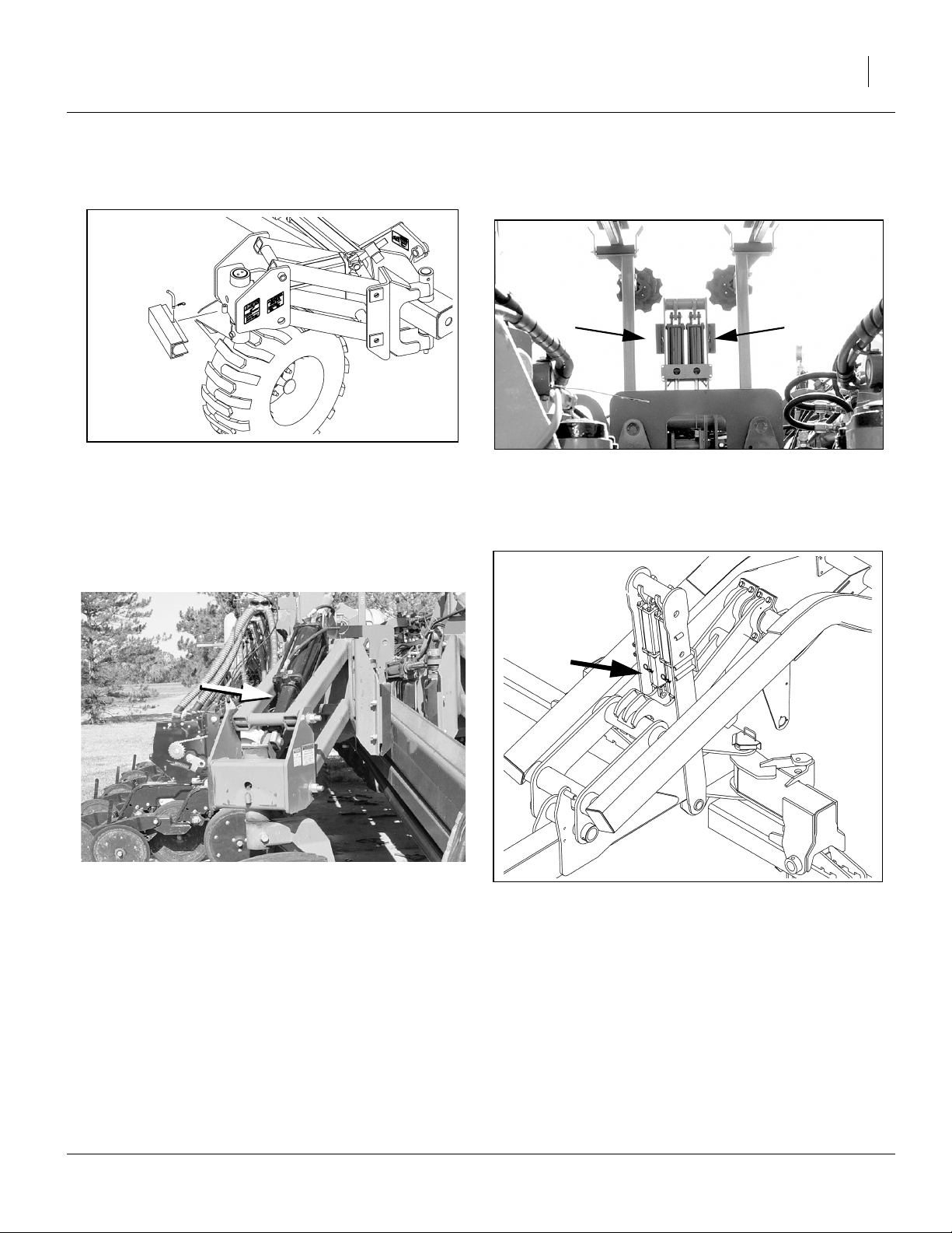
Electric Clutch Lockup
Refer to Figure 32
In case of electric clutch failure, electric clutches can be
bolted together.
1. Align cutouts at bolt holes ➀.
2. Insert M8-1.25x14mm long metric bolts ➁.
Note: Use only 14mm length bolts as provided or ma-
chine damage will occur. Longer bolts will damage
the clutch. Shorter bolts may not effect a lock-up.
3. Unbolt field coil housing and make sure it is allowed
to move freely.
22906
If you observe half the hole obstructed by a metal disc
4
, you are not at a cutout.
Figure 32
Electric Clutch Lockup
If the entire hole is obstructed by a metal disc , you are
not at a cutout.
When at a cutout, the bolt will screw in with minimal
resistance until the bolt head reaches the clutch face.
Machine Damage Risk:
When lubricating the planter, do not allow lubricant to enter
the clutch, or clutch slippage will result.
4
Row-Unit Operation
Machine Damage Risk:
IMPORTANT! Do not back up with row-units in the ground,
because this will cause severe damage and row-unit plugging.
For information on row-unit adjustments, see “20 Series
Row-Unit Adjustments” on page 43. For more informa-
tion on troubleshooting row-unit problems, see “Troubleshooting” on page 50.
4
Figure 33
Clutch Plate Nearly at Cutout
1
26168
03/14/2012 401-506M

32 YP1220 Great Plains Manufacturing, Inc.
Marker Operation
Before operating markers, make sure they are properly
bled as described in “Bleeding Hydraulics” on page 55.
Dual markers are equipped with a sequence valve to
control lift sequence. Starting with both markers up, the
sequence is:
1. If the planter is equipped with an auxiliary hydraulic
system, set the selector valve (found near the
sequence valve at the marker base on the left wing)
to “Marker”.
2. Activate tractor hydraulic lever; right marker lowers
while left marker stays up.
3. Reverse hydraulic lever; right marker raises while left
marker stays up.
4. Activate hydraulic lever; left marker lowers while right
marker stays up.
5. Reverse hydraulic lever; left marker raises while right
marker stays up.
6. Pattern repeats.
Folding speed of dual markers is adjusted with adjustment screws on sequence valve body. Because excessive folding speed may damage markers, adjust markers
to a safe folding speed according to “Marker Adjust-
ments” on page 41.
Note: To get both markers in the lowered position at the
same time, activate hydraulic lever to lower one
marker. After marker is lowered, move lever to
opposite position then quickly reverse lever and
hold until other marker is lowered.
Re-phasing Lift System
Over a period of normal use the cylinders may get out of
phase. This will cause some planter sections to run
higher than others. If this is the case, it will be necessary
to re-phase lift cylinders. NOTE: Lift cylinders can only
be re-phased when planter is unfolded.
To re-phase cylinders:
1. Raise the implement completely and hold the
hydraulic remote lever on for several seconds until all
cylinders are fully extended. Do this every 8 to 10
times you raise planter out of ground.
2. When all cylinders are fully extended, momentarily
reverse hydraulic remote lever to retract system
1
⁄
in
2
to maintain levelness.
Re-phasing Fold System
Over a period of normal use, the cylinders may get out of
phase. This is evident by wing gauge wheels not running
in their fully rotated positions in front of the planter.
Note: Planter must be folded to re-phase fold system.
Refer “Unfolding the Planter” on page 24, for
instructions on re-phasing fold system.
401-506M 03/14/2012

Great Plains Manufacturing, Inc. Operating Instructions 33
Airbox Operation
The function of the airbox is to carry seed to the meter
where seed is blown to the row spacings.
Fan Operation
The fan must hook up to the case drain line first, and it
must be operated with the return oil line connected to a
low back pressure sump return on the tractor. Check with
tractor manufacturer for proper connection of oil sump
return line. A low back pressure quick disconnect is supplied with the planter for ease of connection to the tractor
sump return line.
Use tractor remote hydraulic valve flow control to set fan
speed. Start with flow on low setting. 8 - 12 gpm is average flow.
Note: Do not apply pressure to the return line or operate
with restricted return line or motor seals will be
damaged.
Recommended butterfly valve setting is 0
mended fan speed depends on planter configuration:
3800 rpm using 82bu or 150bu hoppers
3500 rpm using bulk seed boxes (or legacy Great Plains
hoppers without the vent line update)
°. Recom-
2
Figure 34
Y-Tubes
1
27458
Do not run the fan at speeds over 4500 rpm or speeds
under 3000 rpm. Fans operating at too high a speed create too much air flow causing seed to plug up the meter
box. Fans operating at too low a speed do not create
enough air flow to push the seed to the meter causing
the seed tube to plug. If air system does not operate suitably with fan speeds between 3000-4500 rpm, see
“Troubleshooting” on page 50, and then “Fan Adjust-
ments” on page 42.
When starting empty you must blow seed out to the
meters for two to four minutes to fill meters.
Note: Before corn planting for the first time at the start of
each season, add
1
⁄
cup graphite to bottom of air-
3
box.
Watch monitor and adjust fan speed by increasing or
decreasing hydraulic flow from tractor.
The monitor has a level sensor located below hopper to
warn when box is empty. This gives three to four acres of
run time before rows start going empty.
Y-Tubes
Refer to Figure 34
Most rows are connected via Y-tubes with valves .
These Y-tube gates can be shut off to increase the row
spacing of your planter.
Three rows are connected to fixed Y-tubes without valves
2
. These rows cannot be shut off at the Y-tube. Plan any
alternate row spacings to use these always-open rows,
or un-clamp and re-route seed hoses.
You can also shut off the valved Y-tube gates to clean out
the air system and meters. See “Cleaning Out Air Sys-
tem” on page 59.
1
03/14/2012 401-506M

34 YP1220 Great Plains Manufacturing, Inc.
Airbox Troubleshooting
Problem Cause Solution
Single row doesn’t fill or keep up with
other rows.
Both rows on one meter outlet low or
not keeping up with other rows.
Note: This is more likely to occur on
end outlets.
Multiple rows fail for lack of seed. Fan speed too high/too low. Check/adjust fan speed.
Single or multiple hoses plugging just
ahead of airbox.
All rows fail. Lack of seed. Fan speed too high. Adjust fan speed.
1, 2, 3, or more outlets fail.
Outlets can be side-by-side or random.
Plugging may also move from one outlet to another.
Little or no seed to a lot of rows with
heavily treated seed.
Y tube is bent/angled off feed
pipe.
Drop tube to meter is too long,
causing seed to pool and plug
hose or Y-tube.
Blockage in air slot in top of airbox.
Bad hose routing between delivery hose and airbox on wing.
Out of seed. Add seed.
Fan speed too high/too low. Check/adjust fan speed.
Possible air leak. Check for air leak downstream
Foreign matter in seed chamber
in bottom of airbox.
Seed treatment sticky. Add talc to seed to dry out seed treat-
Loosen pipe and spin so the bend is
straight down and Y-tube is not pointing to front or rear of air pipe.
Shorten hose (with planter raised, but
row units lowered, to ensure hose is
not too short).
Clear by using a long skinny tool and
taking hose off through hose outlet.
It may be necessary to take top off airbox to clear junk from slot.
Correct hose routing.
between box and top of meter.
Extremely high populations may
require slightly reduced field speed.
Clean out seed chamber.
ment.
401-506M 03/14/2012

Great Plains Manufacturing, Inc. Operating Instructions 35
Parking
For information on long-term storage, see “Storage” on
page 36.
1. Fold planter. see “Folding the Planter” on page 22.
Note: Be sure to install cylinder lockup channels. Failure
to do so may result in injury and/or damage to the
planter.
2. Park planter on a level, solid area.
3. To prevent rolling, block tires securely.
Roll-Away Hazard:
There is not enough weight on parking stand(s) to anchor
planter. Planter wheels must be blocked when unhitching from
tractor. DO NOT unhitch planter while on a steep slope.
Refer to Figure 35
3 Point Hitch
4. Remove pin holding parking stand in “UP” position.
Swing stand down. Pin stand in parking position. If
the ground is soft, place a board or plate under the
stand.
5. Remove wire snap lock pin from innermost hole on
park stand mount. Swing support stand from underneath crossbar weldment.
6. Secure 3-point prop stands by inserting previously
removed wire snap lock pin in lower outermost hole
on park stand mount.
7. Lower tractor 3-point until planter is resting on parking stand.
8. Shut down hydraulics. Unplug hydraulic lines from
tractor. Do not allow hose ends to rest on the ground.
9. Unplug planter light cable from tractor.
10. Unplug monitor harness from console.
11. 3-point: Unhook tractor from planter hitch.
12. Pull tractor away.
Figure 35
Jack and 3-Point Prop Stand
22814
27282
03/14/2012 401-506M

36 YP1220 Great Plains Manufacturing, Inc.
Storage
Store the planter where children do not play. If possible,
store the planter inside for longer life.
1. Remove seed box. See “Changing the Seed Box or
Hopper” on page 25.
2. Thoroughly clean seed and seed treatment residue
from seed meters. See “Cleaning Out Meters” on
page 56, for more information.
3. Remove any dirt and debris that can hold moisture
and cause corrosion.
4. Lubricate and adjust all roller chains.
5. See “Lubrication” on page 64, for lubrication information.
6. Inspect planter for worn or damaged parts. Make
repairs and service during off season.
7. Use spray paint to cover scratches, chips, and worn
areas on the planter to protect the metal.
8. Cover with a tarp if stored outside.
Note: Do not store optional bulk hopper outside on the
ground. Raise it on blocks, securing it in place to
prevent from falling over or blowing around by wind.
Store inside if possible.
401-506M 03/14/2012

Great Plains Manufacturing, Inc. Adjustments 37
Adjustments
To get full performance from your Yield Pro Planter, you
need an understanding of all component operations, and
many provide adjustments for optimal field results. Some
of these are covered earlier in this manual.
Even if your planting conditions rarely change, some of
these items need periodic adjustment due to normal
wear.
Adjustment Page The Adjustment Affects
Tongue Height 16 Correct draft load to tractor
Frame Leveling 17 Planting consistency
Wing Alignment 19 Correct and consistent row tracking
Clutch Lock-Up 31 Temporary operation with a failed clutch
Fan Speed 33 Optimal seed flow to meters
Fan Butterfly Valve 42 Compensating for tractor hydraulics
Planting Rate
Ground Drive Sprockets 38 Meter rpm (seed delivery to seed tube)
Ground Drive Contact Wheel 39 Consistent meter rpm
Marker Adjustments (Option)
Marker Extension 41 Swath alignment
Disk Angle and Orientation 42 Visibility of mark
Marker Speed Adjustment 41 Reliable marker operation
20 Series Row Unit Adjustments
Row Unit Down Pressure 44 Planting depth uniformity
Row-Unit Opener Adjustments 44 Seed depth, spacing, coverage
Side Depth Wheels 45 Seed depth
Seed Meter Setup and Adjustment 46 Consistent seed population
Seed Firmer Adjustments (Option) 47 Seed-soil contact
Press Wheel Adjustment 48 Effective soil coverage
Monitor Adjustments - Refer to Seed Monitor manual
03/14/2012 401-506M

38 YP1220 Great Plains Manufacturing, Inc.
Planting Rate
Adjusting the planting rate requires the following:
1. adjusting drive speed range sprockets, and
adjusting transmission sprockets
2. preparing seed meters,
3. checking tire pressure.
➁
➂
4. checking planting rate (separate procedures for singulated and volumetric seeds are found in the Seed
rate manual).
Before setting the planting rate, rotate the contact wheel.
Check that seed meters, seed tubes, and drives are
working properly and free from foreign material. Check
that tire pressure is set according to the “Specifications
and Capacities” on page 74.
Note: Contact wheel turns in opposite direction than main
ground tire.
➂
➀
Figure 36
Drive Speed Range
Sprockets Adjustment
21974
Drive Speed Range Sprockets
Select the correct drive speed range sprockets for your
seed by referring to the “Seed Rate Charts” in the seed
rate manual.
Refer to Figure 36
Loosen idler ➀ and remove chain ➁. Remove retaining
pins ➂ from shafts and install speed range sprockets as
necessary.
Note: Make sure the correct sprockets have been in-
stalled in the DRIVING and DRIVEN locations as
shown.
Reroute chain over sprockets and idlers as shown. Move
idler into chain so chain has
span. Tighten idler and install lynch pins.
1
⁄
in slack in its longest
4
Transmission Sprockets
To change the planting rate, change the transmission
sprocket combination. Refer to “Seed Rate Charts” in
the seed rate manual.
Refer to Figure 37
Loosen idler ➀ and remove drive chain ➁. Remove
lynch pins ➂ from shafts and rearrange driving and
driven sprockets as necessary.
➀
➁
➂
➂
Figure 37
Transmission
Sprockets Adjustment
Reroute drive chain over sprockets and idlers as shown.
Move idlers into chain so chain has
est span. Tighten idlers and install lynch pins.
1
⁄
in slack in its long-
4
21974
401-506M 03/14/2012

Great Plains Manufacturing, Inc. Adjustments 39
Contact Wheel Drive
Refer to Figure 38
You can adjust the down pressure the contact wheel
exerts by adjusting the pressure on the spring.
Note: Do not adjust spring so tight that it will bottom out
when raised.
Refer to Figure 39
Before adjusting spring, raise planter and adjust wheel
travel to obtain 1
1
⁄
in clearance above the main tire.
2
Refer to Figure 40
You can adjust the amount of travel for the contact wheel
by loosing the jam nuts and lengthening or shortening
the threaded rod.
Note: This adjustment controls the timing of the seed
meter drive when raising and lowering the planter.
Increasing the gap between the tires causes seed
flow to start and stop with the planter at a lower
height. Decreasing the gap will cause seed flow to
start and stop at a higher position.
Note: Be sure to check for spring bottoming after making
this adjustment.
Figure 38
Down Pressure Spring
Figure 39
Contact Drive Wheel
21973
11⁄2in
225003
Figure 40
225003
Travel Adjustment
03/14/2012 401-506M

40 YP1220 Great Plains Manufacturing, Inc.
Checking Singulated Rate
Although your seed monitor will report useful full pass
results, cautious practice includes manually checking the
seed rate early in the first pass.
The seed charts are based on cleaned and sized seed.
Extreme seed variations, foreign material and tire pressure can materially affect planting rate.
Checking the rate also provides a double-check on your
population calculations and drive configuration.
Checking Singulated Rate
1. Adjust the planting depth to shallow on 3 rows units.
Using center and wing-end row units for measurement provides a more accurate assessment of overall planter performance. Pick center units outside
wheel tracks.
2. Use bungees or wire to tie-up the press wheel
assembly on the tested row units, so that the seed is
not covered.
3. Operate the planter for 17 feet 5in, plus several feet
for the press wheels to clear the end of the sample
distance.
4. Count the number of seeds in the test rows.
5. Multiply the total by 1000 to obtain an acre value.
6. If the populated is substantially different than
expected, check tire inflation, and on a ground-drive
planter, double-check the sprocket configuration.
See “Troubleshooting” on page 50.
Seed Rate Check Example
Seed: Soybeans
Seed wheel: 100 cell
Target population: 140,000 seeds/ac
Sample: 3 rows
Operate for 25 ft.
Count seeds in a 17ft5in section of the test run.
A total of 141 seeds is counted in all 3 rows.
141,000 = 141 x 1000
The result is only 0.1 percent higher than the target
population. This is within expected sampling error, and
requires no adjustment.
401-506M 03/14/2012

Great Plains Manufacturing, Inc. Adjustments 41
Marker Adjustments
Crushing and Sharp Object Hazard:
You may be injured if hit by a folding or unfolding marker.
Markers may fall quickly and unexpectedly if the hydraulics
fail. Never allow anyone near the planter when folding or
unfolding the markers.
Dual Marker Speed Adjustment
Refer to Figure 41
Adjust folding speed for dual markers with hex adjustment screws on sequence valve body. There is an
adjustment screw for raising speed ➀ and one for lowering speed ➁. You can identify adjustment screws by
markings stamped in the valve body.
Turn adjustment screws clockwise to decrease folding
speed and counterclockwise to increase folding speed.
With tractor idling at normal operating speed, adjust
marker folding to a safe speed. Excessive folding speed
could damage markers and void the warranty.
After adjusting folding speed, tighten jam nuts on hex
adjustment screws to hold settings.
S
➁
Figure 41
Marker Extension Adjustment
F
➀
S
14048
Adjusting Marker Extension
Refer to Figure 42
To adjust marker extension:
1. Loosen nuts ➂ on U-bolts ➀.
2. Move marker disk tube ➃ in or out to get the proper
adjustment.
3. Measure from the end of disk tube ➃ to the end of
the second section. See “Marker Extension” on
page 19.
4. To measure for marker width adjustment:
5. Lower planter in the field and drive forward a few
feet.
6. Measure from the middle of the outside row to the
mark in the ground made by marker disk.
Adjust as needed.
Figure 42
Marker Disk Extension
18878
03/14/2012 401-506M

42 YP1220 Great Plains Manufacturing, Inc.
Marker Disk Adjustment
Sharp Object Hazard:
Marker disks may be sharp. Use caution when making adjustments in this area.
Refer to Figure 43
To change angle of cut, and the width of the mark, loosen
1
⁄
-inch bolts ➁ holding disk assembly.
2
For a wider mark (W), increase the angle of the marker
with respect to the tube
reduce the angle.
Tighten bolts ➁.
Note: The direction of travel (T) tends to drive the disk an-
gle to Wide. If bolts are not tight enough, or loosen
over time, the disk will slip into the Wide mark configuration.
➀. For a narrower mark (N),
Fan Adjustments
Recommended fan butterfly valve setting is 0°. Recommended fan speed depends on planter configuration:
3800 rpm using 82bu or 150bu hoppers
3500 rpm using bulk seed boxes or legacy Great Plains
hoppers without vent line updates
W
N
➁
Figure 43
Marker Disk Angle
➀
T
11757
Adjust the basic fan rate with the tractor hydraulic system
and fan rpm display on seed monitor. Do not run the fan
over 4500 rpm or under 3000 rpm.
Fans operating at too high a speed create too much air
flow causing seed to plug up the meter box. Fans operating too slowly do not create enough air flow to push the
seed to the meters, causing the seed tube to plug. If air
system does not operate suitably with fan speeds
between 3000-4500 rpm, refer to the troubleshooting
chart, and then adjust the fan butterfly valve.
The butterfly valve may be helpful if your tractor can
maintain a high, but irregular fan rpm. Set the rpm to
above 3500 rpm with the valve completely open (0°).
Adjust the valve angle in the 20-30° range until you
achieve the desired seed flow consistency.
Figure 44
Fan Butterfly Valve
25267
401-506M 03/14/2012

Great Plains Manufacturing, Inc. Adjustments 43
20 Series Row-Unit Adjustments
Refer to Figure 45, which depicts a 20 Series row unit fully
populated with all features supported on YP1220 (excepting
Seed-Lok). From front to back, they are:
1. Dual Down-Pressure Springs & Cam (standard)
See “Row-Unit Down Pressure” on page 44. Each
row-unit is mounted on the planter with parallel arms.
This parallel-action mounting allows the row-unit to
move up and down while staying horizontal. A cam
1
adjusts the force between 100 and 225 pounds.
1
3
6
2. Double Disk Openers (standard)
A pair of canted opener disk blades open a furrow
and keep it clear for the seed tube. These disks are
adjustable for contact. See “Row-Unit Down Pres-
sure” on page 44.
3. Seed Meter (standard - choice of wheels)
A Singulator Plus meter is standard. One or more
sets of seed wheels must be selected. See “Meter
Wheel Replacement” on page 46.
4. Side Depth Gauge Wheels (standard)
These wheels are the primary control of seeding
depth (set by the T-handle). They also have adjustments for angle and disk contact. See “Side Gauge
Wheel Adjustments” on page 45.
5. Seed Tube (standard)
A seed tube mounted between the disks (not shown)
delivers seed to the trench. It is fed by the seed
meter, and has a seed flap , shown here cut back
for clearance from the seed firmer. See “Seed
Firmer Adjustments” on page 47.
6. T-Handle (standard)
This handle sets the height of the side depth
gauge wheels. See “Row-Unit Planting Depth” on
page 44.
7. Seed Firmer (optional)
An optional seed firmer (Keeton shown) minimizes
seed bounce and improves soil contact. See “Seed
Firmer Adjustments” on page 47.
8. Press Wheels (standard)
The press wheels close the furrow, gently pressing
the soil over the seed to ensure good seed to soil
contact for even emergence. They have adjustments
for down-pressure, stagger and angles. See “Press
Wheels” on page 48.
4
5
3
5
2
FigureSpacer:
2
20 Series Air Row Unit
4
5
Figure 45
7
8
8
27466
Certain Machine Damage:
Do not back up with row-units in the ground. This will cause
severe damage and row-unit plugging.
03/14/2012 401-506M

44 YP1220 Great Plains Manufacturing, Inc.
Row-Unit Down Pressure
Refer to Figure 46
An adjuster cam sets row unit spring down pressure
individually for each row unit. This is useful for penetrating hard soil and planting in tire tracks.
Cam Notch Pounds
zero (out of notch) Maintenance Only
1
one
2
two
3
three
tip Do Not Use
To adjust down pressure, use a tool to lift and rotate the
adjustment cam.
1. Raise the drill. Although this adjustment can be
made with the drill lowered, the springs will be in
tension, and will require more effort. The extra force
required may also damage tools.
2. Put tractor in Park and shut it off.
3. Position tool under upper spring link, and pull it
back and up.
4. Move the adjustment cam to the new setting on the
spring adjust bar .
Note: Do not set all rows higher than notch two. Using
high settings across all rows causes uneven
planting. Individual rows may be set higher if running in tire tracks.
8
100
165
225
3
FigureSpacer:
2
8
8
Figure 46
Row Unit Minimum & Maximum
1
2
12104
Row-Unit Planting Depth
Refer to Figure 47
Side depth wheels outside the row-unit disks control row-unit planting depth. The position of an adjustable
stop, using the T-handle , determines planting depth.
Set planting depth by adjusting handle . To adjust, first
raise row-units slightly, then lift and slide handle on top of
row-units. Adjust all handles to the same setting.
For shallower planting, slide handle forward toward
planter.
For deeper planting, slide handle back away from
planter.
401-506M 03/14/2012
1 2
3
3
1
2
Figure 47
Side Depth Gauge Wheels
3
27387

Great Plains Manufacturing, Inc. Adjustments 45
Side Gauge Wheel Adjustments
Refer to Figure 48
The side gauge wheels have two, interrelated adjustments:
• angle of side gauge wheel, and
• distance between side gauge wheels and disks.
Refer to Figure 49
Adjust side-gauge-wheel angle so wheels contact rowunit disks at the bottom of wheel at 2in planting depth
and gaps open
soil so wheels are held up.
At the same time, keep side gauge wheels close to
opener disks so openers do not plug with soil or trash.
However, wheels should be out far enough so disks and
wheels turn freely.
Refer to Figure 50
To adjust side gauge wheels:
1. Raise planter slightly removing weight from side
gauge wheels.
2. Loosen hex-head bolt ➀. Move wheel and arm out
on o-ring bushing.
3
5
⁄
to
⁄
in at top. Check with row-units in
8
8
Side Gauge
Wheel
Incorrect
Disk/Gauge Wheel Alignment
Side Gauge
Wheel
Opener
Disks
Correct
Figure 48
3. Loosen pivot bolt ➁. Turn hex adjuster ➂ so indicator notch ➃ is at 5 o’clock to 7 o’clock.
Note: Use this as the starting point for adjustment.
4. Move wheel arm in so side gauge wheel contacts
row unit disk. Tighten hex-head bolt ➀ to clamp arm
around bushing and shank.
5. Check wheel-to-disk contact at 2in planting depth.
Lift wheel 2in and release. When let go, wheel
should fall freely.
• If wheel does not contact disk at bottom to area where
blade leaves contact with soil, move hex adjuster until
wheel is angled for proper contact with disk.
• If wheel does not fall freely, loosen hex-head bolt ➀
and slide wheel arm out just until wheel and arm move
freely. Retighten hex-head bolt ➀ per grade:
1
⁄
in Grade 5 bolt, 75 ft-lbs.
2
1
⁄
in Grade 8 bolt, 110 ft-lbs.
2
6. Keep turning hex adjuster and moving wheel arm
until the wheel is adjusted properly. When satisfied,
tighten pivot bolt ➁ to 110 ft-lbs.
Note: Use “Torque Values Chart” on page 75 for refer-
ence.
Opener-Gauge Wheel Contact
➀
Starting Point
Disk/Gauge Wheel Adjustment
Contact Within this Area
Figure 49
➃
Figure 50
22531
➂
➁
22524
22525
03/14/2012 401-506M

46 YP1220 Great Plains Manufacturing, Inc.
Meter Wheel Replacement
Choose the correct seed meter wheel for the type of
seed you will be using. Be sure to use the same wheel
type on all meters.
20 Series Meter Wheels Not Interchangeable:
Seed meter wheels for the 20 Series row units are made of a
black color material and are not interchangeable with the
other Great Plains seed meter wheels for other machines. Use
only black wheels in 20 Series row units.
1. Clean out meter. For more information, see “Cleaning Out Meters” on page 56.
Refer to Figure 51
2. Push in spring-loaded wheel retainer and make
turn.
Refer to Figure 52
3. Pull off wheel retainer and spring.
1
⁄
4
Figure 51
27459
Singulator Wheel Retainer
Figure 52
27460
Remove Retainer and Spring
Refer to Figure 53
4. Pull the seed meter wheel out about
1
⁄
inch, and
4
spin backward to clean out seeds from top pockets.
5. Remove seed meter wheel using finger holes in
wheel face.
Figure 53
27461
Remove Meter Wheel
401-506M 03/14/2012

Great Plains Manufacturing, Inc. Adjustments 47
Refer to Figure 54
Note: With the seed meter wheel removed, you may want
to check the meter for internal damage or trash.
Note: Some wear on top edge of slide is normal. Ex-
1
cess wear is cause for replacement.
6. When changing crops be sure to clean out air sys-
1
tem before installing new meters or wheels. “Clean-
ing Out Air System” on page 59.
Note: When installing a seed wheel that requires Flow
Gate, also remove the meter slide. If replacing a
rice wheel with another seed wheel, re-install the
meter slide. See page 58.
7. Place new wheel on meter wheel shaft. Seat wheel
fully on cross-pin.
8. Replace spring-loaded wheel retainer. Make
1
⁄
turn
4
Figure 54
Inspect Meter
27462
to seat cross-pin in shallow groove of retainer.
Seed Firmer Adjustments
20 Series row units include a seed flap, and accept one
of two optional firmers.
Sharp Object Hazard:
Row unit disk blades may be sharp. Use caution when making
adjustments. To adjust the Keeton Firmer, lower the planter
until the disks of the row units are resting on the ground.
Keeton Seed Firmer Adjustment
The optional Keeton Seed Firmer is an engineered polymer shape that slides down the seed trench. It traps
seeds as they exit the seed tube and firms them into the
bottom of the furrow.
Refer to Figure 55
The Firmer is provided with a preset tension which is recommended for using the first year. The tension screw
can ➂ be tightened in subsequent years according to
your needs. Firmers should provide just enough tension
to push seeds to the bottom of the trench.
Measure the distance from the ground to the head of the
tension screw. This distance should be 4 to 4
1
⁄
in. If not,
2
loosen the bolts in the mounting bracket and select different holes until the proper measurement is attained.
➂
Figure 55
Keeton Seed Firmer
20327
03/14/2012 401-506M

48 YP1220 Great Plains Manufacturing, Inc.
Seed-Lok™ Seed Firmer Lock-Up
Optional Seed-Lok™ firming wheels provide additional
seed-to-soil contact. The wheels are spring loaded and
3
do not require adjusting. In some wet and sticky conditions the wheels may accumulate soil. To avoid problems
associated with this, you can lock-up the firmers.
Refer to Figure 56
1
To lock up Seed-Lock wheels:
1. Raise planter. Insert lift assist cylinder locks.
2. Rotate Seed-Lok™ lock-up handle 90 degrees
1
down on top of row unit body.
3. Push up on Seed-Lok™ wheel until wheel arm
2
latches up.
4. To return to normal operation, turn release down.
3
Press Wheels
Attached to the rear of each row-unit is one of several
press wheel options.
To provide consistent seed firming, the press wheels are
free to move downward from their normal operating position. This system maintains pressing action even if the
row-unit arm is lifted when the disks encounter obstructions.
Refer to Figure 57
Press wheels are attached to each row-unit body. The
press wheels close the seed trench and gently press soil
over seed.
An adjustable spring in the press wheel mechanism creates the down pressure needed to close the seed trench.
The amount of force needed will vary with field conditions.
To adjust, move adjustment handle.
• For less down pressure, move handle forward toward
planter.
• For more down pressure, move handle back away
from planter.
Note: Increased press wheel spring force may require in-
creased row-unit down force to maintain depth.
Note: The factory setting on the press wheel is staggered
to achieve optimum residue flow.
Figure 56
Seed-Lok™ Lock-Up
Less Down
Pressure
Figure 57
Press Wheel Adjustment
2
27463
More Down
Pressure
21948
401-506M 03/14/2012

Great Plains Manufacturing, Inc. Adjustments 49
Refer to Figure 58
To adjust press wheels between staggered to even,
remove
5
⁄
8
press wheel, keeping spacer , outside lock washer
and bolt with wheel. Move wheel to other mounting
4
hole and re-secure.
If one press wheel is running in the seed trench or the
wheels are not centered over the seed trench, adjust the
press wheels by adding or removing spacers .
1 2
in nut and inside lock washer . Remove
3 2
3
3
2
4
1
2
Figure 58
Press Wheel Stagger
27464
03/14/2012 401-506M

50 YP1220 Great Plains Manufacturing, Inc.
Troubleshooting
.
Problem Cause Solution
Planting too
much
Planting too
little
Incorrect seed rate. Check seed rate information
Actual field size is different. Verify field size.
Excessive overlap.
Adjust marker, page 41.
Irregular shaped field.
Incorrect tire size or air pressure. Correct tire size and air pressure, page 74.
Improper main shaft sprocket. 25-tooth.
Improper gap on speed sensor.
Check speed sensor on planter for
1
⁄
16
in to
1
⁄
in gap from
8
wheel. Improper gap can cause erratic speed signal causing
monitor to falsely report improper planting rate. Monitor may
also falsely report a low rate on soybeans by as much as 5
percent due to difficulty in counting all of the seeds.
Meter wheel or finger pickup has
more cells than indicated on seed
Charts are based on either 6 finger or 12 finger meters or
various wheel counts.
rate chart.
Incorrect seed rate. Check seed rate information.
Excessive field speed. Reduce field speed.
Seed size and weight may vary. Adjust seed rate handle.
Incorrect tire size or air pressure. Correct tire size and air pressure, page 74.
Actual field size is different. Verify field size.
Excessive gaps between planter
Adjust marker, page 41.
passes.
Plugged row-unit seed tube. Lift planter, expose bottom of seed tube and clean out.
Thrown or worn drive chains Check drive chains.
Worn sprockets and/or chain idlers. Replace sprockets and/or chain idlers.
Improper main shaft sprocket. 25-tooth.
Improper gap on speed sensor.
Check speed sensor on planter for
1
⁄
16
in to
1
⁄
in gap from
8
wheel. Improper gap can cause erratic speed signal causing
monitor to falsely report improper planting rate. Monitor may
also falsely report a low rate on soybeans by as much as 5
percent due to difficulty in counting all of the seeds.
401-506M 03/14/2012

Great Plains Manufacturing, Inc. Troubleshooting 51
Problem Cause Solution
Uneven
seed
spacing.
Uneven
seed depth
Row-unit
disks not
turning
freely.
Press
wheels not
compacting
the soil as
desired.
Excessive field speed. Reduce field speed.
Unclean seed. Use clean seed.
Seed-Lok plugging. Lock up Seed-Lok, page 47.
Row-unit disks not turning. See “Row-unit disks not turning freely.” in this Trouble-
shooting chart.
Plugged row-unit seed tube. Lift up planter, expose bottom of seed tube and clean out.
Worn/rusted sprockets and/or chain
idler.
Partially plugged row-unit seed tube. Lift up planter, expose bottom of seed tube and clean out.
Lack of proper seed lubrication on
seed.
Use of excessively sticky or wet
seed treatment.
Inadequate contact wheel spring
pressure.
Air pressure in contact wheel incorrect.
Excessive field speed. Reduce field speed.
Planting conditions too wet. Wait until drier weather.
Excessive or improper row unit down
pressure spring setting.
Damaged seed tubes. Check seed tubes for damage.
Seed-Lok building up with dirt. Lock up Seed-Lok, page 47.
Row-unit not penetrating low spots. Adjust row-unit, see instructions beginning on page 43.
Rough planting conditions. Rework the field.
Seed firmer not in place and set to
correct tension.
Row-unit plugged with dirt. Clean row-unit.
Planting conditions too wet. Wait until drier weather.
Seed-Lok is plugging row-unit. Lock up Seed-Lok, page 47.
Failed disk bearings. Replace disk bearings.
Bent or twisted row-unit frame. Replace row-unit frame.
Partially plugged row-unit seed tube. Lift up planter, expose bottom of seed tube and clean out.
Too wet or cloddy. Wait until drier weather or rework ground.
Use of incorrectly shaped tire for
your conditions.
Incorrect press wheel depth. Reset press wheel depth, page 44.
Check and replace any worn/rusted sprockets or chain idlers.
See “Seed Lubricants” on page 71.
Check your treatment.
Check for correct tire air pressure, page 74.
Check for correct tire air pressure, page 74.
See 25 series row-units, page 43.
See “Seed Firmer Adjustments” on page 47.
Wedge shaped wheels work best on narrow spacings and in
wet conditions. Round edge wheels work best in wider row
spacings and drier conditions.
03/14/2012 401-506M

52 YP1220 Great Plains Manufacturing, Inc.
Problem Cause Solution
Excessive
seed
cracking.
Press wheel
or row-units
plugging
Air lines
plugging
between air
box and Y
splitters
Excessive field speed. Reduce field speed.
Unclean seed. Use clean seed.
Damaged, old or dry seed. Use clean, new seed.
Planting conditions too wet. Wait until drier weather.
Too much pressure on row-units. Reduce down pressure on row-units.
Planter not set to run level from front
to rear, carrying enough weight on
gauge wheels to prevent “nosing
over”, or set too low on rear caster
eyebolts allowing it to run “nose
high”.
Backed up with planter in the
ground.
Failed disk bearings. Replace disk bearings.
Disk blades worn. Replace disk blades.
Scraper worn or damaged. Replace scraper.
Fan too slow. Speed up fan.
Check Leveling Frame Side-to-Side, page 17.
Clean out and check for damage.
Seed
blowing out
of pro-box
door area
Air lines
plugging
between Ytube and
meter
Air lines
plugging
above air
box at fold
area
Fan too fast. Slow down fan.
Seal from airbox to hopper not
adjusted.
Improper air hose routing. With machine folded the air lines should be tight. With it
Fan too slow. Speed up fan.
Improper air hose routing. With machine folded the air lines should be tight. With it
Adjust seal.
unfolded they should form a gentle horizontal “S” shape
through the holders with no big sags.
unfolded they should form a gentle horizontal “S” shape
through the holders with no big sags.
401-506M 03/14/2012

Great Plains Manufacturing, Inc. Troubleshooting 53
Problem Cause Solution
Hydraulic
marker
functioning
improperly
Marker disk
does not
mark
Planter does
not fold or
unfold fully
Air or oil leaks in hose fittings or connections.
Low tractor hydraulic oil level. Check tractor hydraulic oil level.
Loose or missing bolts or fasteners. Check all bolts and fasteners.
Needle valve plugged. Open needle valve, cycle markers slowly and reset needle
Needle valve(s) in sequence valve
plugged.
Marker folding linkage does not have
enough slack to allow marker disk to
drop into field depressions.
Fold cylinders out of phase. Re-phase cylinders, refer to page 32
Check all hose fittings and connections for air or oil leaks.
valve, refer to page 41.
Open needle valves, cycle markers slowly and reset needle
valves, refer to page 41.
Maximum down float should be limited by the slot at the rod
end of the marker cylinder, refer to page 41.
Reverse marker disk to pull or throw dirt.
Bleed fold circuit, refer to page 17
03/14/2012 401-506M

54 YP1220 Great Plains Manufacturing, Inc.
Maintenance and Lubrication
Maintenance
Proper servicing and maintenance is the key to long
implement life. With careful and systematic inspection,
you can avoid costly maintenance, downtime, and repair.
Always turn off and remove the tractor key before making
any adjustments or performing any maintenance.
OFF
Crushing Hazard:
You may be severely injured or killed by being crushed under
the falling implement. Always have transport locks in place
and frame sufficiently blocked up when working on implement.
High Pressure Fluid Hazard:
Escaping fluid under pressure can have sufficient pressure to
penetrate the skin. Check all hydraulic lines and fittings before
applying pressure. Fluid escaping from a very small hole can
be almost invisible. Use paper or cardboard, not body parts,
and wear heavy gloves to check for suspected leaks. If an accident occurs, seek immediate medical attention from a physician familiar with this type of injury.
1. After using your planter for several hours, check all
bolts to be sure they are tight.
2. Remove excess slack from chains. Clean and use
chain lube on all roller chains as needed.
3. Maintain proper air pressure in planter tires.
4. Keep disk scrapers properly adjusted.
5. Clean planter on a regular basis. Regular and thor-
ough cleaning will lengthen equipment life and
reduce maintenance and repair.
6. Lubricate areas listed under “Lubrication” on page
64.
7. Replace any worn, damaged, or illegible safety
labels by obtaining new labels from your Great
Plains dealer.
401-506M 03/14/2012

Great Plains Manufacturing, Inc. Maintenance and Lubrication 55
Bleeding Hydraulics
Bleeding Lift Hydraulics
Normally the lift hydraulics are bled at the factory before
shipping and bleeding should not be required other than
to raise fully and hold lever on for one minute or until all
cylinders extend fully.
Bleeding Fold Cylinder Hydraulics
Normally the fold hydraulics are bled at the factory before
shipping and bleeding should not be required other than
to fold fully and hold lever on for one minute or until all
cylinders reach the end of their stroke.
Machine Damage Risk:
Do not fold or unfold without first raising planter completely.
Bleeding Marker Hydraulics
To fold properly, the marker hydraulics must be free of
air. If the markers fold in jerky, uneven motions, follow
these steps.
High Pressure Fluid Hazard:
Escaping fluid under pressure can have sufficient pressure to
penetrate the skin causing serious injury. Avoid the hazard by
relieving pressure before disconnecting hydraulic lines. Use a
piece of paper or cardboard, NOT BODY PARTS, to check for
leaks. Wear protective gloves and safety glasses or goggles
when working with hydraulic systems. If an accident occurs,
seek immediate medical attention from a physician familiar
with this type of injury.
Only trained personnel should work on system hydraulics!
Check that tractor hydraulic reservoir is full.
1. Set the solenoid to marker operation.
2. With both markers lowered into field position, loosen
hydraulic-hose fittings at rod and base ends of
marker cylinders. If applicable, loosen fittings on
back side of sequence valve.
3. With tractor idling, activate tractor hydraulic valve
until oil seeps out around a loosened fitting. Tighten
that fitting.
4. Reactivate tractor hydraulic valve until oil seeps out
around another loosened fitting. Tighten that fitting.
Repeat process until all loosened fittings have been
bled and tightened.
Crushing, Sharp Object and Overhead Hazard:
You may be injured if hit by a folding or unfolding marker.
Markers may fall quickly and unexpectedly if the hydraulics
fail. Never allow anyone near the planter when folding or
unfolding the markers.
Bleed only at:
JIC (Joint Industry Conference, 37° flare) or
NPT (National Pipe Thread, tapered thread) fittings.
Never bleed at:
ORB (O-Ring Boss) or
QD (Quick Disconnect) fittings.
JIC fittings do not require high torque. JIC and O-ring fittings
do not require sealant. Always use liquid pipe sealant when
adding or replacing (NPT) pipe-thread fittings. To avoid
cracking hydraulic fittings from over tightening, and to keep
tape fragments from clogging filters, do not use plastic sealant
tape.
03/14/2012 401-506M

56 YP1220 Great Plains Manufacturing, Inc.
Meter Maintenance
Cleaning Out Meters
Cleanout is indicated for:
• changing seed wheels,
• seed recovery, and;
• field meter maintenance.
On 10HDP Series Singulator Plus meters, the clean-out
door enables seed to bypass the seed wheel and exit via
the normal seed tube between the opener discs.
1. Place a tarp, bucket or pan under meter to catch any
seed during cleanout.
Refer to Figure 59
2. Slide the retaining ring up and remove the seed
2
hose .
Refer to Figure 60
3. Remove the cleanout door retaining pin clip .
Refer to Figure 61
4. Remove the retaining pin . The door may swing
open by itself at this point.
5. Pull the clean-out door handle back until the lower
end of the door rests on the stop bolt.
Note: How freely seed flows out the cleanout depends on
the seed size, shape and treatments. It is commonly necessary to gently tap or shake the meter to ensure complete flow.
6. When seed stops flowing, uncouple the meter drive
(page 46), spin the seed wheel in reverse (counterclockwise) to free any trapped seed.
7. Remove the seed meter wheel for thorough cleaning.
See “Meter Wheel Replacement” on page 46 for
more information.
8. Use a brush or vacuum to remove any residual seed
in the meter cavity. Shake the cleanout door to
ensure it is clear of seed.
1
3
4 5
Figure 59
Remove Hose Retaining Ring
3
Figure 60
Open Clean-Out Door
1
2
27465
5
22856
401-506M 03/14/2012

Great Plains Manufacturing, Inc. Maintenance and Lubrication 57
9. If changing seed wheels, install the [next] seed
wheel per the instructions on page 46.
10. Close the cleanout door. Re-install and secure the
retaining pin.
4
Meter Slide Maintenance
For proper seeding operation, seasonally or when
changing crops, check meter slide for wear. If you have a
noticeable increase in seeding rate you may need to
replace the meter slide.
1. If seed box is not empty, shut off Y-tube. See “Y-
Tubes” on page 33.
2. Clean out seed meter. See “Meter Maintenance”on
page 56.
3. Remove wheel. See “Meter Wheel Replacement”
on page 46.
Refer to Figure 62
The slide is located at the front of the meter.
4. Check for excess wear on meter slide . Slight wear
5. If slide is not excessively worn, stop here. If it is, con-
1
1
at the top corner is normal.
tinue with step 6 to replace.
Figure 61
Clean-Out Retaining Pin
1
Figure 62
Singulator Meter Slide
22858
27467
03/14/2012 401-506M

58 YP1220 Great Plains Manufacturing, Inc.
Replacing Meter Slide
Refer to Figure 63
6. Remove retaining clip and pin from meter.
Note: Meter slide is spring loaded. Two meter slide
springs will be released when you pull the pin,
and a third when you tilt it back. Use care not to
lose pins and springs.
7. Check removed pin for wear and replace if worn.
8. Place springs in new meter slide. Insert in meter and
pin in place.
9. Re-install meter wheel (page 46).
10. Close and pin meter clean-out (page 56).
11. Re-open Y-tube sliding gate if closed (page 33).
Installing Flow Gate
Rice seed wheels require a Flow Gate instead of a meter
slide. See page 72 for ordering information.
1. Remove meter wheel (see page 46).
3
4
5
2
2
3
4
2
5
Figure 63
Meter Slide Replacement
27468
1
2
Refer to Figure 64 (which depicts a demonstration meter with
a transparent housing)
2. Remove cotter pin securing retaining pin at top of
meter slide.
3. Remove retaining pin and slowly remove the
817-405C meter slide, being sure to capture the
three (3) springs tensioning the slide (2 at top , 1 at
bottom ). Save the old pins, slide and springs for
future use with the removed wheels.
3
1
2
3
Figure 64
Remove Meter Slide
20498
401-506M 03/14/2012

Great Plains Manufacturing, Inc. Maintenance and Lubrication 59
Refer to Figure 65 (which depicts a demonstration meter with
a transparent housing)
4. Install the 817-529C Flow Gate in the same position as the meter slide, but without springs.
5. Secure the Flow Gate with the retaining pin and cotter pin supplied with the Flow gate.
6. Install the rice wheel.
1
4
5
Cleaning Out Air System
1. Shut off sliding door at bottom of seed box or bulk
hopper.
2. Place a pan or tarp under the manifold to catch the
seed.
3. Open manifold door to empty seed from the manifold.
Note: If needed, additional access doors are provided.
4. Shut door under manifold.
5. Turn on the air fan and let it run.
Refer to Figure 66
6. Shut off the gates at all of the Y-tubes.
7. Start at one end of planter and open the meter clean
out door for the end row-unit. Place a bucket under
the meter to catch the seed.
8. Open the Y-tube gate feeding that meter. Let the air
blow seed out of the meter. Keep the meter open for
a couple of minutes after the seed stops blowing out.
9. Close the Y-tube gate feeding that meter. Close the
meter clean out door.
10. Repeat procedure on the next meter in line. Continue
with this procedure until you have reached the opposite end of the planter.
Figure 65
Install Flow Gate
Figure 66
Y-Tube Shut-Off
20499
22843
03/14/2012 401-506M

60 YP1220 Great Plains Manufacturing, Inc.
Chain Maintenance
Inspect and lubricate chains regularly. The slack of new
chains tends to increase during the first few hours of
operation due to seating.
1
Chain Slack
Check slack within the first 8 hours of operation and
tighten idlers as necessary.
Refer to Figure 67, which, for clarity, greatly exaggerates
slack, and omits the idlers.
1. Measure the span for allowable slack:
Locate the longest span of each chain (usually the
span which does not run through the idlers).
2. Determine the ideal slack:
Long chains (over 36in/91cm):
Vertical short chains:
Horizontal short chains:
3. Measure the current slack :
Acting at a right angle to the chain span at the center
of the span, deflect the chain in both directions. The
slack is the distance of the movement.
4. Adjust the idlers for ideal slack.
Whenever mounting a chain, make sure the clip at the
removable link is oriented to minimize snags.
Refer to Figure 68 (arrow shows chain direction)
Install clip with open end facing away from direction of
chain travel (shown by gray or striped arrows in chain
routing diagrams)
1
1
⁄
1
⁄
in per foot (2.1cm/m)
4
1
⁄
in per foot (4.2cm/m).
2
2
in per foot
4
FigureSpacer:
FigureSpacer
2
Figure 67
Measuring Chain Slack
Figure 68
Chain Clip Orientation
27264
26482
Row Unit Chain Tension
The seed meter drive has a spring-loaded idler which
requires no adjusting. However, chain stretch may make
it necessary to shorten the chain.
Refer to Figure 69
For best chain tension the recommended vertical dis-
1
tance between chain idlers is:
minimum:
maximum:
1
⁄
in (6.4mm)
4
1
⁄
in (12.7mm)
2
1
This measurement should be taken with opener parallel
4 2
arms . horizontal. The front idler should be below
the rear idler .
3
20 Series Meter Chain
401-506M 03/14/2012
3
2
Figure 69
4
28024

Great Plains Manufacturing, Inc. Maintenance and Lubrication 61
Refer to Figure 70
Note: Be sure chain is installed with the chain connector
link retainer clip opening (split end) facing the
opposite direction of the chain travel . Insert the
link in the chain for easiest access to the clip, normally towards the centerline of the opener.
5 6
7
8
7
8
Disk Spreaders
Note: It is normal for the blade spreader to have some
looseness in the holder and between the blades.
Some looseness is required for proper operation.
Refer to Figure 71
1. Remove side gauge wheels from arms to access
row-unit disks.
2. With the unit raised, check blade spreader for
wear. Replace spreader if it is
3. To replace, remove disk blade . Take note of the
number of shims (spacers) on the inside and out-
side of each disk.
4. Drive out roll pins and install new spreader.
5. When reinstalling disk blades, put the shims back
as they were, unless also adjusting disk contact on
worn disks.
4
1
⁄
in wide or narrower.
2
2
3
1
3
6
5
Figure 70
20 Series Meter Chain Link
26224
2
3
3
4
1
Figure 71
Disk Spreaders
28025
03/14/2012 401-506M

62 YP1220 Great Plains Manufacturing, Inc.
Row-Unit Side Wheels
Figure 72
1. Lift opener side wheel off the ground. Move tire in
and out to check for end play. Check for roughness in
bearing by rotating wheel. If bearings are rough,
inspect and replace if necessary.
2. The side wheels are preset at the factory. However,
because of normal wear it may become necessary to
make adjustments so the wheel remains close to the
disk. To prevent plugging, loosen clamp bolt
slide arm inward to take up gap between side wheel
and disk blade. If more adjustment is needed, go to
step 3.
3. Remove bolt ➉ and wheel ➁. Remove shims ➀ from
the inside of wheel ➁ and place them on the outside
of wheel. Always place removed shims from the
inside to the outside. When installed, wheel should
turn freely and not hit the arm at the curve. Do not
add any more shims than necessary.
4. Disassemble side gauge wheel arm ➂ from unit.
Remove bushing ➃ from sleeve ➄ and check for
wear. If necessary, replace bushing.
5. When reinstalling side gauge wheels, align tab on
hex adjustment ➅ with notch in bushing. Replace
bolt and tighten.
6. Adjust side gauge wheels. See “Side Gauge Wheel
Adjustments” on page 45.
➆ and
➆
➅
➂
➃
➄
{
➁
➈
➀
➉
➀
Adjusting Gauge Wheel Spacing
Sharp Object Hazard:
Disk edges are sharp. Be careful when working in this area.
➇
Figure 72
21894
Seed Flap Replacement
Refer to Figure 73
To replace a seed flap use a needle nose or similar
tool and squeeze the tabs together. Pull plastic seed
1 3
flap down out of metal bracket .
Push new seed flap up through metal bracket until
2
tabs on seed flap snap in place.
1
2
1 3
2
2
3
1
Figure 73
Seed Tube Flap
401-506M 03/14/2012
19398

Great Plains Manufacturing, Inc. Maintenance and Lubrication 63
Marker Maintenance
Refer to Figure 74
The marker arm is attached to the marker body with a
1
⁄
-13 x 2
2
replace it with a Great Plains part 802-130C or equivalent.
Note: Replacing shear bolt with a higher grade bolt can
Note: If an identical Grade 5 bolt is not immediately avail-
If grease seal cap for marker-disk-hub bearings is damaged or missing, disassemble and clean hub. Repack
with grease and install new seal or grease cap.
1
⁄
in Grade 5 shear bolt. If shear bolt breaks,
2
cause marker damage. Replacing it with a lower
grade can result in nuisance shears.
able, temporarily substitute a metric M12x1 6.4mm
or longer Class 8.8 bolt and nut.
Figure 74
Marker Shear Bolt
21962
03/14/2012 401-506M

64 YP1220 Great Plains Manufacturing, Inc.
Lubrication
Multipurpose
spray lube
Caster wheel pivot
Multipurpose
grease lube
50
1 zerk each wheel;
2 total
One at pivot on wing and one in end of wing tube
Type of Lubrication: Grease
Quantity: Until grease emerges
Marker
8
2 zerks per marker;
4 total
Type of Lubrication: Grease
Quantity: Until grease emerges
Multipurpose
oil lube
Intervals (service hours) at
which lubrication is required
50
21954
21956
Parallel pivot arms
8
4 zerks each arm set;
8 total
Type of Lubrication: Grease
Quantity: Until grease emerges
21954
401-506M 03/14/2012

Great Plains Manufacturing, Inc. Maintenance and Lubrication 65
Tool bar pivot
8
Vertical and horizontal tool bar pivots.
Type of Lubrication: Grease
Quantity: Until grease emerges
21984
Tool bar pivot
8
Vertical and horizontal tool bar pivots.
Type of Lubrication: Grease
Quantity: Until grease emerges
Tongue lift cylinder anchor pin
8
At rear of tongue
Type of Lubrication: Grease
Quantity: Until grease emerges
Tongue slide roller
8
1 zerk
Type of Lubrication: Grease
Quantity: Until grease emerges
22914
21955
21958
03/14/2012 401-506M
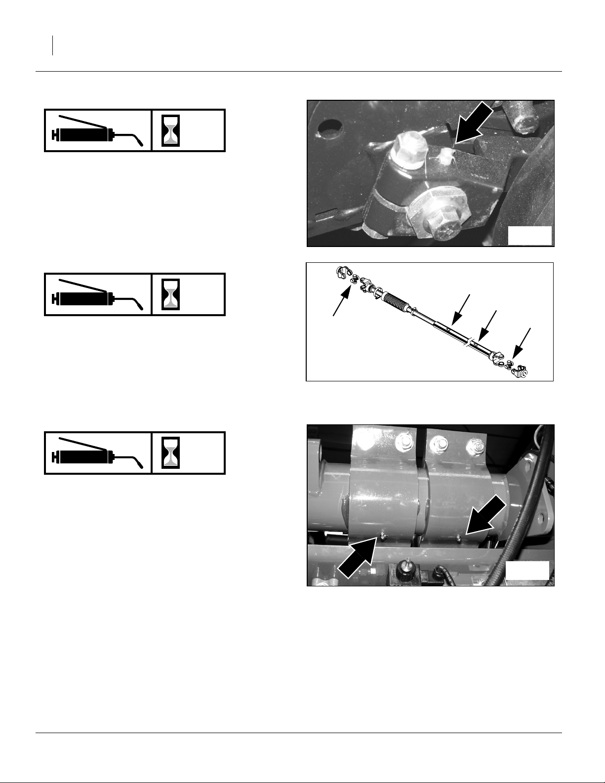
66 YP1220 Great Plains Manufacturing, Inc.
20 Series side wheel bushing
8
2 zerks per row unit;
one each side of each row-unit
Type of Lubrication: Grease
Quantity: Until grease emerges
21960
Wing Transfer Drive Shafts
50
4 zerks each side; 8 total
➁ two each outer shaft sleeve
➀ one each of 2 universal joints
(newer and upgraded models)
Type of lubrication: Grease
Quantity: Until grease emerges (joints)
Quantity: 6 pumps (shafts)
Rockshaft pivot pins
50
Two zerks on top, two on bottom;
four total
Type of Lubrication: Grease
Quantity: Until grease emerges
➀
25280
➁
➁
➀
21957
401-506M 03/14/2012

Great Plains Manufacturing, Inc. Maintenance and Lubrication 67
Main Transport Wheel Bearings
Seasonally
2 bearings each side;
4 total
Type of Lubrication: Grease
Quantity: Re-pack
Note: Tire Replacement:
When replacing main transport tires on a ground
drive planter, Great Plains recommends orienting
the direction of tire rotation contrary to the sidewall
recommendation (this provide maximum drag traction to the ground drive).
Gauge Wheel Bearings
21863
Seasonally
2 bearings each side;
4 total
Type of Lubrication: Grease
Quantity: Re-pack
Note: Tire Replacement:
Direction of gauge wheel rotation is not critical. Do,
however, orient the tires the same on both wings to
equalize rolling resistance.
Marker Disk Hubs
Seasonally
4 bearings; 2 each marker
Type of lubrication: Grease
Quantity = Repack
22751
20332
03/14/2012 401-506M

68 YP1220 Great Plains Manufacturing, Inc.
Meter Drive Chains
As
Required
1 chain each meter
Type of Lubrication: Chain Lube
Quantity = Coat thoroughly
Note: Lubricate chains any time there is a chance of
moisture, and when being stored at the end of the
planting season.
18286
Drive Chains
As
Required
Ground Drive on Seed Cart (not shown)
Wing drive (not shown)
Type of Lubrication: Chain Lube
Quantity: Coat thoroughly
Lubricate chains any time there is a chance of moisture,
and when being stored at the end of the planting season.
Walkboard Pivot
Seasonally
1 zerk
Type of lubrication: Grease
Quantity: Until grease emerges
21959
23263
401-506M 03/14/2012

Great Plains Manufacturing, Inc. Maintenance and Lubrication 69
Seed Lubricants
Null4:
29248
Singulator Plus Meters (all seeds)
Ezee Glide Plus Talc-Graphite Mix
821-069C bucket, 5 gallon (19 liter)
Ezee Glide Plus Lubricant
To maximize performance of Great Plains metering systems, it is imperative to use only “Ezee Glide Plus” lubricant. “Ezee Glide Plus” Talc-Graphite lubricant is
mandatory for all seeds, especially treated or inoculated
seed. Thorough mixing of seed and added lubricant
is required.
Recommended usage:
For clean seeds other than milo and cotton sprinkle
one cup of Ezee Glide Plus Talc per 4 bushels or units
(170 ml per 100 liters) of seed.
For milo and cotton double the application to
one cup (or more) per 2 bu or units (335 ml per 100
liters) of seed.
Adjust this rate as necessary so all seeds become
coated while avoiding an accumulation of lubricant in the
bottom of the hopper.
For seed with excessive treatment, or for humid planting
environments, increase the rate as needed for smooth
meter operation.
Null4:
25477
Finger Pickup Meters
EZ-Slide Graphite Powder
821-042C bottle, 1 pound (450 grams)
821-060C jug, 5 pound (2.3 kg)
For Finger Pick Up Meters Only
Use only approved Graphite Powder available from Great
Plains Mfg. Inc. or Precision Planting to ensure proper
lubrication of finger pickup corn seed meters.
Recommended usage:
For finger pickup meters, add one tablespoon (15 ml) of
graphite for each unit of seed corn (80,000 kernels).
In high humidity conditions, or seeds with heavy seed
treatments, increase the application to two tbsp (30ml).
If delivery of seed from the hopper to the finger meter is
an issue, add “Ezee Glide Plus” talc and graphite blend
at a rate of one cup (237ml) per 4 units of seed. Adjust
until issue is resolved.
Irritation and Chronic Exposure Hazard:
Wear gloves. DO NOT use hands or any part of your body to
mix seed lubricant. Wear a respirator when transferring and
mixing. Avoid breathing lubricant dust. Not an acute hazard.
May cause mechanical eye or skin irritation in high concentrations. As with all mineral spills, minimize dusting during
clean-up. Prolonged inhalation may cause lung injury. Prod-
Irritation and Chronic Exposure Hazard:
Wear gloves. DO NOT use hands or any part of your body to
mix seed lubricant. Wear a respirator when transferring and
mixing. Avoid breathing lubricant dust. Not an acute hazard.
May cause mechanical eye or skin irritation in high concentrations. As with all mineral spills, minimize dusting during
clean-up. Prolonged inhalation may cause lung injury.
uct can become slippery when wet.
03/14/2012 401-506M

70 YP1220 Great Plains Manufacturing, Inc.
Options and Accessories
Hydraulic Tongue
A 3-point hitch is standard on the YP1225 and YP1625,
but a hydraulic tongue may be substituted.
Option Packages Part Number
YP1225/1625 Hydraulic Tongue; Fac-
tory-Installed
YP1225/1625 Hydraulic Tongue;
Field-Installed
401-429A
401-430A
Markers
Markers are a standard factory-installed feature on the
Yield Pro Planter, but may be optionally deleted, for
example, if all planting is done via GPS navigation.
Markers are not trivial to install as a field upgrade. If any
possible future planting might require markers, do not
delete them from the initial Yield Pro Planter order.
For operations, see:
“Marker Operation” on page 32, and
“Marker Adjustments” on page 41.
Auxiliary Hydraulic kit
When the planter is not in motion, these kits enable the
marker hydraulic circuit to be used to drive off-planter
equipment, such as a seed auger.
25231
27292
Option Packages Part Number
YP1225 Auxiliary Hydraulic Kit 401-435A
YP1625 Auxiliary Hydraulic Kit 407-441A
For operation, see “Using Auxiliary Hydraulic Circuit”
on page 26.
25323
401-506M 03/14/2012

Great Plains Manufacturing, Inc. Options and Accessories 71
82bu or 150 bu Seed Hopper
A hopper may be purchased with the Yield Pro Planter or
added later.
Option Packages Part Number
82bu Bulk Hopper (shown) 403-143K
150bu Bulk Hopper 403-174K
The hoppers have no other prerequisites on the planter,
but you will need a means of top-loading seed when the
hopper is mounted on the seed box. Consider ordering
the Auxiliary Hydraulic kit to power an auger.
The 82bu hopper is usually, and the 150bu hopper is
almost always, too heavy too be safely fork-lifted onto the
planter if already pre-loaded with seed.
For operations, see:
“Changing the Seed Box or Hopper” on page 25.
Seed Lubricants
25296
Description Order Number
Ezee Glide Plus Talc + Graphite
(5 gallon container)
FigureSpacer:
821-069C
18.4R42 Tires
Standard YP1220 transport tires are 8 Star 14.9R46
Radial R-1 and 10 bolt rims. When ordered with a new
planter, the following option substitutes 3 Star 18.4R42
R-1 and 10-bolt rims.
Option Packages Part Number
TIRE KIT 18.4-42 FOR YP PLTRS 401-261A
FigureSpacer:
29248
27471
03/14/2012 401-506M

72 YP1220 Great Plains Manufacturing, Inc.
Row Options (Unit-Mount)
Seed Meters
Seed meters are standard in the base Yield Pro Planter
configuration. They do not include a seed wheel.
Meters Part Number
20 Series Singulator Plus, Air 403-255K
27469
20 Series Seed Meter Wheels
Singulator Plus meters accept a variety of seed wheels,
each optimized for specific seeds. Wheels are simple to
change. 20 Series meters use only black seed wheels.
Singulating Wheels
Meter Wheels
Cotton (4000-4600 seeds/lb)
Cotton (4600-5200 seeds/lb)
Cotton (5200-6000 seeds/lb)
Milo (51 cell)
Milo (102 cell)
Milo (135 cell) 12,000-18,000 seeds/lb)
Milo (135 cell, 10,500-14,000 seeds/lb)
Milo (270 cell) 12,000-18,000 seeds/lb)
Milo (270 cell, 10,500-14,000 seeds/lb)
Soybean (1700-2000 seeds/lb)
Soybean (2000-2700 seeds/lb)
Soybean (2700-3200 seeds/lb)
Soybean (3100-3800 seeds/lb)
Soybean (3600-4000 seeds/lb)
Part
Number
403-078D
403-077D
403-076D
403-092D
403-093D
403-081D
403-090D
403-082D
403-091D
403-071D
403-070D
403-061D
403-066D
403-068D
26228
Volumetric Wheels
Meter Wheels
Barley, Oats, Soft Red Wheat (High-Volume)
Rice (Low-rate) Volumetric
FlowGate plus 403-425D wheel
Rice (High-rate Volumetric)
FlowGate plus 403-095D wheel
Rice (Medium-rate Volumetric)
FlowGate plus 403-142D wheel
Wheat (High-rate) Various sizes and varieties (70190 lbs)
Wheat (Volumetric) Various sizes and varieties
(35-145 lbs)
Part
Number
403-094D
403-425D
403-249A
403-095D
403-111A
403-142D
403-125A
403-085D
403-085D
401-506M 03/14/2012

Great Plains Manufacturing, Inc. Options and Accessories 73
Seed-Lok® Seed Firmer
The base Yield Pro Planter includes a seed flap. A
choice of seed firmers is an option in the product bundles, or may be field-installed as kits. Only one type of
seed firmer may be installed at the same time.
Description Part Number
20 Series Seed-Lok® kit
(per opener)
122-268K
For operations, see:
“Seed Firmer Adjustments” on page 47.
Keeton Seed Firmer
The base Yield Pro Planter includes a seed flap. A
choice of seed firmers is an option in the product bundles, or may be field-installed as kits. Only one type of
seed firmer may be installed at the same time.
Description Part Number
Keeton seed firmer (per opener) 494-171S
For operations, see:
“Seed Firmer Adjustments” on page 47.
Row Unit Press Wheels
The base Yield Pro planter includes a choice of press
wheels. Additional wheels are available, and all may be
field-installed.
This manual does not list kit part numbers as the available wheels are often region-specific. Consult your Great
Plains dealer.
For operations, see:
“Press Wheels” on page 48.
20039
20327
19901
03/14/2012 401-506M

74 YP1220 Great Plains Manufacturing, Inc.
Appendix
Specifications and Capacities
YP1220-3510
3 circuits
Hydraulic Requirements
LS Closed or PC Closed
2250 psi, 25 gpm
Hitch
Transport Width
Working Width
Transport Length
Transport Clearance
Transport Height
Weight (Approx.)
Row Spacing (inches)
Number of Openers
Seed Hopper Capacity
Tire Sizes
Opener Travel
Opener Depth Range
Opener Down Pressure
3-point
13ft 6in
30ft
36ft 2in (12 row)
22in
12ft 6in
19285 lbs (8748 kg)
10in (25.4cm)
35
82bu, 150bu or ProBox (box not included)
Transport: 14.9R46 8-Star or 18.4x42 3 Star
Gauge Wheel: 395/55x16.5NHS
Contact Drive: 18x9.50-8 4 Ply
10in
0 to 4in
100-225lb per row
Tire Inflation
Tire Size Inflation
PSI
395/55B 16.5 NHS Skid Steer 60
14.9 x 46 8 Star 30
18.4 x 42 3 Star 18
18 x 9.50-8 4 Ply 12 - 15
20 x 8.00-10 Turf Tire 16
401-506M 03/14/2012
All tires are warranted by the original manufacturer
of the tire. Tire warranty information is found in the
brochures included with your Operator’s and Parts
Manuals or online at the manufacturer’s web sites
listed below. For assistance or information, contact
your nearest Authorized Farm Tire Retailer.
Manufacturer Web site
Titan www.titan-intl.com
Goodyear Now: www.titan-intl.com
Firestone www.firestoneag.com

Great Plains Manufacturing, Inc. Appendix 75
Torque Values Chart
Bolt
Size
in-tpi
1
⁄4-20
1
⁄4-28
5
⁄16-18
5
⁄16-24
3
⁄8-16
3
⁄8-24
7
⁄16-14
7
⁄16-20
1
⁄2-13
1
⁄2-20
9
⁄16-12
9
⁄16-18
5
⁄8-11
5
⁄8-18
3
⁄4-10
3
⁄4-16
7
⁄8-9
7
⁄8-14
1-8
1-12
1
1
⁄8-7
1
1
⁄8-12
1
⁄4-7
1
1
⁄4-12
1
3
⁄8-6
1
3
1
⁄8-12
1
1
⁄2-6
1
1
⁄2-12
Bolt Head Identification
Grade 2 Grade 5 Grade 8 Class 5.8 Class 8.8 Class 10.9
a
b
d
N-m
ft-lb
7.4 11 16
8.5 13 18
15 24 33
17 26 37
27 42 59
31 47 67
43 67 95
49 75 105
66 105 145
75 115 165
95 150 210
105 165 235
130 205 285
150 230 325
235 360 510
260 405 570
225 585 820
250 640 905
340 875 1230
370 955 1350
480 1080 1750
540 1210 1960
680 1520 2460
750 1680 2730
890 1990 3230
1010 2270 3680
1180 2640 4290
1330 2970 4820
N-m N-m
5.6 8 12
61014 5 811
11 17 25 12 19 27
13 19 27 13 21 29
20 31 44 24 39 53
22 35 49 29 45 62
32 49 70 42 67 93
36 55 78 44 70 97
49 76 105 66 77 105
55 85 120 68 105 150
70 110 155 73 115 160
79 120 170 105 165 230
97 150 210 115 180 245
110 170 240 145 230 300
170 265 375 165 260 355
190 295 420 205 325 450
165 430 605 230 480 665
185 475 670 355 560 780
250 645 910 390 610 845
275 705 995 705 1120 1550
355 795 1290 785 1240 1710
395 890 1440 1270 1950 2700
500 1120 1820 1380 2190 3220
555 1240 2010
655 1470 2380
745 1670 2710
870 1950 3160
980 2190 3560
Bolt Head Identification
Bolt
Size
ft-lb ft-lb ft-lb ft-lb ft-lb
mm x pitch
M 5 X 0.8
M 6 X 1
M 8 X 1.25
M 8 X 1
M10 X 1.5
M10 X 0.75
M12 X 1.75
M12 X 1.5
M12 X 1
M14 X 2
M14 X 1.5
M16 X 2
M16 X 1.5
M18 X 2.5
M18 X 1.5
M20 X 2.5
M20 X 1.5
M24 X 3
M24 X 2
M30 X 3.5
M30 X 2
M36 X 3.5
M36 X 2
a. in-tpi = nominal thread diameter in inches-threads per inch
b. N· m = newton-meters
c. mm x pitch = nominal thread diameter in mm x thread pitch
d. ft-lb = foot pounds
c
5.8 8.8 10.9
N-m N-m N-m
357
71115
17 26 36
18 28 39
33 52 72
39 61 85
58 91 125
60 95 130
90 105 145
92 145 200
99 155 215
145 225 315
155 240 335
195 310 405
220 350 485
280 440 610
310 650 900
480 760 1050
525 830 1150
960 1510 2100
1060 1680 2320
1730 2650 3660
1880 2960 4100
946
Torque tolerance + 0%, -15% of torquing values. Unless otherwise specified use torque values listed above.
25199m
25199
03/14/2012 401-506M

76 YP1220 Great Plains Manufacturing, Inc.
Hydraulic System Diagram
21927
401-506M 03/14/2012

Great Plains Manufacturing, Inc. Appendix 77
Chain Routing
Ground Drive
15T
15T
15T
255P
25T
27322
15T
17T
17T
15T
57P
91P
15T
23T
23T
23T
88P
15T
15T
15T
30T
03/14/2012 401-506M

78 YP1220 Great Plains Manufacturing, Inc.
Wing Drive
25T
91P
25T
30T
27346
401-506M 03/14/2012

Great Plains Manufacturing, Inc. Appendix 79
20 Series Meter Drive Chain
12T
1
81P
0
26238
Meter Drive (Front type)
Note: No idlers on mount.
0
1
top chain passes under single idler on shank
2
be sure to reconnect idler spring
19T
19T
3
4
2
12T
26239
124P
Meter Drive (Rear type)
Note: be sure to reconnect idler spring
2
3
top chain passes between 2 idlers at mount
4
top chain passes between 2 idlers at shank
2
03/14/2012 401-506M

80 YP1220 Great Plains Manufacturing, Inc.
Warranty
Warranty
Great Plains Manufacturing, Incorporated warrants to the original purchaser that this seeding equipment will be free from defects in material
and workmanship for a period of one year from the date of original purchase when used as intended and under normal service and conditions
for personal use; 90 days for commercial or rental purposes. This Warranty is limited to the replacement of any defective part by Great Plains
Manufacturing, Incorporated and the installation by the dealer of any
such replacement part. Great Plains reserves the right to inspect any
equipment or part which are claimed to have been defective in material
or workmanship.
This Warranty does not apply to any part or product which in Great
Plains’ judgement shall have been misused or damaged by accident or
lack of normal maintenance or care, or which has been repaired or altered in a way which adversely affects its performance or reliability, or
which has been used for a purpose for which the product is not designed. This Warranty shall not apply if the product is towed at a speed
in excess of 20 miles per hour.
Claims under this Warranty must be made to the dealer which originally
sold the product and all warranty adjustments must by made through
such dealer. Great Plains reserves the right to make changes in materials or design of the product at any time without notice.
This Warranty shall not be interpreted to render Great Plains liable for
damages of any kind, direct, consequential, or contingent, to property.
Furthermore, Great Plains shall not be liable for damages resulting from
any cause beyond its reasonable control. This Warranty does not extend to loss of crops, losses caused by harvest delays or any expense
or loss for labor, supplies, rental machinery or for any other reason.
No other warranty of any kind whatsoever, express or implied, is
made with respect to this sale; and all implied warranties of merchantability and fitness for a particular purpose which exceed
the obligations set forth in this written warranty are hereby disclaimed and excluded from this sale.
This Warranty is not valid unless registered with Great Plains Manufacturing, Incorporated within 10 days from the date of original purchase.
29634
401-506M 03/14/2012

Great Plains Manufacturing, Inc. Index 81
Index
A
address, Great Plains ..................11
adjustment screw ........................41
air leak .........................................34
air system, clean out ...................59
airbox operation ...........................33
alignment .....................................19
alignment, press wheel ................49
amber reflector ..............................7
anchor pin ....................................65
angle, side gauge wheel ..............45
assistance ...................................11
attachments .................................10
auger ...............................26, 70, 71
auxiliary hydraulic ..................26, 32
auxiliary hydraulic kit .............70, 71
axle ..............................................11
B
backing up .............................31, 43
barley ...........................................72
base end ......................................14
black ............................................13
black seed wheels .................46, 72
bleeding hydraulics ................17, 55
blockage ......................................34
blue ........................................13, 14
bulk hopper pins ..........................25
bushing, side gauge wheel ..........45
bushing, side wheel .....................62
butterfly valve ..............................33
C
cab control console .....................30
cab, tractor ............................16, 20
cam ..............................................44
cam, row unit ...............................44
capacities ....................................74
capacity, hoppers ........................29
case drain ..............................14, 33
caster wheel pivot ........................64
caution ...........................................1
chain clip .....................................60
chain maintenance ......................60
chain routing ................................77
chains ..........................................68
changing boxes ...........................25
check for leaks ......................13, 15
checklists
pre-operations .....................21
Pre-Start ..............................12
pre-usage ............................26
chemicals ......................................2
circuits, hydraulic ......................... 14
clean out, air system ...................59
clean out, meter .......................... 56
clean-out door .............................56
clearance .....................................22
clothing .......................................... 2
clutch cable .................................16
clutch lubrication ......................... 31
clutch, electric ............................. 30
clutches ................................. 24, 25
color code ..............................13, 14
contact .........................................11
contact wheel ........................38, 39
continuous flow ........................... 14
corn .............................................33
cotton .................................... 69, 72
crushing hazard .............................7
cylinder symbols .......................... 13
D
danger ........................................... 1
danger decals ................................7
daytime reflector ............................ 7
decal
Crushing Hazard ................... 7
Electrocution Hazard ............. 8
Excessive Speed ...................9
High Pressure Fluid Hazard ..8
Overhead Hazard .................. 8
Pinch/Shear Hazard ..............8
Read Operator Manual ..........9
Tire Pressure .........................9
Tires Not A Step .................... 9
decal installation ............................6
decals ........................................ 1, 6
deeper planting ........................... 44
definitions .................................... 10
depth control ......................... 28, 29
description of unit ........................ 10
DICKEY-john® monitor ...............20
direction, tire rotation ................... 67
disconnecting hydraulic lines 13, 15
disk angle, marker ....................... 42
disk blade .................................... 62
disk blades ..................................61
disk spreader ...............................61
door, clean-out ............................56
down pressure, contact wheel ..... 39
down pressure, press wheel ....... 48
draw bar ...................................... 15
drive shaft ................................... 30
drive shafts, transfer ................... 66
DRIVEN sprocket ........................ 38
DRIVING sprocket ...................... 38
E
electric clutch .............................. 30
electric clutch lockup ................... 31
electrocution hazard ...................... 8
electro-hydraulic control valve .... 20
emergency .................................... 1
eye-bolt ....................................... 18
Ezee Glide Plus .................... 69, 71
F
fan ................................... 13, 14, 59
fan motor ..................................... 14
fan rpm ........................................ 29
fan speed .................................... 33
field operation ............................. 29
fire ................................................. 1
Firestone ..................................... 74
Flow Gate .............................. 58, 59
fold circuit .............................. 13, 14
fold hydraulics, bleeding ............. 55
folding planter ............................. 22
folding speed, markers ................ 41
fork lift ......................................... 25
frame leveling .............................. 17
G
gates, Y-tube ............................... 59
gauge wheel .......................... 18, 67
gauge wheels .............................. 23
Goodyear .................................... 74
graphite ................................. 33, 71
graphite lubricant ........................ 26
graphite powder .......................... 69
green ........................................... 13
H
handle, seed depth ..................... 44
harness ....................................... 16
hazard ........................................... 1
headphones .................................. 2
hearing protection ......................... 2
height, tongue ............................. 16
hex adjuster ................................ 45
hex adjustment, side wheel ......... 62
high pressure fluid ......................... 8
high pressure fluids ....................... 2
03/14/2012 401-506M

82 YP1220 Great Plains Manufacturing, Inc.
hitch ................................ 22, 24, 70
hitch, 3-point ............................... 15
hitching ........................................ 15
hitching, hydraulic tongue ........... 15
holding pin ................................... 16
hooks, transport .................... 22, 24
hooks, wing ........................... 22, 24
hopper ............................. 25, 33, 71
hopper pins ................................. 25
hopper sensor ............................. 29
hoses, hydraulic .................... 13, 14
humidity ....................................... 69
hydraulic charge .......................... 17
hydraulic circuit ........................... 14
hydraulic flow .............................. 33
hydraulic hoses ..................... 13, 14
hydraulic leaks .............................. 2
hydraulic motor seals .................. 14
hydraulic system diagram ........... 76
hydraulic tongue .......................... 70
hydraulic tongue hitch ................. 15
hydraulic, aux .............................. 70
hydraulic, bleeding ...................... 17
I
Important, about .......................... 10
inflating tires .................................. 4
inflation ........................................ 74
injury ............................................. 2
inoculated seed ........................... 26
inspection, meter ......................... 47
intended usage ........................... 10
J
JIC ............................................... 55
Joint Industry Conference ........... 55
K
Keeton seed firmer ................ 47, 73
L
ladder .......................................... 26
leak checks ........................... 13, 15
leak, air ....................................... 34
leaks ........................................ 2, 55
left-hand ...................................... 10
level ....................................... 16, 18
level sensor ................................. 33
leveling frame .............................. 17
lift ................................................ 22
lift circuit ................................ 13, 14
lift cylinder lock ............................ 23
lift hydraulics, bleeding ................ 55
light cable .................................... 16
lights ........................................ 3, 28
load control ................................. 29
loading seed ............................... 25
location
model number ..................... 11
serial number ...................... 11
lock
lift cylinder ........................... 23
transport cylinder ................ 23
lock channels ........................ 23, 28
lock pins, seed frame .................. 25
lock storage ................................ 23
lockup channels .......................... 35
lock-up Seed-Lok™ .................... 48
lockup, electric clutch .................. 31
low pressure return ..................... 14
lubricant ...................................... 26
lubricant, seed ............................ 69
lubrication ................................... 64
lubrication, clutch ........................ 31
M
maintenance ........................... 4, 54
manifold ...................................... 59
manual, about ............................. 10
mark width .................................. 42
marker ............. 8, 25, 26, 63, 64, 67
marker adjustments .................... 41
marker circuit ........................ 13, 14
marker extension ........................ 41
marker hydraulics, bleeding ........ 55
marker operation ......................... 32
marker speed .............................. 41
marker width ............................... 41
markers ................................. 28, 70
medical assistance ....................... 2
meter clean out ........................... 56
meter slide .................................. 58
meter wheel, installing ................ 47
milo ....................................... 69, 72
model number (yours) ................. 11
modifications ............................... 10
monitor ........................................ 16
monitor mounting plate ............... 20
monitor operation ........................ 30
motor seals ........................... 14, 33
mounting plate ............................ 20
M8-1.25x14mm ........................... 31
N
National Pipe Thread .................. 55
Note, about ................................. 10
NPT ............................................. 55
O
oats ............................................. 72
opener side wheel ....................... 62
operating ......................................21
options ...................................10, 70
orange .........................................14
ORB .............................................55
O-Ring Boss ................................55
overhead power lines ....................3
P
paint .............................................36
parallel arms ................................43
parallel pivot arms .......................64
parking .........................................35
parking stand .........................16, 35
pickup sensor ..............................30
pickup wheel ................................30
planting depth ..............................44
planting rate .................................38
plastic sealant tape ......................55
pockets, meter wheel ...................46
point row monitor .........................20
power-beyond port .......................14
precision meter ......................26, 56
preparation ..................................12
press wheel .................................49
press wheel alignment .................49
press wheel stagger ....................48
press wheels ....................43, 48, 73
prop stands ..................................35
protective clothing ..........................2
PSI ...............................................74
public roads .................................28
Q
QD ...............................................55
Quick Disconnect .........................55
quick-connect ports .....................26
R
range sprockets ...........................38
red reflector ...................................6
reflectors ....................................3, 6
amber .....................................7
daytime ..................................7
red ..........................................6
SMV .......................................6
remote valve ..........................13, 14
repair ...........................................11
re-phase ......................................17
re-phase cylinders .......................32
re-phasing ..............................17, 24
re-phasing fold system ................32
re-phasing lift system ...................32
replacement, tires ........................67
retaining pin, clean-out ................56
retaining ring, hose ......................56
401-506M 03/14/2012

Great Plains Manufacturing, Inc. Index 83
rice ...................................58, 59, 72
riders .............................................2
right-hand ....................................10
roads .............................................3
rockshaft pivot pins ......................66
rod end ........................................14
rod, contact wheel .......................39
rotation, direction .........................67
rough terrain ..................................3
row-unit adjustments ...................43
row-unit down pressure ...............44
S
safety decals .................................6
safety information ..........................1
safety symbol ................................1
seed auger ..................................70
seed box ......................................25
seed box pins ..............................25
seed firmer ..................................43
seed firmers ...........................47, 73
seed flap ......................................43
seed hose, retaining ring .............56
seed lubricant ..............................69
seed lubricants ......................69, 71
seed meter ..................................43
seed meter timing ........................39
seed meter wheel ........................56
seed meters .................................72
seed trench ..................................49
seed tube .....................................43
seed, treated .................................2
Seed-Lok® ..................................73
Seed-Lok™ .................................48
selector switch .......................22, 24
sensor, hopper ............................29
sensor, pickup .............................30
sequence valve .....................32, 41
serial number (yours) ..................11
setup ............................................12
shallower planting ........................44
shank, side gauge wheel .............45
shim .............................................61
shims, side wheel ........................62
shutdown .......................................3
side depth wheels ........................44
side gauge wheels .......................45
side wheel bushing ......................66
side wheels, opener ....................62
signal words ..................................1
CAUTION ..............................1
DANGER ...............................1
WARNING .............................1
singulating wheels ....................... 72
Singulator Plus ............................ 72
slack ...................................... 38, 60
slide gate ............................... 25, 26
slide roller .................................... 65
slide, meter ..................................47
sliding door .................................. 59
Slow Moving Vehicle ..................... 6
SMV (Slow Moving Vehicle) ..........6
soybean .......................................72
spacer ................................... 49, 61
specifications ...............................74
speed limit ..................................... 3
spreader ...................................... 61
spring, contact wheel .................. 39
spring, press wheel .....................48
stagger ........................................49
stagger, press wheel ................... 48
sticky conditions .......................... 48
sticky treatments .........................34
storage ..........................................3
sump return ................................. 33
sway blocks ................................. 15
symbol, safety ...............................1
T
tables
adjustments ......................... 37
airbox troubleshooting ......... 34
capacities ............................ 74
fan speed ............................. 42
fan speeds ...........................29
hose color code ............. 13, 14
models covered ................... 10
specifications .......................74
tire inflation .......................... 74
torque values .......................75
troubleshooting ....................50
talc .........................................34, 71
talc lubricant ................................ 26
talc-graphite lubricant .................. 69
tape, pipe .................................... 55
T-handle ................................ 43, 44
timing, seed meter ....................... 39
tire replacement .......................... 67
tire rotation direction .................... 67
tire, side wheel ............................62
tires ............................... 4, 9, 71, 74
Titan ............................................74
tongue circuit ......................... 13, 14
tongue height .............................. 16
tongue lift cylinder .......................65
tool bar pivot ................................65
top link ......................................... 16
torque values .............................. 75
tractor cab ................................... 16
transfer drive shafts .................... 66
transmission sprockets ............... 38
transport ........................................ 3
transport hooks ..................... 22, 24
transport lock .............................. 23
transport lock channels ............... 25
transport tires .............................. 67
transporting ................................. 28
treated seed .................................. 2
troubleshooting, airbox ................ 34
U
unfolding planter ......................... 24
URLs, tires .................................. 74
V
vent line update ........................... 33
volumetric wheels ....................... 72
W
walkboard ................................ 6, 25
walkboard pivot ........................... 68
warning ......................................... 1
warning decals .............................. 8
warranty ................................ 41, 80
weight
towing vehicle ........................ 3
welding .......................................... 4
wheat .......................................... 72
wheel bearings ............................ 67
wheel retainer ............................. 46
wheel, seed meter ................. 46, 56
wheels, singulating ...................... 72
wheels, volumetric ...................... 72
white ............................................ 14
wing alignment ............................ 19
wing hooks ............................ 22, 24
wing locks ................................... 28
wings ............................... 18, 22, 24
Y
Yield-Pro ..................................... 10
YP1220-3510 ........................ 10, 11
YP1220-3510, described ............ 10
Y-tube ......................................... 33
Y-tubes ........................................ 59
Numerics
102 cell ........................................ 72
122-268K, Seed-Lok ................... 73
135 cell ........................................ 72
14.9R46 ...................................... 71
14.9R46 8-Star ............................ 74
14mm length bolts ....................... 31
03/14/2012 401-506M

84 YP1220 Great Plains Manufacturing, Inc.
150 bu ................. 29, 33, 42, 71, 74
18.4R42 ...................................... 71
18.4x42 3 Star ............................. 74
18x9.50-8 4 Ply ........................... 74
20 mph ...................................... 3, 9
20 Series ..................................... 10
20-30 range................................. 42
25 Series row unit ....................... 43
26in ............................................. 18
270 cell ........................................ 72
3-Point Hitch ............................... 15
3-point stands ............................. 35
3000 rpm ............................... 33, 42
3000-4500 rpm ...................... 33, 42
32 kph ........................................... 3
3500 rpm ......................... 29, 33, 42
37 degree flare ............................ 55
3800 rpm ......................... 29, 33, 42
395/55x16.5NHS ......................... 74
401-261A, tires ............................ 71
401-429A, hydraulic tongue ........ 70
401-430A, hydraulic tongue ........ 70
401-435A, aux. hydraulic ............ 70
401-506B, seed rate manual ....... 10
401-506M, this manual ............... 10
401-506P, parts manual .............. 10
403-061D, seed wheel ................ 72
403-066D, seed wheel ................ 72
403-068D, seed wheel ................ 72
403-070D, seed wheel ................ 72
403-071D, seed wheel ................ 72
403-076D, seed wheel ................ 72
403-077D, seed wheel ................ 72
403-078D, seed wheel ................ 72
403-081D, seed wheel ................ 72
403-082D, seed wheel ................ 72
403-085D, seed wheel ................ 72
403-090D, seed wheel ................ 72
403-091D, seed wheel ................ 72
403-092D, seed wheel ................ 72
403-093D, seed wheel ................ 72
403-094D, seed wheel ................ 72
403-095D, seed wheel ................ 72
403-111A, Flowgate +wheel ....... 72
403-125A, FlowGate + wheel ..... 72
403-142D, seed wheel ................ 72
403-143K, 82bu hopper .............. 71
403-174K, 150bu hopper ............ 71
403-249A, flow gate + wheel ...... 72
403-255K, seed meter ................ 72
403-425D, seed wheel ................ 72
407-441, aux. hydraulic .............. 70
4500 rpm ...............................33, 42
46in ..................................16, 18, 29
494-171S, Keeton ........................73
51 cell ..........................................72
8 - 12 gpm ...................................33
802-130C, shear bolt ...................63
817-348C, hose label ..................14
817-405C, meter slide .................58
817-529C, Flow Gate ..................59
818-055C, decal ............................6
818-188C, decal ............................9
818-339C, decal ............................8
818-398C, decal ............................9
818-579C, decal ............................8
818-580C, decal ............................8
818-590C, decal ............................7
82 bu ...................29, 33, 42, 71, 74
821-042C, graphite ......................69
821-060C, graphite ......................69
821-069C, graphite+talc ..............69
821-069C, lubricant .....................71
838-265C, decal ............................7
838-266C, decal ............................6
838-267C, decal ............................7
838-599C, decal ............................8
838-995C, decal ............................9
401-506M 03/14/2012

BLANK

EOD
Great Plains Manufacturing, Inc.
Corporate Office: P.O. Box 5060
Salina, Kansas 67402-5060 USA
 Loading...