

Page 1
Part Lists Great Plains Manufacturing, Inc. 1
Yield-Pro®Planter 1.6 Bu. Hopper Enhancement
Null4:
Used with YP425/625/825A Planters:
• YP425A s/n B1012N-
• YP625A s/n B1057Q-
• YP825A s/n B1016S-
• YP3P425A s/n B1006M-
• YP3P625A s/n B1008P-
• YP3P825A s/n B1013R-
Null4:
General Information
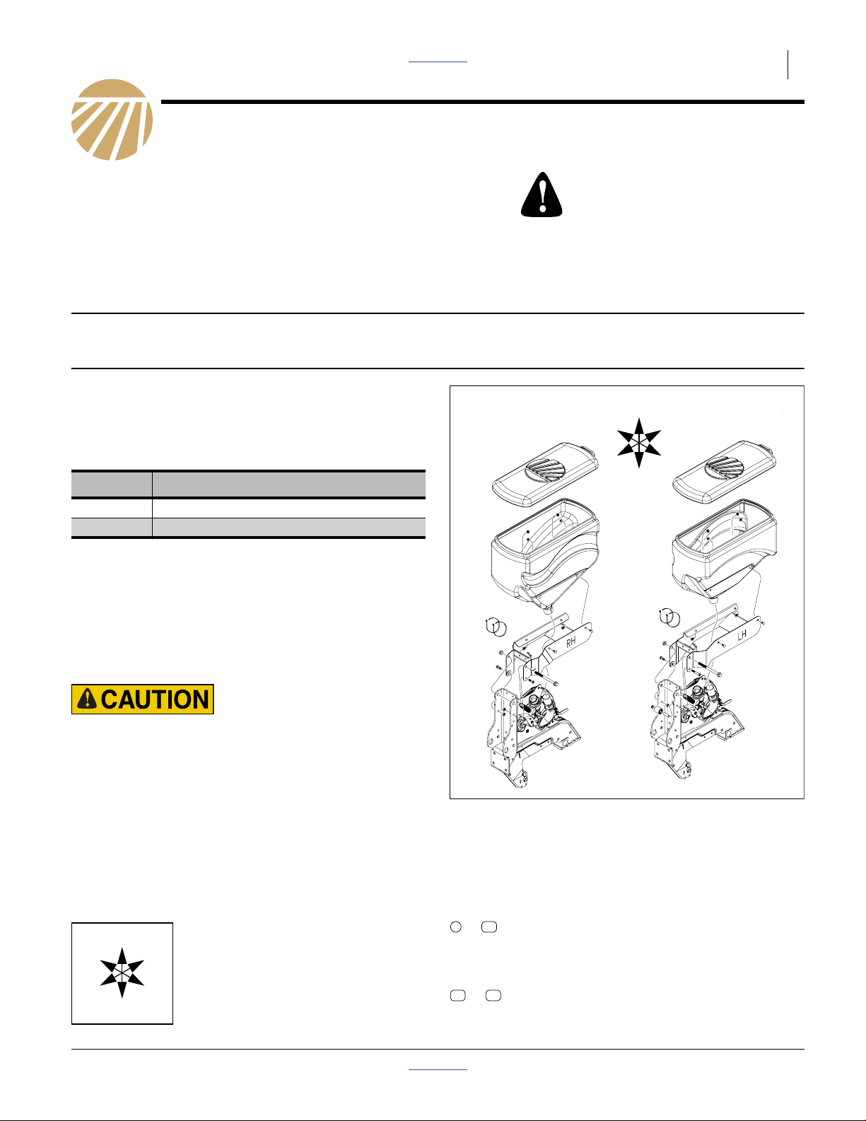
These instructions explain how to install a Yield-Pro®1.6
bushel hopper enhancement. One kit is required per
each planter hopper, either right hand or left hand. (This
enhancement is for planters prior to July 2011 that have
the lesser capacity 1 bu. hoppers.)
Kit Kit Description
403-609A RH 1.6BU HOPPER FLD KIT
403-610A LH 1.6BU HOPPER FLD KIT
Tools Required
• basic hand tools
• support stands
When you see this symbol, the subsequent instructions and warnings are serious - follow without exception. Your life
and the lives of others depend on it!
U
R
F
B
L
D
Work Location
Move the implement to a flat location for installation.
Crushing and Sharp Object hazards:
Be careful working near openers. Discs and other parts may
be sharp.
Notations and Conventions
Null4:
U
F
L
D
“Left” and “Right” are facing in the
direction of machine travel. An orienta-
R
tion rose in the line art illustrations
shows the directions of Left, Right,
Front, Back, Up, Down.
B
Call-Outs
110
to
11 21
to
Figure 1
Right Hand and Left Hand
Hopper Enhancement Kits
Single-digit callouts identify components in
the currently referenced Figure. These numbers may be reused for different items from
page to page.
Two-digit callouts in the range 11 to 21 reference new parts from the list on page 5.
32233
© Copyright 2011 Printed 08/16/2011 Part Lists 403-612M
Page 2
2 Great Plains Manufacturing, Inc. Front Page Part Lists YP 1.6 Bu Hopper Enhancement
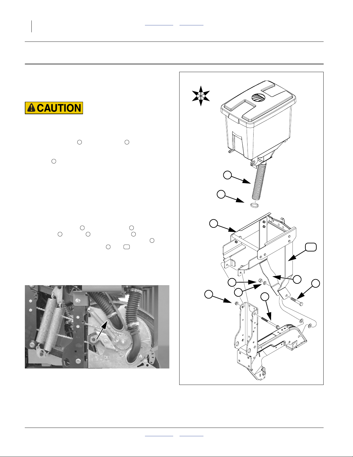
Remove Old Hopper
Refer to Figure 2
Before beginning, raise machine up in air at a sufficient
angle so springs are relaxed with no tension remaining
on the parallel arms. Support with stands.
Crushing Hazard:
Do not work around heavy equipment without support stands
appropriate to the amount of weight they must bear.
1. Remove clamp at base of hose on the old hopper.
This releases the hopper and all parts above
2
hose as one unit. Discard all parts, they will not
be reused.
2. Disconnect the air inlet hose from the seed meter by
removing its clamp (see photo below). Save the
clamp for later assembly.
3. If a blockage monitor is present, disconnect the wire
leading to it by removing the zip tie holding it in
place. (Do this at the same time as disconnecting
the other hoses.)
4. Remove hex nut and 65⁄8inch bolt , also remove
hex nut , washer and 4 inch bolt .
This releases the hopper support weldment and
RH and LH hopper braces and from the
opener arm.
5 6 7
1 2
3 4
8
910
R
F
U
B
L
D
2
1
8
10
Discard the hopper support weldment and braces.
Retain the opener arm.
5
3
6
Figure 2
Remove Old Hopper
4
9
7
32233
403-612M Front Page Part Lists 08/16/2011
Page 3

Install New Right Hand Hopper Front Page Part Lists Great Plains Manufacturing, Inc. 3
Install New Right Hand Hopper
Refer to Figure 3
The right hand and left hand opener mounts are offset.
Be sure the placement is correct for right/left offset orientation.
R
U
B
Install Hopper Support Mount
5. Select:
12
1 403-565H RH HOPPER MOUNT WLDMNT
18
2 802-017C HHCS 3/8-16X1 GR5
19
1 802-323C HHCS 1/2-13X6 1/2 GR5
20
1 803-169C HEX FLGLOCK 1/2-13 PLT
21
2 803-209C FLANGE LOCK 3/8-16 PLT
Secure mount to opener arm bracket using bolt
and nut , just below this hardware insert bolts
and flange locks . Tighten.
20 18
21
Place Hopper on Mount
6. Select:
13
1 403-594K HOPPER ASSEMBLY RH
31
4 802-092C RHSNB 5/16-18X3/4 GR5
32
4 803-177C NUT HEX FLG TP LK 5/16-18ZNYCR
Place new 1.6 bu hopper on hopper mount
and adjoin bottom opening to seed tube. Secure
hopper to mount with four carriage bolts and
32
nuts .
13 12
Connect Meter Air Hose
7. Select one:
16
800-060C CABLE TIE .19X14.25 3DIA 50
31
19
F
16
17
20
D
13
L
32
31
98
99
12
19
Route the air hose through the top left hand corner
of the mount and reconnect it to the air inlet elbow
on the tube meter securing with the clamp saved
earlier.
8. Secure the air hose to the tab mount with the
cable tie .
16
99
18
18
21
21
Connect Blockage Monitor Wire
9. Select one:
17
800-112C CABLE TIE .19X7.25 1.75D 50
Route the blockage monitor cable through the hole
in the front of the mount and reconnect to the
harness. Secure the cable to the mount with
cable tie through hole in the mount and
opener.
08/16/2011 Front Page Part Lists 403-612M
17 98
12
12
Figure 3
Right Hand Hopper
32233
Page 4

4 Great Plains Manufacturing, Inc. Front Page Part Lists YP 1.6 Bu Hopper Enhancement
Install New Left Hand Hopper
Refer to Figure 4
The right hand and left hand opener mounts are offset.
Be sure the placement is correct for right/left offset orientation.
The left hand mount has a 3/8in bolt that is reused
(from the existing assembly). It attaches the idler spool
on the bracket.
23
Install Hopper Support Mount
10. Select:
14
1 403-564H LH HOPPER MOUNT WLDMNT
18
1 802-017C HHCS 3/8-16X1 GR5
19
1 802-323C HHCS 1/2-13X6 1/2 GR5
20
1 803-169C HEX FLG LOCK 1/2-13 PLT
21
2 803-209C FLANGE LOCK 3/8-16 PLT
R
F
U
B
L
D
32
15
Secure mount to opener arm bracket using bolt
and nut .
Just below this hardware insert ildler spacer
tube , idler spool , and secure with saved bolt
23 21
bolt and flange lock . Tighten.
20
25 24
and flange lock . On opposite side insert
18 21
Place Hopper on Mount
11. Select one each:
15
1 403-595K HOPPER ASSEMBLY LH
31
4 802-092C RHSNB 5/16-18X3/4 GR5
32
4 803-177C NUT HEX FLG TP LK 5/16-18ZNYCR
Place new 1.6 bu hopper on hopper mount
and adjoin bottom opening to seed hose. Secure
hopper to mount with four carriage bolts and four
32
nuts .
15 14
Connect Meter Air Hose
12. Select one:
16
800-060C CABLE TIE .19X14.25 3DIA 50
Route the air hose through the top left hand corner
of the mount and reconnect it to the air inlet elbow
on the tube meter securing with the clamp saved
earlier. Secure the air hose to the tab mount with
the cable tie .
16
Connect Blockage Monitor Wire
13. Select one:
17
800-112C CABLE TIE .19X7.25 1.75D 50
Route the blockage monitor cable through the hole
in the front of the mount and reconnect to the
harness. Secure the cable to the mount with
cable tie through hole in the mount and
opener.
17 98
14
31
14
99
19
20
18
21
21
17
24
16
25
23
Figure 4
Left Hand Hopper
31
14
19
32233
403-612M Front Page Part Lists 08/16/2011
Page 5

Appendix Front Page Part Lists Great Plains Manufacturing, Inc. 5
Appendix
Part Lists
New Parts
The part call-out numbers in this list match all Figures in
these installation instructions. Part descriptions match
those in your updated Parts Manual.
Quantities are units (“ea”).
Kit Contents
403-609A RH 1.6BU HOPPER FLD KIT
403-610A LH 1.6BU HOPPER FLD KIT
Quantity in Kit:
Callout 403-609A 403-610A Part Number Part Description
11 1 1 403-612M MANUAL 1.6 BU HOPPER ENHANCEMENT
12 1 0 403-565H RH HOPPER MOUNT WLDMNT
13 1 0 403-594K HOPPER ASSEMBLY RH
14 0 1 403-564H LH HOPPER MOUNT WLDMNT
15 0 1 403-595K HOPPER ASSEMBLY LH
16 1 1 800-060C CABLE TIE .19X14.25 3DIA 50
17 1 1 800-112C CABLE TIE .19X7.25 1.75D 50
18 2 2 802-017C HHCS 3/8-16X1 GR5
19 1 1 802-323C HHCS 1/2-13X6 1/2 GR5
20 1 1 803-169C HEX FLG LOCK 1/2-13 PLT
21 2 2 803-209C FLANGE LOCK 3/8-16 PLT
Other Parts
The part call-out numbers in this list match all Figures in
these installation instructions. Part descriptions match
those in your updated Parts Manual.
Callout Quantity Part Number Part Description
31 4 802-092C RHSNB 5/16-18X3/4 GR5
32 4 803-177C NUT HEX FLG TP LK 5/16-18ZNYCR
08/16/2011 Front Page Part Lists 403-612M
Page 6

6 Front Page Part Lists
Great Plains Manufacturing, Inc.
Corporate Office P.O. Box 5060
Salina, Kansas 67402-5060 USA
403-612M Front Page Part Lists 08/16/2011
 Loading...