

Page 1
Great Plains Mfg., Inc.
Update Instructions
2004 Yield-Pro® 1625 Planter
Base Update 2005 Kit
Used with:
• 2004 Yield-Pro® 1625 Planter
General Information
When you see this symbol, the subsequent instructions and
warnings are serious - follow without exception. Your life and
!
!
the lives of others depend on it!
These instructions explain how to install the 2004 YieldPro® 1625 Planter Base Update 2005 Kit. Field Update
Kits are designed to improve the performance and reliability of the planter.This update includes Yield-Pro® support
stands, new heavy duty gauge wheel casters, replacement idlers, and airbox modifications.
These instructions apply to:
402-187A 2004 Yield-Pro® 1625 Planter Base
Update 2005 Kit
402-180A Yield-Pro® 1625 Fertilizer Update Kit
2005
Assembly Instructions for 402-187A
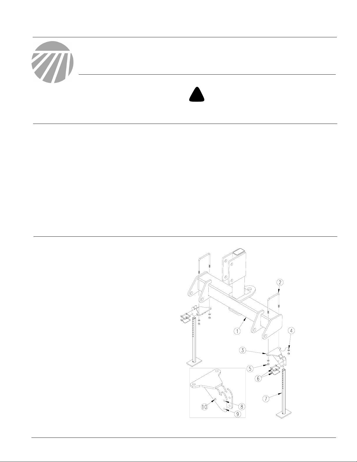
Install Yield-Pro® Support Stand
Refer to Figure 1
1. Attach park stand mount (3) to underside
of hitch crossbar weldment (1) on each
end of crossbar. Secure mount (3) to
crossbar (1) using 1/2-13 x 6 1/32 x 7 1/4
u-bolt (2), 1/2 lock washer (4), and 1/2-13
hex nut (5).
Before You Start
Starting on page 11 is a detailed listing of parts included in
the 2004 Yield-Pro® 1625 Planter Base Update 2005 Kit.
Use this list to inventory parts received.
Tools Required
• Basic Hand Tools
• Snap Ring Pliers
• Caulk Gun
• 2-ton Support Stand and Blocks
• Dial Type Inch-lb Torque Wrench
• Forklift
2. When in use, secure stand (7) to mount
(3) by inserting two 3/8 x 2 1/2 wire snap
lock pins (6) in the two outermost holes (8
and 9) on mount (3).
3. When stand (7) is not in use, remove bottom pin (6) from lower hole (9). Swing
stand underneath crossbar (1) and secure by inserting pin (6) below stand in innermost hole (10) on mount (3).
© Copyright 2005 Printed
12/12/2005
23402
Figure 1
Support Stand
402-188M
Page 2
Base Update 2005 Kit
2
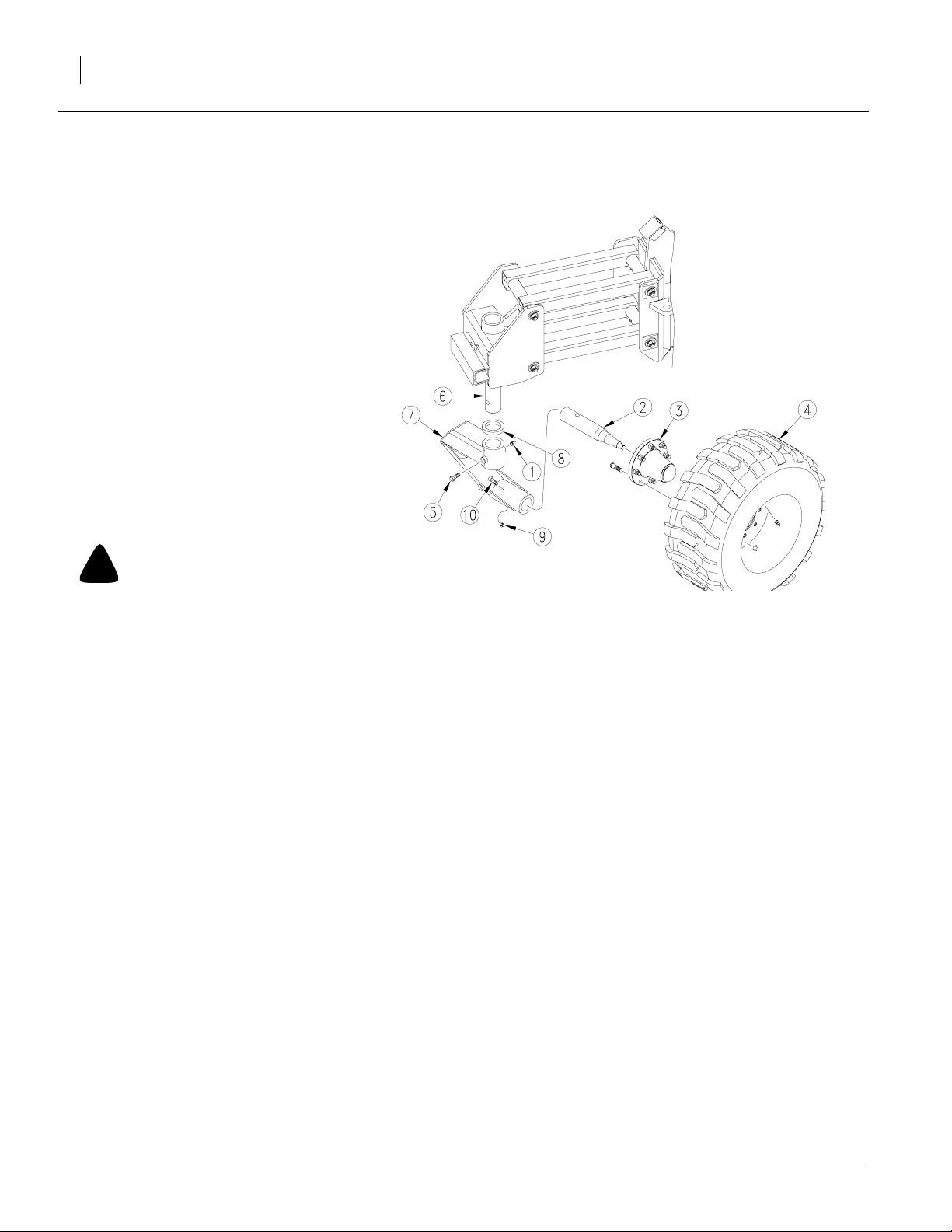
Replace Gauge Wheel Caster and AntiRotate Pins
Refer to Figure 2
NOTE: To replace gauge wheel caster and
and anti-rotate pins, the gauge wheels
will need to be blocked up so the weight
is off the tires. Blocks should have a minimum support capacity of 4 tons.
1. Once unit is blocked up and weight is off
tires, remove tire (4) from hub (3). Remove bolt (10) and lock nut (9) securing
spindle to caster. Slide spindle (2) and
hub (3) out of caster (7).
2. Remove bolt (5) and lock nut (1) securing vertical shaft caster (6) to caster (7).
Caster (7) and pivot thrust washer (8)
should fall to ground. Discard caster (7).
Keep pivot thrust washer (8) for reuse.
Great Plains Mfg., Inc.
!
To avoid injury, use extreme caution when removing caster (7) from vertical shaft (6). Caster
(7) is heavy and will fall once bolt (5) is removed.
3. Replace old caster (7) with new more
4. Reattach spindle (2) and hub (3) to cast-
5. Repeat steps 1 - 4 on opposite side of
CAUTION!
sturdy caster provided in kit. Attach caster and washer (8) removed in step 2 to
vertical shaft caster (6) with bolt (5) and
lock nut (1) removed in step 2.
er (7) with bolt (10) and lock nut (9) removed in step 1. Replace tire (4) on hub
(3) with tire tread in same direction as
before. NOTE: Center of tire will align
below center of pin (6). Tire should
not sit off to one side. Tighten all bolts.
planter.
23403
Figure 2
Replace Gauge Wheel Caster
402-188M 12/12/2005
Page 3
Great Plains Mfg., Inc.
Refer to Figure 3
1. Remove cotter pin and cylinder pin securing hydraulic cylinder to eyebolt weldment. Discard cylinder pin.
2. Remove cotter pin and cylinder pin securing opposite end of hydraulic cylinder to lower swivel
caster weldment. Discard cylinder pin.
3. Reattach cylinder to eyebolt weldment and lower
swivel caster using new cylinder pins provided in
kit. Secure cylinder pins with cotter pins previously removed.
NOTE: When installing new cylinder pins to reattach cylinders, note location of grease outlet
holes in center of pins. Install pins so that holes
are pointing upwards or towards the cylinder
main body.
4. Repeat steps 1-3 on opposite side of planter.
5. Remove blocks supporting planter.
Installation Instructions
3
12/12/2005
24004
Figure 3
Install Anti-Rotating Pins
402-188M
Page 4
Base Update 2005 Kit
4
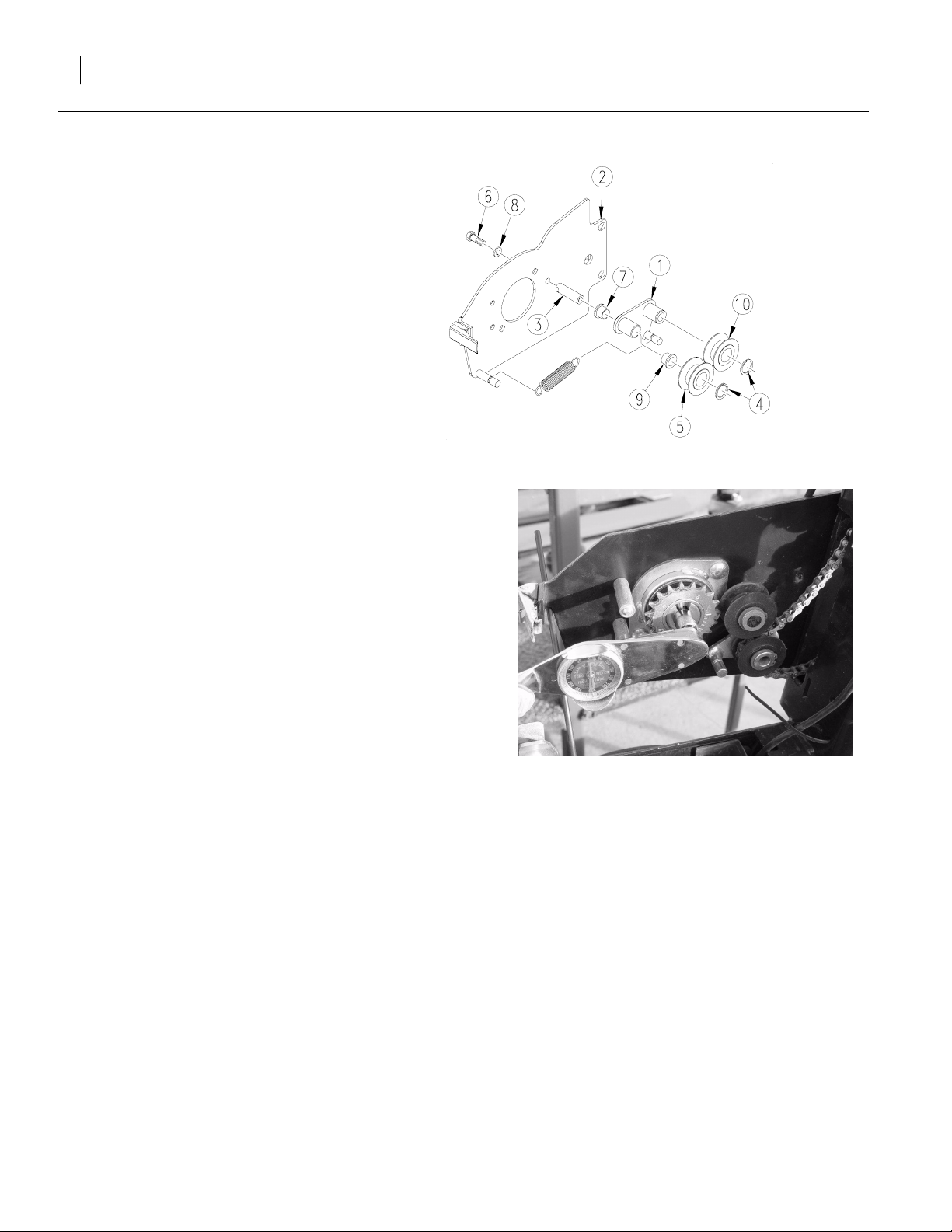
Replace Idlers
Refer to Figure 4
1. Detach meter from opener and set meter aside.
NOTE: It is not necessary to detach hose
from meter.
2. Detach spring from idler bracket weldment. Remove snap ring (4) from front idler (10). NOTE: It
is not necessary to remove both snap rings.
Discard snap ring (4). Keep spring for reuse.
NOTE: If meter drive units have been timed for
staggered drop on twin row spaced planters, do
not remove drive chain from sprocket without
first noting which sprocket tooth is up. Check
that sprocket is timed with same tooth up when
chain is reinstalled or re-time meters when finished according to the instructions in operator’s
manual.
3. On backside of drive mount weldment (2), remove bolt (6) and washer (8) securing idler pivot
(3) and idler bracket weldment (1) to drive mount
weldment (2). Keep bolt (6) and washer (8) for
reuse.
Great Plains Mfg., Inc.
23405
4. Remove idlers (5 and 10), bushings (7 and 9),
idler bracket weldment (1), and idler pivot (3).
Discard idlers (5 and 10), bushings (7 and 9),
idler bracket weldment (1), and idler pivot (3).
5. Turn sprocket by hand for two rotations. Insert
meter drive adapter tool into hub of sprocket.
NOTE: To test torque, remove chain from
sprocket. Complete test with parts at temperatures of 65 degrees or higher. Using 5/8"
socket and an inch-lb torque wrench, measure
drive torque by rotating sprocket in normal direction of travel.
NOTE: Meter drive units with torque readings in
excess of 10 inch-lbs should be replaced. Units
with torque variation, as sprocket is rotated,
greater than 3 inch-lbs should be replaced. Order assmebly 403-117s, one per row as needed.
NOTE: It is not necessary to completely remove
chain from row unit while replacing idlers.
6. Secure idler pivot (3) and bushing (9) to drive
mount weldment using bolt (6) and washer (8)
removed in step 2.
NOTE: DO NOT apply any lubricant or anti-sieze
compounds to these parts when reassembling.
7. Attach idler bracket weldment (1) to idler pivot
(3). Route chain through idlers (5 and 10) as
idlers (5 and 10) are reassembled.
23406
Figure 4
Idler Assembly
8. Place idlers (5 and 10) on idler bracket weldment. Secure idlers (5 and 10 ) to idler bracket
weldment (1) with snap rings (4).
9. Reattach spring to idler bracket weldment (1)
and replace meter.
10. Repeat steps 1-9 for all other openers.
11. Check meter timing on twin row spaced planters.
402-188M 12/12/2005
Page 5

Great Plains Mfg., Inc.
Install Hopper Water Guard Weldment
Refer to Figure 5
1. Be sure hopper is empty. Remove hopper assembly from planter frame and support securely.
NOTE: Before removing parts to install hopper
water guard weldment, mark line on door guide
along bottom of plastic hopper to note door
height. This ensures door is replaced at same
height.
2. Unscrew stop bolt (4). Remove door (3) from
door guide (6). Keep stop bolt (4) and door (3)
for reuse.
3. Remove the two side bolts (7) on both sides of
hopper (1). NOTE: Do not remove bolts se-
curing door guide to front or back of hopper.
Keep removed bolts (7), flat washers, and hex
lock nuts for reuse.
4. Slide water guard (5) all the way up on hopper
(1). Use bolts (7) from step 3 to attach weldment (5) to hopper (1). NOTE: Hopper Water
Guard Weldment attaches to hopper with
double bevelled rain gutter oriented to rear
over door. Other three edges will slope
downward.
Installation Instructions
NOTE: Hopper shown removed from frame for clarity
only. Do not remove hopper from frame.
Figure 5
Hopper Water Guard Weldment
23409
5
5. Using line marked on door guide (6), replace
door (3) at same height as before. Tighten all
bolts.
6. Apply a layer of silicon around joint between
hopper (1) and guard (5).
Important! It is important that guard be sealed completely to hopper to avoid getting water into seed
manifold.
Update Manifold
1. Disconnect level sensor from harness.
Refer to Figure 6
NOTE: Before removing top of manifold, measure distance
from top of meter top seal (A) to top of angle on manifold (B).
Record this dimension to use when reassembling manifold.
Refer to Figure 7
2. Remove bolts (1) securing top manifold weldment (3) to
manifold . Detach top manifold weldment (3).
3. Remove corner seal mount weldments (2) from top of old
manifold. Keep weldments and all hardware for reuse.
23466
Figure 6
Manifold
4. Remove top corner seals (4) from corner seal mount weldments (2) . Discard top corner seals.
12/12/2005
Figure 7
Disassemble Manifold
23461
402-188M
Page 6

Base Update 2005 Kit
6
Refer to Figure 8
5. Remove level sensor (1) and shroud (2) from
old top manifold weldment. Keep sensor (1),
shroud (2), and hardware for reuse. Discard
old top manifold weldment.
Great Plains Mfg., Inc.
23415
Figure 8
Manifold Shroud
Refer to Figure 9
6. Remove gates (1) from rear part of inside manifold. Keep all hardware for reuse. Discard gates (1).
7. Replace gates with left and right-hand
seed chamber dividers (2). Note orientation of dividers (2) with tabs to bottom.
NOTE: Seed chamber dividers (2) come
in a pair of left and right-hand dividers.
With the dividers properly oriented in the
manifold, the end with the long tab will be
toward the center and the tabs will line up
with the outlets. If the tabs do not correctly line up with outlets, the dividers are not
properly oriented in manifold.
8. Secure seed chamber dividers (2) using
hardware removed from gates.
23465
Figure 9
Manifold Seed Chamber Dividers
402-188M 12/12/2005
Page 7

Great Plains Mfg., Inc.
Refer to Figure 10
9. Remove nine center screws (3) from front row
of screws securing manifold slat assembly (1)
to manifold (2).
10. Place air deflector (4) on top of manifold slat
assembly (1) with turned up edge toward rear
of manifold (2). Secure air deflector (4) to manifold slat assembly (1) using the nine center
screws (3) removed in step 6 above.
Installation Instructions
23463
NOTE: Front of manifold removed for clarity only. Do NOT
remove front of manifold.
7
Refer to Figure 11
11. Reinstall level sensor (1) and shroud (2) to new
manifold top weldment provided in kit. NOTE:
Orient level sensor as shown in inset. Use
hardware removed in step 4. Reconnect level
sensor to harness.
12. Reattach top manifold weldment to manifold
using bolts from step 2.
Figure 10
Manifold Air Deflector
23415
23489
12/12/2005
Figure 11
Manifold Shroud
402-188M
Page 8

Base Update 2005 Kit
8
Refer to Figure 12
13. Slide previously removed corner seal mount
weldments (3) along front corners between
top of manifold (1) and seal holder weldment
(2).
14. Attach new seal holder weldment (2) to new
manifold top weldment (1) using 1/4-20 x 5/8
bolts, 1/4 flat washers, 1/4 lock washers, and
1/4-20 hex nuts.
15. Secure corner seal mount weldments (3) to
manifold top weldment (1) and seal holder
weldment (2). Use 1/4-20 x 1 bolts , 1/4 flat
washers, 1/4 lock washers, and 1/4-20 hex
nuts. Attach top corner seals to corner seal
mount weldments. NOTE: Top of corner
seals need to be 1.19" above top of main
seal.
Great Plains Mfg., Inc.
23464
Figure 12
Seal Holder Weldment
Refer to Figure 13
16. Place seed strainer grate weldment (2) in seal
holder weldment (3).
17. Peel release paper from back of meter top seal
(1). Stick seal (1) on seal holder weldment (3).
18. Measure distance from top of meter top seal
(A) to top angle on manifold (B). NOTE : See
Figure 6 on page 5. Make sure new seal (1) is
replaced at same height as old seal.
Install Fan Inlet Rain Shield
Refer to Figure 14
1. Attach fan inlet rain shield (1) to outside of
fan using four #12-14 x 3/4 hex head
screws (2).
23462
Figure 13
Top Seal
NOTE: Shield should overlap intake screen
mounting plate against fan housing.
23417
Figure 14
Fan Inlet Rain Shield
402-188M 12/12/2005
Page 9

Great Plains Mfg., Inc.
Replace Transport Support Hook Weldment
Refer to Figure 15
NOTE: To replace transport support hook weldments, make sure the planter is unfolded. Failure to
unfold planter may result in injury or damage to the
machine or mechanic.
1. Remove one 3/8 x 2 1/2 roll pin from pivot shaft.
2. Slide transport pivot shaft from weldment. Remove and discard weldment and spring from
toolbar. Keep roll pins and pivot shaft for reuse.
3. Replace weldment and spring with new weldment and spring provided in kit.
4. Replace pivot shaft and repin hook to toolbar using 3/8 x 2 1/2 roll pins.
5. Repeat steps on opposite side of planter.
Roll Pin
Installation Instructions
Weldment
Pivot Shaft
Figure 15
Transport Support Hook Weldment
9
24002
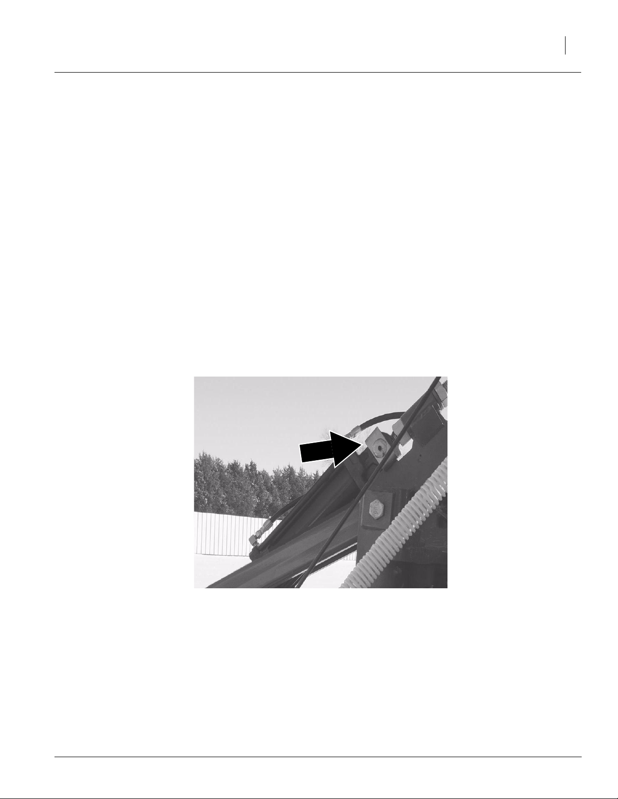
Install Hose Wrap and Cable Ties
Refer to Figure 16
1. If not cut already, cut spiral hose wrap in four
pieces. One piece will measure 4 foot, one piece
will measure 3 foot, and the remaining two pieces will measure 1 foot each.
NOTE: When wrapping hoses, only fertilizer
hose may be left out of hose wrap.
2. Using the 3 foot section, wrap all hydraulic lines
and electrical harness lines between left-hand
side toolbar/wing and center mainframe.
3. Start wrapping directly below fold cylinder rod
pin. Continue to wrap hoses up to the hose guide
on the toolbar pivot pin.
4. Using the 4 foot section, wrap all hydraulic lines
and electrical harness lines between right-hand
side toolbar/wing and center mainframe.
5. Start wrapping directly below fold cylinder rod
pin and continue to wrap beyond the hose guide
to control the hoses going on to the fan.
Refer to Figure 17
23421
Figure 16
Spiral Hose Wrap
6. If fertilizer hose is left out of hose wrap, route fertilizer hose along front of the hydraulic lines
crossing below tongue. All hoses must be routed
through hose clips forward of opener mounts to
avoid piniching when the wings flex up and
down.
12/12/2005
Figure 17
Fertilizer Hose
402-188M
Page 10

Base Update 2005 Kit
10
Refer to Figure 18
7. Remove 3/8-16 x 2 3/4 bolt from marker pivot
pin. Secure 13/16 hose clip to pivot pin using
removed bolt. Using hose clip, secue hydraulic
hose that goes to gauge wheel lift cylinder.
8. The two 1 foot sections will wrap hydraulic hoses going to gauge wheel lift cylinder. Start
wrapping hoses from hose clip out toward cylinder.
9. Repeat steps 4 and 5 on opposite side of
planter.
Great Plains Mfg., Inc.
23419
Figure 18
Hose Clip and Spiral Hose Wrap
Refer to Figure 19
10. Cover hoses entering pullbars with vinyl
sleeves - shiny side of sleeve against hoses.
Position hose sleeve with 10" of sleeve inside
pullbar and 14" outside . This covers hoses
passing through tongue and hitch area. Secure sleeve in place with velcro strips and use
a cable tie at each end to keep it from sliding.
11. Wrap hoses exiting pullbars with vinyl sleeves
- shiny side of sleeve against hoses. Sleeve
will extend 2-3" past support ring below pullbar pivot pin. Use cable tie at each end to keep
sleeve in place.
IMPORTANT! This is the end of instructions for the 2004 YP1625 Base Update
2005 Kit. If the planter is equipped with
fertilizer, please continue on to the next
Figure 19
Vinyl Sleeves
page for instructions on installing the
YP1625 Fertilizer Kit Update.
402-188M 12/12/2005
Page 11

Great Plains Mfg., Inc.
Assembly Instructions for 402-180A
Replace Nozzle Body Clamp
Refer to Figure 1
1. Detach nozzle body from nozzle body
clamp. Remove old clamp from supply tube.
Keep elbow fitting and orifice plate for reuse. Discard check valve and clamp.
NOTE: New nozzle body clamp has check valve
built into it. Separate check valve is no longer
necessary.
2. Attach new nozzle body clamp to fertilizer
supply tube. Reinstall orifice plate, elbow
fitting, and nozzle body.
3. Repeat steps for all clamps.
Installation Instructions
Figure 1
Nozzle Body Clamp
11
23422
Replace Fertilizer Hose Plastic Coupler
Refer to Figure 2
1. Uncouple fertilizer hose. Remove slip-on
coupler attaching fertilizer supply line to
opener attachment tube.
2. Replace coupler with new push-lok connector. Recouple hose.
3. Repeat steps for all hoses.
23423
Figure 2
Push-Lok Connector
12/12/2005
402-188M
Page 12

Base Update 2005 Kit
12
Replace Upper Sight Glass Fitting and Add
Decal
Refer to Figure 2
1. Remove hose from top, upper sight glass fitting by cutting hose at end of old hose barb.
NOTE: New fitting is longer and will make
up cut off length.
2. Unscrew elbow fitting and hose barb from top
of tank only. Replace sight glass fitting with
stainless steel elbow and hose barb fitting.
3. Reattach hose to new fitting.
Great Plains Mfg., Inc.
Cut Hose
Here
23424
Refer to Figure 5
4. Install level decal to front of tank as
shown. To simplify installation 4 inches
may be cut from decal. Cut 1 1/2" below
the 50 gallon mark. Make the second cut
5 1/2" below the 50 gallon mark. Then install decal above and below frame tube
so that 50 gallon mark is 1 1/2" upslope
from top of frame tube as shown.
Figure 2
Sight Glass Fittings
23426
23425
Figure 3
Fertilizer Tank
402-188M 12/12/2005
Page 13

Great Plains Mfg., Inc.
402-187A 2004 Yield-Pro® 1625 Planter Base Update 2005 Kit
Your kit includes:
Qty. Part No. Part Description
4 148-283H COULTER COMMAND CYLINDER PIN
1 401-226M MANUAL OP 12 & 16 ROW YP PLTR
2 401-258H YP HITCH PARK SUPPORT STAND
2 401-262H PARK STAND MOUNT
2 401-267H TRANSPORT SUPPORT HOOK WLDMT
2 402-158H 16R CASTER LOWER WLDMT
1 402-188M MANUAL 2004 YP BASE UPDATE 2005
32 403-105D IDLER PIVOT
32 403-115H IDLER BRACKET WELDMENT
1 403-164H MANIFOLD FRONT TOP WELDMENT 2
1 403-165H SEAL HOLDER WELDMENT
1 403-188H HOPPER WATER GUARD WELDMENT
1 403-189H SEED STRAINER GRATE WLDMNT
1 403-316D AIR DEFLECTOR
1 403-317D SEED CHAMBER DIVIDER LH
1 403-318D SEED CHAMBER DIVIDER RH
1 403-336D METER DRIVE ADAPTER
2 800-064C HOSE CLIP 13/16 ID
4 800-073C GREASE ZERK 1/4-28 X 90-DEG
12 800-082C CABLE TIE .31 X 21.5 6DIA 120LB
64 800-085C SNAP RING EXT 1 HEAVY
4 802-318C HHCS 3/8-16 X 5 GR5
4 802-800C HWH #12-14 X 3/4
4 803-014C NUT HEX 3/18-16 PLT
4 803-020C NUT HEX 1/2-13 PLT
4 804-015C WASHER LOCK SPRING 1/2 PLT
2 804-028C WASHER FLAT 1 USS PLT
1 805-024C PIN ROLL 3/16 X 1 1/2 PLT
4 805-212C PIN WIRE SNAP LOCK 3/8 X 2 1/2
2 806-060C U-BOLT 1/2-13 X 6 1/32 X 7 1/4
2 807-260C SPRING COMP 1.460D .148W X 4.0LG
1 816-478C AUX METER TOP SEAL
2 816-479C SEAL TOP CORNER
4 816-480C HOSE WRAP 3.0-4.5 X 24 LG VELCR
64 817-083C PRESS WHEEL ARM PIVOT BUSHING
64 817-406C IDLER 1 PC 2.38 X 1.0 X 1.062
1 817-624C FAN INLET RAIN SHIELD
1 890-179C SILICON 35YR CLEAR 10 OZ
9 990-228R SPIRAL HOSE WRAP 1 ID PLASTIC
Installation Instructions
13
402-180A Yield-Pro® 1625 Planter Fertilizer Update Kit 2005
Your kit includes:
Qty. Part No. Part Description
32 829-089C NOZZLE BODY 3/4 WET BOOM CL
2 830-380C EL 3/4 MNPT X 3/4 FNPT SS
2 830-381C AD 3/4 MNPT X 3/4 HB SS
32 830-383C CP 1/4 PUSH LOK POLY
2 838-823C DECAL YP FERTILIZER LEVEL
12/12/2005
402-188M
 Loading...