

Great Plains VT7300 User Manual
Operators/Parts Manual
Verti-Till 5300, 7225, 7300 & 9225
Finishing Attachments
Manufacturing, Inc.
Read the operator’s manual entirely. When you see this symbol, the
!
subsequent instructions and warnings are serious - follow without exception.
Your life and the lives of others depend on it!
©Copyright 2005 Printed 4/8/2010 596-156M

General Information Table of Contents ► Great Plains Mfg., Inc.
General Information
Great Plains Manufacturing, Inc. provides this
publication “as is” without warranty of any kind,
either expressed or implied. While every
precaution has been taken in the preparation of
this manual, Great Plains Manufacturing, Inc.
assumes no responsibility for errors or omissions.
Neither is any liability assumed for damages
resulting from the use of the information contained
herein. Great Plains Manufacturing, Inc. reserves
the right to revise and improve its products as it
sees fit. This publication describes the state of this
product at the time of its publication, and may not
reflect the product in the future.
Printed in the United States of America.
For your convenience, record your Serial Number,
Model Number and the Date Purchased in the
spaces provided below. Have this information
available when calling your Great Plains
Authorized Dealer.
Owner’s Information
Name:_______________________________
Address _____________________________
City______________State ____ Zip _______
Phone_______________________
Name of Dealership ____________________
Dealer’s Name ________________________
Address _____________________________
City______________State ____ Zip _______
Phone_______________________
Verti-Till VT5300-VT9225 Finishing Attachments 596-156M 6/30/2008
Serial Number ___________________
Model Number ___________________
Date Purchased __________________

Great Plains Mfg., Inc. Table of Contents
Table of Contents
Using This Manual .............................................2
Introduction ........................................................2
Section 1 Safety Rules ........................................3
General Operation & Repair .........................3
Transporting .................................................3
Safety Decals ................................................3
Section 2 Assembly & Set-Up ............................4
Ridge Splitter Assembly ...............................4
Rolling Harrow Assembly ............................5
Seedbed Conditioner to Verti-Till
Attachment ..............................................6
Section 3 Operating Instructions ......................8
Prior to Going to the Field ............................8
General Operating Instructions and
In-Field Adjustments ...............................8
Section 4 Maintenance & Lubrication .............9
General Maintenance ....................................9
Lubrication ...................................................9
Section 5 Parts & Hydraulics.............................10
Ridge Splitter ................................................10
Rolling Harrow .............................................12
Seedbed Conditioner Frame .........................14
Seedbed Conditioner Baskets
(S/N 1079MM-) ............................................16
Seedbed Conditioner Baskets
(S/N 1080MM-) ............................................18
Seedbed Conditioner Hydraulics ..................20
Seedbed Conditioner Transport ....................22
Seedbed Conditioner Decals ........................24
Section 6 Machine Layouts ............................... 26
VT5300 Ridge Splitter ................................. 26
VT7300 Ridge Splitter ................................. 27
VT5300 & VT7225 Rolling Harrow ............28
VT7300 & VT9225 Rolling Harrow ............29
VT5300 Ridge Splitter & Rolling Harrow ... 30
VT7300 Ridge Splitter & Rolling Harrow ... 31
VT5300 & VT7225 Seedbed Conditioner ... 32
VT7300 & VT9225 Seedbed Conditioner ... 33
VT5300 Ridge Splitter & Seedbed
Conditioner .............................................. 34
VT7300 Ridge Splitter & Seedbed
Conditioner .............................................. 35
Appendix .............................................................36
Torque Values for Common Bolt Sizes ....... 36
Tire Inflation Chart ...................................... 36
6/30/2008 Verti-Till VT5300-VT9225 Finishing Attachments 596-156M
1

Using This Manual Table of Contents ► Great Plains Mfg., Inc.
Using This Manual
For your safety and to help in developing a better
understanding of your equipment we highly
recommend that you read the operator sections of
this manual. Reading these sections not only
provides valuable training but also familiarizes you
Introduction
This manual has been prepared to instruct you in
the safe and efficient operation of your Finishing
Attachment. Read and follow all instructions and
safety precautions carefully.
The parts on your Finishing Attachment have
been specially designed and should only be
replaced with genuine Great Plains parts.
Therefore, should your Finishing Attachment
require replacement parts go to your Great
Plains Dealer.
The right hand and left hand as used throughout
this manual is determined by facing in the
direction the machine will travel when in use
unless otherwise stated.
!
!
The SAFETY ALERT SYMBOL indicates that
there is a potential hazard to personal safety
involved and extra safety precautions must be
taken. When you see this symbol, be alert and
carefully read the message that follows it. In
addition to design and configuration of equipment;
hazard control and accident prevention are
dependent upon the awareness, concern,
prudence and proper training of personnel
involved in the operation, transport, maintenance
and storage of equipment.
with helpful information and its location. The parts
sections are for reference only and don’t require
cover to cover reading. After reviewing your
manual store it in a dry, easily accessible location
for future reference.
Watch for the following safety notations throughout your Operators Manual:
!
! DANGER!
Indicates an imminently hazardous situation which, if
not avoided, will result in death or serious injury. This
signal word is limited to the most extreme situations.
!
! WARNING!
Indicates a potentially hazardous situation which, if
not avoided, could result in death or serious i njury.
!
! CAUTION!
Indicates a potentially hazardous situation which,
if not avoided, may result in minor or moderate
injury. It may also be used to alert against unsafe
practices.
Note: Indicates a special point of information
which requires your attention.
Verti-Till VT5300-VT9225 Finishing Attachments 596-156M 6/30/2008
2

Great Plains Mfg., Inc. Table of Contents ► Section 1: Safety Rules
Safety Rules
Most accidents are the result of negligence and
carelessness, usually caused by failure of the
operator to follow simple but necessary safety
precautions. The following safety precautions are
suggested to help prevent such accidents. The
safe operation of any machinery is a big concern
to consumers and manufacturers. Your Finishing
Attachment has been designed with many built-in
safety features. However, no one should operate
this product before carefully reading this
Operators Manual.
General Operation & Repair
1. NEVER permit anyone near machinery while in
operation.
2. Excessive speed can cause machine damage.
3. NEVER allow anyone to be near the machine
when folding wings.
4. Reduce speed of the tractor when transporting
over uneven or rough terrain. Avoid all chuck
holes and washboard areas in roads.
5. Reduce speed of the tractor when transporting
over hills or steep slopes.
6. DO NOT lubricate, adjust or repair the machine
while it is in operation.
7. Use "Slow Moving Vehicle" emblem for warning
vehicles approaching from the rear.
8. DO NOT permit smoking, sparks, or an open
flame where combustible lubricants or liquids are
being used.
!
! CAUTION! Escaping fluid under
9.
pressure can have sufficient force to penetrate the
skin. Check all hydraulic lines and hoses
BEFORE applying pressure. Fluid escaping from
a very small hole can be almost invisible. Use
paper or cardboard, NOT BODY PARTS, to
check for suspected leaks. If injured, seek medical
assistance from a doctor that is familiar with this
type of injury. Foreign fluids in the tissue must be
surgically removed within a few hours or
gangrene will result.
Transporting
1. Use good judgement when transporting tractor
and implements on the highway. Always maintain
complete control of the machine.
2. Use warning flags or approved warning lights at
night and during other periods of poor visibility.
Do your best to prevent highway accidents.
3. When in transport, use accessory lights and
devices for adequate warning to operators of other
vehicles and use safety hitch chain. Comply with
all Federal, State and Local laws when traveling
on public roads.
4. Reduce speed of the tractor when transporting
over hills or steep slopes.
5. Reduce speed of the tractor when transporting
over uneven or rough terrain. Avoid all chuck
holes and washboard areas in roads.
Safety Decals
1. Your Finishing Attachment come equipped
with all safety decals in place. They were designed
to help you safely operate your Finishing
Attachment. Read and follow their directions.
2. Keep safety decals clean and legible.
3. Replace all damaged or missing safety decal s. To
order new safety decals go to your Great Plains
Dealer and refer to the parts section for safety
decal package part number.
4. Replace these decals whenever they become worn
or unreadable. To instal new safety decals:
a) Clean the area the decal is to be placed.
b) Peel backing from the decal. Press firmly on
to surface being careful not to cause air
bubbles under the decal.
6/30/2008 Verti-Till VT5300-VT9225 Finishing Attachments 596-156M
3
Section 2: Assembly & Set-Up Table of Contents ► Great Plains Mfg., Inc.
Assembly & Set-Up
This section covers the proper assembly of the finishing attachment. The reference numbers
on the figures give you an indication of the order of assembly. For a complete breakdown of any
parts not shown in this assembly section, refer to Section 5, Parts & Hydraulics, starting on page 10.
Refer to Section 6, page 26-35, for proper location of attachments. Go to the Appendix for proper
bolt torque values.
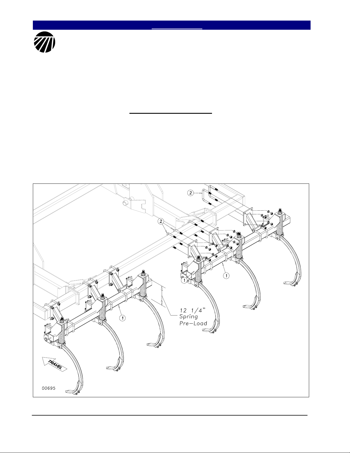
Ridge Splitter Assembly
Move the machine to a safe, clean
working area before proceeding. The ridge
splitter assembly will come completely
assembled from the factory. Start by locating
the ridge splitter assembly. For ease of
assembly you should use an over head hoist or
fork lift to mount assemblies. Bolt the ridge
splitter assembly (1) to the rear bar of the Vertitill using 3/4 x 6 x 5 5/8 u-bolts (2) and secure
with lockwashers and hex nuts as shown in
Figure 1. Verify placement dimensions for
model of machine in the Machine Layout
section and tighten bolts. Spring shank preload
should be 12¼ inches as measured at spring.
Figure 1
Verti-Till VT5300-VT9225 Finishing Attachments 596-156M 6/30/2008
4
Great Plains Mfg., Inc. Table of Contents ► Section 2: Assembly & Set-Up
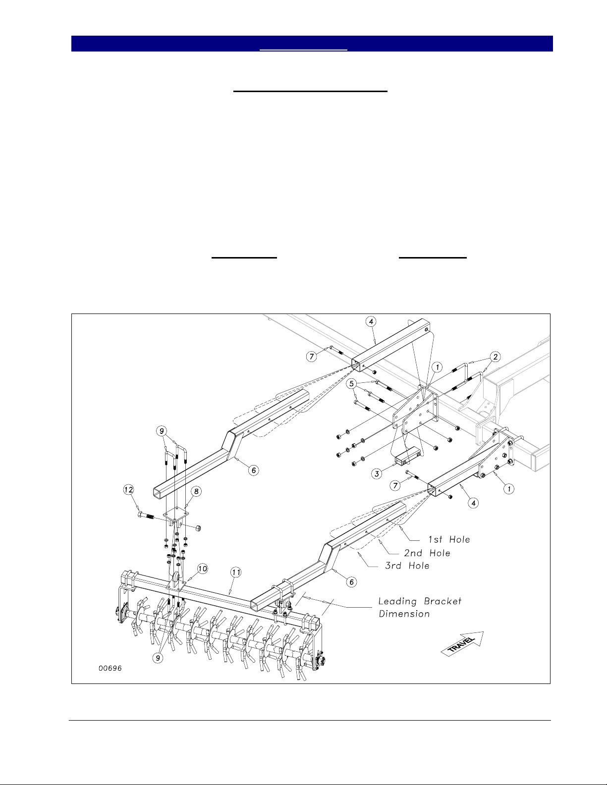
Rolling Harrow Assembly
Move the machine to a safe, clean
working area before proceeding. Start by Ubolting the VT rolling harrow brackets (1) to
the rear bar of the Verti-till as shown in Figure
2. Use 3/4 x 6 x 5 5/8 u-bolts (2) with lock
washers and hex nuts. Refer to Section 6
Machine Layouts for placement dimensions.
Bolt the VT rolling harrow arm rest (3) and
rolling harrow sleeve (4) to the harrow bracket
(1) with three 3/4 x 5 1/2 hex bolts (5) using
lock nuts. Draw up snug but do not torque,
arm must move freely. Slide the VT rolling
harrow arms (6) into the harrow sleeves (4) and
bolt through the proper hole with 5/8 x 4 1/2
hex bolts (7) using 5/8 lock nuts.
the harrow arms (6) using 5/8 x 3 x 4 1/2 ubolts (9) and lock washers and hex nuts. U-bolt
the ball-joint brackets (10) to the rolling harrow
module (11) with same hardware as above
placing the leading bracket at the dimension on
the layout. Tighten the leading ball joint
bracket down and leave the rear bracket loose.
Attach the harrow module (11) to the harrow
arms (6) with the 1 x 4 hex bolts (12) using a
nylon lock nut. Do not torque nylon lock nut.
After verifying the placement dimensions on
the layout drawing, finish tightening the
remaining u-bolts on the brackets.
U-bolt the rolling harrow brackets (8) to
Figure 2
6/30/2008 Verti-Till VT5300-VT9225 Finishing Attachments 596-156M
5

Section 2: Assembly & Set-Up Table of Contents ► Great Plains Mfg., Inc.
Seedbed Conditioner to Verti-Till Attachment
The Seedbed Conditioner will come
completely assembled with the pintle hook,
cable and brackets banded to conditioner. Start
by Carefully taking banding loose and bolting
the 5-ton pintle hook (1) to the semi-mount
pintle bracket (2) with four 1/2 x 2 Gr.8
mounting bolts (3) using 1/2” flat washers,
lock washers and hex nuts as shown in Figure
3. U-bolt this assembly to the rear bar of the
Verti-Till using two 3/4 x 6 x 5 5/8 u-bolts (4)
with lock washers and hex nuts.
U-bolt the semi-mount cable brackets
(5) to the Verti-Till rear frame frame with 5/8
x 6 x 5 1/4 u-bolts (6). Secure with 5/8 lock
washers and hex nuts (see Section 6 Machine
Layouts, for proper placement dimensions).
If the Vert-Till gets a Ridge Splitter
attachment, install it as shown in previous
assembly instructions.
Hitch the seedbed conditioner to the
Verti-Till at the Pintle hook and drawbar ring.
Secure Pintle hook latch with wire lock pin.
Attach the appropriate length cables (7) along
with the cable spacers (8) using the 5/8 bent
pins with hairpin cotters (9) on the Verti-Till
end.
Figure 3
Verti-Till VT5300-VT9225 Finishing Attachments 596-156M 6/30/2008
6

Great Plains Mfg., Inc. Table of Contents ► Section 2: Assembly & Set-Up
This page intentionally left blank.
6/30/2008 Verti-Till VT5300-VT9225 Finishing Attachments 596-156M
7
Section 3: Operating Instructions Table of Contents ► Great Plains Mfg., Inc.
Operating Instructions
Prior to Going to the Field
1. Both dealer and customer read and
thoroughly understand all safety
recommendations. (These are found in the
Safety Section of this operator manual.)
2. Make sure your tractor horsepower matches
the implement you are pulling. This is
important so the implement can do the best
possible job.
3. Clean all hydraulic couplings and connect to
tractor or host implement. Each hydraulic
coupling has a colored handle on it and is
marked with a cylinder, either extending or
retracting.
4. After the seedbed conditioner is attached,
raise and lower the seedbed conditioner
several times to purge air from the hydraulic
system. Again check for hydraulic leaks and
tighten or replace if necessary.
5. Check the tire pressure for proper inflation
and check the tightness of the lug bolts. Tire
pressure information can be found in the
Appendix of this manual.
6. Check for any bolts that may need tightened
or retightened. Grease all the hinge points.
The hubs come pre-greased and will not need
more grease at this time.
7. Prior to transporting, fully raise the seedbed
conditioner. Install the transport locks. Always
use the transport locks when moving from
field to field in case of a hydraulic hose failure.
You are now ready to go to the field.
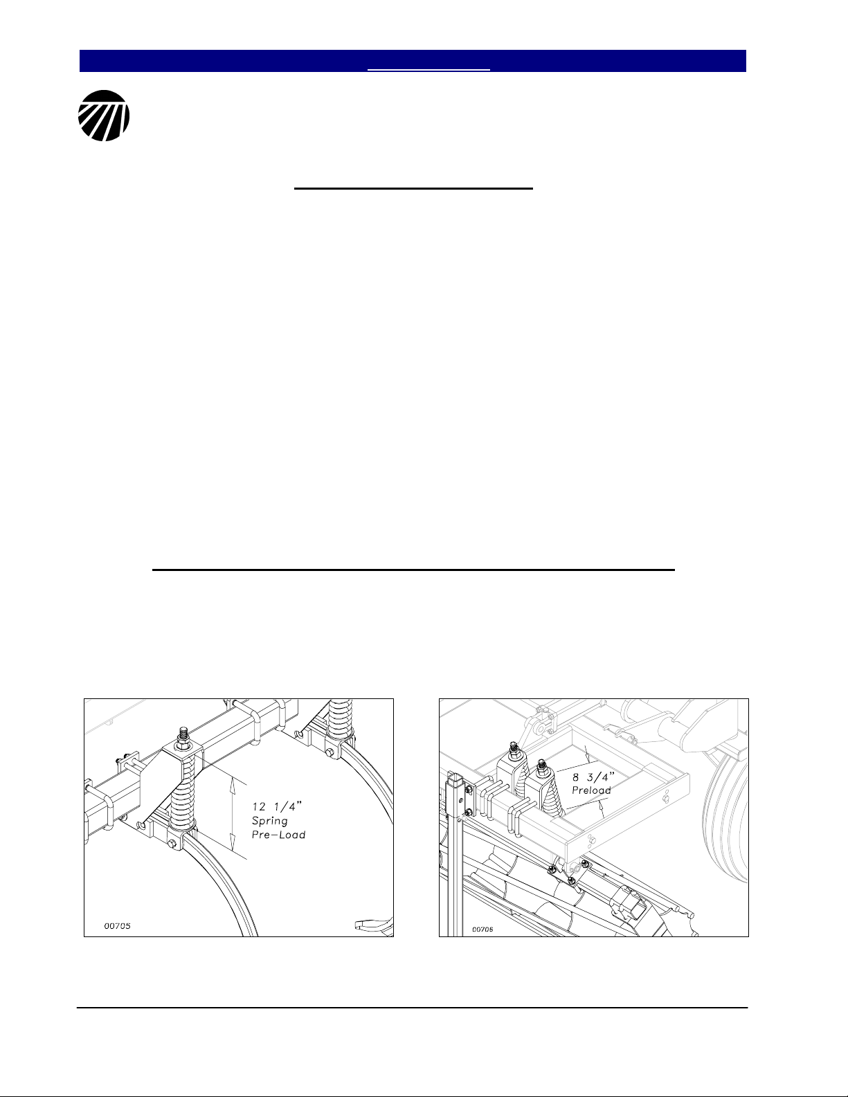
General Operating Instructions and In-Field Adjustments
1. Extend the seedbed conditioner lift cylinders
and remove the transport locks.
2. Set the pre-load on the ridge splitter shanks to
12 1/4” spring length.
3. Check the pre-load on the seedbed
conditioner baskets to 8 3/4” spring length.
4. The seedbed conditioner should be raised
with the host implement when turning.
Verti-Till VT5300-VT9225 Finishing Attachments 596-156M 6/30/2008
8
Great Plains Mfg., Inc. Table of Contents ► Section 4: Maintenamce & Lubrication
Maintenance & Lubrication
1. Always use the transport lock when
working or doing maintenance on the
seedbed conditioner. Read and
understand all safety decals on your
equipment.
2. During the first season of operation, and
periodically after that, check your bolts for
tightness.
3. Check wheel bearings occasionally for
excessive endplay.
4. Replace or rotate worn parts as needed—
bolts, clevis pins, bearings, chisel points
etc...
5. Check and tighten or replace any
hydraulic leaks. Check hoses for any
leaks. It is important that there are no
leaks on the equipment.
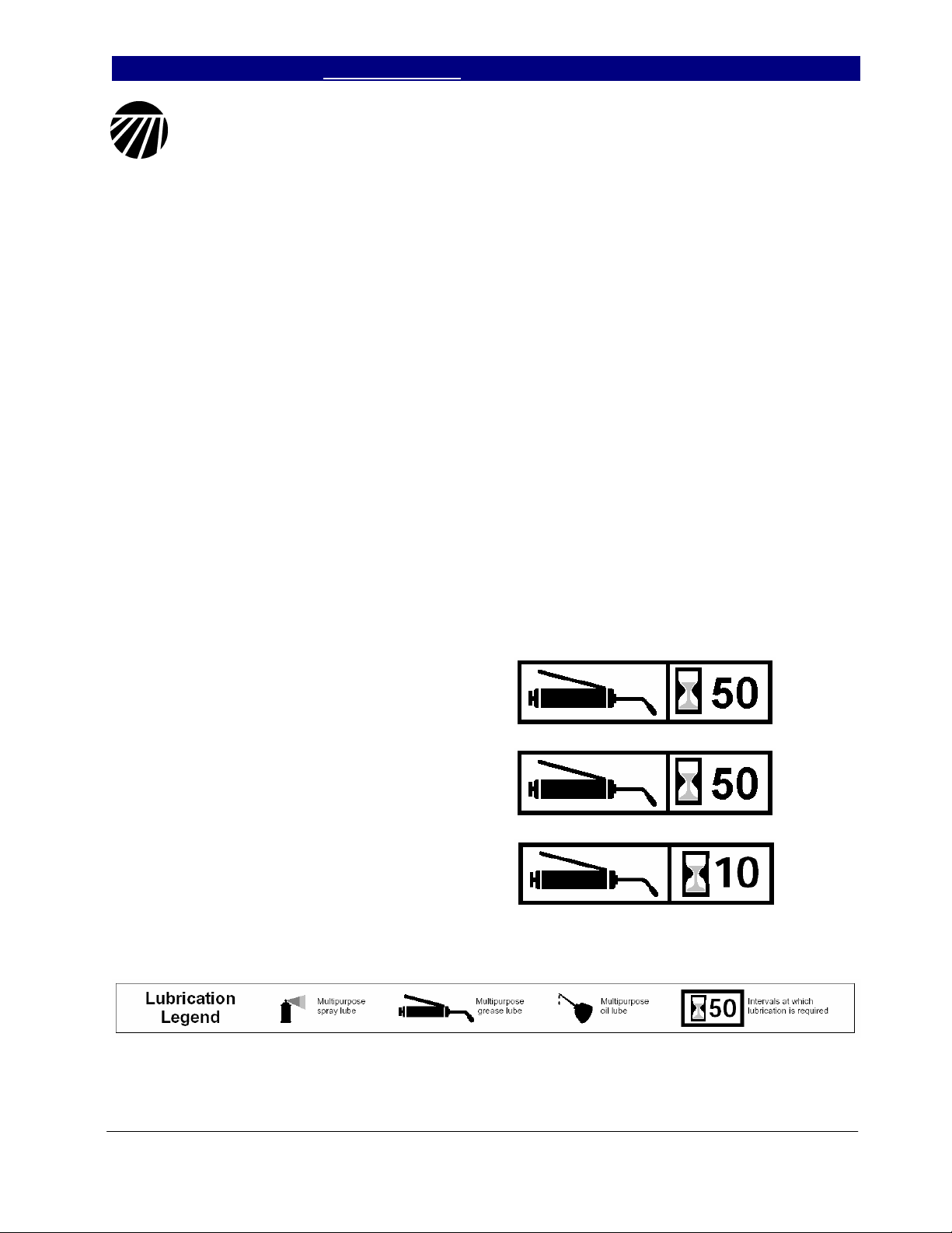
6. Grease reel bearings and wheel
bearings sparingly. Over greasing may
cause damage to seals and reduce the
life of the bearing. Grease hinge points
periodically.
Reel Bearings
Grease every 50 hours (sparingly).
7. If machine is stored outdoors over the winter
months it is a good idea to retract the
cylinders to protect the cylinder rods. This
will extend the life of the cylinder seals and
reduce internal and external leaks.
By following and maintaining a routine service and
lubrication program, your tillage attachment will
give you many years of service.
For more information on operating, adjusting
or maintaining your Great Plains Verti-Till
Attachment contact your local Great Plains
dealer or call
Great Plains Mfg. at (800) 255-9215
Wheel Bearings
Grease every 50 hours (sparingly) and
check for endplay.
Caster Wheels Pivots
Grease every 10 hours.
6/30/2008 Verti-Till VT5300-VT9225 Finishing Attachments 596-156M
9
Section 5: Parts & Hydraulics Table of Contents ► Great Plains Mfg., Inc.
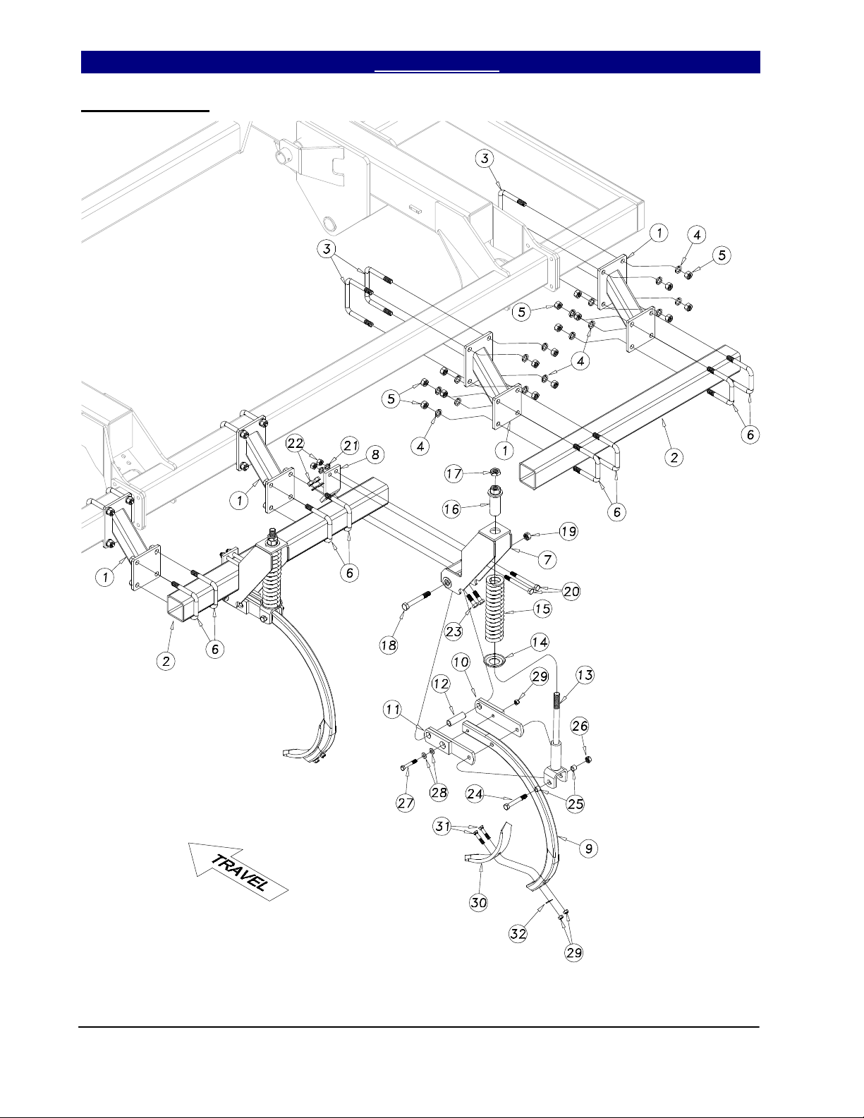
Ridge Splitter
01137
Verti-Till VT5300-VT9225 Finishing Attachments 596-156M 6/30/2008
10
 Loading...