

Page 1

Operator Manual
V300 and V300F
Verti-Drill
s/n: A1043L+
Manufacturing, Inc.
www.greatplainsmfg.com
Read the operator’s manual entirely. When you see this symbol, the subsequent
instructions and warnings are serious - follow without exception. Your life and
!
the lives of others depend on it!
22574
Cover illustration may show optional equipment not supplied with standard unit.
© Copyright 2007 Printed 11/15/2007 148-057M-A
Page 2

-2 V300 & V300F Great Plains Manufacturing, Inc.
Blank page for correct duplexing.
148-057M-A 11/15/2007
Page 3

Great Plains Manufacturing, Inc.
Table of Contents
Important Safety Information ............................................. 1
Safety Decals and Reflectors ................................................ 6
Introduction ....................................................................... 12
Description of Unit ............................................................... 12
Document Family ................................................................ 12
Models Covered .................................................................. 12
Intended Usage ................................................................... 12
Using This Manual............................................................... 12
Definitions ....................................................................... 12
Owner Assistance ............................................................... 13
Setup .................................................................................. 14
Pre-Start Checklist .............................................................. 14
Negative Tongue Weight..................................................... 14
Hitching Tractor to Implement ............................................. 15
Electrical Connections......................................................... 16
Hydraulic Connections ........................................................ 17
Hydraulic Charge and Bleed ............................................... 17
Monitor Installation .............................................................. 18
Monitor Setup ...................................................................... 18
Install Other Options............................................................ 18
Leveling Drill........................................................................ 19
Leveling Order Summary ................................................ 19
Check Tires, Blades & Mounts........................................ 20
Disable Seeding & Weight Drill ....................................... 20
Disable Seeding............................................................... 20
Adjust at Half Material Weight.......................................... 20
Initial Seeding Depth....................................................... 21
Initial Lift Cylinder Spacers ............................................. 21
Initial Down-Pressure...................................................... 22
Set or Calibrate Bypass ................................................... 22
Set Bypass for PC Closed ............................................... 22
Set Bypass for LS Closed/PFC........................................ 22
Set Down Pressure .......................................................... 22
Initial Hitch Height ........................................................... 23
Lowering for Leveling....................................................... 23
Initial Hitch Height ............................................................ 23
Lower Drill, Pull Forward and Check............................... 23
Hydraulic Hitch Adjustment............................................. 24
Lift Spacer Adjustments .................................................. 24
Marker Setup....................................................................... 25
Dual Marker Setup .......................................................... 25
Dual Marker Extension..................................................... 25
Dual Marker Disk Setup ................................................... 26
Dual Marker Speed .......................................................... 26
Pre-Emergence Marker Setup ........................................ 27
Tramline Marker Disk Setup ............................................ 27
Packer Setup....................................................................... 28
Harrow Setup .......................................................................29
Harrow Height Setup........................................................29
Harrow Tine Setup ...........................................................29
Operations ..........................................................................30
Pre-Start Checklist ...............................................................30
Transport..............................................................................30
Lift Cylinder Locks............................................................31
Down Pressure Cylinder Lock..........................................31
Pivot Lock ........................................................................32
Walkboards ......................................................................32
Ready for Transport .........................................................32
Set Material Rate(s) .............................................................33
Material Loading...................................................................33
Main Seed Box & Fertilizer Loading.................................33
Small Seed Box Loading..................................................34
Lift/Lower Operations ...........................................................35
Lowering the Drill .............................................................35
Raising the Drill................................................................35
Lift Cylinders During Operations ......................................35
Hydraulic Down Pressure ................................................36
Priority Flow Hydraulic Systems ......................................38
Final Field Preparation .........................................................39
Field Operation.....................................................................39
Marker Operation .................................................................40
Dual Marker Operation.....................................................40
Pre-Emergence Marker Operation...................................40
Harrow Operation.................................................................41
Parking .................................................................................42
Storage.................................................................................42
Monitor Operation ..............................................................43
Monitor Introduction..............................................................43
Console Overview ................................................................44
Channel Indicator Chevron ..............................................45
Channel Select.................................................................45
Normal Display Mode.......................................................45
Initial Console Setup ............................................................45
Program Modes ...............................................................46
Units .....................................................................................47
Changing Units of Measure .............................................47
Forward Speed Function......................................................48
Forward Speed Alarm ......................................................48
Disable Forward Speed Alarm.......................................... 48
Speed Sensor Factor .......................................................49
Autocal.............................................................................. 49
Manual S.S.F. Entry .........................................................50
Area Function.......................................................................51
Display Current Area Totals.............................................51
© Copyright 2005, 2006, 2007. All rights Reserved.
Great Plains Manufacturing, Inc. provides this publication “as is”without warranty of any kind, either expressed or implied. While every precaution has been taken in the preparation
of this manual, Great Plains Manufacturing, Inc. assumes no responsibility for errors or omissions. Neither is any liability assumed for damages resulting from the use of the information contained herein. Great Plains Manufacturing, Inc. reserves the right to revise and improve its products as it sees fit. This publication describes the state of this product at
the time of its publication, and may not reflect the product in the future.
The following are trademarks of Great Plains Mfg., Inc.: Application Systems, Ausherman, Land Pride, Great Plains
All other brands and product names are trademarks or registered trademarks of their respective holders.
11/15/2007 148-057M-A
Great Plains Manufacturing, Incorporated Trademarks
Printed in the United States of America.
Page 4

V300 & V300F Great Plains Manufacturing, Inc.
Display Grand Total .........................................................51
Reset Totals.....................................................................51
Set Implement Width........................................................52
Tramlining Function..............................................................53
Tramline Sequence/Bout Selection..................................54
Select The Sequence....................................................... 54
Select the Tramline Bout.................................................. 54
Normal Tramline Operations............................................55
Hold the Bout Number .....................................................55
Manually advance the bout number.................................55
Turn Tramlining Off/On ....................................................56
12 Meter Symmetric Tramlining Sequence......................57
15 Meter Symmetric Tramlining Sequence......................58
18 Meter Symmetric Tramlining Sequence......................59
12 Meter Asymmetric Right Tramlining Sequence...........60
18 Meter Asymmetric Right Tramlining Sequence...........61
12 Meter Asymmetric Left Tramlining Sequence .............62
20 Meter 20 Bout Tramlining Sequence ..........................63
Fertilizer Shaft Function .......................................................64
Display Fertilizer Shaft Speed..........................................64
Fertilizer Shaft Alarm .......................................................64
Fertilizer Shaft Setup .......................................................64
Disable Fertilizer Shaft Alarm ..........................................65
Fertilizer Alarm Speed Threshold ....................................65
Fertilizer Alarm Delay Time..............................................66
Seed Shaft Function.............................................................66
Display Seed Shaft Speed ...............................................66
Seed Shaft Alarm.............................................................66
Seed Shaft Setup.............................................................67
Disable Seed Shaft Alarm................................................67
Seed Alarm Speed (Shaft Rate) ......................................68
Seed Alarm Delay Time ...................................................68
Hopper Level Function .........................................................69
Enable / Disable Hopper Level Alarm ..............................69
Adjustments .......................................................................70
Planting Depth......................................................................70
Coulter Adjustments.............................................................71
Coulter Factory Settings ..................................................71
Gang Coulter Depth.........................................................71
Individual Coulter Depth...................................................71
Coulter Height .................................................................. 71
Coulter Down-Force......................................................... 72
Opener Down-Pressure .......................................................73
Frame Weights.................................................................73
Material Rate Adjustments ...................................................74
Calibration Crank Revolutions .........................................74
Setting Main Seed Box Rate............................................75
Setting Drive Type ........................................................... 75
Setting Meter Rate ........................................................... 76
Position Seed Cup Doors.................................................77
Disabling Main Seed Box Drive .......................................77
Calibrating Main Box Seed Rate......................................78
Small Seeds Attachment Rate .........................................80
Small Seeds Rate Handle................................................ 80
Disabling Small Seeds ..................................................... 80
Small Seeds Rate Calibration .......................................... 81
Setting Fertilizer Rate ......................................................83
Fertilizer Density Correction............................................. 84
Example Fertilizer Density Correction ..............................84
Setting Fertilizer Drive Range........................................... 84
Setting Fertilizer Transmission .........................................85
Setting the Fertilizer Adjuster............................................85
Disabling Fertilizer Box Drive...........................................86
To re-enable fertilizer drive: ..............................................86
Fertilizer Rate Calibration .................................................86
Row Unit Adjustments..........................................................89
Opener Height .................................................................90
Row Unit Down Pressure (Spring)...................................90
Disk Blade Adjustments...................................................91
Adjusting Disc Contact......................................................91
Disk Scraper Adjustments ...............................................91
Seed Firmer Adjustments ................................................92
Seed-Lok™ Seed Firmer Lock-Up....................................92
Opener Depth (Press Wheel Height) ...............................93
Troubleshooting.................................................................94
Maintenance and Lubrication ...........................................96
Maintenance.........................................................................96
Bleeding Hydraulic Systems ............................................96
Check/Clean In-Line Filter ................................................97
Bleeding Tongue Cylinder ................................................97
Bleeding Transport Lift Cylinders......................................98
Bleeding Down-Pressure Cylinder.................................... 99
Bleeding Tramline Lift Cylinders .......................................99
Marker Maintenance ......................................................100
Bleeding Marker Hydraulics............................................ 100
Leaf Spring Adjustment .................................................101
Chain Maintenance........................................................101
Box Cleanout .................................................................102
Main Box Cleanout .........................................................102
Small Seeds Box Cleanout .............................................102
Fertilizer Box Cleanout ...................................................103
Lubrication..........................................................................104
Options..............................................................................111
Dual Markers......................................................................111
Packer ................................................................................111
Seed Tube Plugs................................................................112
Third Tramline Clutch.........................................................112
Small Seeds .......................................................................112
Seed-Lok Seed Firmer .......................................................113
Harrow................................................................................113
Tramline Markers ...............................................................113
Appendix...........................................................................114
Specifications and Capacities ............................................114
Tire Inflation Chart..............................................................114
Torque Values....................................................................115
Chain Routing ....................................................................116
Contact, Right and Main Seed Chains...........................116
Fertilizer and Small Seed Chains ..................................117
Hydraulic Diagrams............................................................118
Lift and Down-Pressure Hydraulics ...............................118
Dual Marker Hydraulics .................................................119
ASAE Lighting Circuit.........................................................119
Coulter Stations..................................................................120
Warranty.............................................................................121
Index..................................................................................123
148-057M-A 11/15/2007
Page 5

Great Plains Manufacturing, Inc. 1
Important Safety Information
Look for Safety Symbol
The SAFETY ALERT SYMBOL indicates there is a
potential hazard to personal safety involved and extra
safety precaution must be taken. When you see this
symbol, be alert and carefully read the message that follows it. In addition to design and configuration of equipment, hazard control and accident prevention are
dependent upon the awareness, concern, prudence and
proper training of personnel involved in the operation,
transport, maintenance and storage of equipment.
Be Aware of Signal Words
Signal words designate a degree or level of hazard seriousness.
DANGER indicates an imminently hazardous situation
which, if not avoided, will result in death or serious injury.
This signal word is limited to the most extreme situations,
typically for machine components that, for functional purposes, cannot be guarded.
WARNING indicates a potentially hazardous situation
which, if not avoided, could result in death or serious
injury, and includes hazards that are exposed when
guards are removed. It may also be used to alert against
unsafe practices.
CAUTION indicates a potentially hazardous situation
which, if not avoided, may result in minor or moderate
injury. It may also be used to alert against unsafe practices.
!
!
!
!
DANGER
WARNING
CAUTION
Be Familiar with Safety Decals
▲ Read and understand “Safety Decals and Reflectors”on
page 6, thoroughly.
▲ Read all instructions noted on the decals.
Negative Tongue Weight
This drill can have positive and negative tongue weight,
and it can change during planting. This poses a serious
hazard during unhitching and it can work the hitch pin
loose during transport. To avoid serious injury or death
due to a rising hitch or road accident:
▲ Always use the clevis hitch provided.
▲ Always hitch before connecting hydraulics.
▲ Always lower the openers and install the jackstand before
unhitching.
11/15/2007 148-057M-A
Page 6
2 V300 & V300F Great Plains Manufacturing, Inc.
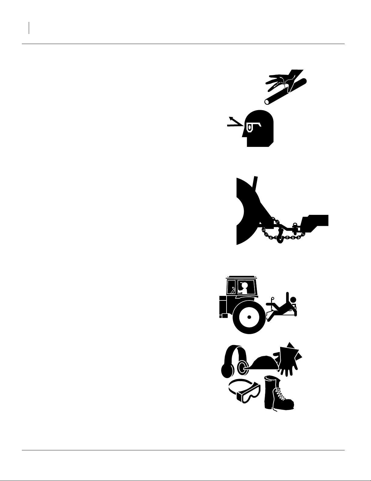
Avoid High Pressure Fluids
Escaping fluid under pressure can penetrate the skin,
causing serious injury.
▲ Avoid the hazard by relieving pressure before disconnecting
hydraulic lines.
▲ Use a piece of paper or cardboard, NOT BODY PARTS, to
check for suspected leaks.
▲ Wear protective gloves and safety glasses or goggles when
working with hydraulic systems.
▲ If an accident occurs, seek immediate medical attention
from a physician familiar with this type of injury.
Use A Safety Chain
▲ Use a safety chain to help control drawn machinery should
it separate from tractor drawbar.
▲ Use a chain with a strength rating equal to or greater than
the gross weight of towed machinery.
▲ Attach chain to tractor drawbar support or other specified
anchor location. Allow only enough slack in chain to permit
turning.
▲ Replace chain if any links or end fittings are broken,
stretched or damaged.
▲ Do not use safety chain for towing.
Keep Riders Off Machinery
▲ Riders obstruct the operator’s view. Riders could be struck
by foreign objects or thrown from the machine.
▲ Never allow children to operate equipment.
▲ Keep all bystanders away from machine during operation.
Wear Protective Equipment
▲ Wear protective clothing and equipment.
▲ Wear clothing and equipment appropriate for the job. Avoid
loose-fitting clothing.
▲ Because prolonged exposure to loud noise can cause hear-
ing impairment or hearing loss, wear suitable hearing protection such as earmuffs or earplugs.
▲ Because operating equipment safely requires your full
attention, avoid wearing entertainment headphones while
operating machinery.
148-057M-A 11/15/2007
Page 7
Great Plains Manufacturing, Inc. 3
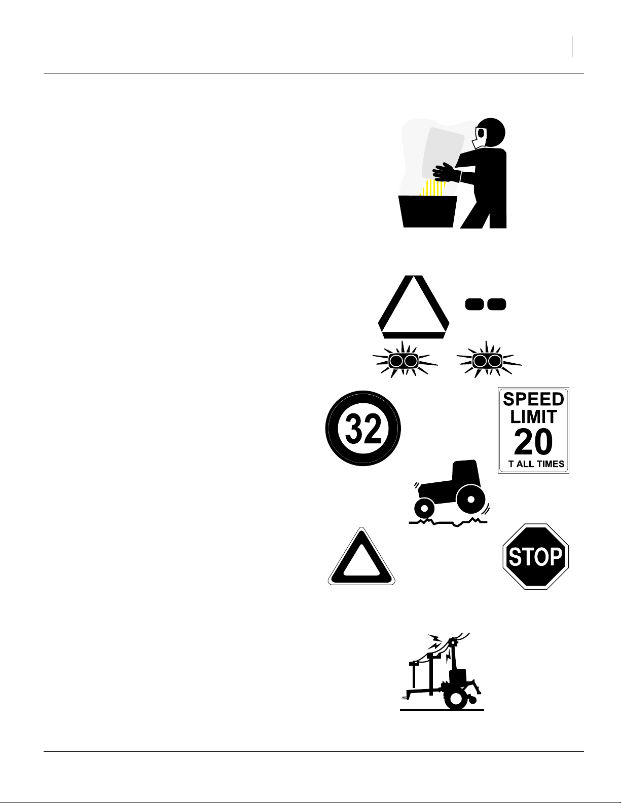
Handle Chemicals Properly
Agricultural chemicals can be dangerous. Improper use
can seriously injure persons, animals, plants, soil and
property.
▲ Read and follow chemical manufacturer’s instructions.
▲ Wear protective clothing.
▲ Handle all chemicals with care.
▲ Avoid inhaling smoke from any type of chemical fire.
▲ Store or dispose of unused chemicals as specified by chemi-
cal manufacturer.
Use Safety Lights and Devices
▲ Slow-moving tractors and towed implements can create a
hazard when driven on public roads. They are difficult to
see, especially at night.
▲ Use flashing warning lights and turn signals whenever driv-
ing on public roads.
▲ Use lights and devices provided with implement.
Transport Machinery Safely
Maximum transport speed for implement is 32 kph (20
mph). Some rough terrains require a slower speed. Sudden braking can cause a towed load to swerve and
upset.
▲ Do not exceed 32 kph. Never travel at a speed which does
not allow adequate control of steering and stopping. Reduce
speed if towed load is not equipped with brakes.
▲ Comply with state and local laws.
▲ Do not tow an implement that, when fully loaded, weighs
more than 1.5 times the weight of towing vehicle.
▲ Carry reflectors or flags to mark drill in case of breakdown
on the road.
▲ Keep clear of overhead power lines and other obstructions
when transporting.
▲ Do not fold or unfold the drill while the tractor is moving.
Check for Overhead Lines
Markers contacting overhead electrical lines can introduce lethal voltage levels on drill and tractor frames. A
person touching almost any metal part can complete the
circuit to ground, resulting in serious injury or death. At
very high voltages, electrocution can occur without direct
contact.
▲ Avoid overhead lines during drill operations with markers.
A
11/15/2007 148-057M-A
Page 8

4 V300 & V300F Great Plains Manufacturing, Inc.
Shutdown and Storage
▲ Lower drill, put tractor in park, turn off engine, and remove
the key.
▲ Secure drill using blocks and supports provided.
▲ Detach and store drill in an area where children normally
do not play.
Practice Safe Maintenance
▲ Understand procedure before doing work. Use proper tools
and equipment. Refer to this manual for additional information.
▲ Work in a clean, dry area.
▲ Lower the drill, put tractor in park, turn off engine, and
remove key before performing maintenance.
▲ Make sure all moving parts have stopped and all system
pressure is relieved.
▲ Allow drill to cool completely.
▲ Disconnect battery ground cable (-) before servicing or
adjusting electrical systems or before welding on drill.
OFF
OFF
▲ Inspect all parts. Make sure parts are in good condition and
installed properly.
▲ Remove buildup of grease, oil or debris.
▲ Remove all tools and unused parts from drill before opera-
tion.
Prepare for Emergencies
▲ Be prepared if a fire starts
▲ Keep a first aid kit and fire extinguisher handy.
▲ Keep emergency numbers for doctor, ambulance, hospital
and fire department near phone.
Tire Safety
Tire changing can be dangerous and should be performed by trained personnel using correct tools and
equipment.
▲ When inflating tires, use a clip-on chuck and extension hose
long enough for you to stand to one side–not in front of or
over tire assembly. Use a safety cage if available.
911
▲ When removing and installing wheels, use wheel-handling
equipment adequate for weight involved.
148-057M-A 11/15/2007
Page 9

Great Plains Manufacturing, Inc. 5
Safety At All Times
Thoroughly read and understand the instructions in this
manual before operation. Read all instructions noted on
the safety decals.
▲ Be familiar with all drill functions.
▲ Operate machinery from the driver’s seat only.
▲ Do not leave drill unattended with tractor engine running.
▲ Do not dismount a moving tractor. Dismounting a moving
tractor could cause serious injury or death.
▲ Do not stand between the tractor and drill during hitching.
▲ Keep hands, feet and clothing away from power-driven
parts.
▲ Wear snug-fitting clothing to avoid entanglement with mov-
ing parts.
▲ Watch out for wires, trees, etc., when folding and raising
drill. Make sure all persons are clear of working area.
▲ Do not turn tractor too tightly, causing drill to ride up on
wheels. This could cause personal injury or equipment
damage.
11/15/2007 148-057M-A
Page 10
6 V300 & V300F Great Plains Manufacturing, Inc.
Safety Decals and Reflectors
Your implement comes equipped with all safety decals
and reflectors in place. They were designed to help you
safely operate your implement.
▲ Read and follow decal directions.
▲ Keep all safety decals and reflectors clean and legible.
▲ Replace all damaged or missing decals and reflectors.
Order new decals and reflectors from your Great Plains
dealer. Refer to this section for proper placement.
When ordering new parts or components, also request
corresponding safety decals.
To install new decals or adhesive reflectors:
1. Clean the area where the decal is to be placed.
2. Peel backing from decal. Press firmly on surface,
being careful not to cause air bubbles under decal.
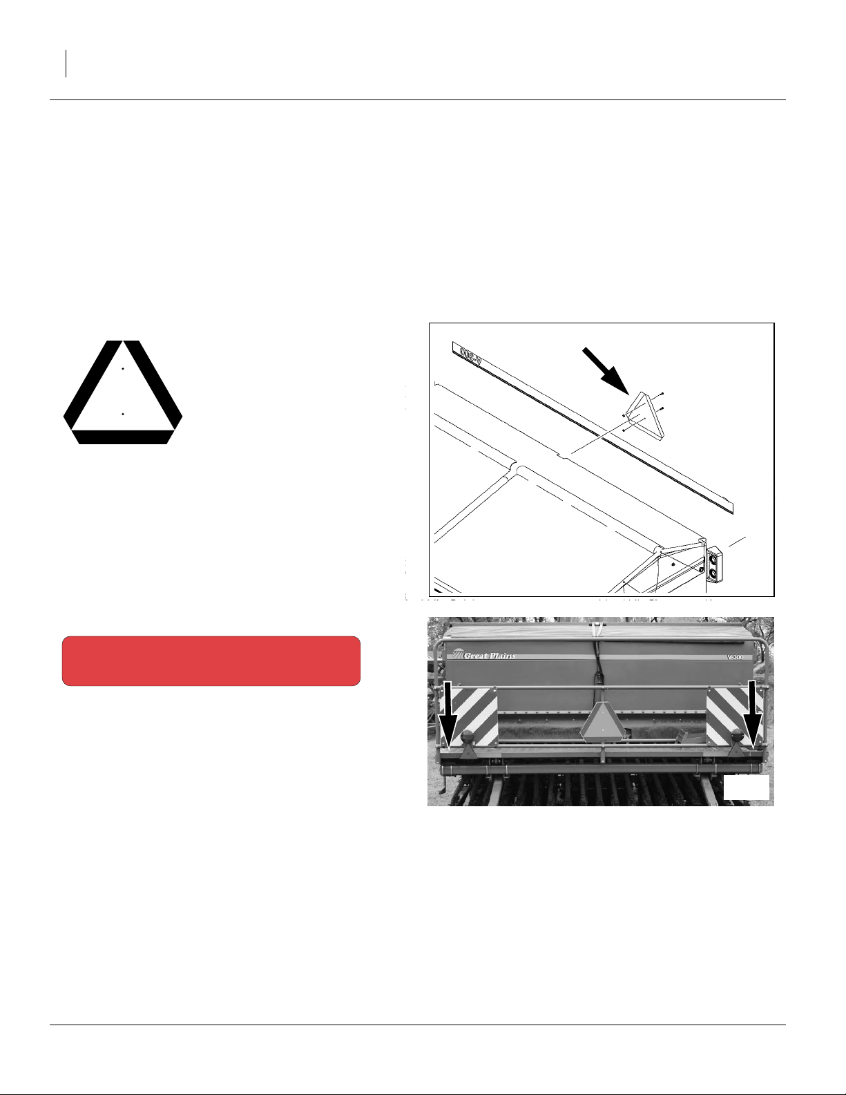
818-055C
Slow Moving Vehicle Placard
On back of seed box;
one total
838-266C
Red Reflectors
Rear face, outside ends of rear walkboard;
two total
23238
27169
148-057M-A 11/15/2007
Page 11
Great Plains Manufacturing, Inc. 7
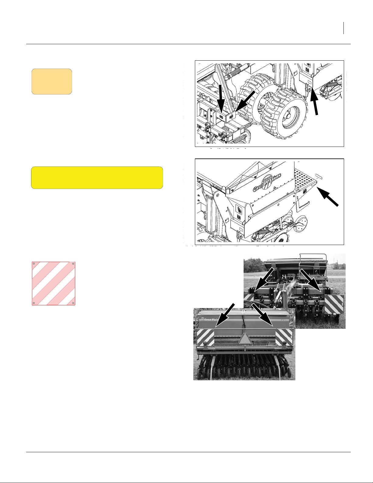
818-229C
Amber Reflectors, Half Size
Front face of hitch frame, outside ends,
Outside faces of hitch frame, both sides,
Outside faces of main frame, at front;
six total
23238
838-265C
Amber Reflectors, Full Size
Outside ends of aft walkboard;
two total
833-398C
Fluorescent Panels
2 on rear face, outside ends of rear walkboard,
2 on front face, end ends of coulter toolbar;
4 total
23238
27168
27169
11/15/2007 148-057M-A
Page 12
8 V300 & V300F Great Plains Manufacturing, Inc.
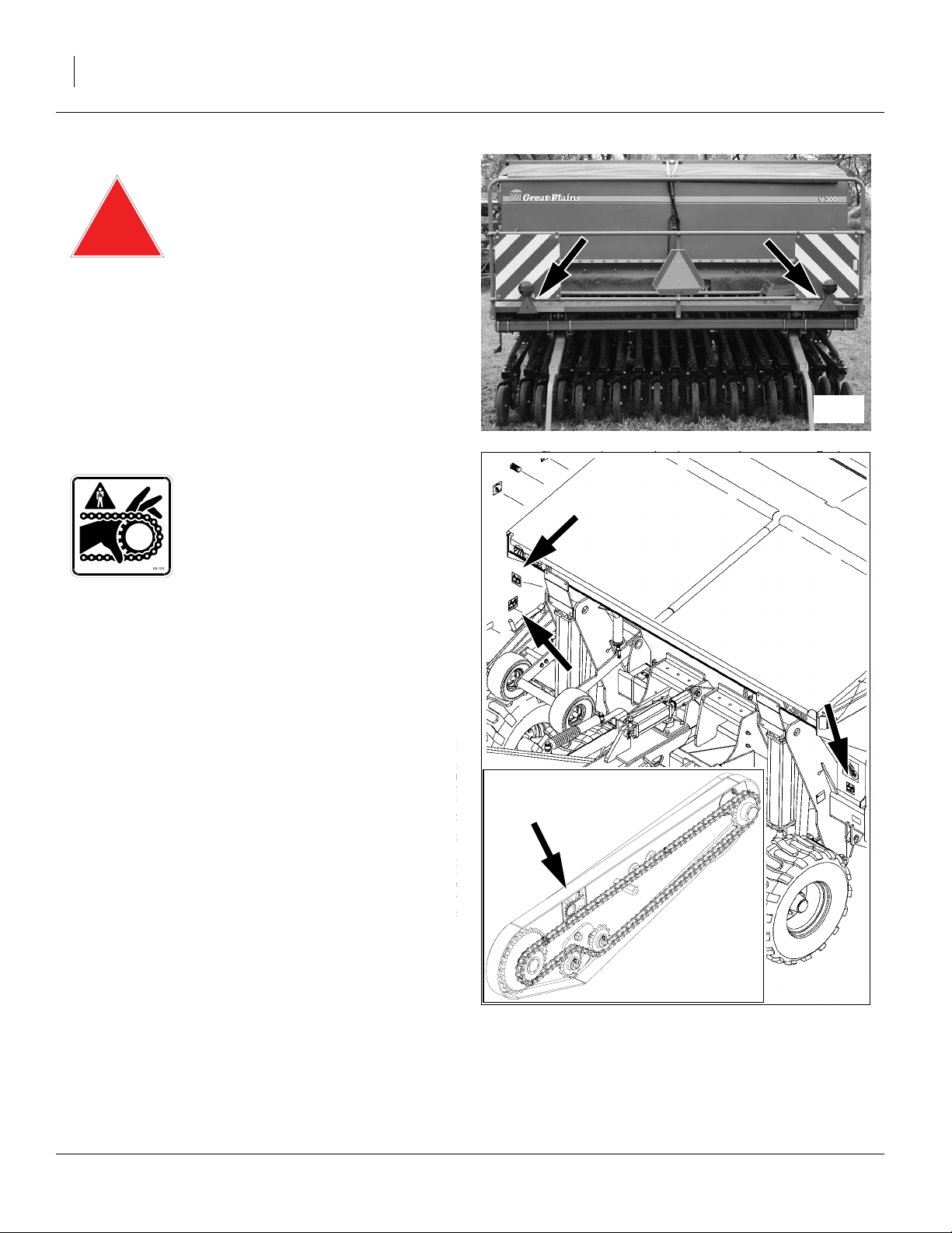
833-399C
Red Triangle Reflectors
below rear lights;
2 total
27169
838-363C
Danger: Moving Chain
Front and side of each frame post,
inside contact drive housing; five total
22639
23238
148-057M-A 11/15/2007
Page 13
Great Plains Manufacturing, Inc. 9
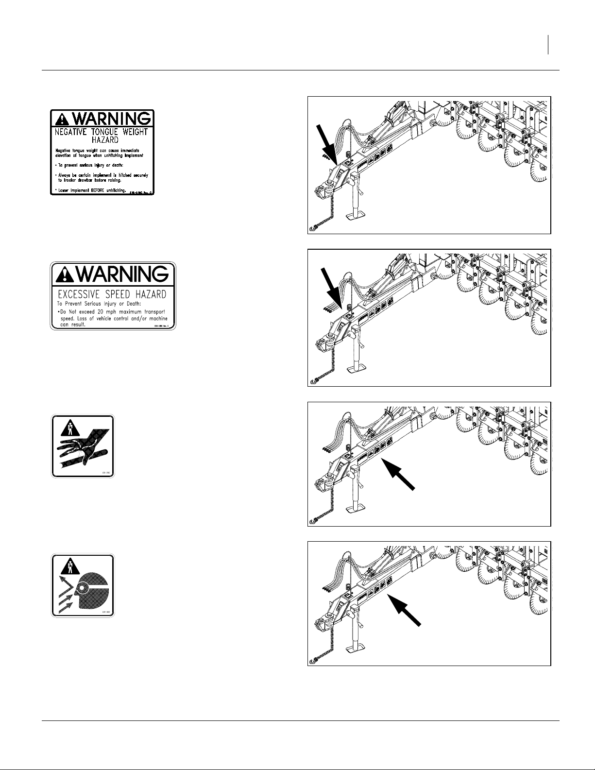
818-019C
Warning: Negative Tongue Weight
Front face of tongue at hitch;
one total
23238
818-188C
Warning: Excessive Speed Hazard
Top of tongue near hitch;
one total
838-359C
Warning: High Pressure Fluids
Left side of tongue below hitch cylinder;
one total
838-360C
23238
23238
Warning: Wear Eye Protection
Top of tongue;
one total
11/15/2007 148-057M-A
23238
Page 14

10 V300 & V300F Great Plains Manufacturing, Inc.
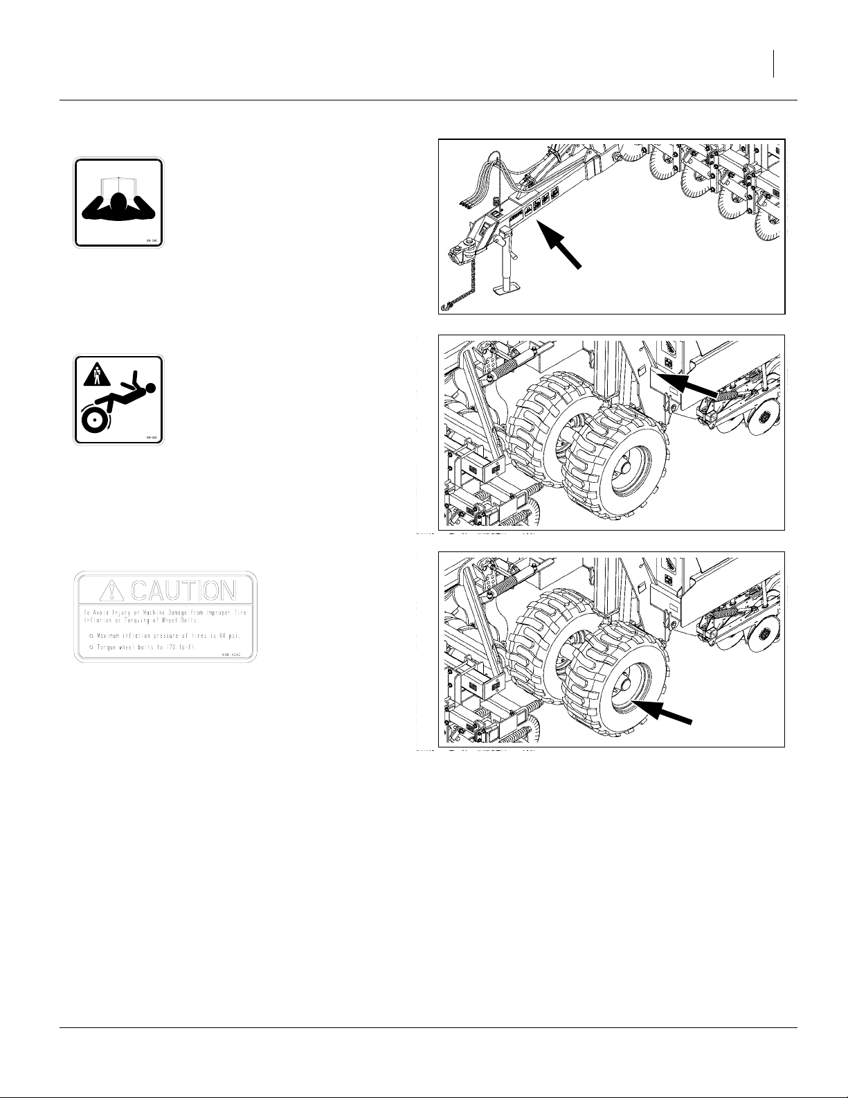
838-361C
Warning: Do Not Ride
Each end of aft walkboard,
top of tongue;
three total
23238
838-365C
Warning: Pinch/Shear
Each marker arm;
two total
838-367C
Warning: Falling Marker
Each marker arm;
two total
818-016C
21504
21504
Caution: Hitch
Left side of tongue at hitch;
one total
148-057M-A 11/15/2007
23238
Page 15
Great Plains Manufacturing, Inc. 11
838-358C
Caution: Read Manual
Left side of tongue below hitch cylinder;
one total
23238
838-362C
Caution: Tires Not A Step
Each frame post;
two total
838-426C
Caution: Tire Inflation and Torque
Each gauge wheel rim;
four total
23238
23238
11/15/2007 148-057M-A
Page 16
12 V300 & V300F Great Plains Manufacturing, Inc.
Introduction
Great Plains welcomes you to its growing family of new
product owners. This implement has been designed with
care and built by skilled workers using quality materials.
Proper setup, maintenance and safe operating practices
will help you get years of satisfactory use from the
machine.
Description of Unit
The Verti-Drill is a pull-type seeding implement. The
implement consists of a three-point drill mounted on a
center-pivot hitch. The hitch and drill are integrally connected. No-till coulters are mounted on the hitch, to
zone-till strips for seed furrows. Straight-arm openers on
the drill prepare seedbeds and place the seed. The pivoting action of the hitch helps drill openers track the
coulters. Contact-drive tires on the drill power seeding
from hitch tires. A hydraulic cylinder controls coulter
depth. Lift cylinders raise the drill for turns and transport.
The V300F model includes a separate meter system and
delivery tubes for fertilizer, and an adjustable partition in
the seed box.
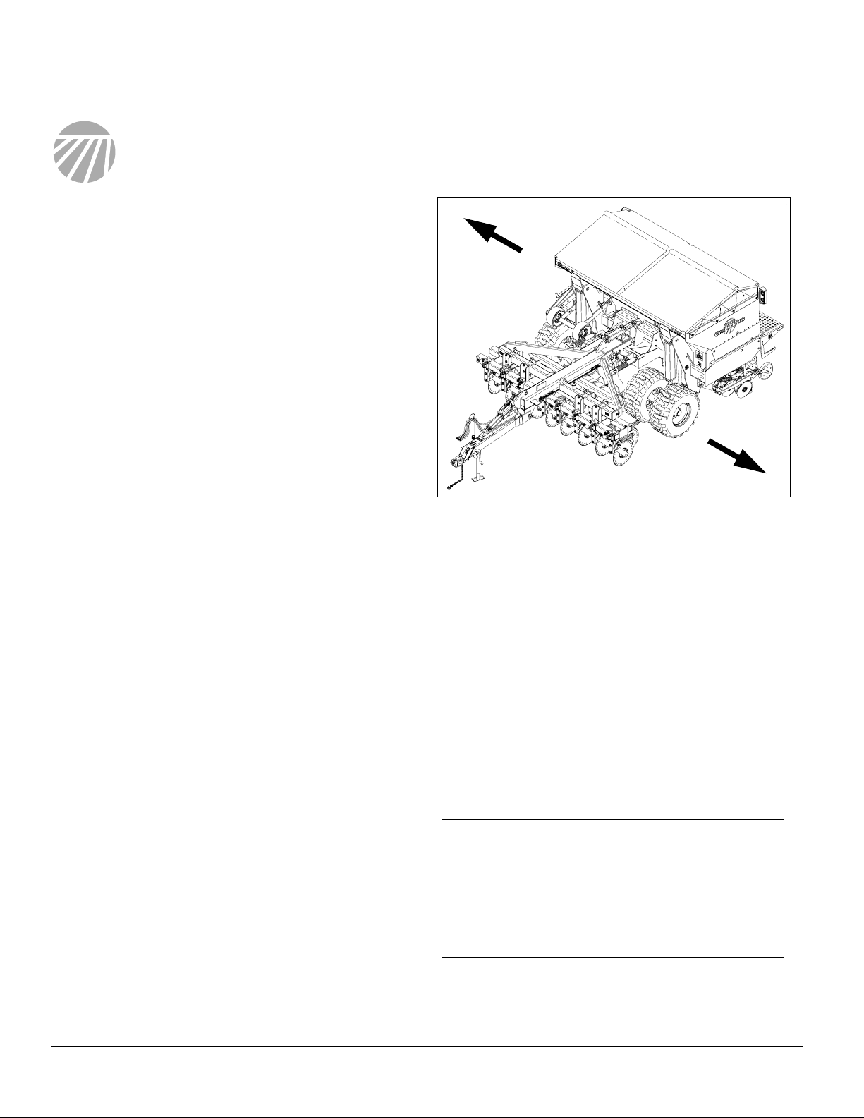
R
Figure 1
V300: Left/Right Notation
L
22574
Document Family
148-057M-A Operator Manual (this document)
148-057B Seed Rate Charts
148-057P Parts Manual
Models Covered
This manual applies to implement serial number A1043L
and higher of models:
V300-1962 3 Meter Verti-Drill
V300F-1962 3 Meter Verti-Drill with Fertilizer
Earlier model V300 drills are covered by Operator Manual 148-057M.
Intended Usage
Use this implement for seeding production-agriculture
crops only. Do not modify implement for use with attachments other than those specified by Great Plains. Use
implement in no-till or minimum tillage conditions.
Using This Manual
This manual familiarizes you with safety, assembly, operation, adjustments, troubleshooting and maintenance.
Read this manual and follow the recommendations to
help ensure safe and efficient operation.
The information in this manual is current at printing.
Some parts may change to assure top performance.
Definitions
The following terms are used throughout this manual.
Right-hand and left-hand as used in this manual are
determined by facing the direction the machine will travel
while in use unless otherwise stated.
IMPORTANT !
Paragraphs in this format present a crucial point of
information related to the current topic.
Read and follow the directions to:
- remain safe,
- avoid serious damage to equipment and
- ensure desired field results.
Note: Paragraphs in this format provide useful informa-
tion related to the current topic.
148-057M-A 11/15/2007
Page 17
Great Plains Manufacturing, Inc. Introduction 13
Owner Assistance
If you need customer service or repair parts, contact a
Great Plains dealer. They have trained personnel, repair
parts and equipment specially designed for Great Plains
products.
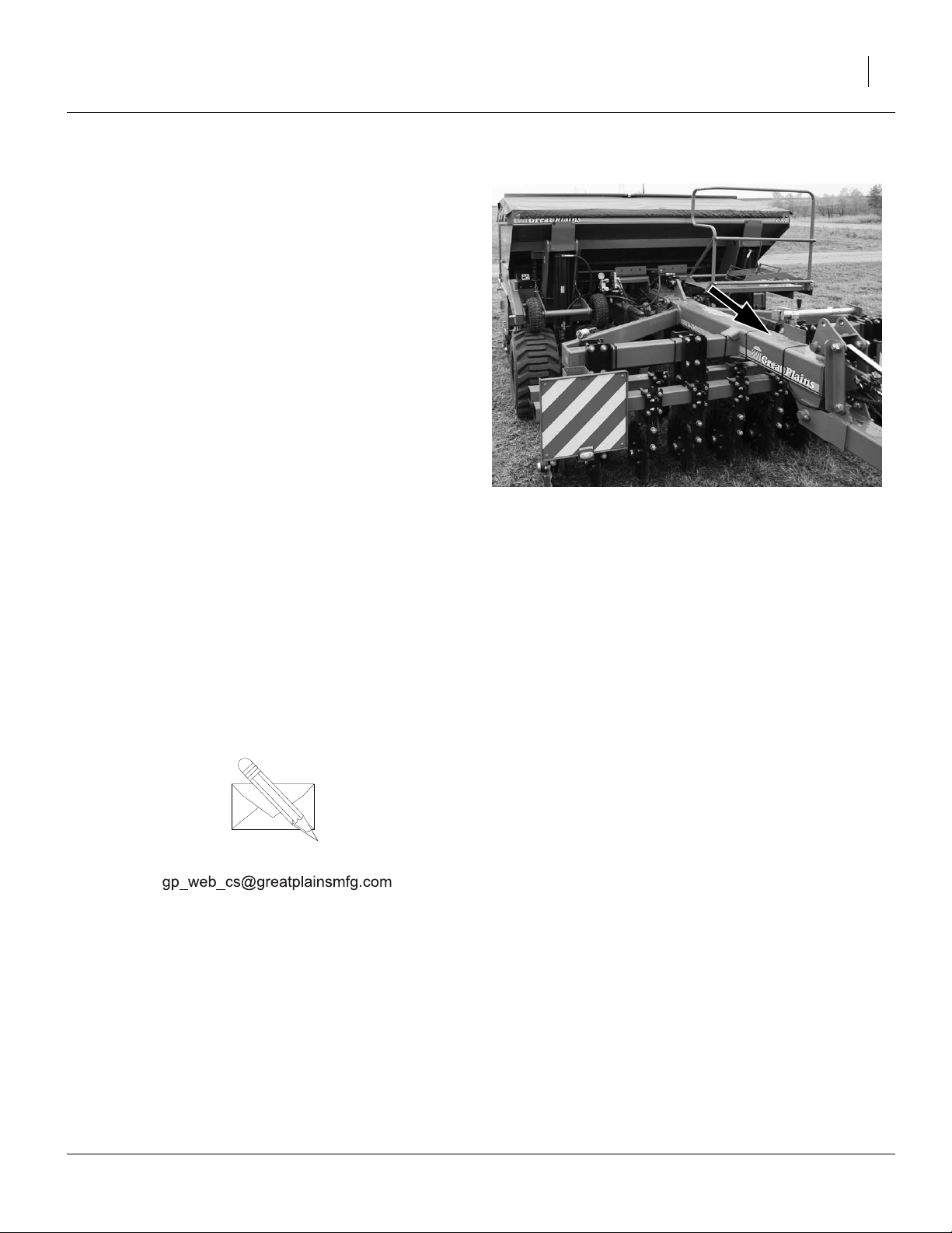
Refer to Figure 2
Your machine’s parts were specially designed and
should only be replaced with Great Plains parts. Always
use the serial and model number when ordering parts
from your Great Plains dealer. The serial-number plate is
located on the top of the hitch frame.
Record your drill model and serial number here for quick
reference:
Model Number:__________________________
Serial Number: __________________________
Your Great Plains dealer wants you to be satisfied with
your new machine. If you do not understand any part of
this manual or are not satisfied with the service received,
please take the following actions.
1. Discuss the matter with your dealership service
manager. Make sure they are aware of any problems
so they can assist you.
2. If you are still unsatisfied, seek out the owner or general manager of the dealership.
For further assistance write to:
Figure 2
Serial Number Plate
27170
Product Support
Great Plains Mfg. Inc., Service Department
PO Box 5060
Salina, KS 67402-5060
785-823-3276
11/15/2007 148-057M-A
Page 18

14 V300 & V300F Great Plains Manufacturing, Inc.
Setup
This section covers steps performed during or prior to
first hitch, and on routine re-hitch.
First hitch may entail equipment installation, some
assembly or even some re-wiring. Review the entire section prior to first hitch to ensure that all necessary components and tools are at hand.
Pre-Start Checklist
1. Read and understand “Important Safety Information” on page 1.
2. Check that all working parts are moving freely, bolts
are tight, and cotter pins are spread.
3. Check that all grease fittings are in place and lubricated. Refer to “Lubrication” on page 104.
4. Check that all safety decals and reflectors are correctly located and legible. Replace if damaged.
“Safety Decals and Reflectors” on page 6.
5. Inflate tires to pressure recommended and tighten
wheel bolts as specified. See “Appendix” on
page 114.
Negative Tongue Weight
!
WARNING
This drill can have positive and negative tongue weight, and
the tongue weight can change significantly between hitching
and unhitching, as materials and/or weights are added,
applied or removed.
The changing tongue weight can also tend to work the
hitch pin loose during transport and field operations. To
avoid serious injury or death resulting from a suddenly
elevating hitch or a traffic accident, always observe these
rules:
▲ Always use the clevis hitch provided, securely fastened to
the tractor drawbar with both bolts.
▲ Always pin the hitch pin.
▲ Always hitch before connecting hydraulics.
▲ Always lower the openers before unhitching.
▲ Always use the jackstand during unhitching.
148-057M-A 11/15/2007
Page 19

Great Plains Manufacturing, Inc. Setup 15
Hitching Tractor to Implement
!
DANGER
You may be severely injured or killed by being crushed
between the tractor and drill. Do not stand or place any part of
your body between drill and moving tractor. Stop tractor
engine and set park brake before installing pins.
4
IMPORTANT !
The standard model V300 and V300F require a tractor
with “Closed Center” hydraulics. If the intended tractor
has “Open Center” hydraulics, the drill requires a kit to
convert it to open center operation. Have your Great
Plains dealer contact the factory.
Refer to Figure 3
1. Place hitch weldment over ball swivel on hitch
tongue . Hold hitch weldment in place by inserting
spacer tube through weldment clevis and ball
swivel.
2. Back tractor up to hitch and align rear drawbar hole
with spacer tube.
Refer to Figure 4
3. Bolt hitch weldment to tractor drawbar using
the larger 1-8x10 bolt ,
large (1in) flat washer ,
lock washer ,
and nut .
4. Insert the smaller
through the
then the slotted hole of the weldment,
the forward (secondary) hole of tractor drawbar.
5. Secure with
3
⁄
4
and nut .
6. Tighten both bolts to specified torque
(see “Torque Values” on page 115).
7. Securely attach safety chain to tractor-drawbar
frame.
3
4
3
2
3
⁄
in flat washer ,
4
in lock washer
8
1 2
1
4
3
⁄
-10x9-inch bolt
4
6
7
5
1
9
3
2
5
Figure 3
Hitch Components
5
1
17215
6
7
4
3
8
2
Figure 4
Securing Hitch
11/15/2007 148-057M-A
17215
Page 20
16 V300 & V300F Great Plains Manufacturing, Inc.
Refer to Figure 5
8. Un-pin jack from side of hitch tongue. Pin in transport/storage location on left top hitch tool bar.
9. If the tractor drawbar height is adjustable, and the
desired value is known, set it now. Otherwise, implement (and as necessary, tractor drawbar height) are
adjusted when setting coulter depth (see page 71).
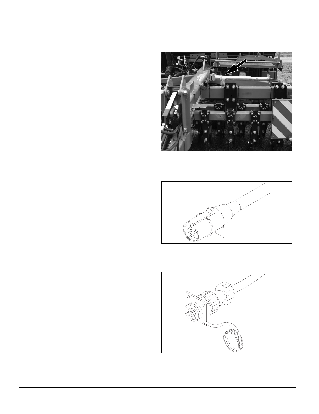
Electrical Connections
The V300 & V300F lighting harness has a Europeanstyle 7-pin lighting connector as standard equipment. If
your tractor has an ASAE connector, contact your dealer
for a replacement connector.
The V300 & V300F include a digital seed monitor as
standard equipment. Prior to first use, the display module
must be installed in the tractor (see “Monitor Installa-
tion” on page 18).
Refer to Figure 6 and Figure 7
If the lighting connector is already compatible with the
tractor, and the monitor console is installed on the tractor, make the following connections:
• lighting
• monitor
Figure 5
Jack in Transport Position
Figure 6
Lighting Connector
27277
27172
Figure 7
27173
Monitor Connector
148-057M-A 11/15/2007
Page 21
Great Plains Manufacturing, Inc. Setup 17
Hydraulic Connections
!
WARNING
Escaping fluid under pressure can have sufficient force to penetrate the skin. Check all hydraulic lines and hoses before
applying pressure. Fluid escaping from a very small hole can
be almost invisible. Use paper or cardboard, not body parts, to
check for suspected leaks. If injured, seek medical assistance
from a doctor that is familiar with this kind of injury. Foreign
fluids in the tissue must be surgically removed within a few
hours or gangrene will result.
Only trained personnel should work on system hydraulics!
Great Plains hydraulic hoses are color coded to help you
hook-up hoses to your tractor outlets. Hoses that go to
the same remote valve are marked with the same color.
The drill consumes hydraulic power for two or three circuits.
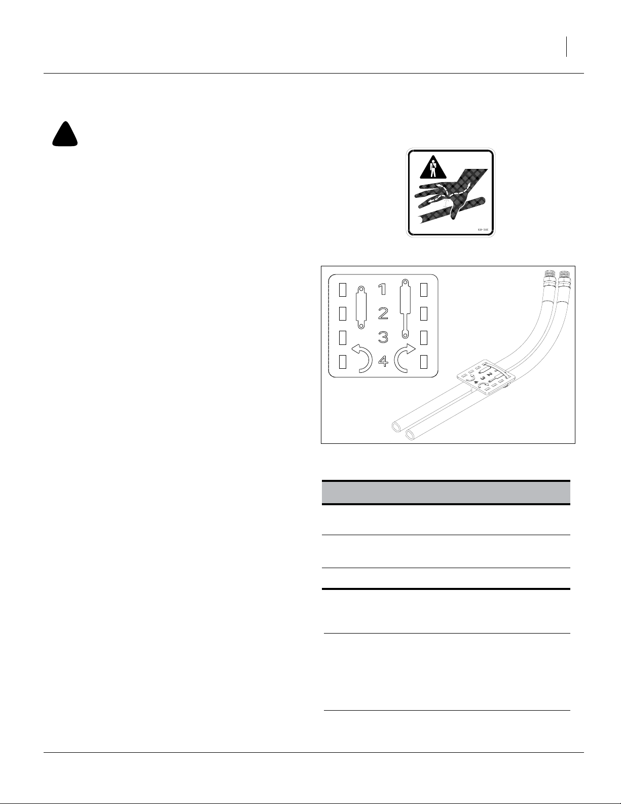
Refer to Figure 8
To distinguish hoses on the same hydraulic circuit, refer
to plastic hose label. The hose under an extended-cylinder symbol feeds a cylinder base end. The hose under a
retracted-cylinder symbol feeds a cylinder rod end.
Make sure all tractor levers are in neutral or float, or tractor hydraulics are off, before making connections.
Note: If the tractor has only one circuit capable of provid-
ing continuous flow, connect the Lift/Lower drill circuit (Red) to that tractor circuit.
Note: If the tractor circuit can onlybe locked incontinuous
flow at one end of the lever travel, connect the drill’s
Lift/Lower Retract/“base end” to that side of the
tractor circuit.
Hydraulic Charge and Bleed
The V300 and V300F is normally shipped with the
hydraulic hoses disconnected. They are installed by your
dealer, but the hydraulic system may not have been
charged and bled.
If there is any question about the possibility of air in the
hydraulic system, bleed all the systems per the instructions beginning on page 96.
If the system has not been charged, have 11.3 liters (3.5
gallons) of hydraulic oil available for refilling the tractor
reservoir.
Figure 8
Plastic Hose Label
817-348c
17641
Color V300 Hydraulic Function
Red Transport Lift and
Hydraulic Down-Pressure
Blue Tongue Height
Markers (see footnote*)
<none>
* Markers are optional. Standard markers are on a
dedicated circuit. An optional selector valve is
available, and shares the tongue circuit.
The standard model V300 and V300F require a tractor with “Closed Center” hydraulics. If the intended
tractor has “Open Center” hydraulics, the drill
requires a kit to convert it to open center operation.
Have your Great Plains dealer contact the factory.
Markers
*
IMPORTANT !
11/15/2007 148-057M-A
Page 22
18 V300 & V300F Great Plains Manufacturing, Inc.
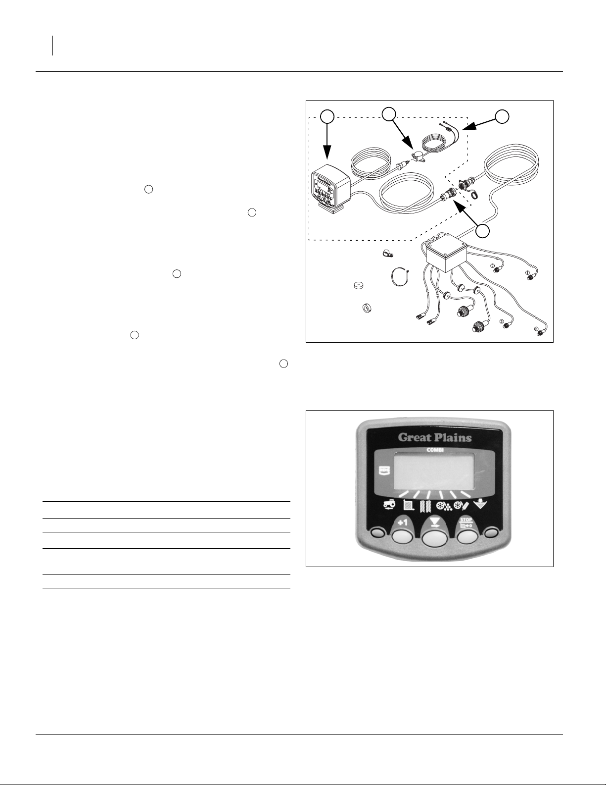
Monitor Installation
Refer to Figure 9
1 3
Drill-mounted components of the seed monitor are preinstalled. The system includes tractor-mounted components (in dashed outline) that must be installed in the
tractor prior to first use.
4
1. Mount the console where it will be visible to the
tractor driver, and not interfere with safe operations.
Make sure the location allows the harness to
reach the hitch.
Remove the protective film from the monitor face
after installation.
2. Connect the power leads to tractor battery power.
The wiring color code is:
+ Brown
- Blue
The console includes its own power switch.
3. The power jack is weather-proof, and may be
mounted inside or outside of the tractor cab.
4. After hitching, connect the tractor monitor harness
to the drill harness.
1
2
3
4
2
Monitor Setup
The seed monitor requires entry of data that rarely
changes, and data that changes for each planting session. See “Monitor Operation” on page 43 for step-bystep data entry and programming instructions.
Most of the monitor setup can be done with the drill disconnected. The harness to the drill does need to be connected for speed Autocal.
Figure 9
Seed Monitor System
2
22985
Units of measure:
Width: 3.0m or 118.1in
S.S.F.†:
Fertilizer Shaft
Rate
Tramlining: On or Off
* Use Imperial for U.S. customary units.
† Speed Sensor Factor is the relationship between
sensor counts and implement forward speed. AutoCal is recommended for most accurate reporting.
Metric or Imperial
3.235 (metric) or 127.4 (imperial)
3.000 (factory default) on V300F
0.000 (alarm disabled) on V300
*
Figure 10
Seed Monitor Console
22632
Install Other Options
Some options and accessories are not pre-installed prior
to delivery. Install them prior to first use.
148-057M-A 11/15/2007
Page 23

Great Plains Manufacturing, Inc. Setup 19
Leveling Drill
Before planting, check drill level, using the coulter depth,
opener down-force and planting depth you expect to use.
Perform this setup on level ground with conditions similar
to the planting ground.
Several interrelated adjustments control depth and level.
Check/set them in this order to most quickly “zero in” on
the desired field results. This setup is representative of
results mid-session. The drill weighs more with a full
seed and fertilizer load, and less when near empty, so
check results early and late in the planting.
Leveling Order Summary
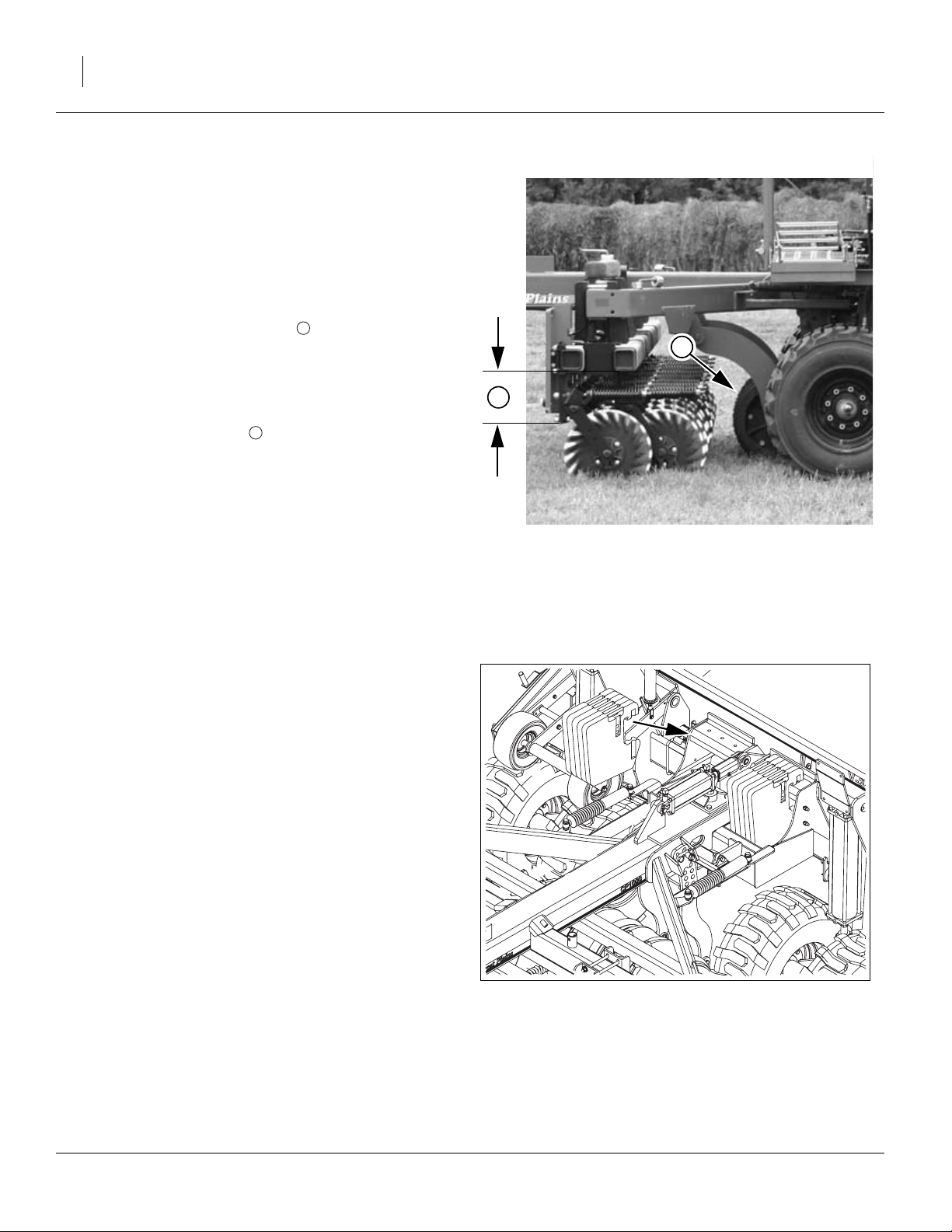
Refer to Figure 11
1. Check tires, mounts and blades.
2. Add weight to drill. Disable seeding.
3. Set initial seeding depth.
4. Set initial lift cylinder stops and down-pressure.
5. Set initial hitch height.
6. Lower drill, pull forward in planting conditions.
Check levels and depths.
7. Adjust hydraulic hitch to set coulter depth. Field
check.
8. Adjust lift spacers to level hitch. Field check.
9. Adjust press wheels to set seeding depth. Field
check.
10. Adjust hydraulic down-pressure for opener depth.
Field check.
11. Review all settings starting at step 7.
Figure 11
Checking Level
27204
11/15/2007 148-057M-A
Page 24
20 V300 & V300F Great Plains Manufacturing, Inc.
Check Tires, Blades & Mounts
Always inflate tires to factory specifications before making any of these adjustments.
Prior to first use, check coulter mounts to ensure that
coulters are at the correct nominal height. Periodically recheck disk blades. As blades wear, the coulters will not
cut as deep.
Refer to Figure 12
With the drill raised, the distance from the bottom of
the tool bar to the bottom of the pivot casting is:
28.26mm (11.13in).
To adjust one or more coulters, see “Coulter Adjust-
ments” on page 71.
1
2
1
Check that packer wheels are not hitting their bottom
stop pins. See page 28 for adjustment.
Periodically check the opener disk blades. As blade
wear, the furrow will not be as deep. Adjust the T-handle
setting to maintain a constant seeding depth. See
“Opener Depth (Press Wheel Height)” on page 93.
In addition, worn blades will not have correct contact.
See “Disk Blade Adjustments” on page 91 for blade
contact adjustments.
2
Disable Seeding & Weight Drill
Disable Seeding
To avoid unnecessary wear on the drive system during
setup, disengage the main drive clutch (see See “Main
Box Drive Clutch” on page 77), and on V300F, disengage the fertilizer clutch (page 86).
If using seed for test weight in the main seed box or fertilizer box, it is important to prevent it from being metered,
(or leaking through the meters, which can happen even if
the shafts do not turn). Set the main box seed rate handle to 0. On model V300F, also set the fertilizer rate
adjuster to 0.
Adjust at Half Material Weight
To properly set depths and down-pressures, the drill
needs to weigh approximately what it will weigh halfway
through a planting session. This can be done with material in the seed/fertilizer boxes, or by using extra weights.
However, if the planting is with the Small Seeds box, the
weight is low enough that no simulation is necessary.
If you will not be using extra weights on the drill when
planting, but have “suitcase” weights available, material
weight can be simulated with weights on the weight
brackets. Note that fully loading both brackets may still
be significantly less than half a full material load.
Figure 12
Coulter Height
Figure 13
Adding Weights
27208
27229
148-057M-A 11/15/2007
Page 25
Great Plains Manufacturing, Inc. Setup 21
Initial Seeding Depth
Refer to Figure 14
If the drill has been used for planting, leave the row unit
T-handles at their present settings.
If the drill has not been used before, initially set all T-handles to the middle holes in their range.
The T-handle on the row unit is the primary adjustment
for seeding depth when:
• the coulters prepare the ground ahead of the furrow,
• the down-pressure is appropriate for conditions, and
Figure 14
Initial T-Handle Setting
15659
• the row unit is running level,
The T-handle controls the relationship between opener
blade and press wheel height. See page 93 for adjustments.
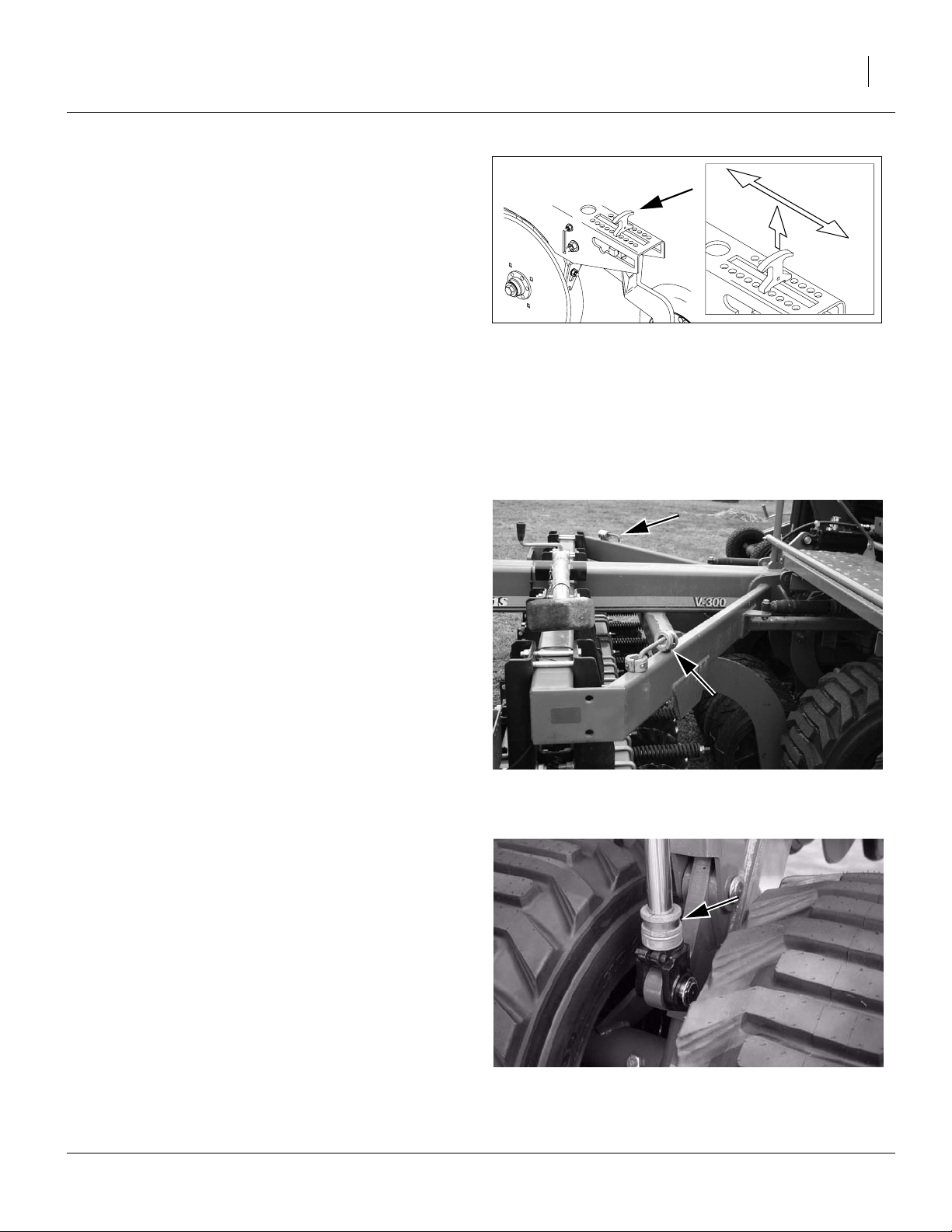
Initial Lift Cylinder Spacers
Refer to Figure 15 and Figure 16
Raise the drill. If spacers (cylinder stop bushings) are
already present on the lift cylinder rods, they were placed
there during a previous leveling, and may be left as is.
If there are no spacers on the rods, make sure both sets
of five sizes are available on the rod loops on top of the
hitch wing rear tubes.
Raise the drill and install the 5.1cm (2in) spacers. These
are spring-loaded half rings, and snap around the rod.
Figure 15
Cylinder Spacer Storage
27207
Figure 16
22622
Cylinder Stop Bushing (Spacer)
11/15/2007 148-057M-A
Page 26
22 V300 & V300F Great Plains Manufacturing, Inc.
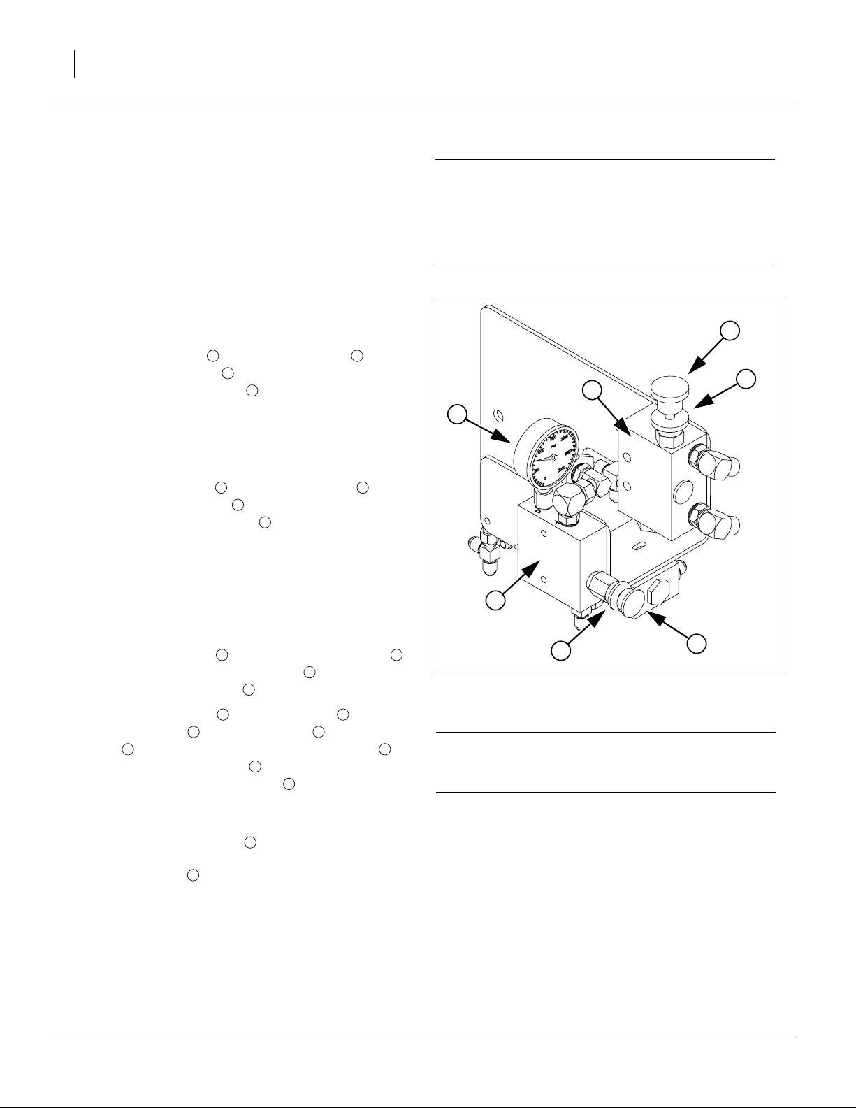
Initial Down-Pressure
If the down-pressure valve has been previously set for
field operations, leave it as is.
If this is the first use of the drill, calibrate the bypass
valve and set the initial pressure to 800 psi.
Set or Calibrate Bypass
Refer to “Lift/Lower Operations” on page 35 to know
what to expect the drill to do as hydraulics are cycled.
Set Bypass for PC Closed
Tractors with Pressure Compensating Closed Center
Hydraulics:
• Release locking disk . Close bypass valve for no
oil flow by turning knob on valve clockwise completely. Tighten locking disk . Always operate the drill
1 2
3
1
with the bypass valve closed.
Set Bypass for LS Closed/PFC
Tractors with Load Sensing Closed Center or Pressure
Flow Compensating Hydraulic Systems:
The standard model V300 and V300F require a tractor with “Closed Center” hydraulics. If the intended
tractor has “Open Center” hydraulics, the drill requires
a kit to convert it to open center operation. Have your
Great Plains dealer contact the factory.
7
IMPORTANT !
2
3
1
1. Release locking disk . Close bypass valve for no
oil flow by turning knob on valve clockwise completely. Tighten locking disk .
1 2
3
1
2. With tractor at half throttle, adjust flow-control valve
on tractor so openers raise and lower at a reasonable speed. Keep tractor at one-half throttle for
remaining steps.
3. Engage tractor hydraulics and lower openers. Lock
hydraulic lever on tractor for continuous operation.
4. Release locking disk on pressure control valve .
Adjust pressure-control valve knob for opener
down pressure so gauge is at 1800 psi.
5. Release locking disk on bypass valve . While
watching gauge , slowly turn knob on bypass
2 2
valve counterclockwise. Adjust bypass valve
just until needle on gauge begins to move down
from 1800 psi. Use locking disk to lock bypass
4 5
6
7
1 2
7 3
7
1
valve at this setting. (See also note at right.)
Set Down Pressure
Adjust pressure-control valve to desired opener down
5
pressure per “Hydraulic Down Pressure” on page 36.
Tighten locking disk .
4
While 1800 psi is a good starting point for setting the
bypass valve, if you consistently operate the drill with low
opener down pressure you can set the bypass valve
below 1800 psi. If you consistently operate the drill with
very high opener down pressure, you may need a
bypass-valve setting above 1800 psi.
5
4
Figure 17
Initial Down-Pressure Setting
IMPORTANT !
Failure to use the bypass valve on load-sensing tractors may cause major tractor damage.
Note: Faster opener raise/lower increases potentialfor oil
over-heating, excess wear and tractor damage.
The higher the bypass pressure, the greater the potential
for oil over-heating and tractor damage. At the same
time, for proper opener operation the bypass valve must
be set at least 300 psi above the opener down-pressure
setting when the tractor is at one-half throttle. Therefore,
you should set the bypass valve as low as possible while
staying at least 300 psi above the opener down pressure
setting.
6
27231
148-057M-A 11/15/2007
Page 27
Great Plains Manufacturing, Inc. Setup 23
Initial Hitch Height
Lowering for Leveling
Remove all transport locks (see page 31), and fully lower
drill using the lift cylinders.
Initial Hitch Height
if you have a record of the hitch height scale reading
from a recent planting session, set the height to that
value.
Otherwise, adjust the hitch until the coulter blades just
touch the ground, then lower it one half count on the
hitch stroke gauge (roughly 5cm or 2in of vertical travel
at the coulter blades).
Lower Drill, Pull Forward and Check
It is not possible to accurately set depth and force by
raising and lowering a stationary drill. It must be run in
the ground, in soil conditions as similar as possible to
those of the field to be planted.
Review lift and lower operations on page 35.
Pull forward at least the length of the tractor-plus-drill, so
that you can see the effects of all tires, the coulters,
openers and presswheels.
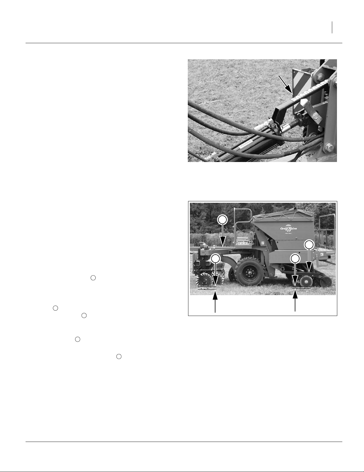
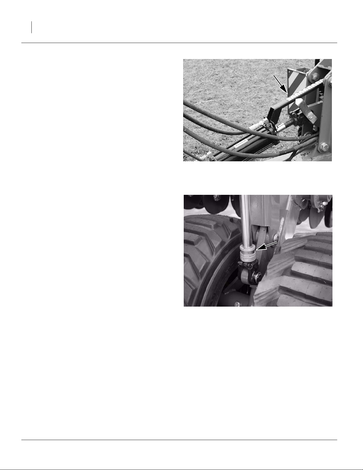
Refer to Figure 19
• Check that the hitch is level. The primary adjustment for this is lift cylinder spacers (once coulters are
at desired depth).
• Check that the coulters are running at the desired
2
depth , typically 13 to 25mm (0.5 to 1in) deeper than
the opener disks . The primary adjustment for this is
the hydraulic hitch.
• Check that the openers are running at the desired
seeding depth . The primary adjustments for this are
the row unit T-handle and the hydraulic down force.
1
3
3
Figure 18
Hitch Height Scale
27234
1
4
2
Figure 19
Checking Level, Depths
3
27208
• Check that the opener frames are level, as this provides the most consistent depth control and predictable down-force. Once all the other adjustments are
correctly tuned, the row units operate parallel to flat
ground.
11/15/2007 148-057M-A
4
Page 28
24 V300 & V300F Great Plains Manufacturing, Inc.
Hydraulic Hitch Adjustment
The hydraulic hitch is the primary means of adjusting
coulter depth.
Making changes to hitch height also affects hitch level,
requiring spacer changes at the lift cylinders. If the hitch
was already level, make about half the needed coulter
depth change via hitch height. The compensating level
adjustment with lift cylinder spacers makes the rest of
the coulter depth change.
After adjusting the hitch height and spacers, check the
new setting for depth.
Once the depth and level are satisfactory, record the
reading on the stroke scale.
Lift Spacer Adjustments
Refer to Figure 21
The height of the rear end of the hitch is determined by
the implement lift cylinders. The drill includes two sets of
five (ten total) spacers (cylinder stop bushings) that are
used to raise the “down” position of the lift cylinders.
These spacers are provided in five different sizes, and
are used in identical combinations on both sides of the
drill. They are stored on rod loops on the hitch wings
(see Figure 18 on page 23).
The combinations provide a range of spacer stack sizes
from 19 to 166mm (0.75-6.5in), in 6.35mm (0.25in) increments.
The 6.35mm change increment corresponds to a change
in coulter depth of about 3.3mm when the hitch is level.
However, if the spacers are changed, the hitch needs to
be adjusted to compensate for the depth change, and it
amplifies the change caused by the spacers.
When raising or lowering the coulter depth with the hitch
already level, add or remove spacers equal to the coulter
depth change desired. The spacers provide about half
the desired depth change, The re-leveling at the hitch
cylinder provides the other half.
Re-check depth after spacer and hitch level changes.
Figure 20
Setting Hitch Height
Figure 21
Cylinder Stop Bushing (Spacer)
27234
22622
148-057M-A 11/15/2007
Page 29
Great Plains Manufacturing, Inc. Setup 25
Marker Setup
The V300 and V300F may have optional dual folding
pass markers and dual pre-emergence/tramline markers.
Dual Marker Setup
Although dual markers may have been dealer-installed,
they may not be set to ideal extension length or optimal
operating speed. Check these items before first use.
If there is any question about the state of the marker
hydraulics, see also “Bleeding Marker Hydraulics” on
page 100.
Mark width and throw direction are adjustable.
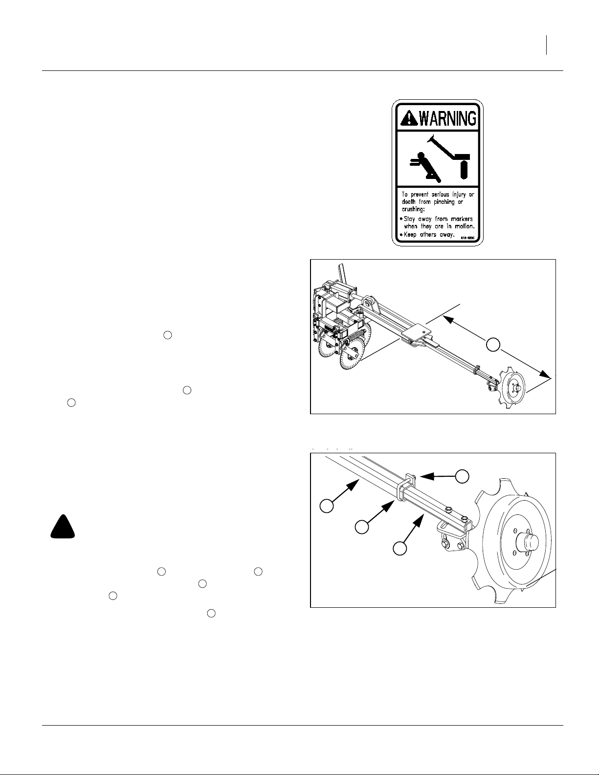
Dual Marker Extension
Refer to Figure 22
1. Extend the marker on one side.
2. Lower the drill, and pull forward a meter or so to
leave a mark with both the coulters and the marker.
3. Measure the distance from the mark left by the
outside coulter to the mark left by the marker. Measure parallel to the hitch tool bars.
For the V300 and V300F in normal configuration (all
row units in use), distance is:
1
158cm or 62.2in (
You can also measure from drill centerline to the
marker, in which case use:
3.00m or 118.2in
4. If the marker extension needs to be adjusted, first
make sure that the mark is satisfactory, as changing
the disk angle or direction changes marker extension. See “Dual Marker Disk Setup” on page 26.
Refer to Figure 23
!
CAUTION
Be careful working around marker disks. The blades are often
sharp.
5. Loosen the two nuts securing the U-bolt secur-
ing the marker tube extension in the outer marker
arm tube .
6. Slide the marker tube extension in or out as
needed, and secure nuts.
5
1
1
1
⁄
swath +
2
2 3
1
⁄
row space).
2
4
4
1
Figure 22
Marker Extension
27258
2
5
3
4
Figure 23
Marker Extension Adjustment
27259
11/15/2007 148-057M-A
Page 30
26 V300 & V300F Great Plains Manufacturing, Inc.
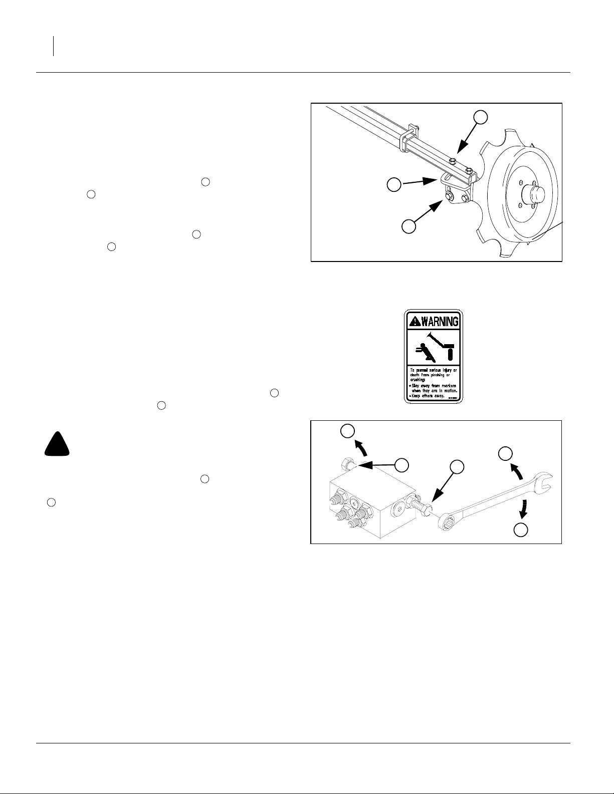
Dual Marker Disk Setup
The marker disk is adjustable for width of mark and
direction of throw. Make the adjustments with the marker
side extended to field position.
Refer to Figure 24
1. Initially set the disk to be vertical with respect to the
ground. Loosen the lower bolts in the wrist weld-
8
ment and tip the top of the disk in or out with
respect to the drill. Tighten bolts.
2. Adjust the width angle as needed to make a visible
mark. Loosen the upper nuts and adjust the wrist
weldment to the desired angle and throw direc-
tion. Tighten bolts.
3. Repeat for other marker.
Dual Marker Speed
The folding speed of sequenced dual markers is controlled by an adjustment at the sequence valve.
Excessive folding speed can damage markers and void
the warranty.
8
6
7
8
6
Figure 24
Marker Disk Setup
7
27259
Refer to Figure 25
There is one adjustment screw for unfolding speed
and one for folding speed . You can identify adjustment
screws by markings stamped in valve body.
!
WARNING
Do not adjust sequence valve while marker is in motion.
Turn adjustment screws clockwise ( : slower) to
decrease [un]folding speed and counterclockwise
F
( : faster) to increase [un]folding speed.
With tractor idling at a normal operating speed, adjust
marker folding to a safe speed. Excessive [un]folding
speed could damage markers and void the warranty.
After adjusting the folding speed, tighten jam nuts on hex
adjustment screws to hold settings.
2
S
1
S
2
Figure 25
Sequence Valve Adjustment
F
1
S
14048
148-057M-A 11/15/2007
Page 31

Great Plains Manufacturing, Inc. Setup 27
Pre-Emergence Marker Setup
Pre-emergence, or tramline markers may have been
dealer-installed, but may not be optimally set for your
intended operations.
The markers are normally set to mark directly behind row
units controlled by tramline clutches. The factory default
for tramline rows is 4 and 16 (counting from row 1 at drill
left end). However, tramline rows can be any two of 1, 4,
6, 13, 14 or 16, plus an optional third clutch on row 13.
Refer to Figure 26
The position of the mount on the tool bar also
depends on whether the marker disks are oriented to
the right of the marker arms (as shown) or to the left.
Determine disk orientation before adjusting mount location.
To adjust mount location:
1. Adjust disk if necessary (below).
1 2
3
4
1
4
3
6
5
2
2. Loosen four nuts on the U-bolts.
3. Loosen four bolts through the walkboard. If the
mount must be moved more than a few cm, remove
these bolts entirely.
4. Slide the mount until the disk blade is directly in
line with the opener controlled by the tramline clutch.
5. Re-insert the walkboard bolts if removed.
6. Tighten the U-bolt nuts and the walkboard bolts.
Tramline Marker Disk Setup
Refer to Figure 27
The marker disks can be installed on either side of the
marker arm (by reversing the wrist weldment ), and at
arbitrary vertical and horizontal angles.
1. Using the lower bolts , initially set the vertical angle
of the disk to perpendicular to the ground. Adjust it
later if the available range of horizontal angles does
not produce a satisfactory mark.
2. Using the upper bolts , adjust the horizontal angle
to produce a mark of the desired width. Pivot forward
to throw dirt out. Pivot aft to throw dirt in.
To reverse the disk entirely, remove the upper bolts and
rotate the wrist one half turn.
After any adjustments, make sure the mark centerline is
still aligned with the tramline row opener.
6
6
1 3
3
7
8
9
Figure 26
Tramline Marker Spacing
4
9
7
8
Figure 27
Tramline Marker Disk Angle
25005
3
22620
11/15/2007 148-057M-A
Page 32

28 V300 & V300F Great Plains Manufacturing, Inc.
Packer Setup
Refer to Figure 28
The optional packer arm kit as supplied by Great Plains
does not include the packer assembly (wheels and
tires). Your dealer can install the packer arms only if the
packer assembly is also available during installation.
1
The packer arms have movable stop pins ( and ),
which limit the travel of the packer adjustment arms in
the adjustment arm weldment . Setting the pins
5
2 3
4
depends in part on your field conditions and tillage practices.
Note: Should the pins fall out or be lost, limit bolts are
6
also present in the topmost arm hole, to prevent the
packer from striking the ground when the drill is
raised. Do not remove bolts. Replace lost pins.
Before setting up the packer, decide if you intend to let
the packers rely strictly on their own weight, or carry
some of the weight of the drill.
To adjust the packer, hitch the drill and, if not already
completed, perform the leveling (page 19). Leave any
extra weights or seed load present. Move the drill to level
ground similar to expected field conditions.
1. Lower the drill and remove the upper stop pins .
2
Raise the drill, install lift locks, and remove the lower
stop pins .
3
2. Lower the drill until the presswheels just contact the
ground. Note the lowest fully exposed hole in the
adjustment arm just above the adjustment arm
weldment .
3. Lower the drill and insert the top pins in the next
4
5
2
lower hole on each side.
Note: The packer wheel now raises to the same clear-
ance as the press wheels. If the packer is not following into deeper field depressions, the pins can
be moved up to increase the downward range. Do
not set the pins so high that the packer can strike
the ground during transport.
4. If you intend to have the packers rely only on their
own weight, insert the lower pins in the lowest
holes of the adjustment arms . Skip the remaining
3
4
steps below.
If you intend to have the packers carry some drill weight,
continue with step 5.
5
6
4
2
3
1
Figure 28
Packer Stops
5. Lower the drill and pull forward 3 meters or so.
Check that the hitch is level, and that coulter depth
and opener depth are as intended.
6. Insert the lower pins in the highest available holes
2
just beneath the adjustment weldment .
7. Raise the drill, and move the pins up by:
one hole increment to transfer a small weight, or
two hole increments to transfer significant weight.
8. Lower the drill, pull forward, and check:
packers not excessively compressed
hitch level
coulters at correct depth
openers at correct depth
gauge wheels have adequate traction
27260
5
148-057M-A 11/15/2007
Page 33

Great Plains Manufacturing, Inc. Setup 29
Harrow Setup
Before first use, check the height and the tine angle of
the harrow.
Harrow Height Setup
1
Refer to Figure 29
1. Lower the drill. If the harrow is locked up, remove the
1 2
pins securing the harrow lockup to the chains.
Lay the lockup down on the harrow arm .
2. Raise the drill and insert lift locks.
3. Measure the distance from the bottom of the press
wheels to the ground.
4. Lift the harrow until the lowest tine ends are at this
same height.
5. Relocate the clevis on each chain until the harrow
is supported at this height.
4
3
Harrow Tine Setup
The setup shown in Figure 30 has proven successful in
no-till and minimum till conditions. Your field conditions
may require adjustment due to soil type, residue type
and amount, and moisture levels.
To set the tines to factory-recommended values:
Refer to Figure 29 and Figure 30
1. Lower the drill to field position and pull forward.
2. Loosen the eight nuts on U-bolts securing the arm
to the tine assembly.
3. Rotate the assembly until the front frame tube is
higher than the rear frame tube by:
elevation : 2.5cm or 1in.
Tighten the nuts.
4. Loosen the 4 nuts securing the front frame tube
to the tube support.
5. Rotate the front tube to:
tine angle : 35°
Tighten the nuts.
7
8
5
F
R
6 F
4
2
3
5
6
Figure 29
Harrow Chain Setup
27261
5
6
F
R
7
8
6. Loosen the 4 nuts securing the rear frame tube
to the tube support.
7. Rotate the rear tube to:
tine angle : 45°
Tighten the nuts.
8. Re-check the height when lifted.
11/15/2007 148-057M-A
9
6 R
9
Figure 30
Harrow Tine Setup
14612
Page 34

30 V300 & V300F Great Plains Manufacturing, Inc.
Operations
This section covers general operating procedures. Experience, machine familiarity and the following information
will lead to efficient operation and good working habits.
Always operate farm machinery with safety in mind.
Pre-Start Checklist
!
WARNING
Escaping fluid under pressure can have sufficient pressure to
penetrate the skin. Check all hydraulic lines and fittings before
applying pressure. Fluid escaping from a very small hole can
be almost invisible. Use paper or cardboard, not body parts,
and wear heavy gloves to check for suspected leaks. If injured,
seek medical assistance from a doctor that is familiar with this
type of injury. Foreign fluids in the tissue must be surgically
removed within a few hours or gangrene will result.
1. Review the entire section “Important Safety Information” on page 1.
2. Lubricate the drill as per “Lubrication” on page 104.
3. Check all tires for proper inflation per “Tire Inflation
Chart” on page 114.
4. Check all bolts, pins and fasteners. Torque as specified per “Torque Values” on page 115.
5. Check implement for worn or damaged parts. Repair
or replace before going to the field.
6. Check hydraulic hoses, fittings and cylinders for
leaks. Repair or replace before going to the field.
7. Check seed monitor setup and ensure that the drill
configuration data is loaded, prior to entering data for
the current planting session.
Transport
Unload seed box before transporting if at all possible.
The implement can be transported with a full box of
grain, but added weight will increase stopping distance
and decrease manoeuvrability. Some seed loss may also
occur, as even when set to zero and not rotating, the
meters do not completely block flow.
!
WARNING
Towing the implement at high speeds or with a vehicle that is
not heavy enough can lead to loss of vehicle control. Loss of
vehicle control can lead to serious road accidents, injury and
death. To reduce the hazard:
148-057M-A 11/15/2007
A
Page 35

Great Plains Manufacturing, Inc. Operations 31
1. Select a suitable tractor. Do not tow an implement
that, when fully loaded, weighs more than 1.5 times
the weight of the towing vehicle. Some reference
weights are given below.
Drill Configuration
V300 V300F
kg lbs kg lbs
Base drill configuration, no options, empty 3968 8747 4188 9233
add for full main seed load + 2542 + 5604 + 1002 + 2209
add for full fertilizer load -0- -0- + 2055 + 4531
add for (18) maximum extra weights + 816 + 1800 + 816 + 1800
add for Dual Markers + 340 + 749 + 340 + 749
add for Packer + 154 + 339 + 154 + 339
add for Small Seeds Option + 128 + 283 + 128 + 283
add for Tramline Marker + 163 + 359 + 163 + 359
add for Harrow + 94 + 208 + 94 + 208
Your configuration
Maximum configuration 9189 20258 9584 21128
2. Hitch to the tractor. See “Hitching Tractor to Imple-
ment” on page 15. Make sure safety chain is
secured to tractor.
3. Check that tires are properly inflated. See “Tire
Inflation Chart” on page 114.
Lift Cylinder Locks
Refer to Figure 31
4. Hydraulically raise drill with transport-lift cylinders,
aligning the slotted hole in the lock channel with the
hole in the lug.
5. Install pins in lift cylinder locks.
Figure 31
Lift Cylinder Lock
22604
Down Pressure Cylinder Lock
Refer to Figure 32
Note: The lock channel on the down pressure cylinder is
part of the down pressure system and is never removed. Leave the bolt in place.
6. If folding markers are installed, check that they are
completely folded. If they are on a circuit with a
selector valve, set the valve to the tongue circuit
when markers are fully folded.
Figure 32
Down Pressure Cylinder Lock
11/15/2007 148-057M-A
27278
Page 36

32 V300 & V300F Great Plains Manufacturing, Inc.
Tongue Transport Cylinder Lock
Refer to Figure 33
7. Fully extend the tongue lift hydraulic cylinder.
8. Install the lock channel over the tongue cylinder rod.
it is stored on a lug just to the right of top center on
the hitch cross-beam.
Pivot Lock
Although used primarily for transport, the pivot locks may
also be engaged when drilling on steep slopes. They
keep the coulter/hitch rigidly aligned with the openers.
Refer to Figure 34
9. Engage the pivot locks for transport. Remove the
pin. Flip the lock to the rear and re-insert the pin.
The pivot locks are behind the stabilizer cylinders on
each side of implement.
Walkboards
Refer to Figure 35
10. Swing up both walkboard ladders completely.
Ready for Transport
11. Know the implement dimensions in transport configuration. Choose a route that provides adequate
clearance from all obstructions. See “Specifications
and Capacities” on page 114.
12. Do not exceed 32 kph (20 mph).
13. Comply with all national, region and local laws when
travelling on public roads.
Figure 33
Tongue Cylinder Lock
Figure 34
Pivot Lock
Figure 35
Walkboards
22569
23151
23159
27196
148-057M-A 11/15/2007
Page 37

Great Plains Manufacturing, Inc. Operations 33
Set Material Rate(s)
Drives may be set at any time. Meters are easiest to set
before materials are loaded. The adjustment is different
for each meter shaft.
When changing seed rate settings, adjust the control to
move the indicator in the direction of the new setting,
and about 10 scale counts past it. Then return the indicator to the desired setting. Set fertilizer rate directly at
the desired reading.
Due to variations in materials and conditions, Great
Plains strongly recommends performing a calibration
with your material, rather than relying exclusively on the
Seed Rate charts.
See “Setting Main Seed Box Rate” on page 75.
See “Small Seeds Attachment Rate” on page 80.
See “Setting Fertilizer Rate” on page 83.
Material Loading
Main Seed Box & Fertilizer Loading
1. Remove transport lift locks and lower drill, to prevent
movement, and for loading convenience.
2. Lower the walkboard ladder(s) for the walkboard(s)
to be used.
3. Release the side bungees, and then a rear center
strap to retract the tarp. Inspect all seed and fertilizer
boxes and ensure that they are empty. See “Box
Cleanout” on page 102. Install any seed tube plugs
to be used.
Refer to Figure 36 and the table below
4. On model V300F, lift the handle end of adjuster bars
and set the desired ratio of seed to fertilizer capacity.
Bar
Seed:
Stop
Ahead of Divider
1 1900 liters / 54 bu 1274 liters / 45 CuFt
2 1838 liters / 52 bu 1338 liters / 47 CuFt
3 1770 liters / 50 bu 1397 liters / 49 CuFt
4 1695 liters / 48 bu 1451 liters / 51 CuFt
5 1613 liters / 46 bu 1500 liters / 53 CuFt
6 1525 liters / 43 bu 1545 liters / 55 CuFt
7 1431 liters / 41 bu 1584 liters / 56 CuFt
8 1330 liters / 38 bu 1619 liters / 57 CuFt
9 1222 liters / 35 bu 1649 liters / 58 CuFt
Fertilizer:
Behind Divider
27203
1
2
3
4
5
6
7
9
Figure 36
Adjustable Divider at Stop 4
Note: Capacities are approximate. Actual capacities will
be less if the materials must lie flat at the top surface, and cannot support a small angle of repose.
IMPORTANT !
Use only dry granular fertilizers.
27197
8
5. Taking appropriate precautions for seed treatments
and fertilizer, load seed and fertilizer.
6. Close tarp and secure with bungees and strap.
11/15/2007 148-057M-A
Page 38

34 V300 & V300F Great Plains Manufacturing, Inc.
Small Seed Box Loading
1. Remove transport lift locks and lower drill, to prevent
movement, and for loading convenience.
2. Lower the rear walkboard ladder.
3. Inspect all seed and fertilizer boxes and ensure that
they are empty. See “Small Seeds Box Cleanout”
on page 102.
2
2
1
Refer to Figure 37
4. Inspect for debris and pest activity at the flute exits
and funnels at the top of the drop tubes
5. Release the rubber latches , swing up the lid and
load seed.
6. Close the lid and re-secure the latches.
7. Raise ladder.
1
2
Figure 37
Small Seeds Box
27198
148-057M-A 11/15/2007
Page 39

Great Plains Manufacturing, Inc. Operations 35
Lift/Lower Operations
Lowering the Drill
The gauge wheel lift cylinders are on the same circuit as
the pressure compensating system (although the lift cylinders do not rely on the compensated pressure). Be
aware of the sequencing during Lower.
1. Supply oil to the rod end of the lift cylinders (normally
set circuit lever to Retract).
2. Gauge wheels lower drill onto cylinder stops of
gauge wheel cylinders.
3. Opener sub-frame lowers opener to the ground and
pressure compensating valve pressurizes openers to
selected setting.
4. For planting, the circuit is left active in the Retract
mode (see “Hydraulic Down Pressure” on
page 36).
For adjustments, set the circuit lever to Neutral.
Raising the Drill
The gauge wheel lift cylinders are on the same circuit as
the pressure compensating system (although the lift cylinders do not rely on the compensated pressure). Be
aware of the sequencing during Raise.
1. Supply oil to the base end of the lift cylinders (normally set circuit lever to Extend).
2. Opener sub-frame lifts openers.
3. Gauge wheels lift drill.
4. Set circuit lever to Neutral to hold drill raised, for
turns, and for installation of transport locks for movement or adjustment.
Lift Cylinders During Operations
The transport-lift cylinders are rephasing hydraulic cylinders. After a period of normal use, the cylinders may
get out of sequence. If this happens, the hitch lifts
unevenly or the coulters and openers on one side do
not run at the proper depth.
To rephase cylinders, raise drill completely and hold
hydraulic lever on for a few seconds to allow cylinders
time to rephase.
11/15/2007 148-057M-A
Page 40

36 V300 & V300F Great Plains Manufacturing, Inc.
Hydraulic Down Pressure
The pivoting openers are mounted a floating opener
gang frame which follows the contour of the ground while
maintaining constant opener down pressure. The downpressure feature requires a tractor hydraulic circuit capable of continuous flow. The following instructions presume the drill hydraulic connections have been made per
the hook-up Notes on page 17, and calibrated per the
instructions on page 22.
1. Lower the opener frames by moving tractor remote
hydraulic lever for the Lift/Lower circuit into the
lever’s continuous flow configuration. The remote
lever must be LOCKED OPEN in this position to provide constant pressure/flow to the openers.
John Deere tractors with Sound-Gard ® Body:
Use lever lock clip, John Deere part number R52667,
to lock lever forward. See your tractor dealer for clip
purchase and installation.
John Deere 7000 Series tractors: Rotate valve
detent selector to motor position to lock lever in forward position.
John Deere 8000 Series tractors: Set timer to continuous. Push lever forward until detent clicks.
Case-IH Magnum tractors: Lock lever forward in
detent position. You may need to turn up detent pressure to its maximum setting. Do not tie hydraulic
lever past detent position with a strap. See your tractor dealer for hydraulic-system details.
Other tractors: Lock lever forward in detent position.
You may need to turn up detent pressure to maximum or use a mechanical detent holder to hold lever
forward. See your tractor dealer for proper means of
providing constant flow to openers.
148-057M-A 11/15/2007
Page 41

Great Plains Manufacturing, Inc. Operations 37
Refer to Figure 38
2. With the tractor hydraulic lever locked forward,
release the lock disk , turn the knob on the pressure control valve .
1 2
3
4
3. Watch the pressure gauge and dial in the desired
pressure on the openers. Clockwise increases the
pressure and counterclockwise decreases pressure.
4. Once the pressure is set, lock the knob with the lock
disk.
The recommended pressure range for drilling is between
200 psi and 1400 psi. Setting the opener down pressure
above 1600 psi raises the drive wheels off the ground
when the seed box is empty, causing skips and poor
seed metering. See the following table for the relationship between psi and down force.
The following down-forces are per-opener, with no extra
weight on the hangers (at the lower down-force values).
Higher down-force values may require weights on the
hangers
4
Adjustment Valve Effect
Down Force per Row
System PSI
kg lbs
200 62 137
300 77 170
400 84 185
500 96 212
600 110 243
700 123 272
800 139 306
*
900
1000* 173 380
1100* 194 427
1200* 217 479
1300* 249 548
1400* 268 591
* Settings at and above 900 psi may require extra
weights.
155 341
3
1
Figure 38
Down-Pressure Adjustment
2
27231
11/15/2007 148-057M-A
Page 42

38 V300 & V300F Great Plains Manufacturing, Inc.
Refer to Figure 39
5. After the opener pressure is set, opener depth is
controlled by the press wheel adjustment. Attached
1
2
to the rear of each opener is one of several optional
press wheels. The press wheels close the furrow
F
and gently press soil over the seed while also providing depth control for the opener. To adjust the position of the press wheel, which automatically changes
the seeding depth of the opener, lift the “T” handle
located on top of the opener and slide it forward or
rearward until the seeding depth is correct and
R
F
2
R
soil firming is optimal. See “Opener Depth (Press
Wheel Height)” on page 93 for additional detail.
Note: The opener pressure setting controls the soil firm-
ing pressure on the press wheel as well as the disk
penetrating force. DO NOT use more opener down
pressure than necessary to obtain the desired
opener penetration and to maintain the proper firming action over the seed. Setthe planting depth with
the depth controlling press wheel and only use
1
enough opener pressure to cut the proper seed
groove and maintain the desired soil firming action.
Excessive opener force will lead to excessive wear
and damage of the opener components.
Figure 39
Opener Adjustment
15659
Priority Flow Hydraulic Systems
On some tractors with load-sensing hydraulics, the #1
circuit is capable of taking nearly 100% of available
hydraulic flow. Operating the openers or markers on circuit #1 may starve the other circuits, making one or more
functions inoperable.
To operate markers and constant opener down pressure
at the same time, connect the openers to circuit #2 and
the markers to circuit #3.
Note: On some tractors with very positive remote hydrau-
lic checks, a slight increase in the reading on the
pressure gauges may occur after the tractor remote
lever is returned to neutral. This is caused by back
pressure on the opener cylinders and may be ignored. The NET OPERATING PRESSURE on the
opener cylinders is maintained at the pressure you
selected while the tractor remote lever was held forward–not at the “apparently increased” pressure.
Reactivating the tractor lever forward confirms this.
148-057M-A 11/15/2007
Page 43

Great Plains Manufacturing, Inc. Operations 39
Final Field Preparation
1. Check that both calibration shafts are set so that
diverter doors are closed (see page 79 and
page 87).
2. Set coulter depth and force (see page 71).
3. Set opener depth (see page 93).
4. Check markers (see page 40).
5. Check packer (page 28).
6. Raise ladders.
7. Release pivot locks (flipped into forward position,
see page 32) for normal flat fields, so hitch can
pivot and drill openers can properly track coulters. If
on steep slopes, leave pivot locks engaged.
Figure 40
Calibration Diverters
Field Operation
1. Pull forward, lower coulters to desired depth and
lower drill.
2. Extend marker, if used (see page 40).
3. Press monitor key to start tally.
4. Drive forward at no more than 10.5 kph (6.5 mph).
5. Raise drill for any short radius turns.
6. Periodically check seed monitor for alerts.
At pass turns:
7. Press monitor keys for tramlining.
8. Raise drill. Seeding stops automatically as drill is
raised.
9. If using hydraulic markers, sequence sides as
needed for marking the next pass.
When re-loading materials:
10. Check actual material consumption against
expected rate, based on coverage area reported by
seed monitor.
27204
IMPORTANT !
Never back up with openers in the ground, or row unit
plugging and equipment damage is likely.
Note: Note reference measurement on tongue-cylinder
gauge to help you achieve the same coulter depth
with each field pass. Refer to “Coulter Adjust-
ments” on page 71, for further adjustment instructions.
11/15/2007 148-057M-A
Page 44

40 V300 & V300F Great Plains Manufacturing, Inc.
Marker Operation
Optional markers are usually operated on a separate
hydraulic circuit.
Note: Selector valves are available to allow markers to
share the tongue cylinder circuit. Set selector
valve to Markers after setting coulter depth with
tongue cylinder.
Dual Marker Operation
1. Extend the circuit and observe which marker side
begins unfolding.
If it is not the desired side, move lever to Retract.
When fully folded, move lever to Extend. The automatic sequence valve switches the circuit to the
other marker.
2. When marker is fully extended, move lever to neutral.
3. At concentric pass end turns, retract circuit slightly
before turn, to lift marker disk safely above ground.
At opposing pass end turns, retract marker fully.
The automatic sequence valve switches the circuit
to the other marker.
4. Move lever to Extend, unfolding either the same
side (concentric pass), or the opposite side (opposing pass).
5. After last pass, Retract the circuit completely to fold
the marker.
6. Set circuit to neutral.
Pre-Emergence Marker Operation
Optional pre-emergence, or tramline markers are controlled by solenoid valves on the same circuits as the
tramline clutches.
The tramline markers are normally in the lifted state. If
tramlining is enabled in the monitor, they are lowered
automatically during tramline passes.
See also “Pre-Emergence Marker Setup” on page 27.
148-057M-A 11/15/2007
Page 45

Great Plains Manufacturing, Inc. Operations 41
Harrow Operation
Harrows raise and lower as the openers are raised and
lowered.
If results are unsatisfactory, experiment with different elevations and tine angles. To adjust see See “Harrow Tine
Setup” starting on page 29.
Refer to Figure 41
To disable the harrows when not required:
1. Lower the drill.
2. Raise the harrows by hand until the top of a lock-up
1 2
is at the top link of the chain .
2
3
1
3. Insert and secure the pin .
4. Repeat for the other arm.
3
Figure 41
Harrow Lock-Up
27261
11/15/2007 148-057M-A
Page 46

42 V300 & V300F Great Plains Manufacturing, Inc.
Parking
Perform the following steps when parking implement.
Refer to Storage (next topic) for information on longterm storage preparation.
1. Park implement on a firm, level area.
2. Lower the hitch and drill openers to ground.
!
WARNING
Do not unhitch with openers raised.
3. Block tires securely to prevent rolling.
4. Set each hydraulic circuit to Float to release pressure. If Markers share the Tongue circuit, operate
the selector valve with the circuit in Float.
5. Disconnect hydraulic lines. Check that hose ends
do not rest on ground.
6. Move jack from transport position and place it on
stob on side of hitch tongue.
7. Extend jack until all weight is off tractor drawbar.
8. If next use of tractor is that same drill, remove only
the 1-8x10 bolt, washer and nut. Store on the drill.
If tractor may be used with another implement,
remove both bolts and re-assemble hitch weldment
on drill.
9. Unplug electrical connections to drill, including
lights and monitor.
Storage
Store implement where children do not play. If possible,
store inside for longer implement life.
1. Lower openers on a board or hard surface.
2. Perform the Parking checklist (previous topic).
3. Clean implement as necessary. Be sure
main seed box and meters,
fertilizer box and meters,
small seed and meters, and;
calibration tray
are cleaned completely before storing.
4. Cap seed and fertilizer tubes with plastic bags, and
tape over exposed Small Seeds funnels to prevent
pest entry and nesting.
5. Lubricate all fittings per “Lubrication” on page 104.
Apply a light coat of oil to exposed cylinder rods.
6. Perform any periodic maintenance.
7. Remove rust from any painted locations and apply
Great Plains touch up paint.
148-057M-A 11/15/2007
Page 47

Great Plains Manufacturing, Inc. Monitor Operation 43
Monitor Operation
Monitor Introduction
The multi-function drill monitor controls the operation and
tramlining functions.
Refer to Figure 42 and Figure 43
The instrument
1
an illuminated four-digit/six-chevron display,
2
six display functions (indicated by chevron),
3
three active control buttons.
There are alarm functions for forward speed, seed distribution shaft rpm, fertilizer shaft rpm and main hopper
levels. The speed and area functions can be displayed in
either metric or imperial units. A power switch on the
4
back is used primarily for certain system settings.
The instrument indicates:
• Forward Speed (plus low speed alarm)
• Part Area and Total Area worked
• The current bout number and tramline bouts for the
selected tramlining sequence.
• Fertilizer Distribution Shaft Alarm
• Seed Distribution Shaft Alarm
• Seed Hopper Level Low
• Fertilizer Hopper Level Low
1
has:
Figure 42
Seed Monitor Console, Front
4
1
2
3
22632
The tramlining2 function is the priority display. Unless
tramlining is disabled, the instrument defaults to this
channel display 10 seconds after selecting another display function (with the exception of displaying an area
total or when the drill is out of work).
Figure 43
Seed Monitor Console, Back
Note: The monitor console can be operated with the har-
ness disconnected from the drill. Some functions,
such as Speed Sensor Calibration, are unavailable
when operated disconnected.
1. These instructions are based on firmware revision A.401 E.001 r.004
11/15/2007 148-057M-A
27236
Page 48

44 V300 & V300F Great Plains Manufacturing, Inc.
Passes are automatically counted at each drill lift operation. Tramline bouts are automatically applied, unless overridden from the console.
The system has two memory registers (Total.1 and Total.2) to record area worked. The area is accumulated to both
memory registers. Area totals and all calibration data are retained in memory when the instrument is powered off or
disconnected from the drill.
The instrument must be initially calibrated to suit the implement being controlled. Three program modes allow the
default settings to be altered as required. Most of these settings do not need to be revised in normal use.
2. Tramlining is the selective disabling of seeding in rows that are to be in the tire tracks of a sprayer that to be employed post-panting, or
even post-emergence. Different rows (or no rows) are automatically disabled on each pass by clutches controlled by the monitor.
148-057M-A 11/15/2007
Page 49

Great Plains Manufacturing, Inc. Monitor Operation 45
Console Overview
There are three active switches on the front panel used
individually or in combination to program set/reset or
select a function. The two small outer buttons have no
function.
Chevron: Channel/In-Out of
Work Indicator
(in this case, Channel 1: For-
ward Speed is selected)
<button not used>
Program Key
• Select Area Total channel
then press to switch between
Area Total 1 and Area Total 2.
See page 51.
• Select Tramline Bout
channel, then press to man-
ually advance the Bout Number.
See page 55.
• Hold continuously to select
Program Mode 1. See page 46.
Reverts to Normal mode upon
button release.
• Hold while applying power to
enter Program Mode 2 “CAL.2”.
See page 46.
Channel Select
Channel
1 Forward Speed
2 Area Total 1 or 2
3 Current/Tramline Bout
4 Fertilizer Shaft RPM
5 Seed Shaft RPM
6 Hopper Level Low
Channel Select is also used to
select different values in some
menus.
Current Channel Value
(in this case, kph or mph, as
Channel 1: Forward Speed
is selected)
Power Switch on rear
<button not used>
22632
Stop Reset
• Press and release to override automatic advance of Tramline Bout number if drill is lifted,
then press and release
again to resume.
• Hold continuously to reset
currently displayed Area Total.
• Hold while applying power
for Program Mode 3 “CAL.3”.
See page 46.
Note: Holding down all three main buttons at power-on resets the instrument to factory defaults.
In addition to restoring some settings to values incorrect for V300, this also clears Grand Total Area to 0.
11/15/2007 148-057M-A
Page 50

46 V300 & V300F Great Plains Manufacturing, Inc.
Channel Indicator Chevron
The indicator chevron appears above the icon of
the channel to which the information on the digits display
relates.
Channel Select
In normal mode, press the Channel Select button to
move the indicator to above the next channel to the
right.
When at channel six (Level), the next channel select
function wraps around to channel one (Speed).
If Tramlining ( ) is disabled, or Fertilizer/Seed shaft
alarms are indefinitely disabled, the chevron does not
stop at the icon for the disabled channel.
Figure 44
Advancing the Indicator Chevron
22632
Normal Display Mode
The instrument has a normal display mode displaying six
work functions.
When the drill is moving, and the Tramline function is
enabled, any other selected channel is displayed for 10
seconds before defaulting back to the Tramline Bout display channel.
When stationary, the instrument flashes between Forward Speed and Tramline channels. This also
serves as an alarm in the event of speed sensor faults.
If the Tramline function is turned off, the instrument
defaults to the Forward Speed channel.
Initial Console Setup
Prior to first use, the console needs to be setup for the
drill.
Most of these parameters are set using Program Mode,
summarized on the next page, and described in detail
with each function.
The parameters that must be reviewed and set are:
• Speed Sensor Factor (Mode 1, Channel ):
use 3.235 (meters) or 127.4 (inches). See page 49.
• Working Width (Mode 1, Channel ):
use 3.000 (meters) or 118.1 (inches). See page 52.
If you are using Imperial or U.S. customary units:
• Units (Mode 2, Channel ): See page 47.
If the drill model is V300 (not V300F):
• Disable Fertilizer Shaft Alarm (Mode 3, Channel
): Use 0.000 for pulse-pairs per revolution. See
page 64.
Figure 45
Typical Tramline Display
You may also need review and set/adjust/clear:
• Forward Speed Alarm: See page 48.
• Grand Total area: See page 51.
• Tramline Sequencing: See page 53.
• Tramlining On/Off: See page 56.
• Fertilizer Shaft Speed Alarm: See page 65.
• Fertilizer Alarm Delay: See page 66.
• Seed Shaft Speed Alarm: See page 66.
• Seed Alarm Delay: See page 68.
• Level Alarm On/Off: See page 69.
22632
148-057M-A 11/15/2007
Page 51

Great Plains Manufacturing, Inc. Monitor Operation 47
Program Modes
There are three program modes with various calibration
factors and default settings. These need to be reviewed/
set during initial drill setup and console installation. This
monitor console model is used with several different
Great Plains products, and the factory defaults are not
necessarily correct for the V300 and V300F drills.
Settings made during installation do not need changing
unless the instrument is moved to a different drill.
Channel 1
Channel 2
Channel 3
Channel 4
Channel 5
Channel 6
Operating
Mode
Forward Speed
See page 48
Area Totals
See page 51
Tramline
See page 53
Fertilizer Shaft
See page 64
Seed Shaft
See page 66
Hopper Alarm
See page 69
Mode 1
Channel Select , then
press and hold to enter
mode 1
Speed Sensor Factor and
Autocal
Default: 2.000m/78.78in
Units: m/ or in/pulse-pair
For V300/V300F,
Autocal, or use:
3.235 (meters) or
127.4 (inches)
See page 49.
Working width
Default: 4.000m/157.4in
Units: meters or inches
For V300/V300F, use:
3.000 (meters) or
118.1 (inches)
See page 52.
Tramline sequence
Default: SY.04
See page 53.
Low alarm speed
Default: 0
Units: rpm
See page 65.
Low alarm speed
Default: 0
Units: rpm
See page 66.
Hopper alarm on/off
Default: 1 (on)
See page 69.
Mode 2
“CAL.2”
Power on while holding
to enter mode 2. Use same
key to select channel
Forward speed alarm
Default: 1 (on)
See page 48.
Units selection
Default: Metric
See page 47.
Tramline on/off
Default: 1 (on)
See page 56.
Fertilizer shaft alarm delay
Default: 040
Units: seconds
See page 66.
Seed shaft alarm delay
Default: 040
See page 68.
<no function> <no function>
Power on while holding
for 10 seconds to enter
mode 3. Use same key to
<no function>
Display Grand Total area.
See page 51.
Tramline on/off
Default: 1 (on)
See page 56.
Fertilizer shaft rate
Default: 3.000
Units: pulse pairs/rotation
For V300, use: 0.000
For V300F, use: 3.000
See page 65.
Seed shaft rate
Default: 3.000
Units: pulse pairs/rotation
For V300/V300F, use:
3.000
See page 68.
Mode 3
“CAL.3”
select channel
Note: Holding down all three main buttons at power-on resets the instrument to factory defaults.
11/15/2007 148-057M-A
Page 52

48 V300 & V300F Great Plains Manufacturing, Inc.
Units
The instrument is factory preset for Metric entry/display,
and can be set to Imperial units (use Imperial for U.S.
customary units).
Functions affected by units mode are:
Bottom Bars
Top Bars
Function
Forward Speed kph mph
Area Ha acres
Width/S.S.F. meters inches
The instrument remains in the selected units mode until
changed. Any values previously entered or stored for
other functions are converted to the new units, and need
not be re-entered.
To determine the current units mode, Channel Select
either the Forward Speed Area Total channel,
then press and hold the button.
Either the top row of horizontal segments (Metric) or the
bottom row of horizontal segments (Imperial) will briefly
display, indicating the units selected.
= Metric
= Imperial
Figure 46
Metric Mode Selected
22632
Changing Units of Measure
1. Power-off the console using its rear panel switch.
2. Press and hold the button while re-applying
power. This enters Program Mode 2 “CAL.2”.
3. Release the button when the indicator chevron
is over the Area Total channel icon.
4. Press to switch between Metric and Imperial
units.
5. Remove and re-apply power to save the selection.
The instrument resumes normal mode at next
power-on.
Figure 47
Imperial Mode Selected
22632
148-057M-A 11/15/2007
Page 53

Great Plains Manufacturing, Inc. Monitor Operation 49
Forward Speed Function
If the Tramline function is disabled, forward speed is the
default display in normal mode.
If the Tramline function is enabled (the factory default),
Channel Select to Forward Speed .
Forward Speed displays for 10 seconds before returning
to the Tramline Display.
The displayed speed is in the current units of measure
(kph or mph). See page 47 to change.
Forward Speed Alarm
If you stop while the drill is in work, or move at a speed
less than 2.6 kph (1.6 mph), the instrument beeps twice,
and the display alternates between the currently selected
channel and the Forward Speed channel (which displays
0.0).
The alarm continues until the speed is increased above
the alarm threshold.
Disable Forward Speed Alarm
1. Power-off the console using its rear panel switch.
2. Press and hold the button while re-applying
power. This enters Program Mode 2 “CAL.2”.
3. Release the button when the indicator chevron
is over the Forward Speed channel .
Refer to Figure 49
4. Press and release Channel Select to alternate
between:
0 = Forward Speed Alarm OFF, and
1 = Forward Speed Alarm ON
5. Remove and re-apply power to save the selection.
The instrument resumes normal mode at next
power-on.
Figure 48
Typical Forward Speed (kph)
Figure 49
Forward Speed Alarm On
22632
22632
11/15/2007 148-057M-A
Page 54

50 V300 & V300F Great Plains Manufacturing, Inc.
Speed Sensor Factor
The forward speed sensor is magnetically operated and
senses the main drive shaft rotation. In order to display
the correct speed and accumulate area correctly, the
instrument must be programmed with the correct Speed
Sensor Factor (SSF). This is the distance traveled
between two signal pulses received from the sensor.
The S.S.F. entered can be entered from calculated values, or the instrument can automatically calculate it via
the “Autocal” function. The Autocal function is more
accurate, as it accounts for drill configuration, field conditions, tire slippage and the effective rolling radius of the
actual tires in the present conditions.
Autocal
For maximum accuracy, perform an auto-calibration in
field conditions.
Note: The drill must be hitched for this operation, and
must be lowered to field position. Perform this calibration before loading seed and fertilizer. If materials are already loaded, disconnect clutches and/or
chains or set meter rates to zero to avoid unintended planting.
1. Set two markers at 100 meters (328 feet) apart.
Choose a convenient reference point on the tractor/
implement, that is visible to the tractor operator, and
position this point opposite the first marker.
2. Channel Select to Forward Speed .
3. Press and hold the button. The units of measure
display (see page 47) appears for a few seconds.
Continue holding the button until a numeric display
appears.
Refer to Figure 50
4. While continuing to hold , press .
The display flashes “AUtO” indicating that it is ready
for calibration. Release all buttons.
5. Drive the vehicle until the chosen reference point on
the tractor/implement is opposite the second marker.
The instrument counts and displays the sensor
pulses received over the distance traveled.
6. Press the button to complete the Autocal routine. The calibration factor is automatically calculated
and stored in memory.
Figure 50
Ready for Autocal
22632
148-057M-A 11/15/2007
Page 55

Great Plains Manufacturing, Inc. Monitor Operation 51
Manual S.S.F. Entry
For a typical V300, firm dry ground, nominal wheel slippage and new tires inflated to factory specification, the
calculated calibration figure is:
3.235 meters (Metric units mode) or
127.4 inches (Imperial units mode).
Note: The factory default is 2.000 (meters) or 78.78 (inch-
es), and is not correct for the V300/V300F.
To change the S.S.F:
1. Channel Select to Forward Speed
.
Refer to Figure 51
2. Press and hold the to enter Program Mode 1.
The units of measure display (see page 47) appears
for a few seconds. Continue holding the button until a
numeric display appears.
3. While continuing to hold , use Channel Select
to select a digit, and then the decimal point.
Continue to hold to cycle slowly between 0-9
and decimal point positions. Release at desired
values.
4. While continuing to hold , press again to
select the next display element, and hold to change.
Repeat until the desired value is entered.
5. Release to save the new values.
Figure 51
Nominal S.S.F. Value (m)
22632
11/15/2007 148-057M-A
Page 56

52 V300 & V300F Great Plains Manufacturing, Inc.
Area Function
The area is derived from the forward speed and the programmed implement width and is accumulated to whichever total is selected on the display – total 1 or total 2.
Area accumulates only while the drill is in work, that is,
the drill is lowered and forward speed is detected.
The two separate area totals can be independently reset
to zero.
Before Area Total values can be meaningful, Implement
Width (page 52) and Speed Sensor Factor (page 49)
must be set. Implement Width never needs changing, but
S.S.F. may need attention if planting conditions vary.
Display Current Area Totals
1. Channel Select to Area Total .
Refer to Figure 52
2. Press and release to alternate between the two
area totals. The display flashes “t0t.1” or “t0t.2”
to indicate the total about to be displayed.
3. The display then shows the area accumulated since
that total was last reset. This is either hectares or
acres depending on the Units setting.
Display Grand Total
1. Power-off the console using its rear panel switch.
2. Hold down the button and re-apply power.
3. Continue holding the button for 10 seconds, until the
instrument enters Program Mode 3 “CAL.3”.
4. Hold or press and release button to select the
Area Total channel.
The grand total area displays. This is the area measured from original delivery of the instrument. This
number cannot be reset independently.
Reset Totals
1. Channel Select to Area Total .
2. Press and release to alternate between the two
area totals.
3. Press and hold for five (5) seconds to reset that
total. The instrument beeps once per second until
the reset is performed.
Note: There is no reset function specifically for the grand
area total alone.
Figure 52
Area Total 1 Identifier
22632
148-057M-A 11/15/2007
Page 57

Great Plains Manufacturing, Inc. Monitor Operation 53
Set Implement Width
In order for the instrument to accumulate area correctly,
the implement working width must be programmed. The
correct figure is:
3.000 meters (Metric units mode) or
118.1 inches (Imperial units mode).
Note: The factory default is 4.000 (meters) or 157.5 (inch-
es), and is not correct for the V300/V300F
1. Channel Select to Area Total .
2. Press and hold to enter Program Mode 1.
The units of measure display (see page 47) appears
for a few seconds. Continue holding the button until a
numeric display appears.
3. While continuing to hold , use Channel Select
to select a digit, and then the decimal point.
Continue to hold to cycle slowly between 0-9
and decimal point positions. Release at desired
values.
Figure 53
Set Implement Width
22632
4. While continuing to hold , press again to
select the next display element, and hold to change.
Repeat until the desired value is entered.
5. Release to save the new values.
11/15/2007 148-057M-A
Page 58

54 V300 & V300F Great Plains Manufacturing, Inc.
Tramlining Function
If not used, tramlining1 may be disabled. See page 56.
If disabled, the default display changes from Tramline
Bout2 to Forward Speed.
Tramlining is enabled by default. The factory defaults for
tramlining bouts (on both drill and monitor console) are
based on:
• 3 meter planting width with 19 openers equally spaced
at 15.8 cm (6.2in). Rows are numbered 1-19 from left
to right
• Primary Tramline clutch on row 4
• Secondary Tramline clutch on row 16
• 1.8 meter wheel spacing of the tramlines
With these assumptions, the fluted feed cups allow for
the primary tramline clutch to be placed on rows 1, 4 or
6, and the secondary on rows 13, 14 and 16. An additional clutch and jumper Y-cable is available, and is
required on some patterns (i.e. 20 meter sprayer/20
bouts).
The tramline clutch and marker activations are as follows:
27205
12 meter sprayer / 4 bouts 18 meter sprayer / 6 bouts
Asymmetric right or left hand Asymmetric right or left hand
Tramlines on rows 6 and 14 Tramlines on rows 6 and 14
Symmetric Symmetric
Tramlines on rows 4 and 16 (bout #2 must overlap
bout #1 by half a drill width)
Tramlines on rows 4 and 16 (bout #2 must overlap
bout #1 by half a drill width)
15 meter sprayer / 5 bouts 20 meter sprayer/20 bouts
Symmetric Special Pattern
Tramlines on rows 4 and 16 Tramlines on rows 1, 13, and 14 (this requires an
optional clutch and jumper cable, which interconnects rows 1 and 13)
If pre-emergence (tramline) markers are installed, their
lift cylinders are controlled by solenoid valves connected
to the tramline clutch circuits. The markers are normally
in the lifted state, and lower automatically during tramline
There are five systems of tramlining - symmetric, asymmetric left, asymmetric right and 20 bout. The tramline
bout is programmable from 1 to 15 in symmetric, asymmetric left and asymmetric right sequences.
bouts.
The monitor system automatically counts bouts when the
drill is lifted at the end of a pass (bout). If it is necessary
to override the count, use the button.
1. Tramlining is the selective disabling of seeding in rows
that are to be in the tire tracks of a sprayer that will be
employed post-planting or post-emergence. Different
rows (or no rows) may be disabled on each pass.
2. A “bout” is called a “pass” in North America.
148-057M-A 11/15/2007
Page 59

Great Plains Manufacturing, Inc. Monitor Operation 55
Tramline Sequence/Bout Selection
1. If tramlining has been disabled, re-enable it before
selecting the sequence. See page 56.
2. Channel Select to Tramline .
Select The Sequence
Refer to Figure 54
3. Press and hold to enter Program Mode 1.
After 3 seconds the first two characters flash, indicating the tramline sequence currently set.
SY. SYmmetric Bouts .01 to .15
AL. Asymmetric Left Bouts .01 to .15
Ar. Asymmetric right Bouts .01 to .15
AS. Asymmetric Special Bouts .10, .18, .20
4. While continuing to hold , hold Channel Select
to select the required sequence. Release only
the button when the sequence is set.
Select the Tramline Bout
Refer to Figure 55
5. While continuing to hold , press and release the
button to toggle between the tramline sequence
and tramline bout number display. The 3rd and 4th
characters flash indicating the tramline bout number
currently set.
6. Press and hold the button to cycle tramline the
bout from .01 to .15.
Note: Setting the bout to “.00” disables the tramline func-
tion. In normal mode, the indicator chevron may not
index to the tramline function. To re-enable tramlining, see page 56.
Note: If either asymmetric left (“AL.”) or asymmetric right
(“Ar.”) sequences are selected, the tramline out-
put is also switched on for the bout following the target bout (i.e. bout 1).
If the special asymmetric sequence (“AS.”) is se-
lected, the only options for the tramline bout number are .10,.18 and .20.
7. Release all buttons.
Figure 54
Tramline Sequence Selection
Figure 55
Tramline Bout Selection
22632
22632
11/15/2007 148-057M-A
Page 60

56 V300 & V300F Great Plains Manufacturing, Inc.
Normal Tramline Operations
Bout counting (resumption) and tramline clutch operation
commence automatically upon next forward movement
with the drill lowered. Bout counts at each lift operation.
Refer to Figure 56
In the figure, the drill is in bout 1 of a 4 bout cycle asymmetrical tramline cycle (the decimal point between the
counts is on during Left or Right Asymmetrical tramlining).
During tramline bouts (passes where one or both tramline clutches operate), the console emits a beep at the
beginning of the bout, and the display flashes for the
duration of the bout.
Figure 56
22632
Typical Tramline Display
Hold the Bout Number
Press to “hold” the current bout when the drill goes
out of work but has not completed the current bout.
The display flashes “StOP”.
Press again to resume the normal bout sequence.
Manually advance the bout number
Press to advance the current bout number by 1.
This feature works with tramlining active or stopped, but
does not exit “StOP” mode. To resume counting after
“StOP”, press before or after .
Figure 57
Bout Count Hold
22632
Figure 58
22632
Increment Bout Count
148-057M-A 11/15/2007
Page 61

Great Plains Manufacturing, Inc. Monitor Operation 57
Turn Tramlining Off/On
With tramlining off:
• tramline bouts are not counted,
• tramline clutches do not operate, and;
• the default display becomes Forward Speed .
To disable Tramlining:
1. Power-off the console using its rear panel switch.
2. Press and hold the button.
3. While holding it, re-apply power, to enter Program
Mode 2 “CAL.2”.
4. Release and press to select the Tramline channel .
Refer to Figure 59
5. Press the button to cycle between:
“1” = Tramlining On
“0” = Tramlining Off
6. Release all buttons. Remove and re-apply power to
save the selection. The instrument resumes normal
mode at next power-on.
Note: If tramlining is disabled, the indicator chevron skips
the channel during selection with .
Figure 59
Tramlining Off
22632
11/15/2007 148-057M-A
Page 62

58 V300 & V300F Great Plains Manufacturing, Inc.
12 Meter Symmetric Tramlining Sequence
For use with a 3 meter drill and 12 meter sprayer. 2nd
bout must overlap 1st bout by
1
⁄
drill width. 2+2 seed
2
spouts are closed during the tramline bout only.
Tramline Bouts
The instrument beeps once at the beginning of a tramline
bout (#4 in this case), and the display continues flashing
for the duration of the bout.
3m Drill
4 Bouts
12m Sprayer
22640
148-057M-A 11/15/2007
Page 63

Great Plains Manufacturing, Inc. Monitor Operation 59
15 Meter Symmetric Tramlining Sequence
For use with a 3 meter drill and 15 meter sprayer.
2+2 seed spouts are closed during the tramline bout
only.
Tramline Bouts
The instrument beeps once at the beginning of a tramline
bout (#5 in this case), and the display continues flashing
for the duration of the bout.
3m Drill
5 Bouts
15m Sprayer
22599
11/15/2007 148-057M-A
Page 64

60 V300 & V300F Great Plains Manufacturing, Inc.
18 Meter Symmetric Tramlining Sequence
For use with a 3 meter drill and 18 meter sprayer. 2nd
bout must overlap 1st bout by
1
⁄
drill width. 2+2 seed
2
spouts are closed during the tramline bout only.
Tramline Bouts
The instrument beeps once at the beginning of a tramline
bout (#6 in this case), and the display continues flashing
for the duration of the bout.
22641
3m Drill
6 Bouts
18m Sprayer
148-057M-A 11/15/2007
Page 65

Great Plains Manufacturing, Inc. Monitor Operation 61
12 Meter Asymmetric Right Tramlining Sequence
For use with a 3 meter drill and 12 meter sprayer.
Two seed spouts are closed on the right hand side of the
drill on the tramline bouts.
Tramline Bouts
The instrument beeps once at the beginning of a tramline
bout (#1 and #4 in this case), and the display continues
flashing for the duration of the bout.
3m Drill
4 Bouts
12m Sprayer
22601
11/15/2007 148-057M-A
Page 66

62 V300 & V300F Great Plains Manufacturing, Inc.
18 Meter Asymmetric Right Tramlining Sequence
For use with a 3 meter drill and 18 meter sprayer.
Two seed spouts are closed on the right hand side of the
drill on the tramline bouts.
Tramline Bouts
The instrument beeps once at the beginning of a tramline
bout (#1 and #6 in this case), and the display continues
flashing for the duration of the bout.
3m Drill
6 Bouts
18m Sprayer
22608
148-057M-A 11/15/2007
Page 67

Great Plains Manufacturing, Inc. Monitor Operation 63
12 Meter Asymmetric Left Tramlining Sequence
For use with a 3 meter drill and 12 meter sprayer.
Two seed spouts are closed on the left hand side of the
drill on the tramline bouts.
Tramline Bouts
The instrument beeps once at the beginning of a tramline
bout (#1 and #4 in this case), and the display continues
flashing for the duration of the bout.
3m Drill
4 Bouts
12m Sprayer
22600
11/15/2007 148-057M-A
Page 68

64 V300 & V300F Great Plains Manufacturing, Inc.
20 Meter 20 Bout Tramlining Sequence
For use with a 3 meter drill and a 20 meter sprayer.2+2
left-hand seed spouts are closed on bouts 4 and 17,
Asymmetric right-hand seed spouts closed on bouts 10
and 11. Starting on bout 1 requires turning LEFT at the
end of the first bout.
The instrument beeps once at the beginning of a tramline
bout (#4, #10, #11 and #17 in this case), and the display
continues flashing for the duration of the bout.
This sequence requires an optional 3rd tramline clutch.
Tramline Bouts
3m Drill
20 Bouts
22602
20m Sprayer
148-057M-A 11/15/2007
Page 69

Great Plains Manufacturing, Inc. Monitor Operation 65
Fertilizer Shaft Function
Note: If your drill is the model V300 (and not the V300F),
you need to disable the Fertilizer Shaft alarm function to prevent nuisance alarms.
Display Fertilizer Shaft Speed
1. Channel Select to Fertilizer .
2. The shaft speed (rpm) displays for 10 seconds
before returning to the tramline display.
Fertilizer Shaft Alarm
With the default alarm setting, if:
• forward speed is at least 2 kph (1.24 mph), and
• the shaft speed drops to 0 for more than 40 seconds,
the instrument sounds 5 beeps and changes the default
display to the channel.
The audible alarm sounds every 30 seconds until the
alarm condition is resolved.
Note: The current alarm can be cancelled - by:
restoring the shaft rotation,
selecting another channel or
switching the instrument off and then on again.
Figure 60
Fertilizer Shaft Speed 5 rpm
22632
Fertilizer Shaft Setup
The default pulses per shaft revolution is 3.000, and
usually only needs changing for V300 (not V300F) setup,
or perform an extended disable of the alarm on V300F.
Disabling the V300F alarm for short periods is discussed
in the next topic.
To indefinitely disable the alarm, or restore alarm function after having set it to 0:
1. Power-off the console using its rear panel switch.
2. Hold down the button and re-apply power.
3. Continue holding the button for 10 seconds, until the
instrument enters Program Mode 3 “CAL.3”.
4. Hold or press and release button to select the
Fertilizer channel.
The pulses per revolution displays.
5. Press to select the digit to change.
Hold to change the selected digit.
Release to select the next digit, and repeat as
above.
Set 3.000 to enable fertilizer shaft alarm.
Set 0.000 to disable fertilizer shaft alarm indefinitely.
Figure 61
Fertilizer Pulses per Revolution
22632
11/15/2007 148-057M-A
Page 70

66 V300 & V300F Great Plains Manufacturing, Inc.
Disable Fertilizer Shaft Alarm
This procedure disables the fertilizer shaft alarm for the
current planting session.
1. Channel Select to Fertilizer .
2. Push and hold the Stop/Reset button for 5 seconds. The console displays “OFF” and beeps twice,
indicating that the function is disabled.
The function remains disabled until power is lost. This is
the recommended setting for V300F drills that are not
presently applying fertilizer.
Note: There is no key sequence to re-enable fertilizer
shaft alarm during the current session. Cycle power to restore it.
To disable fertilizer alarms in a manner that is preserved
across power cycles, set the shaft rate (pulses per revolution) to 0 (page 64). This is the recommended setting
for V300 drills, which have no fertilizer system (but do
have the shaft sensor lead, which would otherwise
always report 0 rpm, resulting in nuisance alarms).
Figure 62
Fertilizer Alarm Temporarily Disabled
22632
Fertilizer Alarm Speed Threshold
The default alarm threshold is 0000 rpm (shaft stopped).
If you want an alarm at some low speed other than
stopped, change the threshold rpm as follows:
1. Channel Select to the Fertilizer channel.
2. Press and hold the button to enter Program
Mode 1.
The threshold rpm displays after 3 seconds.
3. Continue holding the button and press to
select the digit to change.
Hold to change the selected digit.
Release to select the next digit, and repeat as
above.
4. Release both buttons when done. The instrument
returns to the normal display mode.
Figure 63
Fertilizer Alarms at 1 rpm
22632
148-057M-A 11/15/2007
Page 71

Great Plains Manufacturing, Inc. Monitor Operation 67
Fertilizer Alarm Delay Time
The default alarm delay is 040 seconds after the shaft
rpm drops below the threshold value (or to 000).
At very low planting speeds, 40 seconds may be too
short. At higher planting speeds, it may be too long.
The minimum delay is 005 seconds.
If you want an alarm earlier or later change the delay
time as follows:
1. Power-off the console using its rear panel switch.
2. While holding down the button, re-apply power
to enter Program Mode 2 “CAL.2”.
3. Hold or press and release button to select the
Fertilizer channel.
The threshold rpm displays after 3 seconds.
4. Press to select the digit to change.
Hold to change the selected digit.
Release to select the next digit, and repeat as
above.
5. Release all buttons. Switch off and restore power to
save the selection. The instrument resumes normal
mode at next power-on.
Seed Shaft Function
This function applies to the main seed box only. The
monitor does not have sensors on the optional small
seeds box.
Display Seed Shaft Speed
1. Channel Select to Seed .
2. The shaft speed (rpm) displays for 10 seconds
before returning to the tramline display.
Seed Shaft Alarm
With the default alarm setting, if:
• forward speed is at least 2 kph (1.24 mph), and
• the shaft speed drops to 0 for more than 40 seconds,
the instrument sounds 5 beeps and changes the default
display to the Seed channel.
The audible alarm sounds every 30 seconds until the
alarm condition is resolved.
Note: The current alarm can be cancelled - by:
restoring the shaft rotation,
selecting another channel or
switching the instrument off and then on again.
Figure 64
Fertilizer Alarm at 50 Seconds
Figure 65
Seed Shaft Speed 2 rpm
22632
22632
11/15/2007 148-057M-A
Page 72

68 V300 & V300F Great Plains Manufacturing, Inc.
Seed Shaft Setup
The default pulses per shaft revolution is 3.000, and
usually only needs changing to perform an extended disable of the main seed box alarm (for example, if only
small seeds box planting is to be done for some time).
Disabling the seed alarm for short periods is discussed
in the next topic.
To indefinitely disable the alarm, or restore alarm function after having set it to 0:
1. Power-off the console using its rear panel switch.
2. Hold down the button and re-apply power.
3. Continue holding the button for 10 seconds, until the
instrument enters Program Mode 3 “CAL.3”.
4. Hold or press and release button to select the
Seed channel.
The pulses per revolution displays.
Figure 66
Fertilizer Pulses per Revolution
22632
5. Press to select the digit to change.
Hold to change the selected digit.
Release to select the next digit, and repeat as
above.
Set 3.000 to enable seed shaft alarm.
Set 0.000 to disable seed shaft alarm indefinitely.
Disable Seed Shaft Alarm
1. Channel Select to Seed .
2. Push and hold the Stop/Reset button for 5 seconds. The console displays “HALF”1, then a moment
later “OFF”, indicating that the function is disabled.
The function remains disabled until power is lost. This is
the recommended setting for drills that are not presently
applying seed from the main seed box (for example,
planting small seeds or applying fertilizer only).
Figure 67
Seed Alarm Disabled
22632
1. The “HALF” mode is not used on the V300/V300F. It is
intended for point row operations on 2-section drills.
148-057M-A 11/15/2007
Page 73

Great Plains Manufacturing, Inc. Monitor Operation 69
Seed Alarm Speed (Shaft Rate)
The default alarm threshold is 0 rpm (shaft stopped). If
you want an alarm at some low speed other than
stopped, change the threshold rpm as follows:
1. Channel Select to the Seed channel.
2. Press and hold the button to enter Program
Mode 1.
The threshold rpm displays after 3 seconds.
3. Continue holding the button and press to
select the digit to change.
Hold to change the selected digit.
Release to select the next digit, and repeat as
above.
4. Release both buttons when done. The instrument
returns to the normal display mode.
Figure 68
Seed Shaft Alarms at 0 rpm
22632
Seed Alarm Delay Time
Some crops – notably oilseed rape (canola) are drilled at
very low rates, the seed shaft runs extremely slowly and
the instrument may incorrectly sense a stoppage.
Change the delay time to prevent nuisance alarms.
When drilling at higher rates, a long time delay is equally
undesirable. In this case program a shorter delay.
The default alarm delay is 040 seconds after the shaft
rpm drops below the threshold value (or to 0). The minimum delay time is 005 seconds.
Change the delay time as follows:
1. Power-off the console using its rear panel switch.
2. While holding down the button, re-apply power
to enter Program Mode 2 “CAL.2”.
3. Press to select the Seed channel.
The threshold rpm displays after 3 seconds.
Figure 69
22632
Seed Alarms at 10 Sec.
4. Press to select the digit to change.
Hold to change the selected digit.
Release to select the next digit, and repeat as
above.
5. Release all buttons. Switch off and restore power to
save the selection. The instrument resumes normal
mode at next power-on.
11/15/2007 148-057M-A
Page 74

70 V300 & V300F Great Plains Manufacturing, Inc.
Hopper Level Function
These functions are for the main seed box and optional
fertilizer compartment only. The monitor has no sensors
for the optional small seeds box.
Refer to Figure 70
When the seed or fertilizer levels drop below the sensor
fitted in the side of the hopper, the instrument defaults to
this channel, sounds 5 beeps, and displays “ALAr”.
Enable / Disable Hopper Level Alarm
1. Channel Select to the Level channel.
Refer to Figure 71
2. Press and hold the button to enter Program
Mode 1.
The current setting is displayed:
“1” = alarm function enabled
“0” = alarm function disabled.
3. Continue holding the button and press to
select to change the setting.
4. Release both buttons when done. The instrument
returns to the normal display mode.
Figure 70
Hopper Level Low Alarm
Figure 71
Seed Level Alarm Enabled
22632
22632
148-057M-A 11/15/2007
Page 75

Great Plains Manufacturing, Inc. Adjustments 71
Adjustments
To get full performance from your drill, you need an
understanding of all component operations, and many
provide adjustments for optimal field results.
The V300 & V300F has hitch-mounted coulters, and double-disk 00 Series openers with depth-controlling press
wheels. The opener gang frame is under hydraulic downpressure control. This system provides accurate depth
control and seed placement over uneven terrain.
Each opener is mounted on a pivoting opener frame.
Opener bodies are staggered for easy soil flow. A spring
provides the down pressure necessary for opener double
disks to open a seed furrow. The spring allows openers
to float down into depressions and up over obstructions.
Individual openers adjust for tire tracks.
Even if your planting conditions rarely change, some of
these adjustment items need periodic attention due to
normal wear.
Planting Depth
Setting nominal planting depth, and achieving it consistently, is affected by multiple adjustable drill functions,
from greatest to least effect they are:
• Frame Leveling,
• Coulter Depth,
• Opener Depth (Press Wheel Height)
• Hydraulic Down Pressure,
• Row Unit Down Pressure (Spring),
• Frame Weights (at higher pressures), and;
• Disk Blade Adjustments (as row unit blades wear).
Adjustment Page The Adjustment Affects
Hitch and Coulter Adjustments
Hydraulic Hitch Adjustment 23, 24 Gang coulter depth and hitch level
Individual Coulter Height 71 Individual coulter depth
Coulter Spring 72 Consistent individual coulter depth
Lift Spacer Adjustments 21, 24 Gang coulter depth and hitch level
Hitch-Frame Adjustments 19 Level drill before making other adjustments
Frame Weights 73 Maximum available down-force
Hydraulic Down Pressure 36 Compensating for unusually light or heavy conditions
Packer Setup 28 Consistent surface conditions
Material Rate Adjustments 74 Achieving desired material application rates
Main Box Seed Rate 75 Planting from the standard seed box
Small Seeds Rate 80 Planting from the optional small seeds attachment
Fertilizer Rate 83 Applying material from aft section of main box (V300F only)
Row Unit Adjustments 89
Row Unit Down Pressure (Spring) 90 Consistent seeding depth in tire tracks
Disk Blade Adjustments 91 Consistent seeding depth
Disk Scraper Adjustments 91 Consistent furrow
Seed Firmer Adjustments 92 Consistent seed placement and coverage
Opener Depth (Press Wheel Height) 93 Seeding depth
Wing Marker Adjustments
Marker Extension Adjustment 25 Pass alignments with no overlap or excessive gap
Dual Marker Disk Setup 26, 27 Visibility of mark for next pass
Dual Marker Speed 26 Efficient marker operation at turns
Tramline Marker Adjustments 27 Visible mark for subsequent pre-emergence applications
Harrow 29 Even residue distribution
11/15/2007 148-057M-A
Page 76

72 V300 & V300F Great Plains Manufacturing, Inc.
Coulter Adjustments
Because coulters prepare the soil ahead of the seed furrow, coulters need to be adjusted prior to making opener
and seeding depth adjustments. Coulters are generally
set to run 25mm (1in) lower than opener disks.
In normal operation, the coulter arms are resting on their
stops. They rise against their springs only when riding up
over obstructions. If you observe multiple coulters rising
against their springs for extended periods, and the depth
is correct, the springs may need adjusting.
Coulter Factory Settings
Refer to Figure 72
Height 28.26cm (11.13in) from bottom of tool bar to
1
bottom of pivot casting
Force 25.4cm (10.0in) spring length - see table in
2
this section for forces
Depth 5.1cm (2in) below surface if openers are
3
running at 2.5cm (1in)
1
3
2
Gang Coulter Depth
The depth at which the entire coulter gang runs is controlled by the height of the hitch at the front and back. In
general, both ends of the hitch must be adjusted to
change coulter depth, as changes to either end also
change hitch level. Make about half the change at each
end.
See “Initial Hitch Height” on page 23, “Initial Lift Cylin-
der Spacers” on page 21, “Hydraulic Hitch Adjustment” on page 24 and “Lift Spacer Adjustments” on
page 24.
Individual Coulter Depth
Adjust coulter height to compensate for lower soil surface
height in some rows, such as in tire tracks. When a surface height difference exists, adjust coulter height before
adjusting coulter force.
Adjust coulter down-force to compensate for firmer soil in
some rows.
Coulter Height
You can change the depth of individual coulters by
adjusting coulter-mounting height. Do not make this
adjustment to all coulters.
If you adjust coulter height, be sure to re-bolt coulters
vertically straight and correctly spaced. Check coulter
alignment by lowering drill and pulling straight for about
5m (16ft). Inspect furrows to ensure that coulter furrows
align with opener furrows.
Figure 72
Coulter Factory Settings
27209
148-057M-A 11/15/2007
Page 77

Great Plains Manufacturing, Inc. Adjustments 73
To raise or lower individual coulters:
Refer to Figure 73
Note: The coulter heights are factory-set to 28.26cm
(11.13in) from bottom of tool bar to bottom of pivot
casting. Do not lower top of coulter spring bar
below tops of U-bolts on coulter clamp.
1. Loosen mounting all six clamp and U-bolt nuts
and adjust coulter spring bar to desired height.
2. To re-tighten the two clamp nuts . Snug these hex-
2
3 4
5
3
1
head clamp bolts just until U-bolts shanks are tight
against each side of spring bar.
3. Tighten nuts on U-bolts.
4. Finish tightening hex-head clamp bolts .
4
3
Note: Even when coulter is held securely, there is usually
a gap between clamp halves.
Coulter Down-Force
Coulter down-force relies on all of the weight of the hitch,
plus some of the weight of the tractor, and some of the
weight of the drill. Adjusting individual rows for running in
tire tracks typically does not require weight adjustment.
Adjusting all rows to higher forces may require adding
weights to the drill. Conduct tests with an empty seed
box, and check that tires are not slipping and that row
units remain level, with openers at desired depth.
Coulter Down-Force Settings
2
1
4
3
5
Figure 73
Coulter Height
10300
Spring Length Down Force
267 mm (10.5 in) 79 kg (175 lbs)
260 mm (10.25 in) 136 kg (300 lbs)
254 mm (10.0 in) 181 kg (400 lbs)
1
248 mm (9.75 in) 238 kg (525 lbs)
The factory preset for coulter spring length is 254mm
(10in). This setting is adequate for many difficult no-till
conditions. For lighter no-till conditions where rocks or
other obstructions are a problem, reduce coulter down
1
Figure 74
27139
Coulter Spring
pressure to give coulters better impact protection.
To adjust the force, loosen the jam nut , and turn the
adjuster nut . Re-tighten jam nut at desired length.
2
2
Note: Do not reset coulter-spring length shorter than 248
mm (9.75in). Doing so may contribute to premature
failure of parts and warranty is voided.
11/15/2007 148-057M-A
Page 78

74 V300 & V300F Great Plains Manufacturing, Inc.
Opener Down-Pressure
There are two adjustments for opener down-pressure:
1. gang adjustment using hydraulic down-pressure,
described at See “Hydraulic Down Pressure” starting on page 36
2. individual row adjustments via the row unit springs,
described on See “Row Unit Down Pressure
(Spring)” starting on page 90.
Adjust row unit down-pressure after adjusting coulters.
The goal of opener down-pressure is to keep the row unit
frame level with the ground when the opener disks are
running at the desired depth in your soil conditions.
Setting all row units to high forces (either with hydraulics
or springs) can cause wheel skipping and/or uneven row
unit depth. Using high settings may require adding
weights to the drill frame (next topic).
1
2
Figure 75
Opener Down-Force
22574
Frame Weights
The standard V300 and V300F drill includes two hangers
which each accept up to nine 100 pound (45 kg) weights
(18 total, 1800 pounds or 816 kg total). The drill does not
include the weights, which are the widely-available “suitcase” tractor style.
In more severe conditions,
+ higher coulter forces,
+ higher hydraulic down force and/or
+ higher row unit spring settings across all rows,
may be necessary to obtain consistent planting depth. If
the settings result in lifting or skipping of the ground drive
tires, add weight to the drill frame.
IMPORTANT !
Extra weight on the drill frame increases any negative
tongue weight.
Figure 76
Adding Weights
27229
148-057M-A 11/15/2007
Page 79

Great Plains Manufacturing, Inc. Adjustments 75
Material Rate Adjustments
Material rates for each of the boxes are set independently.
Use the settings in the Seed and Fertilizer Rate charts
as a starting point for the calibration. The charts are
provided in a separate manual (part number 148057B), normally stored in a weatherproof holder on the
drill.
To reduce unnecessary wear, disengage clutches for
any drives not used.
Great Plains recommends calibration with your seed
and fertilizer for most accurate results.
Densities vary from those used to develop the tables.
Meter shaft rates vary with penetration required, soil
surface conditions and normal tire wear.
27203
Adjustment Main Seed Box Small Seeds Attachment Fertilizer
Sprockets Drive Type sets coarse rate No adjustment required
Unaffected by Drive Type
Adjuster Scale Handle sets fine rate Handle sets rate Knob can adjust rate down
Meter Door Controls rate consistency No adjustment required (knob controls meter door)
Disable Clutch Remove chain Clutch
See... page 75 page 80 page 83
Range sets coarse rate
Driver/Driven sets fine rate
Calibration Crank Revolutions
The V300 and V300F include a convenient calibration
crank for operating the metering systems with the drill
raised. The following table shows the number of crank
turns required to simulate different areas.
Area 1 Full 1/10th 1/100th
Acre
Hectare
For most accurate results, operate the crank at rpms
which mimic the actual anticipated planting speed.
rpm 80 96 112 128 144
1451 145 14.5
3200 320 32
mph
kph
11/15/2007 148-057M-A
3.1 3.7 4.3 5 5.6
5 6 7 8 9
Figure 77
Calibration Crank Installed
22613
Page 80

76 V300 & V300F Great Plains Manufacturing, Inc.
Setting Main Seed Box Rate
Setting main seed box rate requires setting the coarse
speed via Drive Type, and the fine speed via the meter
rate adjuster.
1. Consult the Seed Rate Charts (Main Seed Box) for
the initial values of Drive Type and Meter Setting for
your seed and desired population.
Setting Drive Type
Drive Type is set by a single sprocket change in the main
seed box transmission. The transmission is located
below, behind, and to the right of the left lift cylinder, and
is protected by the guard just left of the weight brackets.
Refer to Figure 78
(seed box and lift structure removed for clarity)
2. Remove the bolts securing the guard over the seed
box transmission, and remove the guard.
Refer to Figure 79
3. Based on the Drive Type from the rate chart, note the
sprocket presently in use. The tooth count is
1
stamped on the face of the sprockets. If the sprocket
in use is the one called for, skip to step 7.
4. Loosen the idler and remove the chain from the
current sprocket. Remove the pin on the lower
2
3
shaft.
5. Exchange the current sprocket with the correct size
for the Drive Type required:
Drive Type Sprocket Relative Rate
1 72T Slowest
2 34T 2.1 times Type 1
3 23T 3.1 times Type 1
4 14T 5.1 times Type 1
6. Place all unused sprockets back on the tree and repin. Engage the idler, leaving
the longest chain span.
7. Re-mount the guard and secure with bolts.
1
⁄
in (6.4mm) slack in
4
Figure 78
Transmission Guards
2
Figure 79
Drive Type Sprocket
23160
1
3
17211
148-057M-A 11/15/2007
Page 81

Great Plains Manufacturing, Inc. Adjustments 77
Setting Meter Rate
Refer to Figure 81
The main seed box meters have one rate setting control
and two rate indicators. The external rate screw and
indicator are used. They are located on the right out-
side of the main seed box frame.
4
2
1
Refer to Figure 80, 81 and 82
The internal indicator and scale may be used as a
backup for the external indicator. The internal handle
cannot be used to set the rate.
1. Remove the calibration crank from its storage
location on the ground drive arm.
2. Place the socket end of the crank on the seed rate
screw shaft .
3. Operate the crank to move the indicator :
out: higher scale readings
in: lower scale readings
4. Sight parallel to the exterior surface of the frame .
If unsure of reading, consult the inside scale .
5. Return crank handle to storage location.
2
1
3
4
5
1
Figure 80
Main Seed Internal Indicator
4
3
Figure 81
Main Seed Rate Adjusting
5
27199
2
23187
4
Inside(Left) Outside(Right)
Figure 82
Main Seed Rate Scale
11/15/2007 148-057M-A
23188
Page 82

78 V300 & V300F Great Plains Manufacturing, Inc.
Position Seed Cup Doors
Refer to Figure 83,
which depicts the seed cup door handle in position .
At each main seed box seed tube, adjust the seed cup
door handle for the seed size.
4
The handle has three normal operating position detents:
(top detent) is for the smallest seeds.
1
Use it for wheat and similar small seeds.
(middle detent) is for larger seeds.
2
Use it for soybeans and similar larger seeds.
(bottom detent) is for oversize or fragile seeds.
3
If you experience excessive cracking with
setting , use setting .
2 3
3
4
1
2
3
5
Note: Handle position is used for cleanout, not plant-
5
ing. If set to this positionwith seedloaded, it may be
difficult to reset it to a normal operating position.
Disabling Main Seed Box Drive
To prevent wear when not applying seed from main seed
box, and when calibrating other than main seed, the
main seed shaft can be disengaged from the drive system.
The drive is engaged when the cross pin in the clutch is
seated in the deeper detent, with the pin perpendicular to
the shaft.
Refer to Figure 84, a rear view of the shaft with the seed boxes
removed, and Figure 85, an exploded view from above left rear
1. It may be necessary to remove one or both guards to
gain access to the clutch.
2. Pull the cross pin away from the shaft, and rotate it
1
⁄
turn, seating it in the shallower detent parallel to
4
the shaft.
To re-enable the main seed drive:
3. Pull the cross pin away from the shaft, and rotate it
1
⁄
turn, seating it in the deeper detent perpendicular
4
to the shaft.
Note: The pin does not need to fully seat at this time. It
automatically drops into full engagement at the
next movement of the ground drive.
4. Re-mount any removed guards.
Figure 83
Seed Cup Door Handle
1
Figure 84
Main Box Drive Clutch
1
26211
22611
Figure 85
23276
Main Box Drive Clutch
148-057M-A 11/15/2007
Page 83

Great Plains Manufacturing, Inc. Adjustments 79
Calibrating Main Box Seed Rate
The V300 and V300F has diverters on each main seed
box meter, which send metered seed to a calibration tray:
Tray Capacity 37.3 liters 1.06 bu. 1.32 cu.ft.
The V300 and V300F includes a calibration bag for
weighing samples, and a spring scale:
Scale Capacity 2.5-to-25 kg 5-to-50 pounds
The spring scale requires a sample weight of at least
2.5 kg or 5 lbs for useful precision. Typically, this requires
simulating at least
scale that is accurate at lower weights, you can use a
smaller sample size.
These instructions presume a calibration using the supplied accessories.
1. Using the seed rate chart, and the crank revolutions
table on page 74, determine how many crank revolutions are required to generate a measurable sample
size.
2. Set the initial Drive Type, Meter Scale and Meter
Doors per the chart and seed characteristics.
3. Make sure the calibration bag is empty and clean.
Hang it from the scale, and adjust the knurled disk
on the top of the scale until the scale reads zero (0).
1
⁄
hectare or acre. If you have a
10
Example:
Seed: Barley
Desired Population: 120 kg per hectare
Expected planting speed: 7 kph
Drive Type: 2
Meter Scale Setting: 65
Meter Door setting: 1
Expected sample size for
Crank revolutions for
1
⁄
10
1
⁄
hectare: 320
10
hectare: 12 kg
Recommended crank rpm: 112
Refer to Figure 86
4. Rotate the latch and remove the tray . Empty
1 2
and clean it. Re-insert it with the opening facing up.
5. Disengage the clutch for fertilizer drive (see
page 86), and remove the drive chain from small
seeds (page 117).
6. If the drill is model V300F, adjust the seed/fertilizer
divider for the intended field operations (see
page 33).
7. Load about 50 kg or 100 lbs of seed in the main seed
box. Distribute it evenly over all meters.
1
2
Figure 86
Calibration Tray Removal
27252
11/15/2007 148-057M-A
Page 84

80 V300 & V300F Great Plains Manufacturing, Inc.
Refer to Figure 87 - The diverter shaft for the main seed box is
just forward of the calibration tray.
8. Remove the calibration crank from its storage loca-
3
tion on the ground drive.
9. Position the square socket of the handle end of
the crank over the calibration shaft index collar for
3
4
the main seed box. Push in and rotate the shaft
clockwise to set the diverter gates to send seed to
the calibration tray.
10. If the drill is a model V300F, use the crank on the fertilizer diverter shaft to close the gates, so that no fertilizer is mixed with the seed sample. See page 87.
11. Raise the drill openers and install lift locks.
Refer to Figure 88
12. Position the hex socket end of the calibration crank
on the ground drive contact wheel shaft, and rotate
the shaft counter-clockwise 3 turns. This is to ensure
that the meters are full of seed and metering at the
current rate.
13. Remove the calibration tray. Empty it into the main
seed box, and re-insert it (open side up).
14. Rotate crank counter-clockwise. Stop after the first
two turns and check that seed is flowing from all
meters. Slowly remove the tray and check for comparable seed piles.
Continue rotating, at an rpm that simulates the
expected planting speed (see table on page 74).
Stop periodically. Check that the tray is not over-full.
4
Figure 87
Main Box Diverter Shaft
Figure 88
Calibration Crank Installed
23268
22613
Stop when the count (from step 1) is reached.
15. Carefully remove the calibration tray. Empty it into
the calibration bag. Weigh the bag.
Example:
Sample weight: 13.5 kg
Note: If the scale was “zeroed” for the bag weight at step
3, the scale reading is the seed weight only.
16. Calculate the rate for a full hectare or acre. In the
chart, note the setting reported for that rate, and the
difference between that setting and the setting used.
Full hectare rate: 10 x 13.5 = 135 kg
Chart setting for 135 kg: approximately 71
A difference from 65 of: 6
17. Adjust the meter scale setting by the difference.
- If the sample size was high, adjust down.
+ if the sample size was low, adjust up.
Sample weight was high.
Subtract 6 from previous setting (65-6 = 59).
18. If the change was significant, retest at new setting.
19. Empty the bag into the seed box.
Retest at a scale setting of 59.
20. Re-insert the tray facing down (to prevent collection
of debris), and swing latch down to secure it.
21. Using the crank handle, push in and turn the meter
diverter shaft counter-clockwise, back to normal
operating position.
148-057M-A 11/15/2007
Page 85

Great Plains Manufacturing, Inc. Adjustments 81
Small Seeds Attachment Rate
Small seeds attachment box planting rate is controlled
by:
• Seed Rate handle setting
Refer to Figure 89
The small seeds drive is independent of the main
seed box and fertilizer drives. The small seeds cups do
not have doors to adjust.
Before setting the rate, raise the drill and rotate the
gauge wheels. Check that seed meters, seed tubes and
drives are working properly and are free from foreign
material.
1
1
2
3
6
To reduce wear, disengage the clutch for the main
seed box drive. See page 79.
If the drill is a model V300F, and fertilizer will not be
applied during small seed planting, and during small
seeds calibration, also disengage the fertilizer drive
clutch. See page 87.
The procedure for setting the small seeds box rate is:
Refer to Figure 90
1. Consult the charts for your crop in the Seed Rate
manual. That provides the initial Rate Handle settings.
2. Configure the Seed Rate handle.
3. Calibrate the drill for your specific seed.
Small Seeds Rate Handle
Position the small seeds seed cup rate lever to setting
indicated on the Rate Chart in the Seed Rate manual.
To adjust:
1. Loosen wing nut under handle .
2. Slide handle until indicator is about 10 past the
desired value, then move it back to the desired value.
3. Tighten wing nut.
Disabling Small Seeds
4 5
5
2
Figure 89
Small Seeds Drive
5
4
Figure 90 Small Seeds
Seed Cup Lever Adjustment
27257
18511
Refer to Figure 89
The small seeds drive does not have a clutch. When not
planting small seeds, reduce wear by removing the
chain.
1. Remove the guard over the fertilizer/small seeds
drive.
2. Loosen the idler and lift the chain off the driving
sprocket .
3. Tighten the idler and secure the chain to prevent its
loss.
4. Re-install the guard.
11/15/2007 148-057M-A
1
6
Page 86

82 V300 & V300F Great Plains Manufacturing, Inc.
Small Seeds Rate Calibration
The V300 and V300F small seeds attachment does not
have a diverter to the calibration tray. Calibration is performed by sampling at three seed tubes.
The spring scale included with the drill is unlikely to be
able to accurately read the weight of small seed calibration samples of practical size. Likewise, the supplied calibration bag may be too heavy relative to sample sizes. A
Note: You may need to increase seed cup setting for
lighter than average seed or decrease seed cup
setting for heavier than average seed.
Note: The seed rate charts are based on cleaned,
untreated seed of average size and test weight.
For seed not listed on the charts, compare weight
and size to those listed and use a similar setting.
scale with gram or ounce precision, and small lightweight
containers are needed.
Refer to formulas in instructions and sample data at right.
1. Consult the rate chart for your seed.
2. Set rate handle per the earlier instructions.
3. Record weight of one or more small empty containers with sufficient capacity to hold seed metered for
one tenth hectare or acre for three rows.
4. Place several kg or pounds of seed over three seed
cups on an outside end of a drill box. Pull seed tubes
off of these three, at the openers, and route the
tubes to the container(s).
5. Raise the drill.
6. Rotate gauge wheel or calibration crank a few turns
to confirm drivetrain is operating and to confirm that
the seed paths are free from foreign matter.
7. Turn gauge wheel several times to fill seed cups with
seed. Turn wheel until seed falls from each cup.
Place seed collected so far back in the box.
8. Rotate gauge wheel until one tenth hectare or one
tenth acre has been tallied (see table on page 74).
Simulate field speed.
9. Check that the three seed cups have ample seed
coming into them.
10. Weigh metered seed.
11. Subtract initial weight of container (tare weight).
SeedWeight TotalWeight ContainerWeight–=
Example:
Seed: Millet
Target population: 9 kg/hectare
Expected planting speed: 7 kph
Rate Handle from chart:
between 50 and 55, approximately: 52
Assume 3 plastic jars, each 14.2 grams.
ContainerWeight of: 3 x 14.2 = 42.6 gr (0.0426 kg)
From table, rotations per tenth hectare is: 320
Tire rpm for 7 kph is: 112 rpm
Sample in containers weighs: 192.1 grams
TotalWeight = 0.1921 kg
SeedWeight: (kg)
0.1921 - 0.0426 = 0.1495 kg
12. Divide by three.
WeightPerCup
SeedWeight
---------------------------- -
=
3
WeightPerCup:
0.1495 ÷ 3 = 0.04983 kg
13. Multiply by ten.
CupPerArea WeightPerCup 10×=
CupPerArea:
0.04983 x 10 = 0.4983 kg
14. Multiply by the number of openers (17) on your drill
to determine total pounds seeded per acre.
CurrentRate:
0.4983 x 17 = 8.47 kg/Ha
CurrentRate CupPerArea OpenerCount×=
148-057M-A 11/15/2007
Page 87

Great Plains Manufacturing, Inc. Adjustments 83
15. If this figure is different than desired, set your seed
rate adjustment handle accordingly.
Note: You may want to repeat the calibration procedure if
your results vary greatly from seed rate chart.
When drilling, check seeding rate by noting acres drilled,
amount of seed added to drill and seed level in drill box.
If you are seeding more or less than desired, adjust
seeding rate slightly to compensate for field conditions.
Target was 9 kg/Ha.
8.47 ÷ 9 = 0.94 (94%)
Result is 6% low.
Adjust handle up by 3 (6% of 52)
to a new Seed Rate Handle setting of: 55
11/15/2007 148-057M-A
Page 88

84 V300 & V300F Great Plains Manufacturing, Inc.
Setting Fertilizer Rate
Fertilizer rate is controlled by:
• Range sprockets for coarse rate
• Driver/Driven sprockets for general control of rate
• Rate adjuster for fine control of rate
Fertilizer rate is independent of main seed box Drive
Type and independent of Small Seeds. The fertilizer cups
do not have doors to adjust other than the gates controlled by the adjuster knob.
Before setting the rate, raise the drill and rotate the contact wheels. Check that meters, tubes and drives are
working properly and are free from foreign material.
The procedure for setting the fertilizer rate is:
1. Know your material density. If substantially different
from the chart reference material, apply a correction
factor before selecting the initial rate from the charts.
2. Consult the fertilizer rate chart for desired applications density (kg/hectare or pounds/acre). The chart
provides the initial range and driver/driven settings.
Note: Chart rates are at adjuster setting 100.
3. If a chart rate is not sufficiently close to the desired
rate, choose a higher rate, and reduce it with an
adjuster setting. A chart provides a rough correspondence between knob setting and percent of maximum rate.
Note: Calibration is always recommended, but if an ad-
juster setting of less than 100 is needed, calibration
is essential.
4. Calibrate the drill for your specific material.
!
CAUTION
Agricultural chemicals can be dangerous. Improper use can
seriously injure persons, animals, plants, soil and property.
▲ Do not use liquid treatments with drill.
▲ Read and follow chemical manufacturer’s instructions.
▲ Wear protective clothing.
▲ Handle all chemicals with care.
▲ Avoid inhaling smoke from any type of chemical fire.
▲ Never drain, rinse or wash dispensers within 30m (100 feet)
of a freshwater source, nor at a car wash.
▲ Store or dispose of unused chemicals as specified by chemi-
cal manufacturer.
▲ Dispose of empty chemical containers properly. Laws gen-
erally require power rinsing or rinsing three times, followed
by perforation of the container to prevent re-use.
148-057M-A 11/15/2007
Page 89

Great Plains Manufacturing, Inc. Adjustments 85
Fertilizer Density Correction
The Fertilizer Rate charts in the Seed Rate manual are
based on a StandardDensity of:
1.04 kg/liter or 65 pounds/cu-ft.
Example Fertilizer Density Correction
Desired Application Rate (ActualRate): 128 kg/Ha
If your material is substantially different, and/or if you
don’t intend to calibrate, calculate a CorrectedRate
before consulting the rate chart.
1. Obtain your material density from the packaging. If it
is not documented, you will need to weigh a known
Your Fertilizer Density:
0.73 kg/liter
volume of it, and convert the results to kilogramsper-liter or pounds-per-cubic-foot.
2. Compute the correction factor.
CorrectionFactor
StandardDensity
-------------------------------------
=
YourDensity
CorrectionFactor:
1.04 ÷ 0.73 = 1.42
3. Apply the correction factor to your desired rate.
CorrectedRate ActualRate CorrectionFactor×=
CorrectedRate:
128 x 1.42 = 182 (kg/Ha)
4. Look up the setting for the CorrectedRate in the Fertilizer Rate charts.
5. The CorrectedRate is used only to obtain an initial
setup for the sprockets. Calibrate to your real field
rate (the ActualRate).
The closest chart rate to 182 is
182.7
Standard High Range, 17T Driver, 20T Driven
Setting Fertilizer Drive Range
Refer to Figure 88
1. Consult the fertilizer rate charts in the Seed Rate
manual. Determine which of the following ranges is
necessary for your intended application rate:
Range
Sprockets
Input Final
2 3
Relative
Rate
Standard Low 44T 12T Slowest
Standard High 16T 12T 2.8x
Special Low 12T 12T 3.7x
Special High 12T 19T 5.8x
2. Remove the guard at the fertilizer drive (behind
1
the left lift cylinder)
3. Loosen idler on input chain (sprocket ). Exchange
2
sprockets from storage trees. Engage idler.
1
Leave
⁄
in (6.4mm) slack in the long chain span.
4
4. If changing to or from Special High Range, also
exchange the final drive sprocket . This sprocket is
3
secured by set screw, and not by a pin.
5. Engage the fertilizer drive clutch . Pull pin away
from shaft. Rotate
1
⁄
turn and release into deeper
4
4
detent. The pin fully seats at next shaft rotation.
1
4
2
3
Figure 91
Fertilizer Drive: Range
27255
11/15/2007 148-057M-A
Page 90

86 V300 & V300F Great Plains Manufacturing, Inc.
Setting Fertilizer Transmission
Refer to Figure 92
The fertilizer transmission is a variable pair of sprockets
(the DRIVING sprocket on the input shaft and the
DRIVEN sprocket on the output shaft).
The available sprockets provide an 8:1 span of rates
within each Range sprocket setting, and a rate increment
of about 4% per step. This usually provides enough control to achieve target application rates without using the
adjuster.
The sprocket pair to use is initially determined by the fertilizer rate chart (with any density correction applied),
and then by calibration.
To change the transmission setting:
1. Loosen the chain idler. Lift the chain off both sprockets and move it to machine left, resting on the shafts.
2. Un-pin the shaft ends and remove all sprockets. The
sprocket sizes (tooth counts) are stamped on the
face of each sprocket.
3. Install the specified Driving and Driven pair.
4. Return unused sprockets to the shafts and re-pin.
5. If fertilizer rate calibration is planned, and/or the
planting is from the small seeds box, disengage the
main seed box clutch .
5
6
7
1
DRIVING
5
DRIVEN
Figure 92
Fertilizer Drive: Range
7
6
27255
6. Replace guard .
Setting the Fertilizer Adjuster
Refer to Figure 93
The fertilizer box has an adjuster, located near box center. On the V300 and V300F drills, it is normally left at
100, but can be used to fine tune a rate where the nearest Range and Driver/Driven combinations are not close
enough to the desired rate.
Note: Always calibrate when using the adjuster. Avoid us-
ing adjuster settings below 35. Pick a higher
sprocket rate, and adjust down from that.
To adjust, rotate the adjuster knob located to the right
of the scale . Rotate clockwise to reduce rate. The
knob stays at your setting due to springs clamping a nut
at the left end of the shaft.
The effect of the adjuster is not linear. The following table
shows the approximate effect of various settings.
0 5 10 15 20 25 30 35 40 45 50 55 60 65 70 75 80 85 90 95 100
0% 0% 3% 4% 8% 16% 22% 29% 36% 43% 50% 56% 64% 71% 76% 85% 91% 95% 98% 99% 100%
9
1
8
8
Figure 93
Fertilizer Rate Adjuster
Fertilizer Rate Handle Scale Setting Chart: f1a
Reduced Fertilizer Rate (percent)
9
26299
148-057M-A 11/15/2007
Page 91

Great Plains Manufacturing, Inc. Adjustments 87
Disabling Fertilizer Box Drive
To prevent wear when applying only seed, and when calibrating main seed, the fertilizer shaft can be disengaged
from the drive system.
The drive is engaged when the clutch cross pin seats
1
in the deeper detent, pin perpendicular to the shaft.
Refer to Figure 94, a rear view of the shaft with the seed boxes
removed, and Figure 85, an exploded view from above left rear
1. It may be necessary to remove one or both guards to
gain access to the clutch.
2. Pull the cross pin away from the shaft. Rotate
1
⁄
4
turn. Seat in shallower detent parallel to the shaft.
To re-enable fertilizer drive:
3. Pull the cross pin away from the shaft, and rotate it
1
⁄
turn, seating it in the deeper detent perpendicular
4
to the shaft.
Note: The pin does not need to fully seat at this time. It
automatically drops into full engagement at the
next movement of the ground drive.
4. Re-mount any removed guards.
Fertilizer Rate Calibration
Calibration is strongly recommended. Fertilizer density
and can granularity can be substantially different from
the material used to generate the charts.
The V300F has a diverter on each fertilizer meter, which
send metered material to a calibration tray:
1
Figure 94
Fertilizer Drive Clutch
22611
Tray Capacity 37.3 liters 1.06 bu. 1.32 cu.ft.
The V300F includes a calibration bag for weighing samples, and a spring scale:
Scale Capacity 2.5-to-25 kg 5-to-50 pounds
The spring scale requires a sample of at least 2.5 kg or
5 lbs for useful precision. Typically, this requires simulat-
ing at least
1
⁄
hectare or acre. If you have a scale accu-
10
rate at lower weights, you can use a smaller sample size.
These instructions presume a calibration using the supplied accessories.
Example:
Desired Application Rate: 128 kg per hectare
Expected planting speed: 7 kph
Density-corrected rate: 182 kg/Ha
Range: High (16T)
Driving sprocket: 17T
Refer to sample data and formulas at right.
1. Correct for density, if that step was completed.
2. Consult the fertilizer rate chart in the Seed Rate
Manual.
Driven sprocket: 20T
Expected sample size for
Crank revolutions for
1
⁄
10
1
⁄
hectare: 320
10
Recommended crank rpm: 112
hectare: 12.8 kg
3. Set the Range, Driving and Driven sprockets.
4. Using the rate chart, and the crank revolutions table
on page 74, determine how many crank revolutions
are required to generate a measurable sample size.
11/15/2007 148-057M-A
Page 92

88 V300 & V300F Great Plains Manufacturing, Inc.
5. Engage the clutch for the fertilizer drive. See
page 86.
6. If not already done, disengage the clutch for main
seed drive (see page 77).
7. If not already done, adjust the seed/fertilizer divider
for the intended field operations (see page 33).
8. Place about 50 liters (20kg, 40 lbs, 2 cu.ft, or 1.5bu)
of material in the fertilizer box.
Refer to Figure 95
9. Rotate the latch and remove the calibration tray
2
. Empty and clean it. Re-insert it with the opening
facing up.
10. Make sure the calibration bag is empty and clean.
Hang it from the scale, and adjust the knurled disk
on the top of the scale until the scale reads zero (0).
Refer to Figure 96 - The diverter shaft for the fertilizer box is
behind and above the calibration tray.
11. Remove the calibration crank from its storage location on the ground drive.
12. Position the square socket of the handle end of the
crank over the calibration shaft index collar for the
fertilizer box. Push in and rotate the shaft counterclockwise to set the diverter gates to send material
to the calibration tray.
13. Also use the crank on the seed diverter shaft to close
the gates, so that no seed is mixed with the fertilizer
sample. See page 79.
14. Raise the drill openers and install lift locks.
1
2
Figure 95
Calibration Tray Removal
3
Figure 96
Fertilizer Diverter Shaft
1
27252
4
27254
Refer to Figure 97
15. Position the hex socket end of the calibration crank
on the ground drive contact wheel shaft, and rotate
the shaft counter-clockwise 3 turns. This is to ensure
that the meters are full of material and metering at
the current rate.
16. Remove the calibration tray. Empty it into the main
seed box, and re-insert it (open side up).
17. Rotate crank counter-clockwise. Stop after the first
two turns and check that material is flowing from all
meters. Slowly remove the tray and check for comparable seed piles.
Continue rotating, at an rpm that simulates the
expected application speed (see table on page 74).
Calibration Crank Installed
Stop periodically. Check that the tray is not over-full.
Stop when the count (from step 4) is reached.
148-057M-A 11/15/2007
Figure 97
22613
Page 93

Great Plains Manufacturing, Inc. Adjustments 89
18. Carefully remove the calibration tray. Empty it into
the calibration bag. Weigh the bag.
Note: If the scale was “zeroed” for the bag weight at step
10, the scale reading is the fertilizer weight only.
19. Calculate the rate for a full hectare or acre. Figure
the difference between the measured rate, and the
original target rate (not the density-corrected rate).
20. From the current sprocket setting in the chart, move
up or down in the chart by this difference.
- If the sample rate was high, adjust down.
+ if the sample rate was low, adjust up.
Note: If the sample rate was high, it may be more conve-
nient to use the rate adjuster to reduce it, rather
than changing sprockets.
21. If the change was significant, retest at new setting.
22. Empty the bag into the fertilizer box.
23. Re-insert the tray facing down (to prevent collection
of debris), and swing latch down to secure it.
24. Using the crank handle, push in and turn the fertilizer
meter diverter shaft clockwise, back to normal operating position.
When drilling, check material rate by noting acres drilled,
amount of material added to drill and material level in drill
box. If you are applying more or less than desired, adjust
rate slightly to compensate for field conditions.
Example:
Sample weight: 13.5 kg
Full hectare rate: 10 x 13.5 = 135 kg
Target rate: 128 kg
Difference: 7 kg
Sample weight was: high
Previous chart rate was: 182.7
Subtract 7 from previous setting
New chart rate: 175.7
Closest chart rate is: 174.0
Use new settings of:
Range: High
Driver: 17T
Driven: 21T
Adjuster Method:
Sample was 7/128 = 5.5% high
Reduced rate as a percentage: 100-5.5 = 94.5%
Adjuster setting for 94.5% = 84.5
Use new sprocket settings, or adjuster 84.5,
and retest.
11/15/2007 148-057M-A
Page 94

90 V300 & V300F Great Plains Manufacturing, Inc.
Row Unit Adjustments
Refer to Figure 98
(which depicts a row unit fully populated with all optional
accessories supported for use with the V300 and V300F
drill)
From front to back, a Great Plains 00 Series row unit can
include the following capabilities (some optional):
1. Opener height adjustment: standard
If a few rows need to run deeper, such as in tire
tracks, the arm’s pivot point may be lowered. See
“Opener Height” on page 90.
2. Single Down Pressure Spring: standard
Each row unit is mounted on the drill as a pivoting
arm which allows the row unit to independently
move up and down. The adjustable spring provides
the force to get the row unit and attachments into
the soil. See “Row Unit Down Pressure (Spring)”
on page 90.
3. Disc Blades: standard, 2 per row unit
Double disc blades open a furrow, creating the seed
bed. Spacers adjust the blades for a clean furrow.
See “Disk Blade Adjustments” on page 91.
4. Seed delivery tube: standard
No adjustments are necessary.
5. Disk Scraper: standard
In sticky soils, a scraper helps keep the opener
disks operating freely. See “Disk Scraper Adjust-
ments” on page 91.
6. Seed firmer: seed flap (not shown) standard:
1
2
4
5
3
Figure 98
00 Series Row Unit
6
7
7
26382
Seed-Lok™ firming wheel (optional, shown)
Improves seed-soil contact. See “Seed-Lok™ Seed
Firmer Lock-Up” on page 92.
7. Press wheels: standard (choice of types)
These close the seed trench. The wheels also support the free end of the row unit, and provide the primary control over seeding depth. See “Opener
Depth (Press Wheel Height)” on page 93.
IMPORTANT !
Do not back up with row units in the ground. To do so
will cause severe damage and row unit plugging.
148-057M-A 11/15/2007
Page 95

Great Plains Manufacturing, Inc. Adjustments 91
Opener Height
The depth to which the opener disk blades penetrate
the soil is controlled in front by the tool bar and pivot
(opener height), and in the back by the press wheel
height.
If the actual ground level is lower for some rows, such
as those in tire tracks, you can lower that row unit by
lowering the pivot point.
3
1
Refer to Figure 99
1. Raise the drill just enough to relieve tension in the
down-pressure spring.
2. Remove the bolt from the upper hole .
3. Re-position the arm at the lower hole , and
1
2
secure with bolt.
Note: No spring tension or position adjustment is re-
quired. The pivot holes are designed for neutral
effect on spring tension. The bolt at the top end of
the spring uses a hole that depends on spring
length, and not opener height.
Row Unit Down Pressure (Spring)
For planting in tire tracks, and no-till conditions, you can
increase spring pressure on individual or on all openers.
Adjust the spring in conjunction with the sub-frame
down-force, and opener height, to keep the top of the row
unit parallel to the ground.
To set all rows to a higher force, see “Hydraulic Down
Pressure” on page 36.
Refer to Figure 100 and Figure 101
To increase spring pressure:
⁄
16
in).
in).
1
1
⁄
in).
4
3
4
1. Loosen jam nut at lower end of opener spring.
2. Tighten flange against spring tension.
Note: Each cm adjustment adds about 9 kg of force at
opener disk (approximately 13 pounds per
Do not tighten nut more than 2.5 cm (one inch).
3. After adjusting, lock flange nut in place with jam
nut.
The length of the spring is factory-set to:
33.8cm (13
2
5
The reference points for this length are the
center of the upper/front clevis pin and
the base of the lower/rear spring stop cup .
The factory preset length is recommended for conventional till and min-till conditions. Shorten it for rows in
tire tracks or more difficult min-till conditions. The minimum recommended length is:
31.3cm (12
5
⁄
16
2
Figure 99
Pivot Point Bolt Holes
26382
1
Figure 100
Row Unit Spring Tension
2
17158
4
3
Figure 101
00 Series Spring Length
26454
11/15/2007 148-057M-A
Page 96

92 V300 & V300F Great Plains Manufacturing, Inc.
Disk Blade Adjustments
Opener disc angle and stagger is not adjustable, but
disc-to-disc spacing is, and may need attention as discs
experience normal wear. Spacers will need to be reset
when blades are replaced.
Refer to Figure 102
The ideal spacing causes the blades to be in contact for
about one inch. If you insert two pieces of notebook
paper between the blades, the gap between them should
be 0-to-4.4cm (0 to 1.75in).
If the contact region is significantly larger or smaller (or
there is no contact at all), it needs to be adjusted by moving one or more spacer washers. If the contact region
varies with blade rotation, one or both blades is likely
bent and in need of replacement.
Adjusting Disc Contact
!
CAUTION
Row unit disk blades may be sharp. Use caution when making adjustments in this area.
Figure 102
Checking Disk Contact
26451
Refer to Figure 103
1. Raise the drill and lock it up by moving the Transport/Field handle to TRANS.
2. Remove the bolt retaining the opener disc on one
side. Carefully remove the disc, noting how many
spacers are outside the disk and inside the disk. Do
not lose the hub components and spacer washers.
3. To reduce the spacing between the discs (the normal case), move one spacer washer from the inside
to the outside of the disc.
4. Re-assemble and check disc contact.
Disk Scraper Adjustments
To keep opener disks turning freely, dirt scrapers are
mounted between disks to clean as disks rotate. Standard 00 Series row units include a double-disk slotted
scraper.
Refer to Figure 104
As field conditions vary, scrapers may need to be
adjusted. In damp conditions, lower scrapers. If openers
are not turning freely, raise scrapers. To adjust, loosen
bolt and move scraper as needed.
2
1
3
3
3
3
Figure 103
Adjusting Disk Spacers
26385
!
CAUTION
Row unit disk blades may be sharp. Use caution when making
adjustments in this area.
148-057M-A 11/15/2007
Figure 104
Opener Disk Scraper
16163
Page 97

Great Plains Manufacturing, Inc. Adjustments 93
Seed Firmer Adjustments
00 Series row units include a seed flap, and an optional
Seed-Lok seed firmer.
The seed flap requires no adjustment, but may need to
be replaced if worn, and may need to be shortened if an
optional seed firmer is added after initial delivery.
!
CAUTION
Row unit disk blades may be sharp. Use caution when making adjustments in this area.
Seed-Lok™ Seed Firmer Lock-Up
Optional Seed-Lok firming wheels provide additional
seed-to-soil contact. The wheels are spring loaded and
do not require adjusting. In some wet and sticky conditions the wheels may accumulate soil. To avoid problems associated with this, you can lock-up the firmers.
Refer to Figure 105 (shown with an opener disk removed for
clarity - this task can be performed with disks mounted)
1
2
To lock up Seed-Lock wheels:
1. Pull catch wire aside .
2. Pull firming-wheel arm up and release wire to
catch arm.
1
2
Figure 105
Seed-Lok™ Lock-Up
27122
11/15/2007 148-057M-A
Page 98

94 V300 & V300F Great Plains Manufacturing, Inc.
Opener Depth (Press Wheel Height)
Refer to Figure 106
After the opener pressure is set, opener depth is controlled by the press wheel adjustment. Attached to the
rear of each opener is one of several optional press
wheels. The press wheels close the furrow and gently
press soil over the seed while also providing depth control for the opener. To adjust the position of the press
wheel, which automatically changes the seeding depth of
the opener, lift the “T” handle located on top of the
opener and slide it forward or rearward until the
2
F R
seeding depth is correct.
Moving the handle:
F
forward plants shallower, and
R
rearward plants deeper.
A spring loaded pin holds the “T” handle at the setting to
maintain the proper depth. Lift the opener frames slightly
to take the pressure off the “T” handles when adjusting
the press wheel depth.
Note: The opener pressure setting controls the soil firm-
ing pressure on the press wheel as well as the disk
penetrating force. DO NOT use more opener down
pressure than necessary to obtain the desired
opener penetration and to maintain the proper firming action over the seed. Setthe planting depth with
the depth controlling press wheel and only use
enough opener pressure to cut the proper seed
groove and maintain the desired soil firming action.
Excessive opener force will lead to excessive wear
and damage of the opener components.
If press wheels are lifting off ground, increase hydraulic
down pressure.
If press wheels are digging into ground, reduce hydraulic
down pressure.
1
2
F
R
1
Figure 106
Opener Adjustment
15659
148-057M-A 11/15/2007
Page 99

Great Plains Manufacturing, Inc. Troubleshooting 95
Troubleshooting
Problem Solution
Drill raising and low-
ering rough and
uneven
Coulters not going
deep enough
Drill not tracking
behind coulters
Openers plugging in
no-till conditions
Drill seeding too
deep
Uneven seed spac-
ing or uneven stand
Opener disks not
turning freely
Check for too little play in slide-block area. Refer to Maintenance, “Maintenance and Lubrication,” See “Leaf Spring Adjustment” on page 101.
Check for air trapped in hydraulic lines or cylinders. Bleed hydraulics if necessary. See “Bleed-
ing Hydraulic Systems” on page 96.
Retract tongue cylinder and re-check level. See “Leveling Drill” on page 19
Add weight to hitch frame. See “Frame Weights” on page 73.
Too much weight is being used by openers; set drill openers to lighter spring setting. See “Row
Unit Down Pressure (Spring)” on page 90.
Shorten coulter springs to increase down pressure. See “Coulter Down-Force” on page 72.
Check if coulters are aligned with openers.
Check that pivot-lock tubes are in drilling position. See “Pivot Lock” on page 32.
Check if leaf spring is out of alignment. See “Leaf Spring Adjustment” on page 101.
Drill across standing residue.
Check opener disk blade spacing. See “Adjusting Disc Contact” on page 91.
Change the press-wheel setting. See “Opener Depth (Press Wheel Height)” on page 93.
Check for plugs or plugging in seed cups.
Check for ground drive skidding or skipping. Causes can include low tire pressure, packer
wheels carrying too much weight, coulters or opener forces set too high, coulters or openers
running too deep, and damp conditions making the soil too slick.
Ground speed to high. Reduce ground speed.
Check that opener disks turn freely.
Use a faster drive type and a lower seed-rate-handle setting. See “Material Rate Adjust-
ments” starting on page 74.
Increase opener down pressure so opener disks penetrate. See “Opener Down-Pressure”on
page 73.
Check for trash or mud build-up on optional Seed-Lok® wheels.
Check for trash or mud build-up on disk scrapers. Re-adjust scrapers. See “Disk Scraper
Adjustments” on page 91.
Check if scrapers are too tight, restricting disk movement. See “Disk Scraper Adjustments”
on page 91.
Check disk bearings.
Check opener frame for possible damage.
Check if opener disks turn freely by hand but not in field. If so, reduce down pressure on openers. See “Opener Down-Pressure” on page 73.
Check press-wheel adjustment for seeding depth. See “Opener Depth (Press Wheel
Height)” on page 93.
11/15/2007 148-057M-A
Page 100

96 V300 & V300F Great Plains Manufacturing, Inc.
Problem Solution
Actual seeding rate is different than desired
Excessive seed cracking
Monitor does not measure accurately
Uneven seeding depth
Press wheel not compacting soil as desired
Press wheels or openers plugging
Seed-cup sprockets locked up or twisted seed-cup shaft
Chain-Debris/ retainer clip
If not already performed, calibrate.
Check marker extension (page 25). If too short, overlap results in over-seeding. If too long,
gaps result in under-seeding.
Check tire sizes and pressures, listed at “Tire Inflation Chart” on page 114.
Check for build-up of seed treatment in seed cup. Disassemble cups and scrape off any buildup.
Check seed-rate setting. Seeding rates will vary with seed weight and size. See “Material
Rate Adjustments” starting on page 74.
Use a faster drive type and a lower seed-rate-handle setting.
Position seed-cup handles to a lower notch (higher number).
Check tire sizes and pressures against “Tire Inflation Chart” on page 114.
Check seeding operation for excessive overlap or gaps between passes.
Consider soil conditions–loose soil and slippage will cause variations in acres registered.
Recalilbrate monitor.
Check that openers have sufficient down pressure. See “Opener Down-Pressure” on
page 73.
Reset press-wheel depth. See “Opener Depth (Press Wheel Height)” on page 93.
Increase down pressure on openers. See “Opener Down-Pressure” on page 73.
Consider field conditions. Drilling in damp or wet conditions may increase this problem.
Reduce down pressure on openers. See “Opener Down-Pressure” on page 73.
Do not back up or stop and allow drill to roll back with openers in ground.
Check optional Seed-Lok wheels.
Check for foreign material lodged in seed-cup sprocket.
Look for dried liquid insecticide in seed cups. Remove build-up by disassembling each cup and
scraping turning surfaces.
Be sure retainer clip open end is facing the opposite way of chain travel.
148-057M-A 11/15/2007
 Loading...