

Page 1
Great Plains Mfg., Inc.
Installation Instructions 1
Opener Down Pressure Kit
V300 Drill
Used with:
• All model year V300 drills
General Information
These instructions explain how to install the Opener
Down Pressure Kit. This Option provides dynamic
hydraulic down force on the openers.
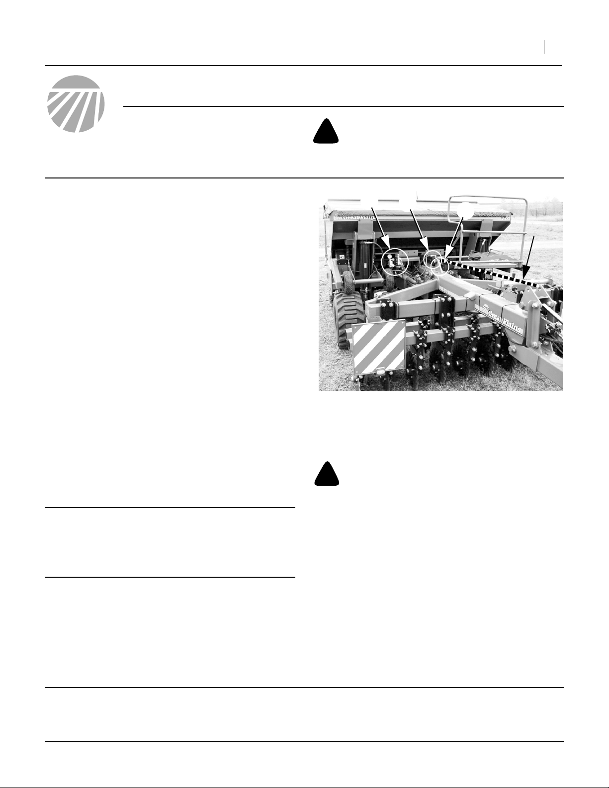
Refer to Figure 1
The kit replaces the level link arm ➀ (shown as a dotted
line in the figure) with a hydraulic cylinder ➁. The cylinder is controlled by a new valve assembly ➂ and
requires a new attachment point (lug) weldment ➃.
These instructions apply to:
148-765A Kit for Closed-Center Tractors
148-766A Kit for Open-Center Tractors
Due to shipping regulations, the kit does not include any
touch-up paint to restore the areas to be welded. Your
Great Plains dealer can provide it as Great Plains part:
821-001C PAINT GP GREEN SPRAY CAN
If this part is not available in your locale, use a green
exterior enamel paint close to Pantone 356.
When you see this symbol, the subsequent instructions
and warnings are serious - follow without exception.
!
Your life and the lives of others depend on it!
➂
➁
Figure 1
Upgrade Overview
➃
➀
25165
Before You Start
Each kit converts an entire drill. Inventory the contents
per the “Kit Parts List” on page 24.
IMPORTANT !
Make sure you have the correct kit for your tractor’s hydraulic system. If you have the incorrect
kit, it will not operate properly and can result in
equipment damage.
If necessary, move the implement to a well-lighted location suitable for disassembly. Make sure the ground/floor
under the tractor is non-flammable.
Note: Many of the hydraulic components are shipped
with protective caps. Leave these caps in place
until connections are made, to protect threads and
keep contaminants out of the hydraulic system.
©Copyright 2006 Printed 11/08/2006 148-771M
!
CAUTION
There will be sparks from welding. Dry grass, wood floor, or
areas with flammable fluid spills are not suitable locations for
installing this upgrade.
Lower the drill.
Park and secure the tractor, but leave it connected.
“Left” and “Right” are facing in the direction of machine
travel.
Have the following tools at hand:
• Wire or stick welder and welding tarps.
• Basic hand tools, including either adjustable openend wrenches or a set of fractional inch sizes.
• Paste or liquid tetrafluorethylene (Teflon®) pipe sealant (do not use pipe tape).
• Fluid collection pan.
Page 2
2 Opener Down Pressure Kit
Installation
Remove Level Link Arm
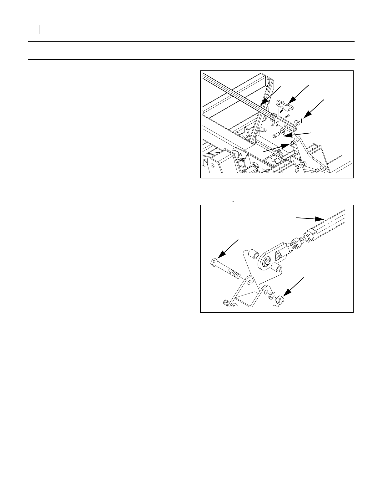
Refer to Figure 2
1. With the drill lowered, the link level arm ➀ is in nei-
ther tension nor compression. Open the float lock
lug ➁.
➄
➀
Great Plains Mfg., Inc.
➁
➂
➃
Refer to Figure 3
2. At the forward end of the level link ➀, remove bolt
➁ and nut ➂. This bolt and nut, and the washers,
are not re-used.
Refer to Figure 2
3. At the rear end of the link level arm, remove cotter
pin ➂ and clevis pin ➃. The pins (and the washers) are not re-used.
Note: There is a bushing ➄ in the rocker arm. Do not
remove it.
4. Remove the level link ➀ arm from the drill. It is not
re-used.
Figure 2
Relax Level Link
➁
Figure 3
Remove Level Link
25166
➀
➂
25167
148-771M 11/08/2006
Page 3
Great Plains Mfg., Inc.
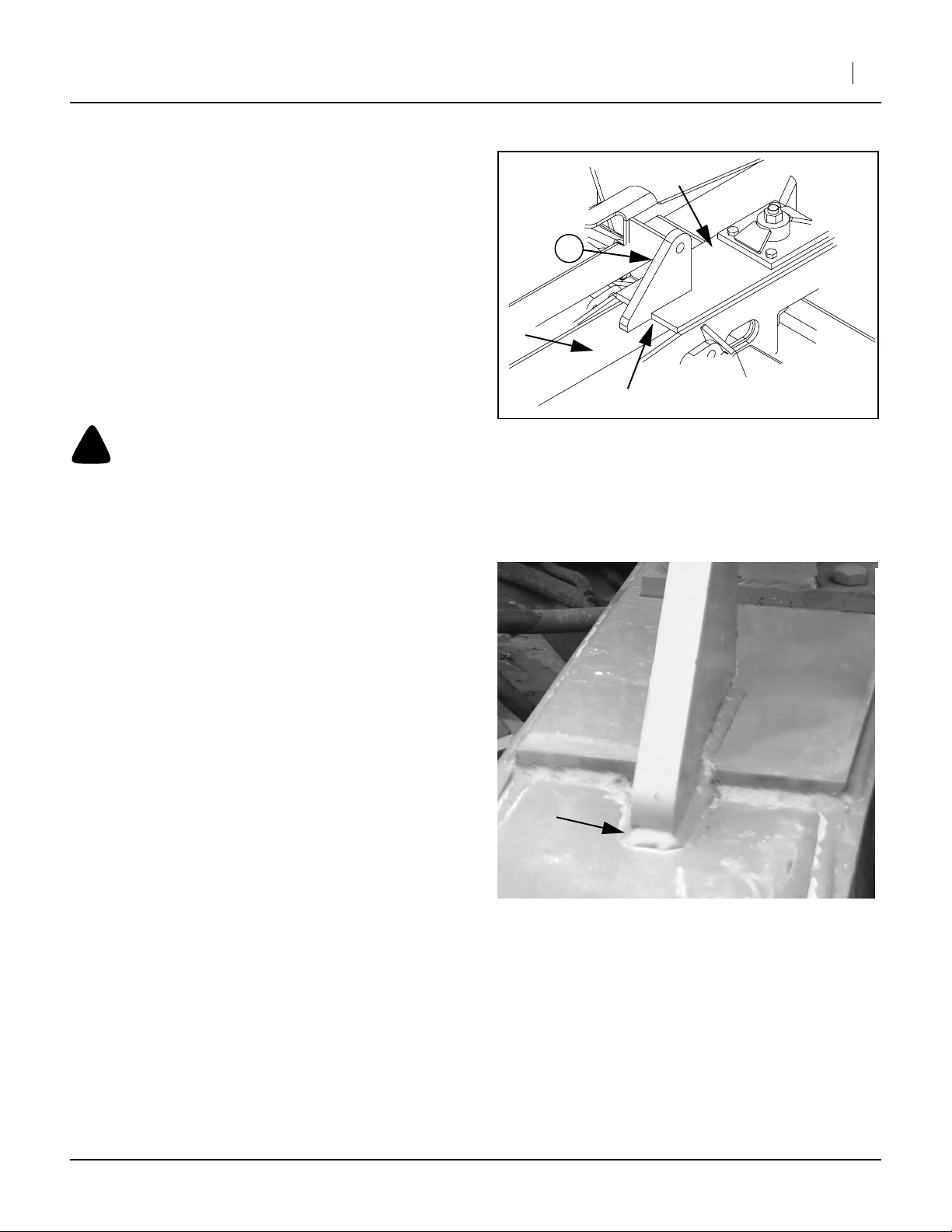
Weld Lug
Refer to Figure 4
5. Select lug (25) 248-508D,
(TOP LINK CYL LUG).
6. Temporarily position the new top link cylinder lug
(25) against the pivot plate ➀ on the drill frame ➁.
7. Center the lug (25) left-to-right, and push it as far
back against the pivot plate ➀ as possible before it
begins to ride up on the existing weld fillet. This
may leave a vertical gap at ➂.
8. Scribe the outline of the lug (25) on the pivot plate
➀.
9. Brush or sand the paint from the inscribed area,
plus ~1.3cm outside that area.
Installation Instructions 3
➀
25
➁
➂
!
CAUTION
Use caution when using tools that emit sparks such as welders. Wear suitable protective equipment. Do not use sparkemitting tools in areas where flammable or explosive materials may be present. Do not allow anyone to enter the path of
sparks.
Refer to Figure 4
10. Protect any nearby hoses or cables with welding
tarps.
11. Re-position the lug (25) as in step 7. Tack-weld the
lug in two places. Re-check centering and 90
degree vertical alignment.
12. Make a high tensile strength 100% wire or stick
weld around the entire base of the lug, with a fillet
of approximately 1.3cm.
13. Allow lug to cool.
14. Brush or sand off any burrs or other weld artifacts,
and paint. Apply a metal primer if a matching green
exterior enamel paint is not immediately available.
Figure 4
Position Lug
25168
Figure 5
Weld Lug
25169
Drain Hydraulic System
This upgrade kit is inserted in the existing hydraulic system at two points. Removing the fittings at these two
points will result in some loss of fluid (which is why it is
important to perform this and later steps after the welding). The following steps minimize fluid loss.
15. Put the tractor hydraulic controls into “float” mode.
16. Shutdown the tractor hydraulic system.
11/08/2006 148-771M
17. Loosen the fitting at the top of the left lift cylinder,
enough to let air enter at that point.
18. Set a collection pan under the right lift cylinder.
19. Loosen the fitting there enough to begin draining
fluid into the pan.
Page 4
4 Opener Down Pressure Kit
Assemble Closed-Center Valves
This section is for the 148-765A Closed-Center (CC) kit.
If you have the 148-766A Open-Center kit, see page 7.
Callout numbers are assigned from the “Kit Parts List”
on page 24.
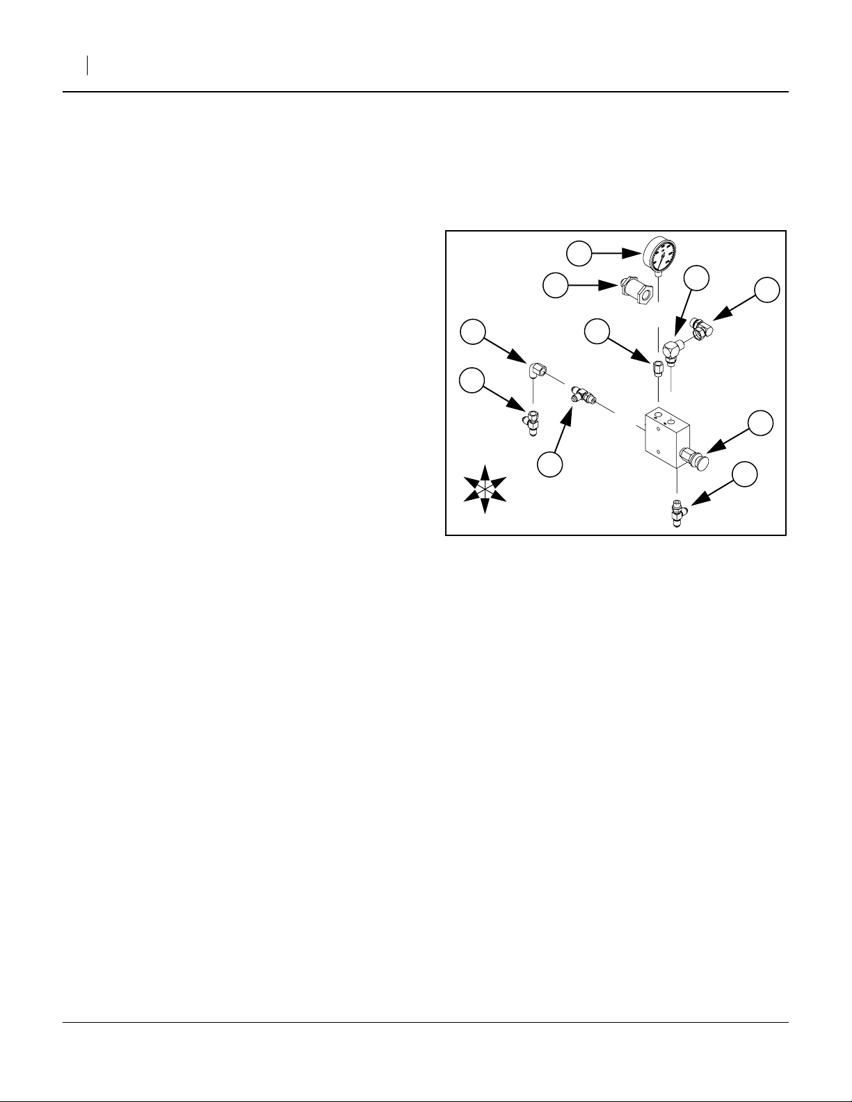
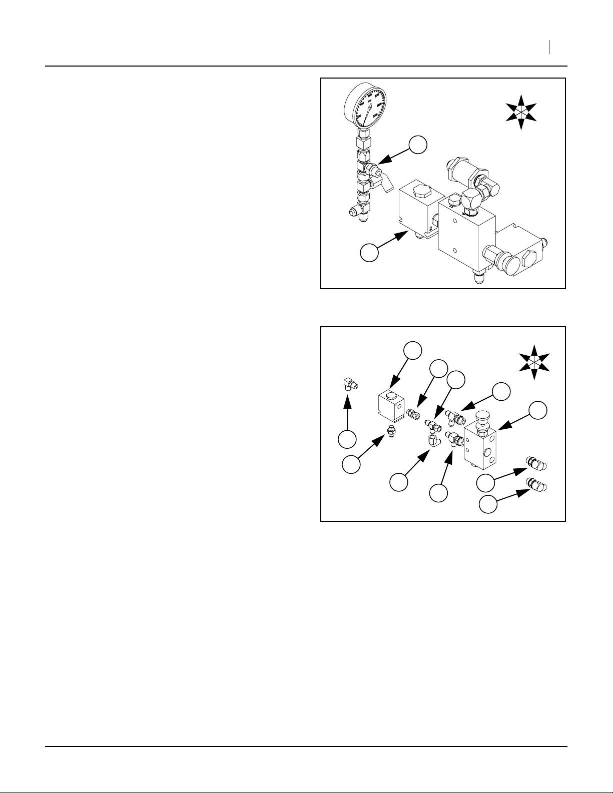
Assemble CC Down Pressure Control Valve
Refer to Figure 6
20. Select the (44) 810-301C,
(VALVE PRESS REDUCING W/CHECK).
Note: The orientation of the valve is that the control
knob faces Front and is toward the Bottom of the
valve body.
21. Select a (58) 811-216C,
(EL 3/4MJIC 9/16MORB).
Screw the male O-ring boss end into the Top Front
port of valve body (44). Adjust the JIC end to face
Left and tighten jam nut.
22. Select the (65) 811-677C,
(AD 9/16MORB 1/4FNPT).
Screw the male O-ring boss end into the Top Rear
port of valve body (44). Do not fully tighten.
23. Select a (52) 811-064C,
(TE 9/16MJIC 9/16MJIC 9/16MORB).
Screw the male O-ring boss end into the Rear port
of valve body (44). Adjust the tee so the center port
faces Right and tighten jam nut.
24. Select a (66) 841-077C,
(EL 3/4FJIC 3/4MORB).
Screw the female JIC end onto fitting (58). Adjust
angle so that the ell points to the Rear, and tighten.
25. Select the (43) 810-300C,
(PRESSURE GAUGE 3000 PSI).
Apply TFE sealant to threads. Screw it into fitting
(65). Tighten gauge to come as close as possible
to suggested torque values, and still have gauge
facing Forward.
26. Select a (52) 811-064C,
(TE 9/16MJIC 9/16MJIC 9/16MORB).
Screw the male O-ring boss end into the Bottom
port of valve body (44). Adjust the tee so the center
port faces Left and tighten jam nut.
27. Select a (52) 811-064C,
(TE 9/16MJIC 9/16MJIC 9/16MORB).
Screw the female JIC end onto fitting (52) on the
Rear of valve body (44). Make the final turns to
leave the open end facing down.
28. Select the (49) 810-554C,
(FILTER INLINE 3/4FORB 3/4MJIC).
Screw it onto fitting (66) and tighten.
Great Plains Mfg., Inc.
Torque fittings and fasteners per “Torque Values” on
page 23.
A cluster of arrows in each diagram shows directions (T)
Top, (B) Bottom, (L) Left, (R) Right, (F) Front and (R)
Rear.
43
58
66
55
49
65
50
44
T
R
R
52
L
52
F
B
Figure 6
CC Down Pressure Valve
25170
148-771M 11/08/2006
Page 5
Great Plains Mfg., Inc.
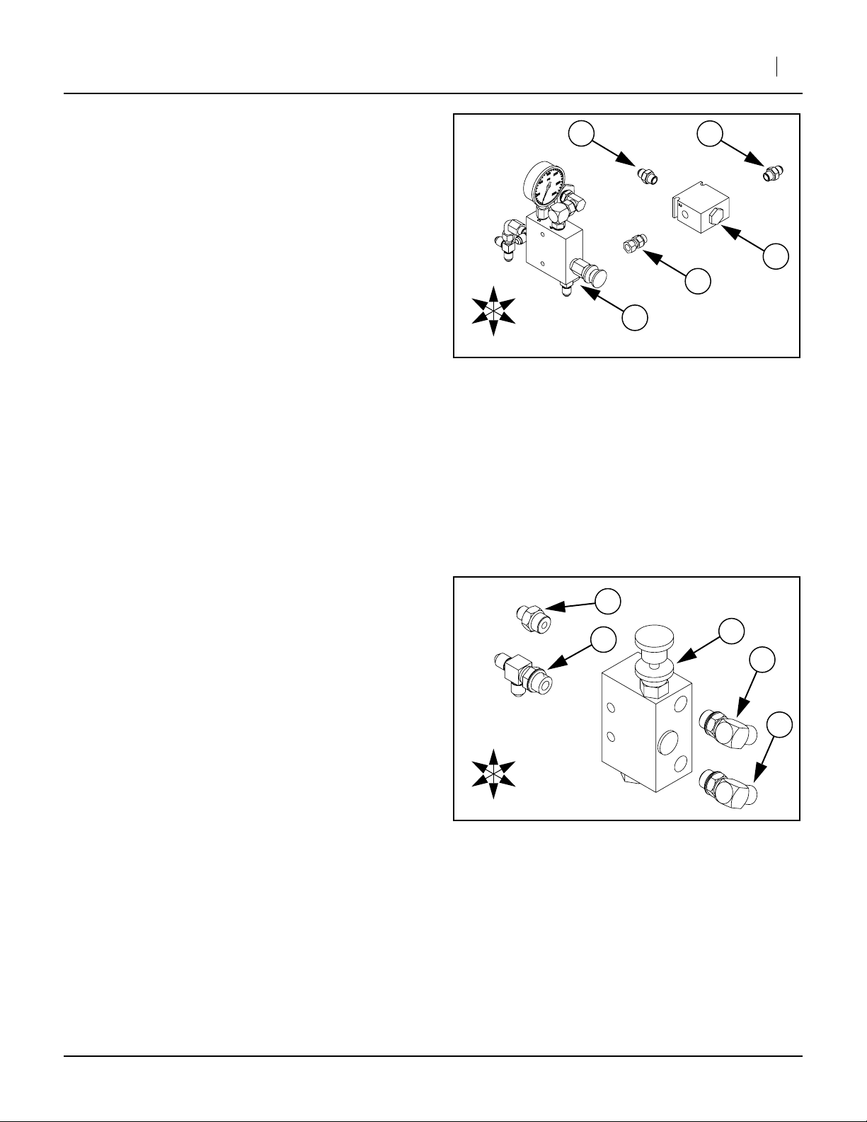
Assemble CC Check Valve
Refer to Figure 7
29. Select the (47) 810-428C,
(VALVE PO CHECK 4:1 W/9/16FORB).
Note: The ports of valve (47) are stamped with num-
bers “1”, “2” and “3”. Orient the valve so that Port
➀ is to the Left, port ➁ to the Right and port ➂ to
the Rear.
30. Select a (56) 811-170C,
(AD 9/16MORB 9/16MJIC).
Screw the male O-ring boss end into port ➀ of
valve body (44).
31. Select a (56) 811-170C,
(AD 9/16MORB 9/16MJIC).
Screw the male O-ring boss end into port ➂ of
valve body (44).
32. Select a (62) 811-627C,
(AD 9/16MORB 9/16FJIC).
Screw the male O-ring boss end onto check valve
assembly (47) at port ➁. Tighten jam nut.
R
R
T
B
Installation Instructions 5
56
➂
56
➀
➁
47
L
44
F
Figure 7
CC Check Valve
62
25171
33. Screw the check valve assembly (47), onto the
male JIC fitting at the Bottom of adjustment valve
assembly (44). Rotate check valve assembly (47)
so that port ➂ faces Rear before tightening JIC
nut.
Assemble CC Bypass Valve
Refer to Figure 8
34. Select the (48) 810-432C,
(HYDRAULIC BYPASS VALVE).
Note: Orient the valve (48) so that the adjustment knob
is on Top, toward Right and Front.
35. Select two (51) 811-063C,
(EL 3/4MJIC 3/4MORB).
Screw both into the Front ports of valve (48).
Rotate each to point to the Left and down before
tightening jam nuts.
36. Select a (59) 811-249C,
(TE 9/16MJIC 3/4MORB 9/16MJIC).
Screw the male O-ring boss end into the Rear Bottom port of valve (48). Point the center port of the
tee down before tightening jam nut.
37. Select a (54) 811-133C,
(AD 9/16MJIC 3/4MORB).
Screw the male O-ring boss end into the Rear Top
port of valve (48).
R
R
T
B
54
59
48
51
51
L
F
Figure 8
CC Bypass Valve
25172
11/08/2006 148-771M
Page 6
6 Opener Down Pressure Kit
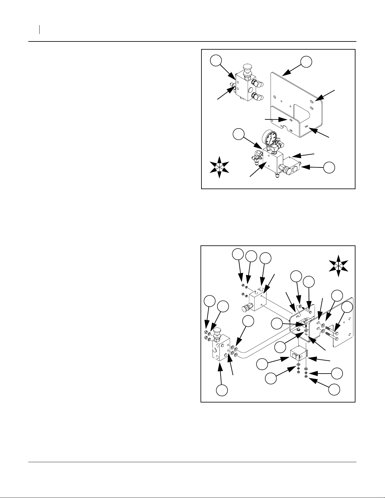
Assemble CC Valves on Mount
Refer to Figure 9 & Figure 10. Figure 10 shown exploded for clarity.
38. Select the (23) 248-506D,
(OPNR DOWN PRESSURE VALVE MNT).
Orient it so that the smaller of the two vertical
plates is to the Right, and the horizontal base plate
is at the Bottom.
Note: Both valve assemblies mount on the Right side of
the vertical plates. The check valve mounts under
the base.
39. Align the mounting holes ➀ of the adjustment
valve assembly (44) with the holes in the small vertical plate ➁. Align the notches ➂ in the check
valve assembly (47) with the holes under the base
plate ➃. This two valve assembly mounts outside
and under the mount.
40. Select two each:
(31) 802-551C, HHCS 1/4-20X2 1/4 GR5,
(39) 804-075C, WASHER FLAT 1/4 USS PLT,
(36) 804-006C, WASHER LOCK SPRING 1/4 PLT,
(32) 803-006C, NUT HEX 1/4-20 PLT.
From inside the mount, place a washer (39) on
each bolt (31) and insert the bolt out through plate
holes ➁, into the holes ➀ in the adjustment valve
(44) and loosely fit a lock washer (36) and nut (32).
R
R
48
➄
➁
44
T
L
F
B
➀
Figure 9
Mount Closed Center Valves
Great Plains Mfg., Inc.
23
➅
➃
➂
47
25173
41. Select two each:
(31) 802-551C, HHCS 1/4-20X2 1/4 GR5,
(36) 804-006C, WASHER LOCK SPRING 1/4 PLT,
(32) 803-006C, NUT HEX 1/4-20 PLT.
and four each:
(39) 804-075C, WASHER FLAT 1/4 USS PLT,
From inside the mount, place a washer (39) on
each bolt (31), down through the plate hole ➃ into
the notches ➂ of the check valve (47) and loosely
fit another washer (39), lock washer (36) and nut
(32).
42. Snug the valve assemblies (44)(47) against the
mounting plate (23), seat bolts deeply in notches,
and tighten all bolts and nuts.
43. Select two each:
(28) 802-024C, HHCS 3/8-16X3 GR5,
(37) 804-013C, WASHER LOCK SPRING 3/8 PLT
(33) 803-014C, NUT HEX 3/8-16 PLT
Select also six:
(40) 804-087C, WASHER FLAT 3/8 HARD
ASTMF436
From the Left outside of the mount, insert each bolt
(28) through one washer (40), then through the
plate holes ➅. Slide on two additional washers (40)
as spacers, then the bypass valve assembly (48)
via holes ➄. Fasten with a lock washer (37) and a
nut (33).
33
37
48
32
36
44
➀
➁
40
➄
Closed Center Fasteners
31
39
47
39
Figure 10
39
31
R
F
➅
T
R
L
B
40
28
➃
➂
36
32
25174
148-771M 11/08/2006
Page 7
Great Plains Mfg., Inc.
Installation Instructions 7
Assemble Open-Center Valve
This section is for the 148-766A Open-Center (OC) kit. If
you have the 148-765A Closed-Center kit, see page 4.
Callout numbers are assigned from the “Kit Parts List”
on page 24.
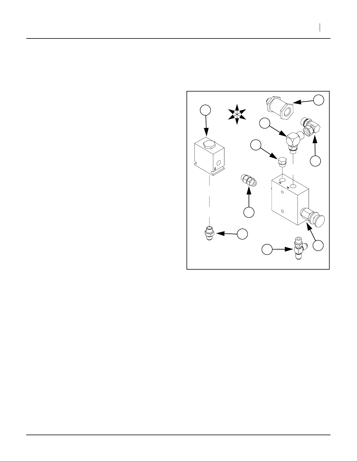
Assemble OC Down Pressure Control Valve and Shuttle Valve
Refer to Figure 6
44. Select the (44) 810-301C,
(VALVE PRESS REDUCING W/CHECK).
Orient it so that the control knob is on the Front,
toward the Bottom.
45. Select a (58) 811-216C,
(EL 3/4MJIC 9/16MORB).
Screw the male O-ring boss end into the Top Front
port of valve body (44). Adjust the JIC end to face
Left and tighten jam nut.
46. Select a (64) 811-675C,
(PL 9/16MORB HEX HEAD).
Screw the plug into the Top Rear port of valve body
(44) and tighten.
47. Select a (63) 811-636C,
(AD 9/16MORB STRAIGHT UNION).
Screw the male O-ring boss end into the Rear port
of valve body (44) Do not fully tighten at this time.
48. Select a (52) 811-064C,
(TE 9/16MJIC 9/16MJIC 9/16MORB).
Screw the male O-ring boss end into the Bottom
port of valve body (44). Adjust the tee so the center
port faces Left and tighten jam nut.
49. Select a (66) 841-077C,
(EL 3/4FJIC 3/4MORB).
Screw the female JIC end onto fitting (58). Adjust
angle so that the ell points to the Rear, and tighten.
50. Select the (49) 810-554C,
(FILTER INLINE 3/4FORB 3/4MJIC).
Screw it onto fitting (66) and tighten.
51. Select the (45) 810-343C,
(VALVE PO CHECK 2:1 W/9/16FORB).
Note: The ports of valve (45) are stamped with num-
bers “1”, “2” and “3”. Orient the check valve so
that port ➁ is to the Front, port ➀ to the Rear and
port ➂ at the Bottom.
Torque fittings and fasteners per “Torque Values” on
page 23.
A cluster of arrows in each diagram shows directions (T)
Top, (B) Bottom, (L) Left, (R) Right, (F) Front and (R)
Rear.
45
R
R
T
L
F
58
49
B
➀
64
➁
66
➂
63
56
52
Figure 11
OC Down Pressure Valve
44
25175
52. Select a (56) 811-170C,
(AD 9/16MORB 9/16MJIC).
Screw the O-ring boss end into port ➂ on the Bottom of check valve (45), and tighten.
53. Orient check valve (45) so that the hex nut is on
Top. Lay the Right faces of entire assembly on a
flat surface, and tighten union (63).
11/08/2006 148-771M
Page 8
8 Opener Down Pressure Kit
Assemble OC Check Valve Group
Great Plains Mfg., Inc.
54. Select a (47) 810-428C,
(VALVE PO CHECK 4:1 W/9/16FORB).
Note: The ports of check valve (47) are stamped with
numbers “1”, “2” and “3”. Orient the valve so that
Por t ➀ is to the Left, port ➁ to the Right and port
➂ to the Rear.
55. Select a (56) 811-170C,
(AD 9/16MORB 9/16MJIC).
Screw the male O-ring boss end into port ➀ of
valve body (47).
56. Select a (56) 811-170C,
(AD 9/16MORB 9/16MJIC).
Screw the male O-ring boss end into port ➂ of
valve body (47).
57. Select a (62) 811-627C,
(AD 9/16MORB 9/16FJIC).
Screw the male O-ring boss end onto check valve
assembly (47) at port ➁. Tighten jam nut.
58. Screw the check valve assembly (47), onto the
male JIC fitting at the Bottom of adjustment valve
assembly (44). Rotate check valve assembly (47)
so that port ➂ faces Rear before tightening JIC nut.
Assemble the OC Gauge Tree
Refer to Figure 13
59. Select a (60) 811-439C,
(TE 9/16MORB 9/16MJIC 9/16MJIC).
Orient the tee end ports up and down. The O-ring
boss port will face Front in final assembly.
60. Select a (61) 811-582C,
(AD 9/16FJIC 1/4FNPT).
Screw JIC end onto the Top of fitting (60). Tighten.
61. Select a (50) 811-061C,
(TE 9/16MJIC 9/16MJIC 9/16FJIC).
Screw female JIC end onto the Bottom of fitting
(60). Orient the side port to point Left, and tighten.
62. Select a (55) 811-169C,
(EL 9/16MJIC 9/16FJIC).
Screw it onto the center port off tee fitting (50). Orient the male end to point down and slightly forward, and tighten.
63. Select a (50) 811-061C,
(TE 9/16MJIC 9/16MJIC 9/16FJIC).
Screw female JIC end onto the Bottom of fitting
(50). Orient the side port to point Right. Tighten.
64. Select a (43) 810-300C,
(PRESSURE GAUGE 3000 PSI).
Apply pipe compound and screw into fitting (61).
Tighten so that the gauge faces Front.
44
50
50
56
Figure 12
OC Check Valve
43
Figure 13
OC Gauge Tree
➂
➁
61
60
47
62
55
➀
R
R
R
R
56
T
L
F
B
25176
T
L
F
B
25177
148-771M 11/08/2006
Page 9
Great Plains Mfg., Inc.
Installation Instructions 9
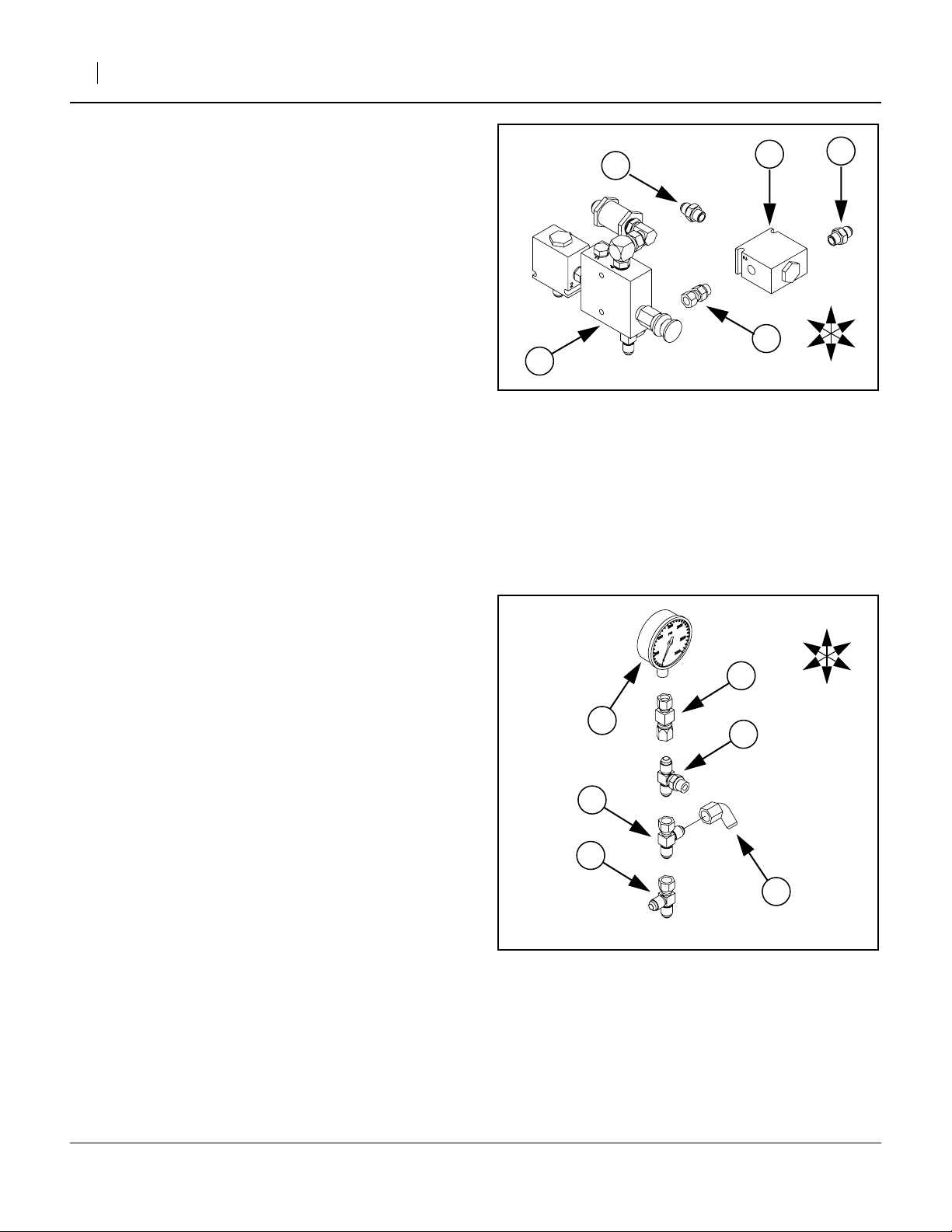
Connect Gauge Tree to Valve Assembly
Refer to Figure 14
65. Screw the center port of tee (60) onto the Rear
port ➀ of adjustment valve (45).
66. Orient gauge tree so that gauge is on Top.Tighten
the connection between tee (60) and check valve
(45) port ➀.
Assemble OC Bypass Valve Group
Refer to Figure 15
67. Select a (48) 810-432C,
(HYDRAULIC BYPASS VALVE).
Note: Orient the valve (48) so that the adjustment knob
is on Top, toward Right and Front.
68. Select two (51) 811-063C,
(EL 3/4MJIC 3/4MORB).
Screw both into the Front ports of valve (48).
Rotate each to point to the Left and down before
tightening jam nuts.
69. Select a (59) 811-249C,
(TE 9/16MJIC 3/4MORB 9/16MJIC).
Screw the male O-ring boss end into the Rear Bottom port of valve (48). Point the center port of the
tee down before tightening jam nut.
70. Select a (59) 811-249C,
(TE 9/16MJIC 3/4MORB 9/16MJIC).
Screw the male O-ring boss end into the Rear Top
port of valve (48). Point the center port of the tee
Right and down before tightening jam nut.
71. Select a (50) 811-061C,
(TE 9/16MORB 9/16MJIC 9/16MJIC).
Screw the male O-ring boss end into the Rear Top
port of the Bottom tee (59).
72. Select a (55) 811-169C,
(EL 9/16MJIC 9/16FJIC).
Screw female JIC end into the center (Bottom) port
of tee (50)
73. Select the (46) 810-344C,
(VALVE SHUTTLE 9/16FORB PORTS).
Note: The ports of valve (46) are stamped with numbers
“1”, “2” and “3”. Orient the shuttle valve so that port
➀ is to the Front, port ➁ to the Rear and port ➂ at
the Bottom.
74. Select a (53) 811-065C,
(EL 9/16MJIC 9/16MORB).
Screw the male ORB end into the Rear port ➁ of
shuttle valve (46). Orient the JIC end to point down.
75. Select a (56) 811-170C,
(AD 9/16MORB 9/16MJIC).
Screw the male ORB end into the Bottom port ➂ of
shuttle valve (46) and tighten.
T
R
R
B
60
➀
45
➁
53
➂
Figure 14
OC Gauge Tree to Valves
46
62
50
➀
59
25178
T
R
R
B
48
➂
56
55
59
Figure 15
OC Bypass Valve Group
76. Select a (62) 811-627C,
(AD 9/16MORB 9/16FJIC).
Screw the male ORB end into Front port ➀ of shuttle valve (46) and tighten.
77. Mate the shuttle valve (46) group to the bypass
valve (48) group at fittings (62) and (50). Tighten, so
that valve (46) port ➂ is down, and both valves align
when their Left sides are on a flat surface.
51
51
25179
L
F
L
F
11/08/2006 148-771M
Page 10

10 Opener Down Pressure Kit
Assemble OC Valves on Mount
Refer to Figure 16
78. Select the (23) 248-506D,
(OPNR DOWN PRESSURE VALVE MNT).
Orient it so that the smaller of the two vertical
plates is to the Right, and the horizontal base plate
is at the Bottom.
Note: Both valve assemblies mount on the Right side of
the vertical plates. The check valve mounts under
the base.
79. Position the adjustment valve assembly (44) so
that:
• The mounting holes (44) of the adjustment valve
align with the holes ➀ in the small vertical plate.
• The notches (45) in the shuttle valve align with
the holes ➁ with the holes in the small vertical
plate.
• The notches (47) in the check valve align with
the holes ➂ in the mount base.
46
➄
➁
Great Plains Mfg., Inc.
➃
➀
➂
47
R
48
23
T
L
45
44
Figure 16
Mount Open Center Valves
R
F
B
25180
148-771M 11/08/2006
Page 11

Great Plains Mfg., Inc.
Installation Instructions 11
Refer to Figure 17, shown exploded for clarity.
80. Select two each:
(31) 802-551C, HHCS 1/4-20X2 1/4 GR5,
(39) 804-075C, WASHER FLAT 1/4 USS PLT,
(36) 804-006C, WASHER LOCK SPRING 1/4 PLT,
(32) 803-006C, NUT HEX 1/4-20 PLT.
Insert the bolt (31) through the valve (44), and then
the mount (23) plate holes ➀. Loosely fit a flat
washer (39), lock washer (36) and nut (32).
81. Select two each:
(31) 802-551C, HHCS 1/4-20X2 1/4 GR5,
(39) 804-075C, WASHER FLAT 1/4 USS PLT,
(36) 804-006C, WASHER LOCK SPRING 1/4 PLT,
(32) 803-006C, NUT HEX 1/4-20 PLT.
Insert the bolt out through the mount (23) holes ➁,
into the shuttle valve notches (45). Loosely fit a flat
washer (39), lock washer (36) and nut (32).
82. Select two each:
(31) 802-551C, HHCS 1/4-20X2 1/4 GR5,
(36) 804-006C, WASHER LOCK SPRING 1/4 PLT,
(32) 803-006C, NUT HEX 1/4-20 PLT,
and four each:
(39) 804-075C, WASHER FLAT 1/4 USS PLT,
From inside the mount (23), place a washer (39) on
each bolt (31), down through the plate hole ➂ into
the check valve notches (47). Loosely fit another
flat washer (39), lock washer (36) and nut (32).
83. Snug the valve assembly (44)(45)(47) against the
mounting plate (23), seat all bolts deeply in
notches, and tighten all bolts and nuts.
Refer to Figure 18
84. Select two each:
(28) 802-024C, HHCS 3/8-16X3 GR5,
(37) 804-013C, WASHER LOCK SPRING 3/8 PLT
(33) 803-014C, NUT HEX 3/8-16 PLT
Select also six:
(40) 804-087C, WASHER FLAT 3/8 HARD
ASTMF436
From the Left outside of the mount, insert each bolt
(28) through one washer (40), then through the
plate holes ➃. Slide two additional washers (40) as
spacers, then the bypass valve assembly (48).
Fasten with a lock washer (37) and a nut (33).
85. Select two each:
(31) 802-551C, HHCS 1/4-20X2 1/4 GR5,
(39) 804-075C, WASHER FLAT 1/4 USS PLT,
(36) 804-006C, WASHER LOCK SPRING 1/4 PLT,
(32) 803-006C, NUT HEX 1/4-20 PLT.
From outside the mount, insert each bolt (31), then
through the plate hole ➄ into the notches of the
shuttle valve (46) and loosely fit a flat washer (39),
lock washer (36) and nut (32).
86. Snug the valve assembly (48)(46) against the
mounting plate (23), seat all bolts deeply in notches,
and tighten all bolts and nuts.
31
33
37
32
36
45
39
36
39
➀
44
31
39
47
36
Figure 17
Open Center Fasteners (R)
23
32
36
39
45
40
T
R
48
Open Center Fasteners (L)
F
Figure 18
L
B
R
32
➃
R
F
➂
40
T
R
L
B
31
➁
23
39
32
25181
➄
31
28
25182
11/08/2006 148-771M
Page 12

12 Opener Down Pressure Kit
Install Cylinder
The (42) 810-162C cylinder is supplied with 1in pins
and cotter pins in the base end. There may also be a pin
in the rod end. There may also be one or two washers
on each pin. These parts are not called out separately.
87. Select the (42) 810-162C,
(CYL 3.5X8X1.25 ROD (TIE ROD)).
Leave the protective caps in the ports.
88. If present, remove the pre-installed pin from the
rod end of the cylinder (42). This pin, cotter pin and
any washer(s) are not re-used.
89. Remove the pre-installed pin ➀ from the base end
of the cylinder (42). Save all parts.
90. Mount the base end of cylinder (42) on the frame
lug (25) welded earlier. Re-insert the pin components removed in step 89 and secure the cotter
pin.
91. Select the (67) 890-005C,
(BUSHING CYL 1 1/4 X 1 X 1).
Insert it inside the existing bushing in the rocker
arm ➁.
42
57
➁
➀
25
Figure 19
Down Pressure Cylinder
Great Plains Mfg., Inc.
24
27
67
T
R
F
R
L
B
25183
92. Select the:
(24) 248-507D, CYLINDER PIN and
(27) 800-245C, SNAP RING EXT 1 5304
93. Remove the protective caps from the cylinder
ports. Extend and rotate the rod (42) until the clevis
holes align with the top hole in the rocker arm ➁.
94. Insert pin (24), attaching rod (42) to rocker arm ➁.
95. Insert snap ring (27) in between the right face of
the rocker arm and the right lug of the clevis of rod
(42). Fully seat the snap ring.
96. Select two (57) 811-171C,
(EL 3/4MORB 9/16MJIC) ells.
Install the O-ring boss ends in the cylinder ports.
Before tightening, adjust the base end fitting to
point Right and slightly toward the Rear (approximately aimed at the valve assembly location).
Adjust the rod end fitting to point Right and Front.
Refer to Figure 20
97. Select the (12) 148-768S,
(5.625 CYL DEPTH CHNL ASSY).
Place it over the cylinder (42) rod, and slide to the
Rear up against the clevis end.
98. Select the (30) 802-114C,
(HHCS 3/8-16X2 1/2 GR5) and
(35) 803-078C,
(NUT LOCK 3/8-16 NYLON INSERT).
Insert the bolt (30) in the depth channel (12) and
secure it with the lock nut (35).
30
Figure 20
Cylinder Channel
R
F
12
35
42
T
R
L
B
25184
148-771M 11/08/2006
Page 13

Great Plains Mfg., Inc.
Install Valve Assembly
Refer to Figure 21 (Closed Center valve assembly shown, but Open
Center mounting shown - both are similar.)
The valve mounting bracket (23) itself mounts, via two
holes, to the right side of the right weight hanger ➀.
99. Select the two (29) 802-082C,
(HHCS 1/2-13X1 3/4 GR5) bolts,
and insert them through the valve assembly
mounting plate (23).
Note: If you are installing the Closed Center kit, omit
next step. Resume with step 101.
100. Select the four (41) 804-113C,
(WASHER FLAT 1/2 USS HARD PLT).
Slide them over the bolts (29).
101. Move the entire valve mount assembly (23) Left, so
the bolts (29) pass through the holes in the weight
hanger ➀.
102. Select two each (38) 804-015C,
(WASHER LOCK SPRING 1/2 PLT) and
(34) 803-020C,
(NUT HEX 1/2-13 PLT),
and tighten them onto the bolts.
R
F
T
B
Installation Instructions 13
B
23
L
Figure 21
Mount Valve Assembly
41
➀
29
38
34
25135
11/08/2006 148-771M
Page 14

14 Opener Down Pressure Kit
Great Plains Mfg., Inc.
Attach Closed-Center Hoses
This page is for the 148-765A Closed-Center kit. If you
have the 148-766A Open-Center kit, skip to page 15.
Refer to Figure 22. Although the valve assembly is complete at this
step, this figure is shown in exploded view to clarify bottom and rear
connections.
103. A. Select a 43cm hose (18) 811-702C,
(HH3/8R2 017 9/16FJIC).
Attach one end to the bottom port of the tee on the
bottom of adjustment valve (44). Attach the other
end to the bottom (center) port of the tee at the
rear lower port of bypass valve (48).
104. B. Select the 1.1m hose (20) 811-922C,
(HH3/8R2 045 9/16FJIC).
Attach one end to the end/rear/bottom port of the
tee at the end of the fitting tree at the rear port of
adjustment valve (44). Attach the other end to the
fitting at the base end of the down pressure cylinder (42).
105. C. Select a 43cm hose (18) 811-702C,
(HH3/8R2 017 9/16FJIC).
Attach one end to the rear port (#3) of the check
valve (47) under the mounting bracket. Attach the
other end to the fitting at the rear (center) port of
the tee at the end of the fitting tree at the rear port
of adjustment valve (44).
106. D. Select the 56cm hose (21) 811-926C,
(HH3/8R2 022 9/16FJIC).
Attach one end to the left port (#1) of the check
valve (47) under the mounting bracket. Attach the
other end to the fitting at the rod end port of the
down pressure cylinder (42).
107. Not shown:
Disconnect the “to tractor”/raise hose ➀ at the top
(base end) of the left lift cylinder ➁.
E. Shown:
Connect the “to tractor”/raise hose ➀ to the fitting at
the front bottom port of bypass valve (48).
108. Select an ell (57) 811-171C,
(AD 9/16MORB 9/16MJIC).
Remove the existing ell at the top (base end) of the
left lift cylinder ➁. Replace it with ell (57).
109. F. Select the 2.7m hose (17) 811-699C,
(HH3/8R2 106 9/16FJIC).
Attach one end to the rear port of the tee at the rear
lower port of bypass valve (48). Attach the other end
to the fitting ➁,(57) at the top (base end) of the left
lift cylinder.
T
R
F
B
L
17
B
57
F
57
18
48
19
44
➃
H
22
J
C
20
➂
A
G
E
B
47
D
18
➀
Figure 22
Closed Center Hoses
110. Not shown:
Disconnect the “from tractor”/lower hose ➂ at the
bottom (rod end) of the right lift cylinder ➃.
G. Shown:
Connect the “from tractor”/lower hose ➂ to the fitting
at the front top port of bypass valve (48).
111. Select an ell (57) 811-171C,
(AD 9/16MORB 9/16MJIC).
Remove the existing ell at the bottom (rod end) of
the right lift cylinder ➃. Replace it with ell (57)
112. H. Select a 1.3m hose (19) 811-705C,
(HH3/8R2 050 9/16FJIC).
Attach one end to the right-facing center port of the
tee at the rear port of adjustment valve (44). Attach
the other end to the fitting ➃,(57) at the bottom (rod
end) of the right lift cylinder.
113. K. Select the 38cm hose (22) 841-136C,
(HH3/8R2 015 9/16FJIC 3/4FJIC).
Connect one end to the in-line filter on the adjustment valve assembly (44). Attach the other end to
the top rear port of the bypass valve (48).
➁
21
42
25128
148-771M 11/08/2006
Page 15

Great Plains Mfg., Inc.
Installation Instructions 15
Attach Open-Center Hoses
This page is for the 148-766A Open-Center kit. If you
have the 148-765A Closed-Center kit, use page 14.
Refer to Figure 23. Although the valve assembly is complete at this
step, this figure is shown in exploded view to clarify bottom and rear
connections.
114. A. Select a 43cm hose (18) 811-702C,
(HH3/8R2 017 9/16FJIC).
Attach one end to the bottom port of the tee on the
bottom of adjustment valve (44). Attach the other
end to the bottom (center) port of the tee at the
rear lower port of bypass valve (48).
115. B. Select a 43cm hose (18) 811-702C,
(HH3/8R2 017 9/16FJIC).
Attach one end to the fitting on the bottom port (#3)
of the shuttle valve (46) on the rear of the bypass
valve (48). Attach the other end to the center/bottom port of the tee on the rear upper port of bypass
valve (48).
116. C. Select a 43cm hose (18) 811-702C,
(HH3/8R2 017 9/16FJIC).
Attach one end to the ell on the rear port (#1) of
the shuttle valve (46) on the rear of the bypass
valve (48). Attach the other end to the fitting on the
bottom port (#3) of the shuttle valve (46) on the
rear of the adjustment valve (44).
117. D. Select the1.1m hose (20) 811-922C,
(HH3/8R2 045 9/16FJIC).
Attach one end to the bottom end fitting port of the
gauge tree (42). Attach the other end to the fitting
at the base end of the down pressure cylinder (42).
118. E. Select a 43cm hose (18) 811-702C,
(HH3/8R2 017 9/16FJIC).
Attach one end to the rear port (#3) of the check
valve (47) under the mounting bracket. Attach the
other end to the left-facing (center) port of the tee
in the middle of the gauge fitting tree (42).
119. F. Select the56cm hose (21) 811-926C,
(HH3/8R2 022 9/16FJIC).
Attach one end to the left port (#1) of the check
valve (47) under the mounting bracket. Attach the
other end to the fitting at the rod end port of the
down pressure cylinder (42).
120. Not shown:
Disconnect the “to tractor”/raise hose ➀ at the top
(base end) of the left lift cylinder ➁.
G. Shown:
Connect the “to tractor”/raise hose ➀ to the fitting at
the front bottom port of bypass valve (48).
121. Select an ell (57) 811-171C,
(AD 9/16MORB 9/16MJIC).
Remove the existing ell at the top (base end) of the
left lift cylinder ➁. Replace it with ell (57).
➃
48
➂
57
44
46
➀
J
46
G
19
K
42
22
C
B
A
18
D
20
Figure 23
Open Center Hoses
17
L
F
T
R
F
B
L
B
➁
57
H
E
18
47
21
42
25131
11/08/2006 148-771M
Page 16

16 Opener Down Pressure Kit
Great Plains Mfg., Inc.
Refer to Figure 24
122. H. Select the 2.7m hose (17) 811-699C,
(HH3/8R2 106 9/16FJIC).
Attach one end to the ell at the tee in the fitting tree
between bypass valve (48) and its shuttle valve
(46). Attach the other end to the fitting ➁,(57) at
the top (base end) of the left lift cylinder.
123. Not shown:
Disconnect the “from tractor”/lower hose ➂ at the
bottom (rod end) of the right lift cylinder ➃.
J. Shown:
Connect the “from tractor”/lower hose ➂ to the fitting at the front top port of bypass valve (48).
124. Select an ell (57) 811-171C,
(AD 9/16MORB 9/16MJIC).
Remove the existing ell at the bottom (rod end) of
the right lift cylinder ➃. Replace it with ell (57)
125. K. Select a 1.3m hose (19) 811-705C,
(HH3/8R2 050 9/16FJIC).
Attach one end to the right-facing (center) port of
the tee low in gauge fitting tree (42). Attach the
other end to the fitting ➃,(57) at the bottom (rod
end) of the right lift cylinder.
126. L. Select a 38cm hose (22) 841-136C,
(HH3/8R2 015 9/16FJIC 3/4FJIC).
Connect one end to the in-line filter on the adjustment valve assembly (44). Attach the other end to
the top rear port of the bypass valve (48).
➃
48
➂
57
44
46
J
46
G
18
A
K
B
19
42
T
R
F
B
L
B
17
57
➁
22
H
L
E
18
C
F
47
21
D
➀
20
Figure 24
Open Center Hoses
42
25131
148-771M 11/08/2006
Page 17

Great Plains Mfg., Inc.
Purge and Re-phase System
!
WARNING
Escaping fluid under pressure can have sufficient pressure to
penetrate the skin causing serious injury. Avoid the hazard by
relieving pressure before disconnecting hydraulic lines. Use a
piece of paper or cardboard, NOT BODY PARTS, to check for
leaks. Wear protective gloves and safety glasses or goggles
when working with hydraulic systems. If an accident occurs,
see a doctor immediately. Any fluid injected into the skin must
be surgically removed within a few hours or gangrene will
result.
Refer to Figure 25
127. Close the Bypass valve (48) (turn fully clockwise).
128. Close the Adjustment valve (44) (turn fully clockwise), and open (clockwise) on full turn.
129. Purge the hydraulic system of air per the instructions in the Operator’s Manual.
130. Re-phase the lift cylinders per the instructions in
the Operator’s Manual.
131. Inspect the system for leaks. Raise and lower drill
once or twice, and note where the new hoses rub
other implement components, or need to be protected from other moving parts.
Post-Installation Lift Cycle
The gauge wheel lift cylinders are on the same circuit
as the new pressure compensating system (although
the lift cylinders do not rely on the compensated pressure). Be aware of, and check, the new lift/lower
sequencing.
43
Installation Instructions 17
➁
Figure 25
Closed Center Valves
48
➀
44
25185
Raising:
a. Gauge wheels lift drill.
b. Opener sub-frame lifts openers.
Lowering:
a. Gauge wheels lower drill onto cylinder stops of
gauge wheel cylinders.
b. Opener sub-frame lowers opener to the ground
and pressure compensating valve pressurizes
openers to selected setting.
132. Select ties (26) 800-035C,
(CABLE TIE .31X28 8DIA 120LB).
Secure the new hoses as necessary to protect
them in field operations.
11/08/2006 148-771M
Page 18

18 Opener Down Pressure Kit
Calibrate Bypass Valve (CC only)
Refer to Figure 26
If your tractor has Open Center hydraulics, refer to
“Open Center Operation” on page 21. If you are
unsure what type of hydraulic system is on your tractor,
contact your tractor manufacturer.
Note: Refer to “Post-Installation Lift Cycle” on
page 17 to know what to expect the drill to do as
hydraulics are cycled.
Tractors with Pressure Compensating Closed Center Hydraulics (PC Closed)
133. Release locking disk ➀. Close bypass valve (48)
for no oil flow by turning knob on valve clockwise
completely. Tighten locking disk ➀. Always operate the drill with the bypass valve closed.
Tractors with Load Sensing Closed Center Hydraulics (LS Closed) or Pressure Flow Compensating
(PFC) Systems
43
➁
Figure 26
Closed Center Valves
Great Plains Mfg., Inc.
48
➀
44
25185
IMPORTANT !
Failure to use the bypass valve on load-sensing
tractors may cause major tractor damage.
134. Release locking disk ➀. Close bypass valve (48) for
no oil flow by turning knob on valve clockwise completely. Tighten locking disk ➀.
135. With tractor at half throttle, adjust flow-control valve
on tractor so openers raise and lower at a reasonable speed. Keep tractor at one-half throttle for
remaining steps.
Note: Faster opener raise/lower increases potential for
oil over-heating, excess wear and tractor damage.
136. Engage tractor hydraulics and lower openers. Lock
hydraulic lever on tractor for continuous operation.
137. Release locking disks ➀ and ➁. Adjust pressurecontrol valve (44) for opener down pressure so
gauge (43) is at 1800 psi.
138. While watching gauge (43), slowly turn knob on
bypass valve (48) counterclockwise. Adjust bypass
valve (48) just until needle on gauge (43) begins to
move down from 1800 psi. Use locking disk ➀ to
lock bypass valve at this setting. (See also note
below.)
139. Adjust pressure-control valve (44) to desired opener
down pressure per “Closed Center Field Opera-
tion” on page 19. Tighten locking disk ➁.
Note: The higher the bypass pressure, the greater the
potential for oil over-heating and tractor damage.
At the same time, for proper opener operation the
bypass valve must be set at least 300 psi above
the opener down-pressure setting when the tractor
is at one-half throttle. Therefore, you should set
the bypass valve as low as possible while staying
at least 300 psi above the opener down pressure
setting.
While 1800 psi is a good starting point for setting the
bypass valve, if you consistently operate the drill with low
opener down pressure you can set the bypass valve
below 1800 psi. If you consistently operate the drill with
very high opener down pressure, you may need a
bypass-valve setting above 1800 psi.
148-771M 11/08/2006
Page 19

Great Plains Mfg., Inc.
Operation
Installation Instructions 19
Closed Center Field Operation
The openers are mounted on floating opener frames
which follow the contour of the ground while maintaining
constant opener down pressure.
1. Lower the opener frames by pushing FORWARD on
the tractor remote hydraulic lever. The remote lever
must be LOCKED OPEN in this position to provide
constant pressure/flow to the openers.
John Deere tractors with Sound-Gard ® Body:
Use lever lock clip, John Deere part number
R52667, to lock lever forward. See your tractor
dealer for clip purchase and installation.
John Deere 7000 Series tractors: Rotate valve
detent selector to motor position to lock lever in forward position.
John Deere 8000 Series tractors: Set timer to continuous. Push lever forward until detent clicks.
Case-IH Magnum tractors: Lock lever forward in
detent position. You may need to turn up detent
pressure to its maximum setting. Do not tie hydraulic
lever past detent position with a strap. See your tractor dealer for hydraulic-system details.
Other tractors: Lock lever forward in detent position. You may need to turn up detent pressure to
maximum or use a mechanical detent holder to hold
lever forward. See your tractor dealer for proper
means of providing constant flow to openers.
Refer to Figure 27
43
2. With the tractor hydraulic lever locked forward,
release the lock disk ➀, turn the knob on the pressure control valve (44) as shown in Figure 27. Watch
the pressure gauge (43) and dial in the desired pressure on the openers. Clockwise increases the pressure and counterclockwise decreases pressure.
Once the pressure is set, lock the knob with the lock
disk ➀.
Note: Refer to “Post-Installation Lift Cycle” on page 17
to know what to expect the drill to do as hydraulics
are cycled.
The recommended pressure range for drilling is between
200 psi and 1400 psi. Setting the opener down pressure
above 1600 psi will raise the drive wheels off the ground
when the seed box is empty causing skips and poor seed
metering. See the following table for the relationship
between psi and down force.
The following down-forces are per-opener, with no extra
weight on the hangers (at the lower down-force values).
Higher down-force values may require weights on the
hangers. Consult the Operator’s Manual for further information.
Adjustment Valve Table
System
PSI
200 62 137
300 77 170
400 84 185
500 96 212
600 110 243
700 123 272
800 139 306
900 155 341
1000 173 380
1100 194 427
1200 217 479
1300 249 548
1400 268 591
Down Force
Pounds Kg
➀
Figure 27
Closed Center Valves
11/08/2006 148-771M
44
25185
Page 20

20 Opener Down Pressure Kit
Great Plains Mfg., Inc.
Refer to Figure 28
➁
➂
➀
Figure 28
Opener Adjustment
3. After the opener pressure is set, opener depth ➀ is
controlled by the press wheel adjustment. Attached
to the rear of each opener is one of several optional
press wheels. The press wheels close the furrow
and gently press soil over the seed while also providing depth control for the opener. To adjust the
position of the press wheel, which automatically
changes the seeding depth of the opener, lift the “T”
handle located on top of the opener and slide it for-
ward ➁ or rearward ➂ until the seeding depth is
correct, as shown in Figure 2-10. Moving the handle
forward ➁ plants shallower while moving the handle
rearward ➂ plants deeper. A spring loaded pin
holds the “T” handle at the setting to maintain the
proper depth. Lift the opener frames slightly to take
the pressure off the “T” handles when adjusting the
press wheel depth.
Note: The opener pressure setting controls the soil firm-
ing pressure on the press wheel as well as the disk
penetrating force. DO NOT use more opener down
pressure than necessary to obtain the desired
opener penetration and to maintain the proper
firming action over the seed. Set the planting
depth with the depth controlling press wheel and
only use enough opener pressure to cut the proper
seed groove and maintain the desired soil firming
action. Excessive opener force will lead to excessive wear and damage of the opener components.
15659
Priority Flow Hydraulic Systems
On some tractors with load-sensing hydraulics, the circuit
#1 is capable of taking nearly 100 percent of available
hydraulic flow. Operating the openers or markers on circuit #1 will starve the other circuit, making one function
inoperable.
To operate markers and constant opener down pressure
at the same time, connect the openers to circuit #2 and
the markers to circuit #3.
Note: On some tractors with very positive remote
hydraulic checks, a slight increase in the reading
on the pressure gauges may occur after the tractor
remote lever is returned to neutral. This is caused
by back pressure on the opener cylinders and
should be ignored. The NET OPERATING PRESSURE on the opener cylinders is maintained at the
pressure you selected while the tractor remote
lever was held forward–not at the “apparently
increased” pressure. Reactivating the tractor lever
forward will confirm this.
148-771M 11/08/2006
Page 21

Great Plains Mfg., Inc.
Installation Instructions 21
Open Center Operation
This section covers Non-Active Hydraulic Systems -Tractors with open-center hydraulic systems or fixed-displacement hydraulic pumps.
If your tractor has Closed Center hydraulics, refer to
“Closed Center Field Operation” on page 19. If you are
unsure what type of hydraulic system is on your tractor,
contact your tractor manufacturer.
Refer to Figure 29
43
48
➀
44
➁
Figure 29
Open Center Valves
Note: Refer to “Post-Installation Lift Cycle” on page 17
to know what to expect the drill to do as hydraulics
are cycled.
1. Release locking disk ➀. Close bypass valve (48) for
no oil flow by turning knob on valve clockwise completely. Always operate the drill with the bypass
valve closed. Lock disk ➀.
2. Lower the opener frames by pushing FORWARD on
the tractor remote hydraulic lever. The remote lever
must be TEMPORARILY LOCKED OPEN in this
position while the pressure adjustment is being
made to provide constant pressure and flow to the
openers.
John Deere tractors with Sound-Gard ® Body:
Use lever lock clip, John Deere part number
R52667, to lock lever forward. See your tractor
dealer for clip purchase and installation.
25186
John Deere 7000 Series tractors: Rotate valve
detent selector to motor position to lock lever in forward position.
John Deere 8000 Series tractors: Set timer to continuous. Push lever forward until detent clicks.
Case-IH Magnum tractors: Lock lever forward in
detent position. You may need to turn up detent
pressure to its maximum setting. Do not tie hydraulic
lever past detent position with a strap. See your tractor dealer for hydraulic-system details.
Other tractors: Lock lever forward in detent position. You may need to turn up detent pressure to
maximum or use a mechanical detent holder to hold
lever forward. See your tractor dealer for proper
means of providing constant flow to openers.
3. Release locking disk ➁. With the tractor hydraulic
lever locked forward, turn the knob on the pressure
control valve (44) as shown in Figure 29. Watch the
pressure gauge (43) and dial in the desired pressure
on the openers. Clockwise increases the pressure,
and counterclockwise decreases pressure. Once
the pressure is set, lock each knob with the lock disk
➁. The recommended pressure range for drilling is
between 200 psi and 1400 psi. Setting the opener
down pressure above 1600 psi. will raise the drive
wheels off the ground when the seed box is empty
causing skips and poor seed metering. See the following table for the relationship between psi and
down force..
Adjustment Valve Table
System
PSI
200 62 137
300 77 170
400 84 185
500 96 212
600 110 243
700 123 272
800 139 306
900 155 341
1000 173 380
1100 194 427
1200 217 479
1300 249 548
1400 268 591
As a general starting point, set hydraulic down pressure
to 800 psi. For most field conditions, adjust down pressure between 200 and 1400 psi. Setting the opener down
pressure above 1600 psi. will raise the drive wheels off
Down Force
Pounds Kg
11/08/2006 148-771M
Page 22

22 Opener Down Pressure Kit
Great Plains Mfg., Inc.
the ground when the seed box is empty causing skips
and poor seed metering. Refer to the chart on the previous page for approximate force at the openers for a given
pressure setting.
4. After the opener pressure is set, RETURN THE
TRACTOR REMOTE HYDRAULIC LEVER TO ITS
NEUTRAL POSITION. This “locks in” the previously
selected pressure and the opener frames remain in
a fixed position.
Note: On some tractors with very positive remote
hydraulic checks, a slight increase in the reading
on the pressure gauges may occur after the tractor
remote lever is returned to neutral. This is caused
by back pressure on the opener cylinders and
should be ignored. The NET OPERATING PRESSURE on the opener cylinders is maintained at the
pressure you selected while the tractor remote
lever was held forward–not at the “apparently
increased” pressure. Reactivating the tractor lever
forward will confirm this.
Each time the drill is lowered, hold the tractor remote
hydraulic lever forward for a few seconds to recharge the
circuit, then return it to its neutral position. The tractor
and drill should be on level ground when you return the
tractor lever to neutral.
The open center hydraulic kit allows the tractor operator
to momentarily operate the opener down pressure circuit
as an active circuit. When approaching a mound or valley
where active hydraulics is desirable, the tractor operator
can MOMENTARILY PUSH THE TRACTOR REMOTE
HYDRAULIC LEVER FORWARD which will allow the
opener frames to follow the uneven terrain with constant
opener down pressure. As soon as the drill returns to
level ground RETURN THE TRACTOR REMOTE
HYDRAULIC LEVER TO ITS NEUTRAL POSITION to
“lock in” the preset pressure once again. DO NOT activate the tractor remote hydraulic lever for more than 20
seconds at a time, once every 2 minutes. Always wait
until the tractor and drill are on level ground before
returning the tractor remote hydraulic lever to its neutral
position. The tractor remote hydraulic lever can be
momentarily bumped forward any time on level ground to
assure the preset pressure is correctly locked in and to
reset the system if it has not been operated for a long
period of time.
Note: The opener pressure setting controls the soil firm-
ing pressure on the press wheel as well as the disk
penetrating force. DO NOT use more opener down
pressure than necessary to obtain the desired
opener penetration and to maintain the proper
firming action over the seed. Set the planting
depth with the depth controlling press wheel and
only use enough opener pressure to cut the proper
seed groove and maintain the desired soil firming
action. Excessive opener force will lead to excessive wear and damage of the opener components.
Refer to Figure 30f
➁
➂
➀
Figure 30
Opener Adjustment
5. After the opener pressure is set, opener depth ➀ is
controlled by the press wheel adjustment. Attached
to the rear of each opener is one of several optional
press wheels. The press wheels close the furrow
and gently press soil over the seed while also providing depth control for the opener. To adjust the
position of the press wheel, which automatically
changes the seeding depth of the opener, lift the “T”
handle located on top of the opener and slide it for-
ward ➁ or rearward ➂ until the seeding depth is
correct, as shown in Figure 2-10. Moving the handle
forward ➁ plants shallower while moving the handle
rearward ➂ plants deeper. A spring loaded pin
holds the “T” handle at the setting to maintain the
proper depth. Lift the opener frames slightly to take
the pressure off the “T” handles when adjusting the
press wheel depth.
6. After opener down pressure is set, return tractor
hydraulic lever to neutral. This locks in the selected
pressure, and opener frames will remain fixed in this
position.
IMPORTANT !
Open-center tractors and tractors with fixed-displacement pumps are not designed to provide a
continuous supply of pressurized oil to remote
valves. Locking hydraulic lever forward on these
tractors can cause overheating of hydraulic oil
and tractor damage. After setting opener down
pressure, always return hydraulic lever to neutral.
15659
148-771M 11/08/2006
Page 23

Great Plains Mfg., Inc.
Maintenance
Installation Instructions 23
In-Line Hydraulic Filter
25187
If raising or lowering times slow noticeably, check the inline filter, and clean as necessary.
Installation Reference Information
Connector Identification
➁
➂
➇
➆
➅
➄
➀
➀ JIC - Joint Industry Conference (SAE J514)
Note straiight threads ➁ and the
37° cone ➂ on “M” fittings (or 37° flare on “F”).
➃ ORB - O-Ring Boss (SAE J514)
Note the straight threads ➄ and,
elastomer O-Ring ➅.
Fittings needing orientation, such as the ell above,
also have a washer ➆ and
jam nut ➇ (“adjustable thread port stud”)
➃
25188
To clean the filter:
1. Set tractor’s opener down-force hydraulic circuit to
float.
2. Shut down tractor.
3. Loosen connections at the in-line filter and allow a
few minutes for drain-back.
4. Disconnect and cap the hose to the filter.
5. Disassemble the filter in place.
6. Remove the 50 micron screen. Wash with solvent
and use compressed air to dislodge any debris.
Note: If the filter screen needs to be replaced, order an
810-553C from your Great Plains dealer.
7. Reassemble filter and reconnect hose.
8. Complete a hydraulic system purge and re-phase
per your Operator’s manual.
Torque Values
Fastener/Fitting Ft-Lbs N-m
1
⁄4 NPT
1
⁄4-20 GR5
3
⁄8-16 GR5
1
⁄2-13 GR5
9
⁄16 JIC
9
⁄16 ORB w/jam nut
9
⁄16 ORB straight
3
⁄4 JIC
3
⁄4 ORB w/jam nut
3
⁄4 ORB straight
1.5-3.0 turns past finger tight
811
31 42
76 105
18-20 24-27
12-16 16-22
18-24 24-32
27-39 37-53
20-30 27-41
27-43 37-58
- NPT - National Pipe Thread (not shown)
have tapered threads, no cone/flare, no O-ring.
11/08/2006 148-771M
Page 24

Great Plains Mfg., Inc.
24 Opener Down Pressure Kit
Kit Parts List
Opener Down Pressure Kits
The part call-out numbers in this list match all Figures in the installation instructions, but not the support parts lists
starting on page 26. Your kit includes:
Quantity per 401-
(Callout) Part No.
(11) 148-771M 1 1 This manual
(12) 148-768S 1 1 5.625 CYL DEPTH CHNL ASSY
(13) 113-357D 2 2 RUBBER CYL LOCK CHANNEL PAD
(14) 148-767H 1 1 5.625 CYL DEPTH CHNL WLMT
(15) 148-769V 1 0 VALVE ASSY- C.C. HOSE BUNDLE
(16) 148-770V 0 1 VALVE ASSY- O.C. HOSE BUNDLE
(17) 811-699C 1 1 HH3/8R2 106 9/16FJIC
(18) 811-702C 2 4 HH3/8R2 017 9/16FJIC
(19) 811-705C 1 1 HH3/8R2 050 9/16FJIC
(20) 811-922C 1 1 HH3/8R2 045 9/16FJIC
(21) 811-926C 1 1 HH3/8R2 022 9/16FJIC
(22) 841-136C 1 1 HH3/8R2 015 9/16FJIC 3/4FJIC
(23) 248-506D 1 1 OPNR DOWN PRESSURE VALVE MNT
(24) 248-507D 1 1 CYLINDER PIN
(25) 248-508D 1 1 TOP LINK CYL LUG
(26) 800-035C 6 6 CABLE TIE .31X28 8DIA 120LB
(27) 800-245C 1 1 SNAP RING EXT 1 5304
(28) 802-024C 2 2 HHCS 3/8-16X3 GR5
(29) 802-082C 2 2 HHCS 1/2-13X1 3/4 GR5
(30) 802-114C 1 1 HHCS 3/8-16X2 1/2 GR5
(31) 802-551C 4 8 HHCS 1/4-20X2 1/4 GR5
(32) 803-006C 4 8 NUT HEX 1/4-20 PLT
(33) 803-014C 2 2 NUT HEX 3/8-16 PLT
(34) 803-020C 2 2 NUT HEX 1/2-13 PLT
(35) 803-078C 1 1 NUT LOCK 3/8-16 NYLON INSERT
(36) 804-006C 4 8 WASHER LOCK SPRING 1/4 PLT
(37) 804-013C 2 2 WASHER LOCK SPRING 3/8 PLT
(38) 804-015C 2 2 WASHER LOCK SPRING 1/2 PLT
(39) 804-075C 6 10 WASHER FLAT 1/4 USS PLT
(40) 804-087C 6 6 WASHER FLAT 3/8 HARD ASTMF436
(41) 804-113C 4 4 WASHER FLAT 1/2 USS HARD PLT
(42) 810-162C 1 1 CYL 3.5X8X1.25 ROD (TIE ROD)
(43) 810-300C 1 1 PRESSURE GAUGE 3000 PSI
-765A -766A
Part Description
148-771M 11/08/2006
Page 25

Great Plains Mfg., Inc.
Quantity per 401-
(Callout) Part No.
(44) 810-301C 1 1 VALVE PRESS REDUCING W/CHECK
(45) 810-343C 0 1 VALVE PO CHECK 2:1 W/9/16FORB
(46) 810-344C 0 1 VALVE SHUTTLE 9/16FORB PORTS
(47) 810-428C 1 1 VALVE PO CHECK 4:1 W/9/16FORB
(48) 810-432C 1 1 HYDRAULIC BYPASS VALVE
(49) 810-554C 1 1 FILTER INLINE 3/4FORB 3/4MJIC
(50) 811-061C 1 3 TE 9/16MJIC 9/16MJIC 9/16FJIC
(51) 811-063C 2 2 EL 3/4MJIC 3/4MORB
(52) 811-064C 2 1 TE 9/16MJIC 9/16MJIC 9/16MORB
(53) 811-065C 0 1 EL 9/16MJIC 9/16MORB
(54) 811-133C 1 0 AD 9/16MJIC 3/4MORB
(55) 811-169C 1 2 EL 9/16MJIC 9/16FJIC
(56) 811-170C 2 4 AD 9/16MORB 9/16MJIC
(57) 811-171C 4 4 EL 3/4MORB 9/16MJIC
(58) 811-216C 1 1 EL 3/4MJIC 9/16MORB
(59) 811-249C 1 2 TE 9/16MJIC 3/4MORB 9/16MJIC
(60) 811-439C 1 1 TE 9/16MORB 9/16MJIC 9/16MJIC
(61) 811-582C 0 1 AD 9/16FJIC 1/4FNPT
(62) 811-627C 1 2 AD 9/16MORB 9/16FJIC
(63) 811-636C 0 1 AD 9/16MORB STRAIGHT UNION
(64) 811-675C 0 1 PL 9/16MORB HEX HEAD
(65) 811-677C 1 0 AD 9/16MORB 1/4FNPT
(66) 841-077C 1 1 EL 3/4FJIC 3/4MORB
(67) 890-005C 1 1 BUSHING CYL 1 1/4 X 1 X 1
-765A -766A
Part Description
Installation Instructions 25
11/08/2006 148-771M
Page 26

26 Opener Down Pressure Kit
Support Parts - V300 Drill, Closed-Center Down-Pressure
The part call-out numbers in this section do not match the merged list in the installation instructions.
Great Plains Mfg., Inc.
25128
148-771M 11/08/2006
Page 27

Great Plains Mfg., Inc.
Installation Instructions 27
Closed Center Down-Pressure Components
Ref. Part No. Part Description Comment
1 148-768S 5.625 CYL DEPTH CHNL ASSY
2 890-005C BUSHING CYL 1 1/4 X 1 X 1
3 148-771M MANUAL 04 HOSE SUPPORT UPDATE
4 248-506D OPNR DOWN PRESSURE VALVE MNT
5 248-507D CYLINDER PIN
6 248-508D TOP LINK CYL LUG
7 800-035C CABLE TIE .31X28 8DIA 120LB
8 800-245C SNAP RING EXT 1 5304
9 802-024C HHCS 3/8-16X3 GR5
10 802-082C HHCS 1/2-13X1 3/4 GR5
11 802-114C HHCS 3/8-16X2 1/2 GR5
12 802-551C HHCS 1/4-20X2 1/4 GR5
13 803-006C NUT HEX 1/4-20 PLT
14 803-014C NUT HEX 3/8-16 PLT
15 803-020C NUT HEX 1/2-13 PLT
16 803-078C NUT LOCK 3/8-16 NYLON INSERT
17 804-006C WASHER LOCK SPRING 1/4 PLT
18 804-013C WASHER LOCK SPRING 3/8 PLT
19 804-015C WASHER LOCK SPRING 1/2 PLT
20 804-075C WASHER FLAT 1/4 USS PLT
21 804-087C WASHER FLAT 3/8 HARD ASTMF436
22 804-113C WASHER FLAT 1/2 USS HARD PLT
23 810-162C CYL 3.5X8X1.25 ROD (TIE ROD)
24 810-300C PRESSURE GAUGE 3000 PSI
25 810-301C VALVE PRESS REDUCING W/CHECK
26 810-428C VALVE PO CHECK 4:1 W/9/16FORB
27 810-432C HYDRAULIC BYPASS VALVE
28 810-554C FILTER INLINE 3/4FORB 3/4MJIC
29 811-061C TE 9/16MJIC 9/16MJIC 9/16FJIC
30 811-063C EL 3/4MJIC 3/4MORB
31 811-064C TE 9/16MJIC 9/16MJIC 9/16MORB
32 811-133C AD 9/16MJIC 3/4MORB
33 811-169C EL 9/16MJIC 9/16FJIC
34 811-170C AD 9/16MORB 9/16MJIC
35 811-171C EL 3/4MORB 9/16MJIC
36 811-216C EL 3/4MJIC 9/16MORB
37 811-249C TE 9/16MJIC 3/4MORB 9/16MJIC
38 811-627C AD 9/16MORB 9/16FJIC
39 811-677C AD 9/16MORB 1/4FNPT
40 841-077C EL 3/4FJIC 3/4MORB
41 811-699C HH3/8R2 106 9/16FJIC
42 811-702C HH3/8R2 017 9/16FJIC
43 811-705C HH3/8R2 050 9/16FJIC
44 811-922C HH3/8R2 045 9/16FJIC
45 811-926C HH3/8R2 022 9/16FJIC
46 841-136C HH3/8R2 015 9/16FJIC 3/4FJIC
11/08/2006 148-771M
Page 28

28 Opener Down Pressure Kit
Support Parts - V300 Drill, Open-Center Down-Pressure
The part call-out numbers in this section do not match the merged list in the installation instructions.
Great Plains Mfg., Inc.
25131
148-771M 11/08/2006
Page 29

Great Plains Mfg., Inc.
Installation Instructions 29
Open Center Down-Pressure Components
Ref. Part No. Part Description Comment
1 148-768S 5.625 CYL DEPTH CHNL ASSY
2 890-005C BUSHING CYL 1 1/4 X 1 X 1
3 148-771M MANUAL 04 HOSE SUPPORT UPDATE
4 248-506D OPNR DOWN PRESSURE VALVE MNT
5 248-507D CYLINDER PIN
6 248-508D TOP LINK CYL LUG
7 800-035C CABLE TIE .31X28 8DIA 120LB
8 800-245C SNAP RING EXT 1 5304
9 802-024C HHCS 3/8-16X3 GR5
10 802-082C HHCS 1/2-13X1 3/4 GR5
11 802-114C HHCS 3/8-16X2 1/2 GR5
12 802-551C HHCS 1/4-20X2 1/4 GR5
13 803-006C NUT HEX 1/4-20 PLT
14 803-014C NUT HEX 3/8-16 PLT
15 803-020C NUT HEX 1/2-13 PLT
16 803-078C NUT LOCK 3/8-16 NYLON INSERT
17 804-006C WASHER LOCK SPRING 1/4 PLT
18 804-013C WASHER LOCK SPRING 3/8 PLT
19 804-015C WASHER LOCK SPRING 1/2 PLT
20 804-075C WASHER FLAT 1/4 USS PLT
21 804-087C WASHER FLAT 3/8 HARD ASTMF436
22 804-113C WASHER FLAT 1/2 USS HARD PLT
23 810-162C CYL 3.5X8X1.25 ROD (TIE ROD)
24 810-300C PRESSURE GAUGE 3000 PSI
25 810-301C VALVE PRESS REDUCING W/CHECK
26 810-343C VALVE PO CHECK 2:1 W/9/16FORB
27 810-344C VALVE SHUTTLE 9/16FORB PORTS
28 810-428C VALVE PO CHECK 4:1 W/9/16FORB
29 810-432C HYDRAULIC BYPASS VALVE
30 810-554C FILTER INLINE 3/4FORB 3/4MJIC
31 811-061C TE 9/16MJIC 9/16MJIC 9/16FJIC
32 811-063C EL 3/4MJIC 3/4MORB
33 811-064C TE 9/16MJIC 9/16MJIC 9/16MORB
34 811-065C EL 9/16MJIC 9/16MORB
35 811-169C EL 9/16MJIC 9/16FJIC
36 811-170C AD 9/16MORB 9/16MJIC
37 811-171C EL 3/4MORB 9/16MJIC
38 811-216C EL 3/4MJIC 9/16MORB
39 811-249C TE 9/16MJIC 3/4MORB 9/16MJIC
40 811-439C TE 9/16MORB 9/16MJIC 9/16MJIC
41 811-582C AD 9/16MORB 1/4FNPT
42 811-627C AD 9/16MORB 9/16FJIC
43 811-636C AD 9/16MORB STRAIGHT UNION
44 811-675C PL 9/16MORB HEX HEAD
45 841-077C EL 3/4FJIC 3/4MORB
46 811-699C HH3/8R2 106 9/16FJIC
47 811-702C HH3/8R2 017 9/16FJIC
48 811-705C HH3/8R2 050 9/16FJIC
49 811-922C HH3/8R2 045 9/16FJIC
50 811-926C HH3/8R2 022 9/16FJIC
51 841-136C HH3/8R2 015 9/16FJIC 3/4FJIC
11/08/2006 148-771M
Page 30

30 Opener Down Pressure Kit
Great Plains Mfg., Inc.
Great Plains Manufacturing, Inc.
Corporate Office: PO Box 5060
Salina, KS 67402-5060 USA
148-771M 11/08/2006
 Loading...