

Page 1
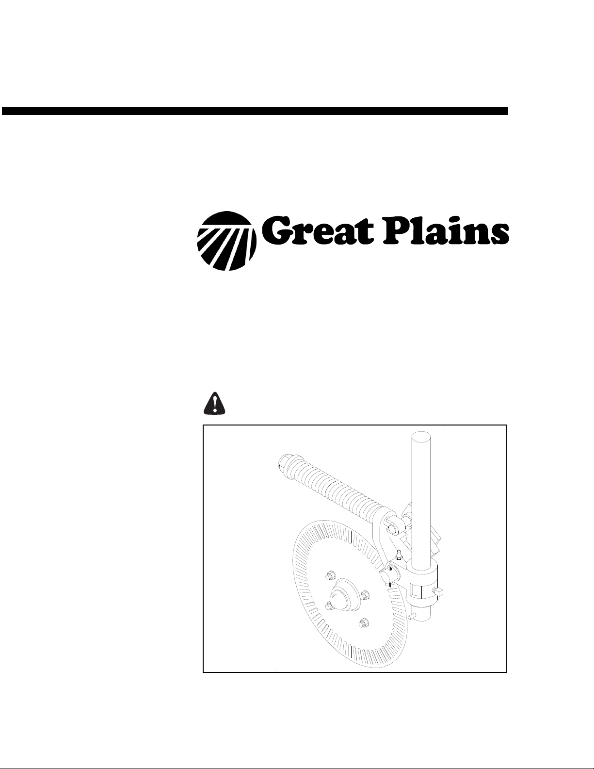
Operator’s/Parts Manual
Heavy Duty
Fertilizer Coulter
Planting Components
Read the operator manual entirely. When you see this symbol, the subsequent
instructions and warnings are serious - follow without exception. Your life and
the lives of others depend on it!
Illustrations may show optional equipment not supplied with standard unit.
© Copyright 2011 Printed 7/19/2011
10469
204-308M
Page 2

Table of Contents
General Information . . . . . . . . . . . . . . . . . . . . . . . . .1
Introduction . . . . . . . . . . . . . . . . . . . . . . . . . . . . . . . .2
Using This Manual. . . . . . . . . . . . . . . . . . . . . . . . .2
Important Safety Information . . . . . . . . . . . . . . . . . .3
Owner’s Assistance . . . . . . . . . . . . . . . . . . . . . . . . .4
Operating, Assembly Instr. & Adjustments . . . . . . .5
General Operation & Repair . . . . . . . . . . . . . . . . .5
Assembly Instruction . . . . . . . . . . . . . . . . . . . . . . .6
Spring Adjustments . . . . . . . . . . . . . . . . . . . . . . .6
Maintenance & Lubrication . . . . . . . . . . . . . . . . . . .7
Maintenance . . . . . . . . . . . . . . . . . . . . . . . . . . . . .7
Storage . . . . . . . . . . . . . . . . . . . . . . . . . . . . . . . . .7
Lubrication . . . . . . . . . . . . . . . . . . . . . . . . . . . . . .7
Parts . . . . . . . . . . . . . . . . . . . . . . . . . . . . . . . . . . . . . .8
Heavy Duty Fertilizer Coulters . . . . . . . . . . . . . . .8
Rectangular Tubing Clamp Kits . . . . . . . . . . . . .10
Diamond Bar Clamp Kits . . . . . . . . . . . . . . . . . . .12
Appendix . . . . . . . . . . . . . . . . . . . . . . . . . . . . . . . . .14
Warranty . . . . . . . . . . . . . . . . . . . . . . . . . . . . . . . . . .15
© Copyright 2011 All rights Reserved
Great Plains Manufacturing, Inc. provides this publication “as is” without warranty of any kind, either expressed or implied. While every precaution has been taken in the
preparation ofthis manual,Great Plains Manufacturing, Inc.assumes no responsibility forerrors or omissions. Neither is any liability assumed for damages resulting from
the use of the information contained herein. Great Plains Manufacturing, Inc. reserves the right to revise and improve its products as it sees fit. This publication describes
the state of this product at the time of its publication, and may not reflect the product in the future.
Great Plains Manufacturing, Incorporated Trademarks
The following are trademarks of Great Plains Mfg., Inc.: Application Systems, Ausherman, Land Pride, Great Plains
All other brands and product names are trademarks or registered trademarks of their respective holders.
Printed in the United States of America.
7/19/2011
204-308M
Page 3

General Information
Important Notice
Great Plains Manufacturing, Inc. provides this
publication “as is” without warranty of any kind, either expressed or implied, while every precaution
has been taken in the preparation of this manual,
Great Plains Manufacturing, Inc. assumes no responsibility for errors or omissions. Neither is any
liability assumed for damages resulting from the
use of the information contained herein. Great
Plains Manufacturing, Inc. reserves the right to revise and improve its products as it sees fit. This
publication describes the state of this product at
the time of its publication, and may not reflect the
product at all times in the future.
Printed in the United States of America.
For your convenience, record your Model and the
Date Purchased on page 4. Have this information
before you when calling aGreat PlainsAuthorized
Dealer.
General Information
1
This Operator’s Manual applies to the
Product Name listed below:
Heavy Duty Fertilizer Coulter
Reading this Manual
For your safety and to help in developing a better
understanding of your equipment we highly recommend that you read the operator sections of
this manual. Reading these sections not only provides valuable training but also familiarizes you
with helpful information and its location. The parts
sections are for reference only and don’t require
cover to cover reading. After reviewing your manual store it in a dry, easily accessible location for
future reference.
7/19/2011
204-308M
Page 4

Heavy Duty
2
Introduction
Great Plains welcomes you to its growing family of
new product owners. This Heavy Duty Fertilizer
Coulter has been designed with care and built by
skilled workers using quality materials. Proper
setup, maintenance and safe operating practices
will help you get years of satisfactory use from the
machine.
Description of Unit
The parts on your Heavy Duty Fertilizer Coulter
have been specially designed and should only be
replaced with genuine Great Plains parts. Therefore, should your Heavy Duty Fertilizer Coulter
requirer replacement parts go to your Great
Plains Dealer.
Using This Manual
This manual will familiarize you with safety, assembly, operation, adjustments and maintenance.
Read this manual and follow the recommendations to help ensure safe and efficient operation.
The information in this manual is current at printing. Some parts may change to assure top
performance.
Definitions
The following terms are used throughout this
manual.
Right-hand and left-hand as used in this manual
are determined by facing the direction the machine will travel while in use unless otherwise
stated.
A crucial point of information related to the preceding topic. For safe and correct operation, read and
follow the directions provided before continuing.
NOTE: Useful information related to the preceding topic.
204-308M
7/19/2011
Page 5
Important Safety Information
Look for Safety Symbol
The SAFETY ALERT SYMBOL indicates there is
a potential hazard to personal safety involved and
extra safety precaution must be taken. When you
see this symbol, be alert and carefully read the
message that follows it. In addition to design and
configuration of equipment, hazard control and
accident prevention are dependent upon the
awareness, concern, prudence and proper training of personnel involved in the operation,
transport, maintenance and storage of
equipment.
Be Aware of Signal Words
Signal words designate a degree or level of hazard seriousness.
Important Safety Information
3
DANGER indicates an imminently hazardous situation which, if not avoided, will result in death or
serious injury. This signal word is limited to the
most extreme situations, typically for machine
components that, for functional purposes, cannot
be guarded.
WARNING indicates a potentially hazardous situation which, if not avoided, could result in death or
serious injury, and includes hazards that are exposed when guards are removed. It may also be
used to alert against unsafe practices.
CAUTION indicates a potentially hazardous situation which, if not avoided, may result in minor or
moderate injury. It may also be used to alert
against unsafe practices.
7/19/2011
204-308M
Page 6

Heavy Duty
4
Owner Assistance
If you need customer service or repair parts, contact a Great Plains dealer. They have trained
personnel, repair parts and equipment specially
designed for Great Plains products.
Your machine’s parts were specially designedand
should only be replaced with Great Plains parts.
Always use the model number when ordering
parts from your Great Plains dealer.
Record your Model and Date Purchased here for
quick reference:
Model:________________________________
Date Purchased:_________________________
Your Great Plains dealer wants you to be satis-
fied with your new machine. If you do not
understand any part of this manual or are not satisfied with the service received, please take the
following actions.
1. Discuss the matter with your dealership service manager. Make sure they are aware of
any problems so they can assist you.
2. If you are still unsatisfied, seek out the owner
or general manager of the dealership.
3. For further assistance write to:
Product Support
Great Plains Mfg. Inc., Service Department
PO Box 5060
Salina, KS 67402-5060
204-308M
7/19/2011
Page 7

Operating, Assembly Instructions and
Adjustments
Operating, Assembly Instructions and Adjustments
Most accidents are the result of negligence and
carelessness, usually caused by failure of the operator to follow simple but necessary safety
precautions. The following safety precautions are
suggested to help prevent such accidents. The
safe operation of any machinery is a big concern
to consumers and manufactures.Your Heavy
Duty Fertilizer Coulter has been designed with
many built-in safety features. However, no one
should operate this product before carefully reading this Operators Manual.
General Operation & Repair
Never allow the Heavy Duty Fertilizer Coulter to
be operated by anyone who is unfamiliar with the
operation of all functions of the unit. All operators
should read and thoroughly understand the instructions given in this manual prior to moving the
unit.
5
1. Make sure safety rules are understood before
operating machinery or tractor.
2. Never permit any persons other than the op-
erator to ride on the tractor.
3. Never permit any persons to ride on or stand
near the drill while it is in operation.
4. Regulate your speed to the field conditions,
maintaining complete control at all times.
5. After repairing or adjusting, make sure all
tools and parts are removed from the implement before attempting to operate it.
6. Do not grease or oil machine while it is in op-
eration.
7. Loose fitting clothing should not be worn as it
may catch in moving parts.
8. Never dismount from a moving tractor.
9. Do not leave the tractor or the implement un-
attended with the engine running.
10. Do not stand between the tractor and the im-
plement during hitching.
7/19/2011
11. Detach and store implements in an area
where children normally do not play. Stabilize
implements by using suitable supports and
block wheels.
204-308M
Page 8

Heavy Duty
6
12. If a hydraulic leak develops, correct it immediately. Escaping hydraulic oil can have extremely high pressure. A stream of high
pressure oil may easily penetrate the skin as
with modern needle-less vaccination equipment - but with the exception that hydraulic
fluid may cause blood poisoning. It is imperative that the connections are tight and that all
lines and pipes are in good condition. If an injury is caused by the escaping hydraulic fluid,
see doctor at once!
13. Use a piece of cardboard or wood to detect
leaks of hydraulic oil under pressure.
14. Be sure to relieve all hydraulic pressure before
disconnecting any lines or pipes between the
implement and the tractor hydraulic system.
Keep all guards and shields in place.
Assembly Instructions
Refer to Figure 1
1. Mount coulter blade (5) to hub using carriage
bolt (8) and fasteners (6) & (7). Tighten nuts.
2. Lock set screw (3) in swivel collar (4) onto the
vertical shaft (1), (purchased separately) with
roll pin below swivel mounting casting (2).
3. Mount clamp brackets (purchased separately) with coulter vertical shaft to tool bar. Adjust vertically and align with unit as desired,
so coulter assembly is running true with unit.
Spring Adjustments
No spring adjustment is necessary on this unit.
Initial operating force to move coulter upwards is
540 pounds. The preload has proved to be more
than adequate for most No-Till conditions.
Any attempt to make coulter force greater than factory
setting, may contribute to premature failure of parts
and warranty shall be null and void.
204-308M
Figure 1
Assembly
20183
7/19/2011
Page 9

Maintenance and Lubrication
Maintenance and Lubrication
7
Maintenance
Proper servicing and adjustment is the key to the long
life of any farm implement. With careful and systematic
inspection, you can avoid costly maintenance, time and
repair.
1. After using your Heavy Duty Fertilizer Coulter for
several hours, check all bolts to be sure they are
tight.
2. Listed below are the items you need to lubricate every 20 hours of operation. Use a heavy duty multipurpose grease:
a. Grease zerk on hub.
b. Grease zerk on swivel mounting casting
Storage
1. Clean the Heavy Duty Fertilizer Coulter as necessary.
2. Lubricate zerks as indicated in the following Illustrations.
3. Store the Heavy Duty Fertilizer Coulter inside if possible for longer Heavy Duty Fertilizer Coulter life.
Lubrication
Lubrication Symbols
20
Lubrication is required every 20 hours of operation.
Seasonally
12454
12455
Hub
Type of Lubrication: Heavy duty multi-purpose grease
8
Swivel Mounting Casting
Type of Lubrication: Heavy duty multi-purpose grease
7/19/2011
204-308M
Page 10

Heavy Duty
8
Parts
Heavy Duty Fertilizer Coulters (Effective July 1, 2011+)
204-308M
32229
7/19/2011
Page 11

Ref. Part No. Description
1 149-044D COULTER STOP
2 149-558D COULTER SPRING WASHER
3 149-559D SPRING 2.25 O.D. X .5 COIL
4 204-379S COULTER HUB PACKAGE
5 249-051H CLTR SWING ARM WLMT Used on RH.
5 249-237H LH COULTER SWING ARM WLMT Used on LH.
6 249-225S PVT CLTR CASTING MOUNT ASY RH Used on RH.
6 249-226S PVT CLTR CASTING MOUNT ASY LH Used on LH.
7 800-001C GREASE ZERK STRAIGHT 1/4-28
8 800-164C SNAP RING 3/4 EXTERNAL HEAVY
9 800-177C SNAP RING EXT 1 1/4 HEAVY
10 801-083C SCREW SET 5/8-11X1 1/2 GR8 CUP
11 802-214C RHSNB 1/2-13X1 1/4 GR5
12 802-718C EYE BOLT 3/4-10X14 3/4 LG SP
13 803-020C NUT HEX 1/2-13 PLT
14 803-023C NUT HEX JAM 5/8-11 PLT
15 803-029C NUT HEX SLOTTED 7/8-14 PLT
16 803-048C NUT HEX JAM 3/4-10 PLT
17 804-015C WASHER LOCK SPRING 1/2 PLT
18 804-055C WASHER SPINDLE - 7/8
19 804-156C WASHER MACH 1 1/4X3/4X14GA
20 804-165C WASHER MACH 1 7/8X1 1/4X 14GA
21 805-017C PIN COTTER 3/16 X 1 3/4 PLT
22 805-043C PIN SPIROL 3/8X2 1/2 PLAIN
23 805-331C COULTER SPRING GUIDE TUBE
24 817-513C BUSHING 1X3/4X1 1/8 FLG HD
25 838-482C DECAL GP PLANTING COMPONENTS
26 200-039V COULTER HUB & CUP ASSY
27 816-009C OIL SEAL DOUBLE LIP
28 822-021C BRG CONE 1.25ID LM-67048
29 822-020C BRG CUP LM-67010
30 820-018C COULTER BLADE FLUTED
31 200-001D HUB GREASE CAP
32 204-026D SHANK 1 1/2D X 22 FERT COULT
33 820-132C 1 1/2 X 22 OFFSET SHANK
Parts
9
7/19/2011
204-308M
Page 12

Heavy Duty
10
Heavy Duty Fertilizer Coulters (Effective June 30, 2011-)
204-308M
10494
7/19/2011
Page 13

Ref. Part No. Description
1. 803-025C NUT HEX 3/4-10 PLT NYLOCK
2. 812-031C CASTING COULTER SPRING WASHER
3. 204-107D SPRING ROD SLEEVE 1 1/8 OD
4. 807-074C SPRING 2.25 OD X .5 COIL
5. 817-029C BUSHING COULTER CASTING
6. 149-963S COULTR MOUNT, CASTNG ASSY
7. 800-001C GREASE ZERK STRAIGHT 1/4-28
8. 204-026D SHANK 1 1/2D X 22 FERT COULT
9. 820-132C 1 1/2 X 22 OFFSET SHANK
10. 805-043C PIN SPIROL 3/8X2 1/2 PLAIN
11. 204-075H COULTER SPRING ROD WLDMT
12. 801-040C SCREW SQ HD 5/8-11 X 1 CUP PT
13. 149-162H COULTER STOP WELDMENT
14. 804-039C WASHER FLAT 1 1/4 SAE PLT
15. 805-021C PIN COTTER 1/4 X 2 PLT
16. 803-181C NUT HEX FLANGE LOCK 3/4-10 PLT
17. 817-051C SWING ARM BUSHING
18. 149-181E CLTR SWG ARM WD REPLBY149-181E
19. 816-009C OIL SEAL DOUBLE LIP
20. 822-021C BEARING CONE LM-67048
21. 822-020C BEARING CUP LM-67010
22. 802-106C RHSNB 1/2-13X1 1/2 GR5
23. 200-039V COULTER HUB & CUP ASSY
24. 804-055C WASHER SPINDLE - 7/8
25. 820-018C COULTER BLADE FLUTED
26. 804-015C WASHER LOCK SPRING 1/2 PLT
27. 803-020C NUT HEX 1/2-13 PLT
28. 200-001D HUB GREASE CAP
29. 805-017C PIN COTTER 3/16 X 1 3/4 PLT
30. 803-029C NUT HEX SLOTTED 7/8-14 PLT
31. 200-002S COULTER HUB PACKAGE
32. 838-482C DECAL GP PLANTING COMPONENTS
Parts
11
7/19/2011
204-308M
Page 14

Heavy Duty
12
Rectangular Tubing Clamp Kits
NOTE: To find your clamp kit match the height and width of your mounting tube to the chart below
Part No. Width Height
204-017K
204-018K
204-021K
204-022K
2 1/2” X 2 1/2”
2” X 6”
4” X 4”
3” X 7”
204-023K 5” X 7”
204-024K
204-054K
204-064K
204-340K
204-355K
7” X 7”
6” X 4”
3" X 3"
3" X 6"
4" X 6"
204-308M
12449
7/19/2011
Page 15

Ref. Part No. Description
1. 802-249C HHCS 1/2-13X4 1/2 GR5 SPTHD (204-017K Clamp Kit Only)
802-044C HHCS 1/2-13X4 GR5 (204-018K Clamp Kit Only)
802-047C HHCS 1/2-13X6 GR5 (204-021K and 204-355K Clamp Kits Only)
802-289C HHCS 1/2-13X8 GR5 (204-054K Clamp Kit Only)
802-045C HHCS 1/2-13X5 GR5 (204-022K, 204-340K and 204-064K Clamp Kits Only)
802-260C HHCS 1/2-13X7 GR5 (204-023K Clamp Kit Only)
802-269C HHCS 1/2-13X9 GR5 (204-024K Clamp Kit Only)
2. 804-015C WASHER LOCK SPRING 1/2 PLT
3. 204-037D CLAMP PLT 3 1/2 SQ BAR (204-017K Clamp Kit Only)
204-039D CLAMP PLT 6 BAR (204-018K, 204-355K and 204-340K Clamp Kits Only)
204-038D CLAMP PLT 4 BAR (204-021K & 204-054K Clamp Kits Only)
204-040D CLAMP PLT 7 BAR (204-022K, 204-023K & 204-024K Clamp Kits Only)
204-083D CLAMP PLATE 3 SQ BAR (204-064K Clamp Kit Only)
4. 204-072D CLAMP SHANK 1 1/2 DIA
5. 801-040C SCREW SQ HD 5/8-11 X 1 CUP PT
Parts
13
7/19/2011
204-308M
Page 16

Heavy Duty
14
Diamond Bar Clamp Kits
NOTE: To find your clamp kit match your diamond bar tube to the chart below
Part No. Bar
204-019K
204-020K
Size
3 1/2”
3”
204-308M
12450
7/19/2011
Page 17

Ref. Part No. Description
1. 802-260C HHCS 1/2-13X7 GR5 (204-019K Clamp Kit Only)
802-289C HHCS 1/2-13X8 GR5 (204-020K Clamp Kit Only)
2. 804-015C WASHER LOCK SPRING 1/2 PLT
3. 204-064D CLAMP PLATE 3 DIA BAR (204-019K Clamp Kit Only)
204-041D CLAMP PLT 3 1/2 DIA BORE (204-020K Clamp Kit Only)
4. 204-077H ADAPTER PLT WLDMNT 3 DIA BAR (204-019K Clamp Kit Only
204-079H ADAPTER PLT WLDMT 3 1/2DIA BAR (204-020K Clamp Kit Only)
5. 204-072D CLAMP SHANK 1 1/2 DIA
6. 801-040C SCREW SQ HD 5/8-11 X 1 CUP PT
Parts
15
7/19/2011
204-308M
Page 18

Heavy Duty
16
204-308M
20120
7/19/2011
Page 19

Appendix
Torque Values Chart
Bolt Head Identification
Bolt Head Identification
Appendix
17
Bolt Size
(Inches)
1
in-tpi
1/4" - 20 7.4 5.6 11 8 16 12 M 5 X 0.8 4 3 6 5 9 7
1/4" - 28 8.5 6 13 10 18 14 M 6 X 1 7 5 11 8 15 11
5/16 - 18 15 11 24 17 33 25 M 8 X 1.25 17 12 26 19 36 27
5/16" - 24 17 13 26 19 37 27 M 8 X 1 18 13 28 21 39 29
3/8" - 16 27 20 42 31 59 44 M10 X 1.5 33 24 52 39 72 53
3/8" - 24 31 22 47 35 67 49 M10 X 0.75 39 29 61 45 85 62
7/16" - 14 43 32 67 49 95 70 M12 X 1.75 58 42 91 67 125 93
7/16" - 20 49 36 75 55 105 78 M12 X 1.5 60 44 95 70 130 97
1/2" - 13 66 49 105 76 145 105 M12 X 1 90 66 105 77 145 105
1/2" - 20 75 55 115 85 165 120 M14 X 2 92 68 145 105 200 150
9/16" - 12 95 70 150 110 210 155 M14 X 1.5 99 73 155 115 215 160
9/16" - 18 105 79 165 120 235 170 M16 X 2 145 105 225 165 315 230
5/8" - 11 130 97 205 150 285 210 M16 X 1.5 155 115 240 180 335 245
5/8" - 18 150 110 230 170 325 240 M18 X 2.5 195 145 310 230 405 300
3/4" - 10 235 170 360 265 510 375 M18 X 1.5 220 165 350 260 485 355
3/4" - 16 260 190 405 295 570 420 M20 X 2.5 280 205 440 325 610 450
7/8" - 9 225 165 585 430 820 605 M20 X 1.5 310 230 650 480 900 665
7/8" - 14 250 185 640 475 905 670 M24 X 3 480 355 760 560 1050 780
1" - 8 340 250 875 645 1230 910 M24 X 2 525 390 830 610 1150 845
1" - 12 370 275 955 705 1350 995 M30 X 3.5 960 705 1510 1120 2100 1550
1-1/8" - 7 480 355 1080 795 1750 1290 M30 X 2 1060 785 1680 1240 2320 1710
1 1/8" - 12 540 395 1210 890 1960 1440 M36 X 3.5 1730 1270 2650 1950 3660 2700
1 1/4" - 7 680 500 1520 1120 2460 1820 M36 X 2 1880 1380 2960 2190 4100 3220
1 1/4" - 12 750 555 1680 1240 2730 2010
1 3/8" - 6 890 655 1990 1470 3230 2380
1 3/8" - 12 1010 745 2270 1670 3680 2710
1 1/2" - 6 1180 870 2640 1950 4290 3160
1 1/2" - 12 1330 980 2970 2190 4820 3560
Grade 2 Grade 5
N · m2ft-lb3N · m ft-lb N · m ft-lb mm x pitch4N · m ft-lb N · m ft-lb N · m ft-lb
Torque tolerance + 0%, -15% of torquing values. Unless otherwise specified use torque values listed above.
Grade 8
Bolt Size
(Metric)
1
in-tpi = nominal thread diameter in inches-threads per inch
4
mm x pitch = nominal thread diameter in millimeters x thread pitch
5.8 8.8 10.9
Class 5.8 Class 8.8 Class 10.9
2
N· m = newton-meters
3
ft-lb= foot pounds
7/19/2011
204-308M
Page 20

Heavy Duty
18
Warranty
Great Plains Manufacturing, Incorporated warrants to the original purchaser that this seeding equipment will be free from defects in material
and workmanship for a period of one year from the date of original purchase when used as intended and under normal service and conditions
for personal use; 90 days for commercial or rental purposes. This Warranty is limited to the replacement of any defective part by Great Plains
Manufacturing, Incorporated and the installation by the dealer of any
such replacement part. Great Plains reserves the right to inspect any
equipment or part which are claimed to have been defective in material
or workmanship.
This Warranty does not apply to any part or product which in Great
Plains’ judgement shall have been misused or damaged by accident or
lack of normal maintenance or care, or which has been repaired or altered in a way which adversely affects its performance or reliability, or
which has been used for a purpose for which the product is not designed. This Warranty shall not apply if the product is towed at a speed
in excess of 20 miles per hour.
Claims under this Warranty must be made to the dealer which originally
sold the product and all warranty adjustments must by made through
such dealer. Great Plains reserves the right to make changes in materials or design of the product at any time without notice.
This Warranty shall not be interpreted to render Great Plains liable for
damages of any kind, direct, consequential, or contingent, to property.
Furthermore, Great Plains shall not be liable for damages resulting from
any cause beyond its reasonable control. This Warranty does not extend to loss of crops, losses caused by harvest delays or any expense
or loss for labor, supplies, rental machinery or for any other reason.
No other warranty of any kind whatsoever, express or implied, is
made with respect to this sale; and all implied warranties of merchantability and fitness for a particular purpose which exceed
the obligations set forth in this written warranty are hereby disclaimed and excluded from this sale.
This Warranty is not valid unless registered with Great Plains Manufacturing, Incorporated within 10 days from the date of original purchase.
204-308M
7/19/2011
Page 21

Great Plains Manufacturing, Inc.
Corporate Office: P.O. Box 5060
Salina, Kansas 67402-5060 USA
 Loading...