

Page 1

Assembly Instructions for the Ultra-Till
2/26/04
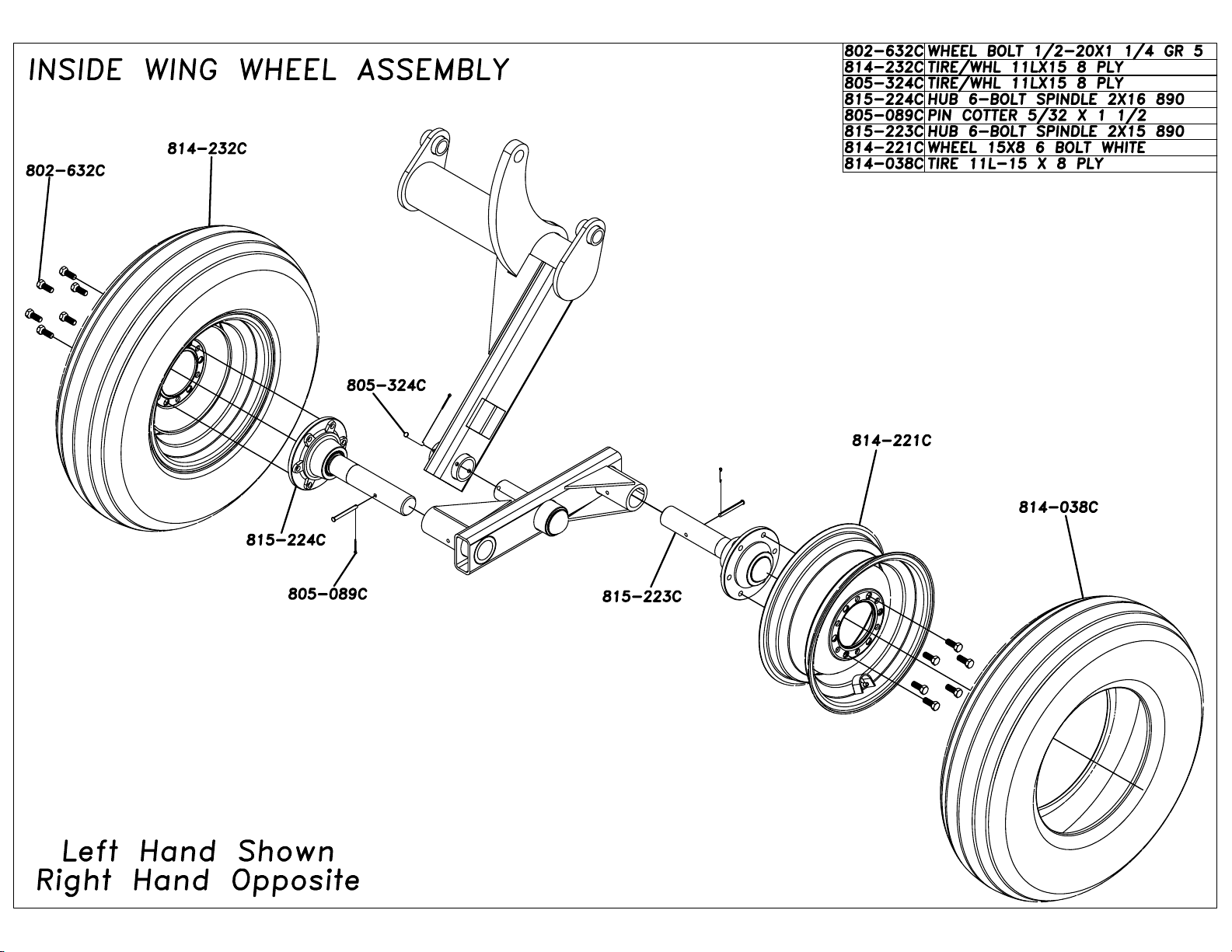
Thank you for purchasing the Great Plains Ultra-Till. To finish assembly you must first mount
the tires to the inside wings. Mount the tires as shown in layout (Inside Wing Wheel Assembly.) The
hub assemblies with the smaller titan tires pre-mounted get pinned on the caster wheel assemblies as
shown in layout (Caster Wheel Assembly – UT5042, UT5048, UT5052 ONLY.)
Then you must locate the correct coulter/disc gang assembly. The assembly should come to you
with a part number written on the gang. Simply match the part number on the gang frame with the
number located on the respective assembly layout and assemble as shown on the coulter/disc gang setup.
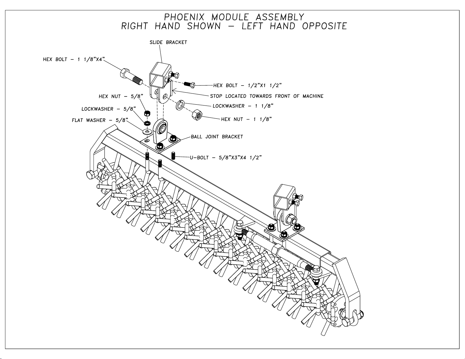
The next step is to start assembling the ball joint brackets on the phoenix module, so they can be
hung on the Ultra-Till frame. Assemble ball joint brackets as shown on (Phoenix Module Assembly.)
Leave all the nuts loose so the ball joint bracket can slide on phoenix module. On the end of the phoenix
module there is a number written in white paint. This will assist you in location of these modules.
Simply match the number on the side of the phoenix module to the number given in the respective
layout and assemble accordingly. Once phoenix module is hung tighten nuts on ball joint bracket to the
x dimension given for each individual module. This will place the phoenix modules in the correct
location and alignment. Once this is done, double check the machine with the layouts provided and
make sure there is no interference. This should complete the assembly of your Great Plains Ultra-Till.
Page 2
Page 3
Page 4

Page 5

Page 6

Page 7

Page 8

Page 9

Page 10

Great Plains Mfg., Inc. Section 2: Hydraulics
5-Section Ultra Till Hydraulic Down Pressure Preparation and Setup
Note: This setup procedure is for tractors with closed-center or pressure compensated flow
hydraulic systems. For open-center hydraulic systems contact your dealer for instructions.
1. Adjust the bypass valve by turning knob
(1), Figure 2, clockwise all the way in and
then backing out 1 full turn.
2. On tractor, adjust flow-control valve to low
side of flow rate. NOTE: The faster the
flow of oil through the system the greater
potential for oil heating, premature wear
or tractor damage.
3. Lock the fold hydraulic lever for
continuous downward oil flow.
4. Adjust pressure reducing valves knob (2
& 3) on implement so the pressure
gauges reads 1200 psi each. Never
exceed 1400 psi.
5. While watching pressure gauges, slowly
open bypass valve, knob (1) until gauges
reads around 1100 psi. Pressure might rise
and then fall off as knob is opened. If
pressure exceeds 1400 psi during this step,
the tractor flow is too high, reduce tractor
flow. Lock bypass valve knob (1) at 1100 psi.
6. Finally adjust valve knobs (2 & 3) to the
desired wing down pressure setting of 400 to
700 psi. Never exceed 900 psi.
7. In field operation, Lock the fold
hydraulic lever for continuous
downward oil flow. If wings are
running too high, increase pressure
setting to the appropriate valve, knob
(2 or 3), to level machine. If center is
too high, decrease pressure setting
with knob (2) on Inside wing valve.
Figure 2
3/11/2004 Series I UT3030-UT5052 Ultra Till 786-026M
41
 Loading...