

Page 1
Great Plains Manufacturing, Inc. 1
Universal Acre Meter
Installation Instructions
General Information
These Instructions explain how to install the 589-415A
Acre Meter Kit Wheel or the 589-427A Gang Mount Acre
Meter Kit. The acre meter program chart applies to the
meter being mounted on wheel or turbo blade.
Tools Required
• Basic Hand Tools
• Lug Wrench or Air Impact
• Torque Wrench
Models Covered
Turbo-Till Disk Harrow
Turbo-Chopper Plains Plow
Turbo Max Field Cultivator
Turbo Chisel
Discovator
Discovator DVN
.
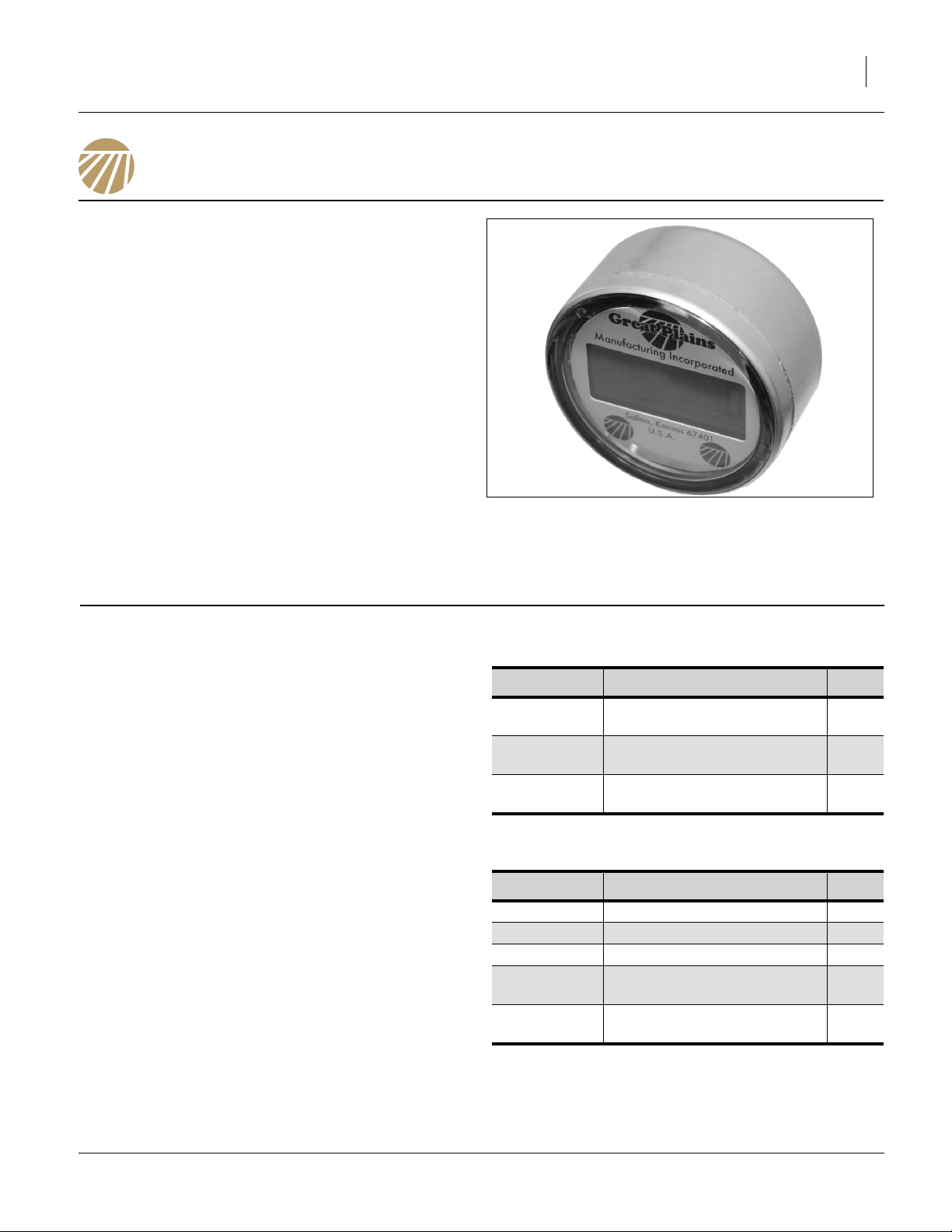
Figure 1
Electronic Acremeter
27378
589-415A Acre Meter Kit Wheel
Part Number
586-593D
586-594D
891-420C
ELECTRONIC ACRE/HECT-
Description Qty.
8 - BOLT HUBOMETER
MOUNT
6 - BOLT HUBOMETER
MOUNT
ARE METER
589-427A Gang Mount Acre Meter Kit
Part Number
589-151D PART ACRE METER 1
589-428H ACRE METER SUB ASSY 1
802-183C RHSNB 1/2-13X1 GR5 2
803-342C
891-420C
ELECTRONIC ACRE/HECT-
Description Qty.
NUT HEX TOP LOCK 1/2-
13PLT
ARE METER
1
1
1
2
1
01/21/2014 589-414M
Page 2
2 Acre Meter Great Plains Manufacturing, Inc.
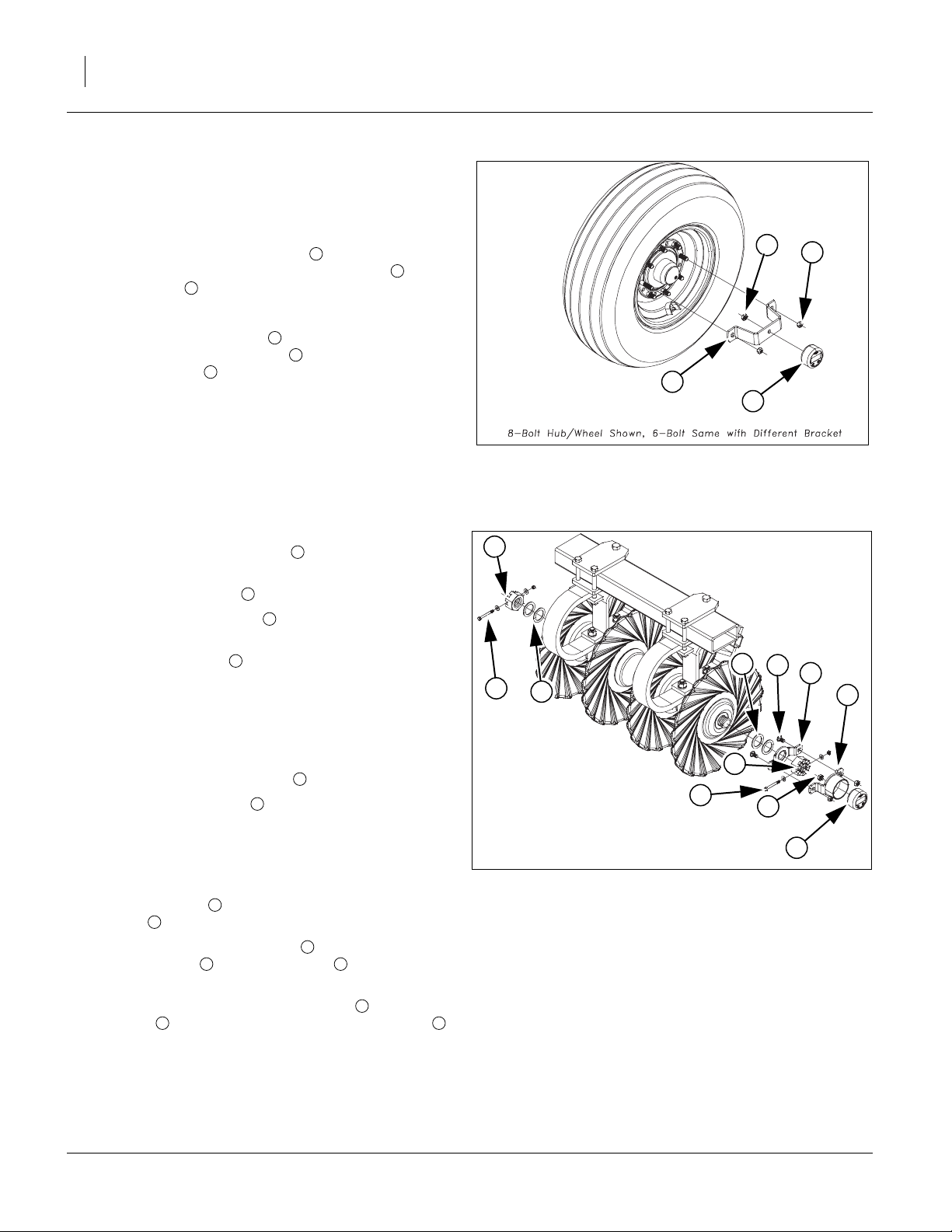
Refer to Figure 2
Note: The wheel mount will bolt on the same for either a 6 or
8 bolt wheel but will use either the 596-594D for6-bolt
and the 596-593D for 8-bolt. Mount acre meter on either outside wing wheel.
1. Bolt the 891-420C acre meter to the appropriate
596-593D or 596-594D hubometer mount with the
1/2 lock nut provided with acre meter.
2. Tighten top lock nut to secure to bracket.
3. Take two of the lug nuts (opposite of the first one)
off, slide hubometer mount over lug bolts and reinstall lug nuts turned around with flat part of nut
against mount.
Note: Torque lug nuts to specs. 1/2”-20 (75-85 ft-lbs), 9/16”-
18 (80-90 ft-lbs), 5/8”-18 (85-100 ft-lbs).
3
4
1
2
4
2
2
3
4
1
Refer to Figure 3
4. Remove the castle nut bolts from both ends of
gangs.
5. Remove castle nuts from both ends of gangs.
6. Remove 2 flat washers or 1/4” thickness from
opposite end of duratight washer.
7. Leave all washers on duratight end, unless opposite end does not have at least 2 washers, then
washer may be removed from this end.
Note: When the 589-151D bracket is used on a 1 3/4” gang
bolt, the center knock will need removed to fit over
gang bolt.
8. Slide the 589-151D bracket over gang bolt.
9. Re attach castle nuts on both ends and tighten.
Note: Torque 1 3/4”-5 gang bolt to 850 Foot-pounds (165
lbs on 5’ cheater) or 1 1/2-6 750 Foot-pounds (175
lbs on 4’ cheater). Align slot in castle nut with hole in
gang bolt.
10. Re attach bolts with a flat washer, one each of castle nut , secure with lock nut.
11. Attach 891-420C acre meter to 589-428H acre
meter bracket with 1/2 lock nut provided with
acre meter.
12. Attach 589-428H acre meter bracket to 589-151D
bracket , secure with 802-183C carriage bolts
and 803-342C top lock nuts.
2
5 9
2
4
1
7 8
1
3
5
2
6
7
Figure 2
Wheel Hub Assembly
42289
2
4
9
1
3
5
7
2
1
8
6
Figure 3
Gang Mount Assembly
42394
589-414M 01/21/2014
Page 3
Great Plains Manufacturing, Inc. 3
Electronic Hubodometer
To program the electronic hubodometer use the magnetic programming tool included with the meter. A typical
permanent magnet will also work. The tool is used to initialize and configure the hubodometer bu touching it to
sensor locations on the face of the meter. The hubometer is versatile enough to work with any tire size as well
Programming Mode
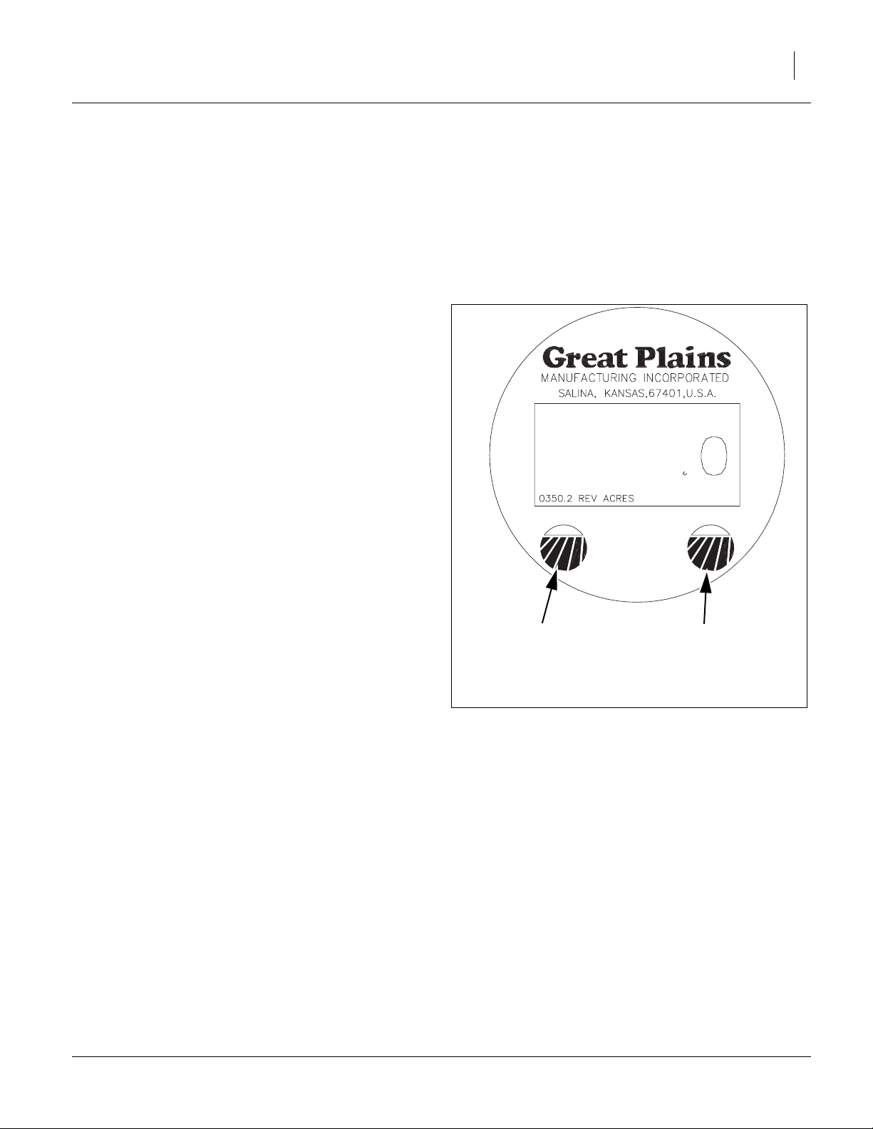
Refer to Figure 4
• The unit enters programming mode when the magnetic
programming tool is held on the left sensor for 6 seconds.
• The display will turn on and show the serial number for 6
seconds. If the programming magnet is continuously
applied during the time the serial number is shown and
for an additional 8 seconds, the meter will wait for the
magnet to be drawn and then will enter the programming
mode.
• Once active, there is a 10 second time-out if no further
user input is received and the unit returns to the previous
mode.
• The display will show the prompt PROG. Each tap on the
left Mode button advances the programming mode to the
next mode. While programming the meter each tap on the
right sensor changes the current item based on the
mode.
Mode 1: Set Unit of Measure
• The display shows “UNITS” and the current measurement unit of measure. All other display features are off. To
change unit of measure tap the right sensor to toggles
through each unit of measure mode (HECTARES,
MILES, KILOMETERS, and back to ACRES). Tapping left
mode button again changes to Mode 2.
Mode 2: Set Counter Ratio
Note: To find the correct ratio value for your machine see
the Acre Meter Conversion Chart on next page.
• This mode is used to set the counter ratio for the unit
of measure that is currently displayed. All display features are off except the ratio number (showing the current ratio value). The left most digit of the ratio will be
flashing. To change the digit value, tap the right sensor. The digit will then incrament. Continue to tap the
right sensor to increment to the desired value.
• To select a different digit tap the left program sensor to
sequence through the digits and then tap the right
sensor when the desired digit is flashing to increment
the value as above/ When programming each digit a
change from 9 to 0 does not affect the next digit. Tapping the left mode button again advances to the next
digit. Once the right most digit has been passed the
as to be adjusted for applications with the unit of measure in miles, kilometers, acres and hectares. Use the
Acre Meter Conversion Chart (for working width and tire
size) along with the Programming Mode instructions to
program the Acre Meter.
Use left mode button
to enter and toggle
through the
programming modes
Figure 4
Use right mode button to toggle through
selection settings in
the individual modes
27380
Meter Display
display shows the entered value. Tapping the left
mode button again changes to Mode 3.
Mode 3: Preset
• At this point the user can set the meter to the desired
starting count. This does affect non-resettable back
ground total. The factory default is “000000” if this feature is not needed, tap the left target repeatedly and
leave the digits set to zero. Tapping the right target will
increment the digit. Tapping the left target once will
move it to the next digit to the right. When all the digits
are set, tapping the left target once more will make the
display show: Example: set to 125750.
Mode 4: Security Lock
• This is where the user will turn on or off the security
lock feature. Tapping the right target will toggle it
between “ON” and “OFF”. Warning-If the Security lock
feature is set to “ON” when the units leave the program
01/21/2014 589-414M
Page 4

4 Acre Meter Great Plains Manufacturing, Inc.
mode, the unit will never enter the program mode
again. If an error was made, the unit will need to be
replaced. The serial # and the background total however are still viewable by holding the magnet on the left
target as described above.
• If the security feature is left off, tapping the left target
once more will make the display show PROG.
• PROG will be display for about 10 seconds. If a programming error was made, tapping the left target once
more before the 10 seconds has elapsed will send the
RT1000 back to the beginning of the program mode
where the error can be corrected if need be. At this
point leaving the RT1000 untouched will allow it to
leave the programming mode and after 10 seconds
the display will show: Example: 125750.0 (or preset
value).
• If the security feature is turned on, tapping the left target once more will make the display show y n. The
unit is now asking you to confirm that you want the
security feature on. Tap the left target for YES, the
right target for NO. Tapping the left target (y) will make
the display exit the program mode and lock the unit.
The display will show: Example 125750.0 (or preset
value).
• Tapping the right target (n) will return the display to
SEC OFF.
Exiting Program Mode
• When the PROG prompt is displayed and there is no
input activity for 10 seconds, the unit will return to the
previous state prior to entering programming mode.
Normal Operation
Idle (Wheel has not been turning)
• The electronic hubodometer waits in a low power consumption mode. The unit will go into active mode if
motion is detected or into programming mode if activated by a programming tool. The meter display is on
during idle mode and displays the current total. If the
meter is in idle mode for more than 1 hour the display
turns off until it is activated. To reactivate the display
after it has gone off, but before starting to turn again
touch the programming magnet to the left sensor.
Active Mode: Wheel starting to turn
• The display turns off once the wheel is turning. The
hubodometer monitors the wheel position by polling
the 2 Hall-Effect motion sensors at a sample rate that
is based on current speed of wheel.
Active Mode: Wheel stops turning
• When the meter is at rest for a minimum of 15 seconds, the display is enabled and shows the total count
and measurement units. The meter will enter idle
mode and after 1 hour of no activity the display will
turn off.
589-414M 01/21/2014
Page 5

Great Plains Manufacturing, Inc. 5
Acre Meter Conversion Chart
WORKING WIDTH 8' 9" 11' 3" 11' 8" 13' 2" 13' 9" 15' 6" 15' 8" 15' 11" 16' 3" 17' 8" 18' 18' 3" 18' 9" 20'
MODEL #'S TCN5107 TCN5309 1200TT 1200TM TCN5311 1500TC 1500TM 8315DVN TCN5313 1800TT 1800TM 8318DVN TC5115 8321DV
TIRE SIZE
6.70 X 15 725.87 564.57 544.41 482.38 461.92 409.77 405.41 399.04 390.86 359.51 352.86 348.02 338.74 317.57
9.5L X 15 688.24 535.30 516.18 457.38 437.97 388.52 384.39 378.35 370.59 340.87 334.56 329.98 321.18 301.11
11L X 15 693.84 539.65 520.38 461.09 441.53 391.68 387.52 381.43 373.60 343.65 337.28 332.66 323.79 303.55
12.5L X 15 645.83 502.31 484.37 429.19 410.98 364.58 360.70 355.04 347.76 319.87 313.95 309.65 301.39 282.55
10 - 16.5 656.48 510.59 492.36 436.27 417.76 370.59 366.65 360.89 353.49 325.14 319.12 314.75 306.36 287.21
33 X 15.5 -16.5 579.99 451.11 435.00 385.44 369.09 327.42 323.93 318.85 312.30 287.26 281.94 278.08 270.66 253.75
12.5L X 16.5 GALAXY 590.54 459.31 442.91 392.45 375.80 333.37 329.83 324.64 317.99 292.49 287.07 283.14 275.59 258.36
32 -15.5 X 16.5 GALAXY 594.24 462.19 445.68 394.91 378.16 335.46 331.89 326.68 319.98 294.32 288.87 284.91 277.31 259.98
380/55R16.5 579.99 451.11 435.00 385.44 369.09 327.42 323.93 318.85 312.30 287.26 281.94 278.08 270.66 253.75
440/55R18 515.00 400.55 386.25 342.24 327.72 290.72 287.63 283.11 277.31 255.07 250.34 246.92 240.33 225.31
20" Turbo Blade 963.54 749.42 722.65 640.33 613.16 543.93 538.15 529.69 518.83 477.22 468.39 461.97 449.65 421.55
22"Turbo Blade 865.79 673.39 649.34 575.37 550.96 488.75 483.55 475.96 466.19 428.81 420.87 415.10 404.03 378.78
WORKING WIDTH
MODEL #'S
TIRE SIZE
6.70 X 15 298.89 292.02 284.39 276.15 266.49 264.64 260.13 251.54 244.28 241.96 228.88 226.84 216.52 211.71
9.5L X 15 283.39 276.88 269.65 261.83 252.68 250.92 246.64 238.50 231.62 229.41 217.01 215.08 205.30 200.74
11L X 15 285.70 279.13 271.84 263.96 254.73 252.96 248.64 240.44 233.50 231.28 218.78 216.82 206.97 202.37
12.5L X 15 265.93 259.82 253.03 245.70 237.11 235.46 231.44 223.80 217.35 215.28 203.64 201.82 192.65 188.37
10 - 16.5 270.31 264.10 257.20 249.75 241.01 239.34 235.26 227.49 220.93 218.83 207.00 205.15 195.82 191.47
33 X 15.5 -16.5 238.82 233.33 227.24 220.65 212.94 211.46 207.85 200.99 195.19 193.33 182.88 181.25 173.01 169.17
12.5L X 16.5 GALAXY 243.17 237.58 231.37 224.66 216.81 215.30 211.63 204.64 198.74 196.85 186.21 184.54 176.16 172.24
32 -15.5 X 16.5 GALAXY 244.69 239.06 232.82 226.07 218.17 216.65 212.95 205.93 199.99 198.08 187.37 185.70 177.26 173.32
380/55R16.5 238.82 233.33 227.24 220.65 212.94 211.46 207.85 200.99 195.19 193.33 182.88 181.25 173.01 169.17
440/55R18 212.06 207.18 201.77 195.92 189.07 187.76 184.55 178.46 173.32 171.67 162.39 160.94 153.62 150.21
20" Turbo Blade 396.75 387.63 377.51 366.56 353.75 351.29 345.30 333.90 324.27 321.18 303.82 301.11 287.42 281.03
22"Turbo Blade 356.50 348.31 339.21 329.38 317.86 315.65 310.27 300.03 291.37 288.60 273.00 270.56 258.26 252.52
WORKING WIDTH
MODEL #'S
TIRE SIZE
6.70 X 15 208.24 207.11 198.48 195.43 192.47 190.54 183.21 178.91 176.43 160.79 158.78 156.82 151.22 148.57
9.5L X 15 197.45 196.37 188.19 185.30 182.49 180.66 173.71 169.64 167.28 152.46 150.55 148.69 143.38 140.87
11L X 15 199.05 197.97 189.72 186.80 183.97 182.13 175.13 171.02 168.64 153.70 151.78 149.90 144.55 142.01
12.5L X 15 185.28 184.27 176.59 173.88 171.24 169.53 163.01 159.18 156.97 143.06 141.28 139.53 134.55 132.19
10 - 16.5 188.33 187.31 179.51 176.74 174.07 172.33 165.70 161.81 159.56 145.42 143.60 141.83 136.77 134.37
33 X 15.5 -16.5 166.39 165.49 158.59 156.15 153.79 152.25 146.39 142.96 140.97 128.48 126.87 125.31 120.83 118.71
12.5L X 16.5 GALAXY 169.42 168.50 161.48 158.99 156.58 155.02 149.06 145.56 143.53 130.82 129.18 127.59 123.03 120.87
32 -15.5 X 16.5 GALAXY 170.48 169.55 162.49 159.99 157.56 155.99 149.99 146.47 144.43 131.64 129.99 128.39 123.80 121.63
380/55R16.5 166.39 165.49 158.59 156.15 153.79 152.25 146.39 142.96 140.97 128.48 126.87 125.31 120.83 118.71
440/55R18 147.74 146.94 140.82 138.65 136.55 135.19 129.99 126.94 125.17 114.08 112.66 111.26 107.29 105.41
20" Turbo Blade 276.43 274.92 263.47 259.41 255.48 252.93 243.20 237.49 234.19 213.44 210.77 208.17 200.74 197.22
22"Turbo Blade 248.38 247.03 236.74 233.10 229.57 227.27 218.53 213.40 210.43 191.79 189.39 187.05 180.37 177.21
WORKING WIDTH
MODEL #'S
TC5109 1200TC TC5111 1500TT TC5113 1800TC TC5315
21' 3" 21' 9" 22' 4" 23' 23' 10" 24' 24' 5" 25' 3" 26' 26' 3" 27' 9" 28' 29' 4" 30'
TC5317 8321DVN 9322PP 3323DH 2400TC 2400TT 2400TM 8326DV 9326PP TC5321 8328FC 8328DV UT3030 3000TT
8323FC TC5319 6424HD 3326DH 3329DH 4330DH
8324DV 6630HD
30' 6" 30' 8" 32' 32' 6" 33' 33' 4" 34' 8" 35' 6" 36' 39' 6" 40' 40' 6" 42' 42' 9"
3000TC 3000TM 8333DV 8332FC 4333DH 9533PP UT5036 3500T M 8537DV 8539F C 4000TT 4000TC 6642HD 8544DV
4336DH 4000TM 9540PP UT5042
6636HD
8336FC
44' 44' 4" 45' 46' 6" 48' 48' 9" 50' 9" 51' 51' 8" 52' 55' 9" 60' 6"
8544FC 9744PP 6845HD 8548DV 9748PP 8548FC 8552DV 6851HD 9752PP UT5052 9756PP 8560FC
6848HD 8551FC 8556FC
TIRE SIZE
6.70 X 15 144.35 143.26 141.14 136.59 132.32 130.29 125.15 124.54 122.93 122.14 113.93 104.98
9.5L X 15 136.87 135.84 133.82 129.51 125.46 123.53 118.66 118.08 116.56 115.81 108.02 99.54
11L X 15 137.98 136.94 134.91 130.56 126.48 124.53 119.63 119.04 117.50 116.75 108.90 100.35
12.5L X 15 128.43 127.47 125.58 121.53 117.73 115.92 111.35 110.80 109.37 108.67 101.36 93.41
10 - 16.5 130.55 129.57 127.65 123.53 119.67 117.83 113.19 112.63 111.18 110.46 103.03 94.95
33 X 15.5 -16.5 115.34 114.47 112.78 109.14 105.73 104.10 100.00 99.51 98.22 97.60 91.03 83.88
12.5L X 16.5 GALAXY 117.44 116.55 114.83 111.12 107.65 106.00 101.82 101.32 100.01 99.37 92.69 85.41
32 -15.5 X 16.5 GALAXY 118.17 117.29 115.55 111.82 108.33 106.66 102.46 101.95 100.64 99.99 93.27 85.94
380/55R16.5 115.34 114.47 112.78 109.14 105.73 104.10 100.00 99.51 98.22 97.60 91.03 83.88
440/55R18 102.41 101.64 100.14 96.91 93.88 92.44 88.79 88.36 87.22 86.66 80.83 74.48
20" Turbo Blade 191.61 190.17 187.35 181.31 175.65 172.94 166.13 165.31 163.18 162.13 151.23 139.35
22"Turbo Blade 172.17 170.88 168.35 162.92 157.83 155.40 149.27 148.54 146.63 145.69 135.89 125.22
01/21/2014 589-414M
Page 6

6 Acre Meter
Great Plains Manufacturing, Inc.
Great Plains Manufacturing, Inc.
Corporate Office P.O. Box 5060
Salina, Kansas 67402-5060 USA
589-414M 01/21/2014
Page 7

Great Plains Manufacturing, Inc. 1
Universal Acre Meter
Installation Instructions
General Information
These Instructions explain how to install the 589-415A
Acre Meter Kit Wheel or the 589-427A Gang Mount Acre
Meter Kit. The acre meter program chart applies to the
meter being mounted on wheel or turbo blade.
Tools Required
• Basic Hand Tools
• Lug Wrench or Air Impact
• Torque Wrench
Models Covered
Turbo-Till Disk Harrow
Turbo-Chopper Plains Plow
Turbo Max Field Cultivator
Turbo Chisel
Discovator
Discovator DVN
.
Figure 1
Electronic Acremeter
27378
589-415A Acre Meter Kit Wheel
Part Number
586-593D
586-594D
891-420C
ELECTRONIC ACRE/HECT-
Description Qty.
8 - BOLT HUBOMETER
MOUNT
6 - BOLT HUBOMETER
MOUNT
ARE METER
589-427A Gang Mount Acre Meter Kit
Part Number
589-151D PART ACRE METER 1
589-428H ACRE METER SUB ASSY 1
802-183C RHSNB 1/2-13X1 GR5 2
803-342C
891-420C
ELECTRONIC ACRE/HECT-
Description Qty.
NUT HEX TOP LOCK 1/2-
13PLT
ARE METER
1
1
1
2
1
01/21/2014 589-414M
Page 8

2 Acre Meter Great Plains Manufacturing, Inc.
Refer to Figure 2
Note: The wheel mount will bolt on the same for either a 6 or
8 bolt wheel but will use either the 596-594D for6-bolt
and the 596-593D for 8-bolt. Mount acre meter on either outside wing wheel.
1. Bolt the 891-420C acre meter to the appropriate
596-593D or 596-594D hubometer mount with the
1/2 lock nut provided with acre meter.
2. Tighten top lock nut to secure to bracket.
3. Take two of the lug nuts (opposite of the first one)
off, slide hubometer mount over lug bolts and reinstall lug nuts turned around with flat part of nut
against mount.
Note: Torque lug nuts to specs. 1/2”-20 (75-85 ft-lbs), 9/16”-
18 (80-90 ft-lbs), 5/8”-18 (85-100 ft-lbs).
3
4
1
2
4
2
2
3
4
1
Refer to Figure 3
4. Remove the castle nut bolts from both ends of
gangs.
5. Remove castle nuts from both ends of gangs.
6. Remove 2 flat washers or 1/4” thickness from
opposite end of duratight washer.
7. Leave all washers on duratight end, unless opposite end does not have at least 2 washers, then
washer may be removed from this end.
Note: When the 589-151D bracket is used on a 1 3/4” gang
bolt, the center knock will need removed to fit over
gang bolt.
8. Slide the 589-151D bracket over gang bolt.
9. Re attach castle nuts on both ends and tighten.
Note: Torque 1 3/4”-5 gang bolt to 850 Foot-pounds (165
lbs on 5’ cheater) or 1 1/2-6 750 Foot-pounds (175
lbs on 4’ cheater). Align slot in castle nut with hole in
gang bolt.
10. Re attach bolts with a flat washer, one each of castle nut , secure with lock nut.
11. Attach 891-420C acre meter to 589-428H acre
meter bracket with 1/2 lock nut provided with
acre meter.
12. Attach 589-428H acre meter bracket to 589-151D
bracket , secure with 802-183C carriage bolts
and 803-342C top lock nuts.
2
5 9
2
4
1
7 8
1
3
5
2
6
7
Figure 2
Wheel Hub Assembly
42289
2
4
9
1
3
5
7
2
1
8
6
Figure 3
Gang Mount Assembly
42394
589-414M 01/21/2014
Page 9

Great Plains Manufacturing, Inc. 3
Electronic Hubodometer
To program the electronic hubodometer use the magnetic programming tool included with the meter. A typical
permanent magnet will also work. The tool is used to initialize and configure the hubodometer bu touching it to
sensor locations on the face of the meter. The hubometer is versatile enough to work with any tire size as well
Programming Mode
Refer to Figure 4
• The unit enters programming mode when the magnetic
programming tool is held on the left sensor for 6 seconds.
• The display will turn on and show the serial number for 6
seconds. If the programming magnet is continuously
applied during the time the serial number is shown and
for an additional 8 seconds, the meter will wait for the
magnet to be drawn and then will enter the programming
mode.
• Once active, there is a 10 second time-out if no further
user input is received and the unit returns to the previous
mode.
• The display will show the prompt PROG. Each tap on the
left Mode button advances the programming mode to the
next mode. While programming the meter each tap on the
right sensor changes the current item based on the
mode.
Mode 1: Set Unit of Measure
• The display shows “UNITS” and the current measurement unit of measure. All other display features are off. To
change unit of measure tap the right sensor to toggles
through each unit of measure mode (HECTARES,
MILES, KILOMETERS, and back to ACRES). Tapping left
mode button again changes to Mode 2.
Mode 2: Set Counter Ratio
Note: To find the correct ratio value for your machine see
the Acre Meter Conversion Chart on next page.
• This mode is used to set the counter ratio for the unit
of measure that is currently displayed. All display features are off except the ratio number (showing the current ratio value). The left most digit of the ratio will be
flashing. To change the digit value, tap the right sensor. The digit will then incrament. Continue to tap the
right sensor to increment to the desired value.
• To select a different digit tap the left program sensor to
sequence through the digits and then tap the right
sensor when the desired digit is flashing to increment
the value as above/ When programming each digit a
change from 9 to 0 does not affect the next digit. Tapping the left mode button again advances to the next
digit. Once the right most digit has been passed the
as to be adjusted for applications with the unit of measure in miles, kilometers, acres and hectares. Use the
Acre Meter Conversion Chart (for working width and tire
size) along with the Programming Mode instructions to
program the Acre Meter.
Use left mode button
to enter and toggle
through the
programming modes
Figure 4
Use right mode button to toggle through
selection settings in
the individual modes
27380
Meter Display
display shows the entered value. Tapping the left
mode button again changes to Mode 3.
Mode 3: Preset
• At this point the user can set the meter to the desired
starting count. This does affect non-resettable back
ground total. The factory default is “000000” if this feature is not needed, tap the left target repeatedly and
leave the digits set to zero. Tapping the right target will
increment the digit. Tapping the left target once will
move it to the next digit to the right. When all the digits
are set, tapping the left target once more will make the
display show: Example: set to 125750.
Mode 4: Security Lock
• This is where the user will turn on or off the security
lock feature. Tapping the right target will toggle it
between “ON” and “OFF”. Warning-If the Security lock
feature is set to “ON” when the units leave the program
01/21/2014 589-414M
Page 10

4 Acre Meter Great Plains Manufacturing, Inc.
mode, the unit will never enter the program mode
again. If an error was made, the unit will need to be
replaced. The serial # and the background total however are still viewable by holding the magnet on the left
target as described above.
• If the security feature is left off, tapping the left target
once more will make the display show PROG.
• PROG will be display for about 10 seconds. If a programming error was made, tapping the left target once
more before the 10 seconds has elapsed will send the
RT1000 back to the beginning of the program mode
where the error can be corrected if need be. At this
point leaving the RT1000 untouched will allow it to
leave the programming mode and after 10 seconds
the display will show: Example: 125750.0 (or preset
value).
• If the security feature is turned on, tapping the left target once more will make the display show y n. The
unit is now asking you to confirm that you want the
security feature on. Tap the left target for YES, the
right target for NO. Tapping the left target (y) will make
the display exit the program mode and lock the unit.
The display will show: Example 125750.0 (or preset
value).
• Tapping the right target (n) will return the display to
SEC OFF.
Exiting Program Mode
• When the PROG prompt is displayed and there is no
input activity for 10 seconds, the unit will return to the
previous state prior to entering programming mode.
Normal Operation
Idle (Wheel has not been turning)
• The electronic hubodometer waits in a low power consumption mode. The unit will go into active mode if
motion is detected or into programming mode if activated by a programming tool. The meter display is on
during idle mode and displays the current total. If the
meter is in idle mode for more than 1 hour the display
turns off until it is activated. To reactivate the display
after it has gone off, but before starting to turn again
touch the programming magnet to the left sensor.
Active Mode: Wheel starting to turn
• The display turns off once the wheel is turning. The
hubodometer monitors the wheel position by polling
the 2 Hall-Effect motion sensors at a sample rate that
is based on current speed of wheel.
Active Mode: Wheel stops turning
• When the meter is at rest for a minimum of 15 seconds, the display is enabled and shows the total count
and measurement units. The meter will enter idle
mode and after 1 hour of no activity the display will
turn off.
589-414M 01/21/2014
Page 11

Great Plains Manufacturing, Inc. 5
Acre Meter Conversion Chart
WORKING WIDTH 8' 9" 11' 3" 11' 8" 13' 2" 13' 9" 15' 6" 15' 8" 15' 11" 16' 3" 17' 8" 18' 18' 3" 18' 9" 20'
MODEL #'S TCN5107 TCN5309 1200TT 1200TM TCN5311 1500TC 1500TM 8315DVN TCN5313 1800TT 1800TM 8318DVN TC5115 8321DV
TIRE SIZE
6.70 X 15 725.87 564.57 544.41 482.38 461.92 409.77 405.41 399.04 390.86 359.51 352.86 348.02 338.74 317.57
9.5L X 15 688.24 535.30 516.18 457.38 437.97 388.52 384.39 378.35 370.59 340.87 334.56 329.98 321.18 301.11
11L X 15 693.84 539.65 520.38 461.09 441.53 391.68 387.52 381.43 373.60 343.65 337.28 332.66 323.79 303.55
12.5L X 15 645.83 502.31 484.37 429.19 410.98 364.58 360.70 355.04 347.76 319.87 313.95 309.65 301.39 282.55
10 - 16.5 656.48 510.59 492.36 436.27 417.76 370.59 366.65 360.89 353.49 325.14 319.12 314.75 306.36 287.21
33 X 15.5 -16.5 579.99 451.11 435.00 385.44 369.09 327.42 323.93 318.85 312.30 287.26 281.94 278.08 270.66 253.75
12.5L X 16.5 GALAXY 590.54 459.31 442.91 392.45 375.80 333.37 329.83 324.64 317.99 292.49 287.07 283.14 275.59 258.36
32 -15.5 X 16.5 GALAXY 594.24 462.19 445.68 394.91 378.16 335.46 331.89 326.68 319.98 294.32 288.87 284.91 277.31 259.98
380/55R16.5 579.99 451.11 435.00 385.44 369.09 327.42 323.93 318.85 312.30 287.26 281.94 278.08 270.66 253.75
440/55R18 515.00 400.55 386.25 342.24 327.72 290.72 287.63 283.11 277.31 255.07 250.34 246.92 240.33 225.31
20" Turbo Blade 963.54 749.42 722.65 640.33 613.16 543.93 538.15 529.69 518.83 477.22 468.39 461.97 449.65 421.55
22"Turbo Blade 865.79 673.39 649.34 575.37 550.96 488.75 483.55 475.96 466.19 428.81 420.87 415.10 404.03 378.78
WORKING WIDTH
MODEL #'S
TIRE SIZE
6.70 X 15 298.89 292.02 284.39 276.15 266.49 264.64 260.13 251.54 244.28 241.96 228.88 226.84 216.52 211.71
9.5L X 15 283.39 276.88 269.65 261.83 252.68 250.92 246.64 238.50 231.62 229.41 217.01 215.08 205.30 200.74
11L X 15 285.70 279.13 271.84 263.96 254.73 252.96 248.64 240.44 233.50 231.28 218.78 216.82 206.97 202.37
12.5L X 15 265.93 259.82 253.03 245.70 237.11 235.46 231.44 223.80 217.35 215.28 203.64 201.82 192.65 188.37
10 - 16.5 270.31 264.10 257.20 249.75 241.01 239.34 235.26 227.49 220.93 218.83 207.00 205.15 195.82 191.47
33 X 15.5 -16.5 238.82 233.33 227.24 220.65 212.94 211.46 207.85 200.99 195.19 193.33 182.88 181.25 173.01 169.17
12.5L X 16.5 GALAXY 243.17 237.58 231.37 224.66 216.81 215.30 211.63 204.64 198.74 196.85 186.21 184.54 176.16 172.24
32 -15.5 X 16.5 GALAXY 244.69 239.06 232.82 226.07 218.17 216.65 212.95 205.93 199.99 198.08 187.37 185.70 177.26 173.32
380/55R16.5 238.82 233.33 227.24 220.65 212.94 211.46 207.85 200.99 195.19 193.33 182.88 181.25 173.01 169.17
440/55R18 212.06 207.18 201.77 195.92 189.07 187.76 184.55 178.46 173.32 171.67 162.39 160.94 153.62 150.21
20" Turbo Blade 396.75 387.63 377.51 366.56 353.75 351.29 345.30 333.90 324.27 321.18 303.82 301.11 287.42 281.03
22"Turbo Blade 356.50 348.31 339.21 329.38 317.86 315.65 310.27 300.03 291.37 288.60 273.00 270.56 258.26 252.52
WORKING WIDTH
MODEL #'S
TIRE SIZE
6.70 X 15 208.24 207.11 198.48 195.43 192.47 190.54 183.21 178.91 176.43 160.79 158.78 156.82 151.22 148.57
9.5L X 15 197.45 196.37 188.19 185.30 182.49 180.66 173.71 169.64 167.28 152.46 150.55 148.69 143.38 140.87
11L X 15 199.05 197.97 189.72 186.80 183.97 182.13 175.13 171.02 168.64 153.70 151.78 149.90 144.55 142.01
12.5L X 15 185.28 184.27 176.59 173.88 171.24 169.53 163.01 159.18 156.97 143.06 141.28 139.53 134.55 132.19
10 - 16.5 188.33 187.31 179.51 176.74 174.07 172.33 165.70 161.81 159.56 145.42 143.60 141.83 136.77 134.37
33 X 15.5 -16.5 166.39 165.49 158.59 156.15 153.79 152.25 146.39 142.96 140.97 128.48 126.87 125.31 120.83 118.71
12.5L X 16.5 GALAXY 169.42 168.50 161.48 158.99 156.58 155.02 149.06 145.56 143.53 130.82 129.18 127.59 123.03 120.87
32 -15.5 X 16.5 GALAXY 170.48 169.55 162.49 159.99 157.56 155.99 149.99 146.47 144.43 131.64 129.99 128.39 123.80 121.63
380/55R16.5 166.39 165.49 158.59 156.15 153.79 152.25 146.39 142.96 140.97 128.48 126.87 125.31 120.83 118.71
440/55R18 147.74 146.94 140.82 138.65 136.55 135.19 129.99 126.94 125.17 114.08 112.66 111.26 107.29 105.41
20" Turbo Blade 276.43 274.92 263.47 259.41 255.48 252.93 243.20 237.49 234.19 213.44 210.77 208.17 200.74 197.22
22"Turbo Blade 248.38 247.03 236.74 233.10 229.57 227.27 218.53 213.40 210.43 191.79 189.39 187.05 180.37 177.21
WORKING WIDTH
MODEL #'S
TC5109 1200TC TC5111 1500TT TC5113 1800TC TC5315
21' 3" 21' 9" 22' 4" 23' 23' 10" 24' 24' 5" 25' 3" 26' 26' 3" 27' 9" 28' 29' 4" 30'
TC5317 8321DVN 9322PP 3323DH 2400TC 2400TT 2400TM 8326DV 9326PP TC5321 8328FC 8328DV UT3030 3000TT
8323FC TC5319 6424HD 3326DH 3329DH 4330DH
8324DV 6630HD
30' 6" 30' 8" 32' 32' 6" 33' 33' 4" 34' 8" 35' 6" 36' 39' 6" 40' 40' 6" 42' 42' 9"
3000TC 3000TM 8333DV 8332FC 4333DH 9533PP UT5036 3500T M 8537DV 8539F C 4000TT 4000TC 6642HD 8544DV
4336DH 4000TM 9540PP UT5042
6636HD
8336FC
44' 44' 4" 45' 46' 6" 48' 48' 9" 50' 9" 51' 51' 8" 52' 55' 9" 60' 6"
8544FC 9744PP 6845HD 8548DV 9748PP 8548FC 8552DV 6851HD 9752PP UT5052 9756PP 8560FC
6848HD 8551FC 8556FC
TIRE SIZE
6.70 X 15 144.35 143.26 141.14 136.59 132.32 130.29 125.15 124.54 122.93 122.14 113.93 104.98
9.5L X 15 136.87 135.84 133.82 129.51 125.46 123.53 118.66 118.08 116.56 115.81 108.02 99.54
11L X 15 137.98 136.94 134.91 130.56 126.48 124.53 119.63 119.04 117.50 116.75 108.90 100.35
12.5L X 15 128.43 127.47 125.58 121.53 117.73 115.92 111.35 110.80 109.37 108.67 101.36 93.41
10 - 16.5 130.55 129.57 127.65 123.53 119.67 117.83 113.19 112.63 111.18 110.46 103.03 94.95
33 X 15.5 -16.5 115.34 114.47 112.78 109.14 105.73 104.10 100.00 99.51 98.22 97.60 91.03 83.88
12.5L X 16.5 GALAXY 117.44 116.55 114.83 111.12 107.65 106.00 101.82 101.32 100.01 99.37 92.69 85.41
32 -15.5 X 16.5 GALAXY 118.17 117.29 115.55 111.82 108.33 106.66 102.46 101.95 100.64 99.99 93.27 85.94
380/55R16.5 115.34 114.47 112.78 109.14 105.73 104.10 100.00 99.51 98.22 97.60 91.03 83.88
440/55R18 102.41 101.64 100.14 96.91 93.88 92.44 88.79 88.36 87.22 86.66 80.83 74.48
20" Turbo Blade 191.61 190.17 187.35 181.31 175.65 172.94 166.13 165.31 163.18 162.13 151.23 139.35
22"Turbo Blade 172.17 170.88 168.35 162.92 157.83 155.40 149.27 148.54 146.63 145.69 135.89 125.22
01/21/2014 589-414M
Page 12

6 Acre Meter
Great Plains Manufacturing, Inc.
Great Plains Manufacturing, Inc.
Corporate Office P.O. Box 5060
Salina, Kansas 67402-5060 USA
589-414M 01/21/2014
 Loading...