

Page 1
Great Plains Mfg., Inc. Parts Installation Instructions 1
2013- Single Fold Marker
6 Meter / 20 Foot HD Air Drill Implements
Used with: When you see this symbol, the subsequent instructions and
• NTA607, NTA607HD
• NTA2007, NTA2007HD
General Information
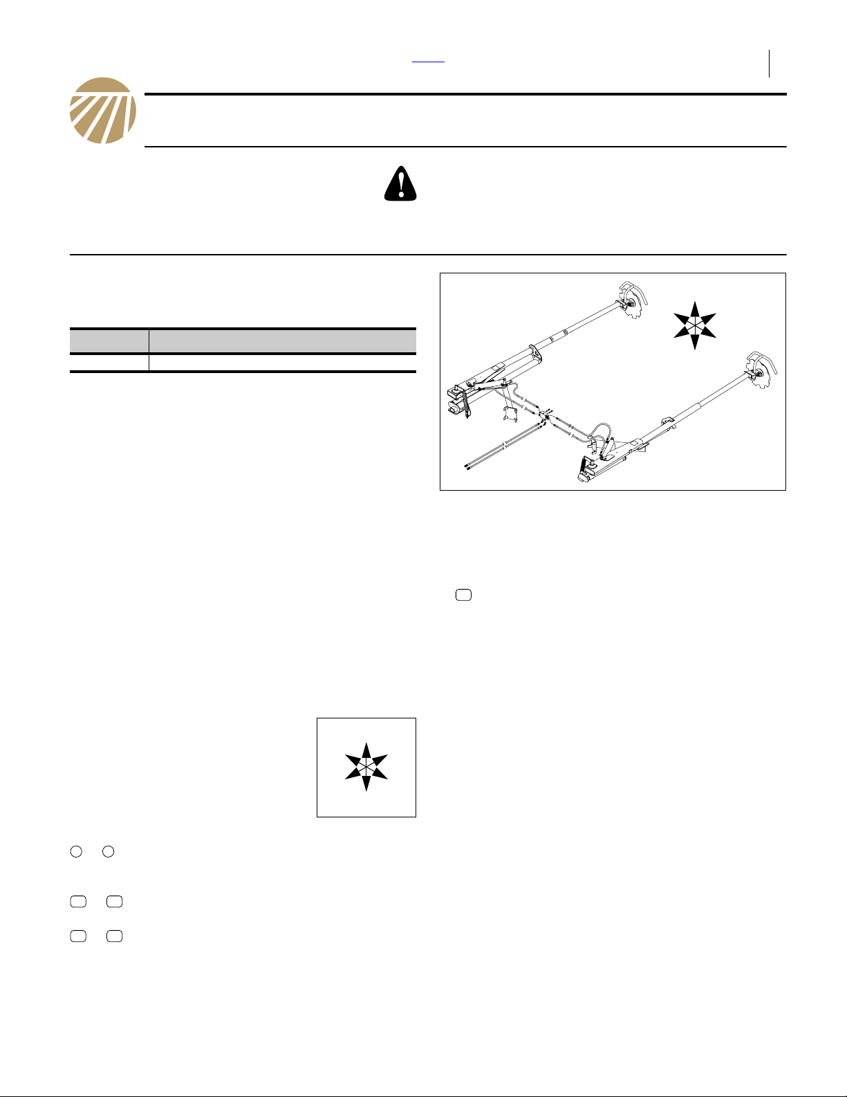
These instructions explain how to install field markers on
a compatible air drill implement.
These instructions apply to an installation of a 2013- kit:
warnings are serious - follow without exception.
Your life and the lives of others depend on it!
R
U
B
Kit Kit Description
113-849A NTA607HD-NTA2007HD MARKER BDL
Note: Kits manufactured in 2014 or later are described in
manual 113-921M. Compare Part List illustrations
if uncertain which manual applies to your kit.
One kit includes two markers (left and right), an automatic sequence valve, all hydraulic hoses and fittings,
and all necessary mounting hardware.
One kit updates one air drill.
Related Documents
Have the Operator Manual at hand for drill movements.
166-283M NTA607HD/2007HD Operator Manual
166-372M NTA607/2007 Operator Manual
166-372M-ENG NTA607 Operator Manual (EU)
Have the current Parts Manual at hand for parts ID.
166-283P NTA607HD/2007HD Parts Manual
166-372P NTA607/2007 Parts Manual
Notations and Conventions
“Left” and “Right” are facing in the
direction of machine travel. An orientation rose in the line art illustrations
shows the directions of Left, Right,
Front, Back, Up, Down.
Call-Outs
Single-digit callouts identify components in
1 9
to
11 12
to
21 80
to
Null4:
the currently referenced Figure or Figures.
These numbers may be reused for different
items from page to page.
Two-digit callouts in the range 11 to 12 reference affected existing parts (see page 18).
Two-digit callouts in the range 21 to 80 reference new parts (see list on page 18).
R
F
U
B
L
D
F
L
D
Null4:
Figure 1
Marker Kit
31327
Parts and Tools Required
• Locate two existing QD fittings supplied with the air
cart (see Figure 22 on page 21):
12
811-070C CP 3/4FORB QD
These fittings were bundled with the marker QD ports
on the rear of the air cart, but are typically removed
prior to delivery (they present an open line risk should
anyone activate the marker circuit prior to marker
installation).
• You need a suitable tractor for positioning the air drill,
and having sufficient hydraulic circuits, with adequate
capacity to operate the markers (installing markers
increases the required circuits to 3).
• You need a hoist with 136 kg (300 pound) capacity.
• Have safety goggles and gloves for inspecting hydraulic connections.
• Other than the hoist, only basic hand tools are
required.
• A few cable ties are required to secure hoses.
If orange colored ties are available, 6 can also be used
to identify hoses.
• 5 liters (1.2 gallons) of hydraulic fluid is needed to
charge the marker system.
Null4:
2013-10-10 ©Copyright 2010 113-850M
Page 2
2 2013- Single Fold Marker Front Parts Great Plains Mfg., Inc.
Before You Start
Compatibility
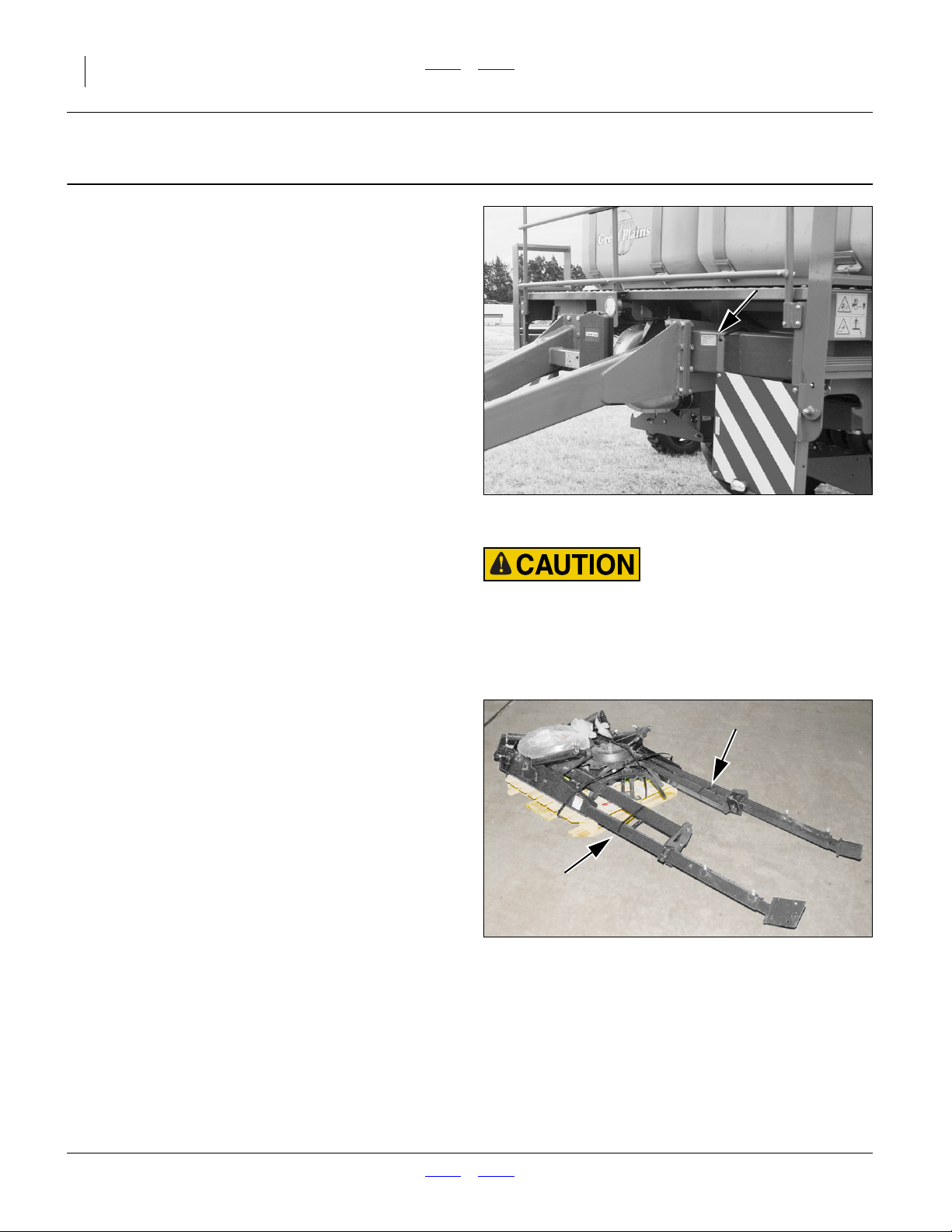
Refer to Figure 2
1. Check the model number of the air drill against the
list at the top of page 1 to ensure it is a compatible
model. For example, this kit is not compatible with
the NTA2000 integrated air drill (which uses a different marker kit).
Sequence
The mechanical installation may be performed on a disconnected implement, but testing of the system requires
the complete air drill.
If installing the markers as part of pre-delivery or export
final assembly, defer marker installation until after completing all items covered by manual 166-283Q.
Inventory
2. Make sure all parts are present.
Note: Delivered parts may be identified by Haukaas or
Great Plains part numbers. The Parts Lists beginning on page 18 show both numbers.
Note: Some parts are provided in left- and right-hand
versions with different part numbers. These are
not interchangeable and must be installed on the
implement side specified.
Null4:
Null4:
Null4:
Figure 2
NT607/2007HD Serial Number Plate
31174
Pinch / Crush Hazards:
Remove strapping only as instructed. The marker arms are
largely pre-assembled, and held closed by strapping. Premature removal creates pinch hazards and makes the assemblies
more hazardous to move and position.
Comprehension
3. Review these instructions. Make sure the installers
understand where each part or assembly is
installed, and what tools are required for the task.
Null4:
Null4:
Figure 3
Markers on Pallet
31361
113-850M Front Parts 2013-10-10
Page 3
Great Plains Mfg., Inc. Front Parts Installation Instructions 3
Pre-Assembly Preparation
Work Location
4. Move the air drill to a location with:
• room to fold it;
• access to tractor or hydraulic power;
• adequate illumination; and,
• clear surface beneath for recovery of any falling
or dropped parts - if the surface is not clear, have
a tarp or drop cloth available.
5. Raise drill. Unfold drill. Lower drill. This eases
access to the frames.
6. Set all hydraulic remote circuits to Float (to ensure
that pressure is relieved). Shut off tractor or hydraulic source.
Crushing Hazard:
Lower drill or support wing ends with gauge wheel lock channels. Although the center section may be held at raised by the
lift lock, unfolded wing ends slowly lower over time unless cylinder lock channels or external supports are used.
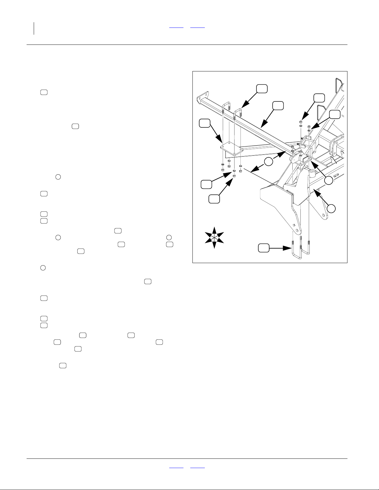
Install Arm Mechanisms
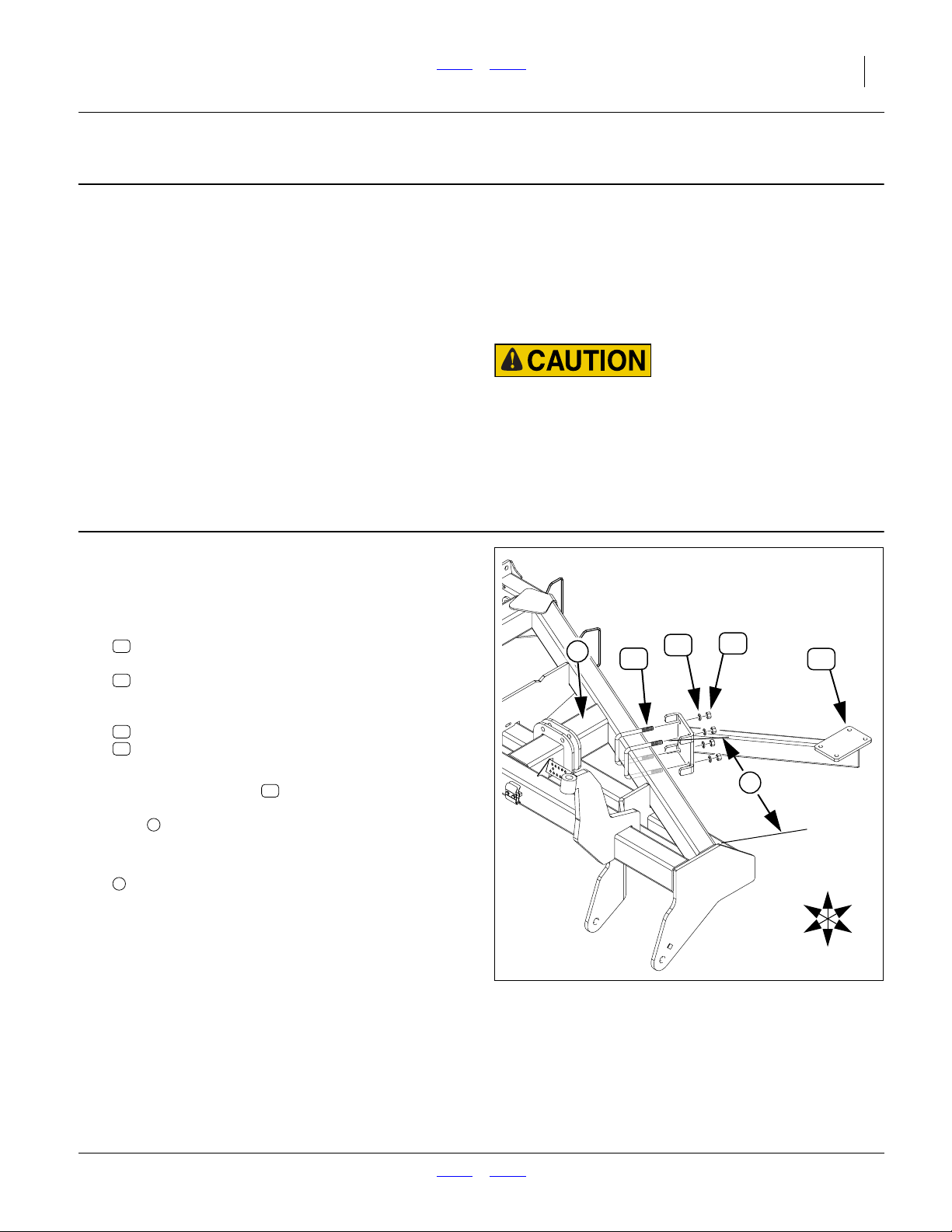
Install Arm Mounts
Install Left Mount
Refer to Figure 4
7. Select one new:
68
SFM-8670 Mounting Bracket Left SFM
two new:
22
FNS-024346 806-044C 5/8x5-1/16x5-1/2"
U-bolt U-BOLT 5/8-11 X 5 1/32 X 6
and four sets new:
38
FNS-56RPC 5/8"-11 NC Hex Nut
41
FNS-66RP 5/8" Split L/W YZ
8. With the arm to the rear, flat plate up, loosely install
the mounting bracket on the rear wing tool bar,
just outboard (left) of the wing cylinder mount
1
tube .
9. Adjust the initial position of the bracket for a distance:
2
74.0 cm (291⁄8 in.)
measured from the left outside face of a mount tab
to the left rear end of the rear tool bar (due to weld
fillets, this measurement is approximate).
Leave fasteners finger-tight until step 20.
Null4:
68
Null4:
1
41
22
38
68
2
U
R
F
B
L
D
Figure 4
Install Left Mount
31337
2013-10-10 Front Parts 113-850M
Page 4
4 2013- Single Fold Marker Front Parts Great Plains Mfg., Inc.
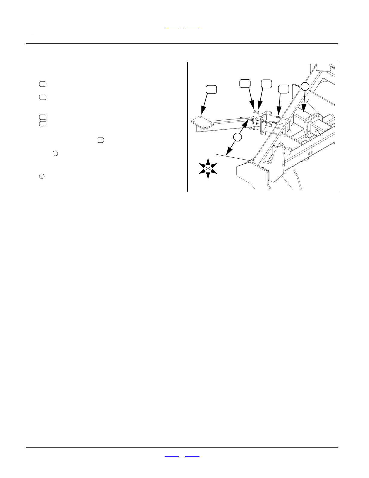
Install Right Mount
Refer to Figure 5
10. Select one new:
67
SFM-8669 Mounting Bracket Right SFM
two new:
22
FNS-024346 806-044C 5/8x5-1/16x5-1/2"
U-bolt U-BOLT 5/8-11 X 5 1/32 X 6
and four sets new:
38
FNS-56RPC 5/8"-11 NC Hex Nut
41
FNS-66RP 5/8" Split L/W YZ
11. With the arm to the rear, flat plate up, loosely install
the mounting bracket on the rear wing tool bar,
just outboard (right) of the wing cylinder mount
1
tube .
12. Adjust the initial position of the bracket for a distance:
3
74.9 cm (291⁄2 in.)
measured from the from right outside face of a
mount tab to the right rear end of the rear tool bar
(due to weld fillets, this measurement is approximate).
67
Null4:
B
R
67
U
L
F
D
38
41
3
Figure 5
Install Right Mount
22
1
31338
Leave fasteners finger-tight until step 28.
Null4:
113-850M Front Parts 2013-10-10
Page 5

Great Plains Mfg., Inc. Front Parts Installation Instructions 5
Install Arm Assemblies
Install Left Arm Assembly
Refer to Figure 6 (which, for clarity, depicts only the arm
subframe - what is installed is an entire arm assembly)
13. Select one new:
55
SFM-8657 Subframe Left - SFM
(which is an entire left arm assembly)
55
26
38
To reduce weight during installation, and reduce
arm length during system charge, remove the third
stage arm ( , not shown).
63
14. Leave in place any straps holding the arm in the
fully folded position. Remove only such straps as
are necessary to free the arm from the shipping
crate or pallet.
41
68
6
41
38
Secure the arm in a hoist, with the forward mounting
4
plate facing down.
15. Select two new:
23
FNS-02291 806-080C 5/8x4-1/16x6-1/2 Sq-
U-Bolt for 4x5 U-BOLT 5/8-11 X 4 1/32 X 6
and four sets new:
38
FNS-56RPC 5/8"-11 NC Hex Nut
41
FNS-66RP 5/8" Split L/W YZ
16. Position the arm assembly with the mounting
4 5
plate over the left end of the front tool bar .
Loosely secure with U-bolts , lock washers
and hex nuts .
38
55
23 41
17. Adjust the horizontal position to:
6
18.26 cm (73⁄16 in,)
measured from the outside face of the wing end
plate to the left side of the subframe tube.
55
18. Select two new:
26
FNS-02284
5/8-11x3-1/16x3-1/2 Sq-U-Bolt for3x2
and four sets new:
38
FNS-56RPC 5/8"-11 NC Hex Nut
41
FNS-66RP 5/8" Split L/W YZ
19. Using U-bolts , lock washers and hex
38 55
nuts , loosely secure the arm subframe to the
mount plate .
26 41
68
20. As necessary, adjust the final position of the
mount so that the arm subframe is parallel to the
68
wing end plate.
5
Null4:
Install Left Arm (Subframe Shown)
4
23
Figure 6
R
F
U
B
L
D
31339
Secure all fasteners to torque spec.
Null4:
2013-10-10 Front Parts 113-850M
Page 6
6 2013- Single Fold Marker Front Parts Great Plains Mfg., Inc.
Install Right Arm Assembly
Refer to Figure 7 (which, for clarity, depicts only the arm
subframe - what is installed is an entire arm assembly)
21. Select one new:
56
SFM-8658 Subframe Right SFM
(which is an entire right arm assembly)
26
38
56
To reduce weight during installation, and reduce
arm length during system charge, remove the third
stage arm ( , not shown).
63
22. Leave in place any straps holding the arm in the
fully folded position. Remove only such straps as
are necessary to free the arm from the shipping
crate or pallet.
67
41
3
Secure the arm in a hoist, with the forward mounting
1
plate facing down.
23. Select two new:
23
FNS-02291 806-080C 5/8x4-1/16x6-1/2 Sq-
U-Bolt for 4x5 U-BOLT 5/8-11 X 4 1/32 X 6
and four sets new:
38
FNS-56RPC 5/8"-11 NC Hex Nut
41
FNS-66RP 5/8" Split L/W YZ
24. Position the arm assembly with the mounting
1 2
plate over the right end of the front tool bar .
Loosely secure with U-bolts , lock washers
and hex nuts .
38
56
23 41
25. Adjust the horizontal position to:
3
19.84 cm (713⁄16 in,)
measured from the outside face of the wing end
plate to the right side of the subframe tube.
56
26. Select two new:
26
FNS-02284
5/8-11x3-1/16x3-1/2 Sq-U-Bolt for3x2
and four sets new:
38
FNS-56RPC 5/8"-11 NC Hex Nut
41
FNS-66RP 5/8" Split L/W YZ
27. Using U-bolts , lock washers and hex
38 56
nuts , loosely secure the arm subframe to the
mount plate .
26 41
67
28. As necessary, adjust the final position of the
mount so that the arm subframe is parallel to the
67
wing end plate.
Null4:
B
R
41
38
U
L
F
D
Install Right Arm (Subframe Shown)
23
Figure 7
1
2
31340
Secure all fasteners to torque spec.
Null4:
113-850M Front Parts 2013-10-10
Page 7
Great Plains Mfg., Inc. Front Parts Installation Instructions 7
Install Hydraulic Components
Before working with hydraulic components, review the
connector identification, torque specifications and sealant recommendations on page 15.
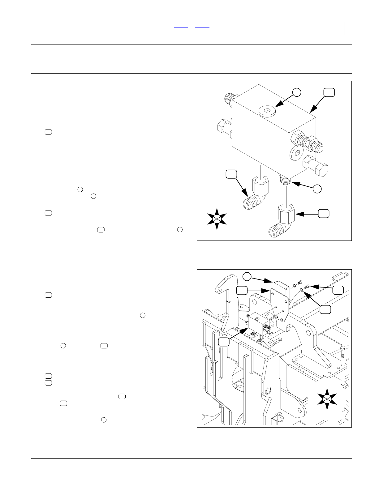
Prepare Sequence Valve
Refer to Figure 8
29. Select one new:
74
HYD-2480
SQV-SHOEMAKER #4129 (SIDE PORTS)
If the valve has elbows pre-installed, skip to step 32.
30. Examine the valve body to establish which faces are
front and top. The front face is blank except for
stamped text. The rear face has two3⁄8-16 threaded
holes (not shown). The top face has a single hex
socket plug . The bottom face has two MJIC/
MORB adaptors (the supply/return ports).
31. Select two new:
76
HYD-65000606
9/16 MJ - 9/16 FJS 90 DEG SWIVEL
32. Secure the elbows to the supply/return ports ,
with the MJIC ends of the elbows facing forward.
Null4:
4
5
76 5
R
F
Null4:
4
76
U
B
L
D
Figure 8
Prepare Sequence Valve
74
5
76
31343
Install Sequence Valve
Refer to Figure 9
33. On the implement center section, locate the:
11
160-762D WSMB MODULE MOUNT PLATE
It is pre-installed near the cart-implement hitch, and
has a DICKEY-john®WSMB-POM mounted. The
cables exiting the below the POM slightly interfere
with valve installation, so it is temporarily removed.
34. Remove and save the fasteners securing the
611
POM to the plate . Without disconnecting the
harness connections, carefully move the POM out
of the way.
35. Select two sets new:
70
FNS-120C5PC 3/8x3/4" UNC HCS GR5 YZ
71
FNS-62RP 3/8" Split L/W YZ
Mount the sequence valve on the front of the
11
plate , with the supply/return ports and elbows on
the bottom.
36. Re-secure the POM in its original location.
Null4:
74
6
6
Null4:
74
6
11
Figure 9
Mount Sequence Valve
R
F
70
71
U
B
L
D
31342
2013-10-10 Front Parts 113-850M
Page 8
8 2013- Single Fold Marker Front Parts Great Plains Mfg., Inc.
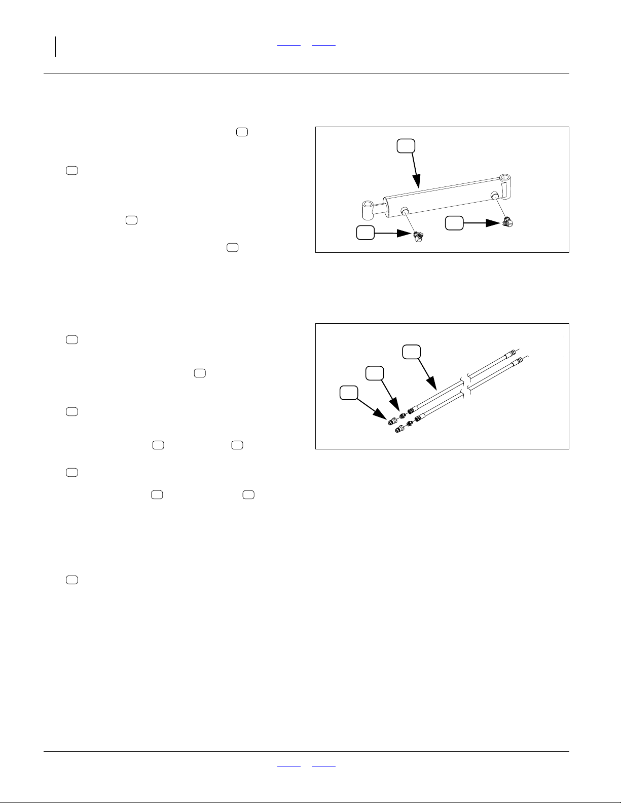
Install Cylinder Fittings
Refer to Figure 10
If elbows are pre-installed on the cylinders , skip to
step 38.
48
48
37. Select four new:
49
HYD-2787 #6ORBx9/16"JICM 90 6801-0606
Loosely install the MORB ends of the elbows at the
cylinder ports.
38. If the elbows were pre-installed, loosen the jam
nuts.
39. Adjust the orientation of the elbows so that the
MJIC inlets face up, and toward each other at
roughly a 45° angle. Tighten the jam nuts to ORB
49
49
Null4:
49
49
Figure 10
Cylinder Elbows
31344
torque spec.
Prepare Supply Hoses
Refer to Figure 11
40. Select two new:
72
HP-9JF100.375
3/8" HOSE X 100" 9/16 JICF ENDS
72
If the MORB-MJIC adaptors are already
75
installed on one end of each hose, skip to step 42.
41. Select two new:
75
HYD-6400680
ADAPTER 9/16 (#6) JICM - 3/4" (#8) ORB
Install one adaptor on each hose .
75 72
42. Select two existing:
12
811-070C CP 3/4FORB QD
Install one coupler on each adaptor .
12 75
43. If orange cable ties are available, secure one tie to
each hose end near the FJIC fitting. It is not necessary to separately identify one hose from the other.
Prepare Cylinder Hoses
44. Select two (of four):
73
HP-9JF154
3/8" HOSE X 154" 9/16 JICF ENDS
If orange ties are available, secure one tie to each
hose end near the FJIC fitting. If orange ties are not
available, use tape, tags or indelible marking pen to
identify hose ends or connectors as “R”. These are
the rod-end hoses.
Null4:
Null4:
12
75
Figure 11
Marker Supply/Return Hoses
31336
113-850M Front Parts 2013-10-10
Page 9

Great Plains Mfg., Inc. Front Parts Installation Instructions 9
Install Cylinder Hoses
Install Left Cylinder Hoses
8
7
4
3
5
Null4:
Left Cylinder Hose Routing
Refer to Figure 12 (a composite image)
45. Select two hoses:
73
HP-9JF154
3/8" HOSE X 154" 9/16 JICF ENDS
One with orange tie or “R” tag, and one without.
46. Connect one end of the hose with the orange/R
marking to sequence valve port R.
47. Connect the unmarked hose to sequence valve
port C
48. Route the hoses under the clamp on the rear
face of the wing lock lug. Leave clamps lightly snug
at this time, to allow for sag and slack adjustment at
step 52.
49. Route the hoses under the clamp at mid-wing
near the fold cylinder rod end.
50. Route the hoses to the front of the wing, under the
adjustment valve assembly and under the outer
wing clamp .
51. At the cylinder, connect the orange/R hose to the
elbow fitting at the rod end.
Connect the unmarked hose to the elbow at the
base end .
52. Adjust hose sag and slack per suggestions at right.
53. Tighten all clamps.
3
4
5
1
2
Figure 12
73
2
6
1
Left Sag and Slack:
• Allow just enough sag at the wing pivot so that the
hose is near, but no lower than the wing pivot pin .
• Where the hoses naturally cross each other at the
cylinder, secure a cable tie.
• Add a second tie approximately 40cm (16in) away, to
bundle the hoses.
• Create enough slack at this location for a loop no
higher than the eyebolt on the gauge wheel. The rod
end hose must follow the rod end of the cylinder as it
swings out and toward the rear during marker extension.
• Balance remaining slack at the adjustment valves and
at the sequence valve.
• Check that all slack is clear of moving parts.
C
R
31345
6
7
Null4:
2013-10-10 Front Parts 113-850M
Page 10

10 2013- Single Fold Marker Front Parts Great Plains Mfg., Inc.
Install Right Cylinder Hoses
Refer to Figure 13
54. Select two hoses:
73
HP-9JF154
3/8" HOSE X 154" 9/16 JICF ENDS
One with orange tie or “R” tag, and one without.
55. Connect one end of the hose with the orange/R
marking to sequence valve port R.
56. Connect the unmarked hose to sequence valve
port C
57. Route the hoses under the clamp on the rear
1
face of the wing lock lug. Leave clamps lightly snug
at this time, to allow for sag and slack adjustment at
step 61.
58. Route the hoses under the clamp at mid-wing
2
near the fold cylinder rod end.
59. Route the hoses to the front of the wing, under the
adjustment valve assembly and under the outer
wing clamp .
3
60. At the cylinder, connect the orange/R hose to the
elbow fitting at the rod end.
4
Connect the unmarked hose to the elbow at the
base end .
5
61. Adjust hose sag and slack:
• Allow just enough sag at the wing pivot so that
the hose is near, but no lower than the wing
pivot pin.
• Where the hoses naturally cross each other at
6
the cylinder, secure a cable tie.
• Add a second tie approximately 40cm (16in)
away, to bundle the hoses.
• Create enough slack at this location for a loop no
higher than the spring holder on the marker.
64
The rod end hose must follow the rod end of the
cylinder as it swings out and toward the rear during marker extension.
• Balance remaining slack at the adjustment valves
and at the sequence valve.
Check that all slack is clear of moving parts.
Null4:
64
3
73
R
1
Figure 13
Right Cylinder Hose Routing
6
4
5
2
C
31346
62. Tighten all clamps.
Null4:
113-850M Front Parts 2013-10-10
Page 11

Great Plains Mfg., Inc. Front Parts Installation Instructions 11
Install Supply Hoses
Refer to Figure 14
63. Select two new:
72
HP-9JF100.375
3/8" HOSE X 100" 9/16 JICF ENDS
As prepared at step 40 through step 43.
64. Connect the FJIC ends of the hoses to the MJIC
ports on the bottom of the sequence valve .
65. Route the hoses through the hose clamp
mounted upper the right side of the top hitch tool
bar. Leave clamps lightly snug at this time, to allow
for sag and slack adjustment at step 69.
Null4:
Refer to Figure 15
66. Route the left hose through the mid-hitch
clamp , which may have only one available clamping location.
67. Use a tie wrap to loosely secure the right hose to
the left hose near the mid clamp.
68. Route both hoses through the front clamp .
69. Adjust sag and slack:
• Allow enough slack near the sequence valve to
• allow most of the slack between the top and
• Allow only enough slack between the mid and
• Allow enough slack at the QD end of the hoses
Check that all slack is clear of moving parts.
70. Tighten all clamps.
Null4:
3
a
allow hose disconnection.
b
mid clamps. The distance between them
increases during lift.
c
front clamps to prevent hose kinking.
d
to allow easy disconnection. If the implement is
lowered during marker assembly, there will be
ample slack for the small change in distance from
the front clamp to the panel outlet during raise/
lower.
2
74
1
4
5
Null4:
Null4:
R
F
74
U
B
L
D
4
3
5
72
Figure 14
Valve to Hitch Hose Routing
b
2
c
d
Figure 15
Lower Hitch Hose Routing
1
31347
72
a
31348
2013-10-10 Front Parts 113-850M
Page 12

12 2013- Single Fold Marker Front Parts Great Plains Mfg., Inc.
Charge and Bleed System
Refer to Figure 16
71. Put on gloves and safety glasses.
72. Connect the QD ends of the marker supply
hoses to cart outlets A and B. Either hose may
be connected to either port.
73. Remove any strapping that holds the marker arms
closed.
Pinch / Crush / Striking Hazards:
Clear all objects from the sweep arcs of the marker arms.
Have all persons stand clear. The next steps fully deploy the
arms, and the motion may be sudden and irregular due to air
in the system.
74. Set the remote circuit assigned to the markers to
Neutral. Activate hydraulic power.
Note: Implement is still lowered. Normally, the imple-
75. While charging the system, bleed the markers per
the instructions in the 166-283M Operator Manual,
Maintenance topic.
76. Slowly move the marker circuit lever to Extend.
Observe which marker begins to move, and if neither, slowly reverse the lever to Retract.
77. Continuing slow operation, gradually extend a
marker arm on one side. When it reaches full extension, slowly reverse the lever and fold the marker.
When fully folded, set lever to Neutral.
78. Slowly reverse the lever. The other marker should
begin to deploy. Fully extend the marker, then fully
fold it.
79. Set circuit to Float and shut off hydraulic power.
Inspect the system for hydraulic leaks.
80. Repeat step 76 through step 78 two more times.
81. Perform another leak inspection.
82. Fold both markers. Set circuit to Neutral. Shut off
hydraulic power.
72
ment is raised for marker operations. With no third
stage arm or disk assembly installed, the markers
are short enough and light enough that they will
not strike the ground during initial exercising.
72
A
B
72
Null4:
Figure 16
Cart Hose Connections
High Pressure Fluid Hazard:
Escaping fluid under pressure can have sufficient pressure to
penetrate the skin causing serious injury. Avoid the hazard by
relieving pressure before disconnecting hydraulic lines. Use a
piece of paper or cardboard, NOT BODY PARTS, to check for
leaks. Wear protective gloves and safety glasses or goggles
when working with hydraulic systems. If an accident occurs,
seek immediate medical assistance from a physician familiar
with this type of injury.
31349
Null4:
113-850M Front Parts 2013-10-10
Page 13

Great Plains Mfg., Inc. Front Parts Installation Instructions 13
Install Marker Disk and Guard
Install Third Stage Arm
Start with the left marker.
Refer to Figure 17
83. If pre-installed, loosen the jam nuts and set
screws in the second stage arm .
45 62
37
1
If not pre-installed, select two sets new:
37
FNS-54JPC 1/2"- 13 NC Jam Nut
45
FNS-8A41BPC 1/2 x1-1/2"SQ HD SET YZ
Place a jam nut on a set screw . Screw this
37 45
assembly a few turns into the threaded holes on the
outer end of the arm .
62
84. Select one new:
63
SFM-8665 Third Stage Arm SFM
Orient the disk mounting lug so that it is angled in
1
(toward implement center with markers folded).
Insert the third stage arm fully into the second
stage arm .
62
63
85. Tighten the set screws to1⁄2 turn beyond finger
tight. (The initial marker extension is set at step 96.)
86. Repeat step 83 through step 85 for the right side.
The lug is angled in on the right side as well.
Install Bearing Assembly and Guard
Start with the left marker.
Refer to Figure 18
87. Select one each new:
53
SA-9041 Disc Assy Complete w/o DISC/GAUGE
54
SFM-8223 Disc Guard
and two sets new:
34
FNS-241C5PC 1/2x1-3/4"" Carriage Bolt 5 YZ
43
FNS-74RP 1/2" Flat Washer
47
FNS-94SLN 1/2" Stover Nut UNC YZ
Loosely mount the bearing assembly under the
arm lug , and the guard on top of the lug, bent
63 54
tube facing to implement rear (with arm folded).
Figure 18 shows the carriage bolt in the inside
small slotted hole for a left arm installation. This
2
provides maximum angles for throwing dirt inward in
operation. This is a user preference issue.
88. Repeat step 87 and step 87 for the right side. Use
the alternate small slotted hole.
53
34
Null4:
53
63
34
3762
45
Figure 17
Install Third Stage Arm
47
43
54
52
2
63
31350
39
39
Null4:
Figure 18
31351
Install Bearing Assembly
2013-10-10 Front Parts 113-850M
Page 14

14 2013- Single Fold Marker Front Parts Great Plains Mfg., Inc.
Install Disc and Depth Gauge
Start with the left marker.
Sharp Object Hazard:
Wear gloves and be cautious when working with marker discs.
The edges are sharp.
Refer to Figure 19
89. Select one each new
44
FNS-79NP 1" Flat Washer
50
MIS-2192 Nylon Depth Guage
52
MIS-2526 18" Notched Blade
39
FNS-59JPC 1" - 8 Jam Nut PLT
54
39
39
Place the disc blade on the disc axle .
52 79
The disc is shown concave side toward arm, but it
may be mounted concave side out per user preference.
Add the depth gauge , rim side toward arm, the
flat washer and a jam nut . Avoid crushing the
44 39
50
nylon depth gauge when tightening the first (inner)
jam nut.
90. Select one each new
42
FNS-69RP 1" Split L/W YZ
39
FNS-59JPC 1" - 8 Jam Nut PLT
Add the lock washer and the second jam nut
42 39
to the axle. Tighten the second jam nut, against the
first, to Class 5.8 (Grade 2) torque specification.
91. Adjust the bearing assembly for the desired disc
53
angle of throw.
92. Adjust the guard so that the double-end tube is
aligned with the disc edge.
93. Secure the bearing/guard fasteners to torque spec.
94. Repeat step 89 through step 93 for the right marker.
Set Initial Extension and Tension
Null4:
53
79
Figure 19
Install Disc & Depth Gauge
52
44
50
42
31352
95. With the implement still lowered, extend a marker
on one side. At full retraction, it should remain suspended above the ground. Set the circuit to Neutral
and shut off hydraulics.
96. Set the approximate initial marker extension per the
instructions in the 166-283M Operator manual.
Because the implement is typically not into the
ground at this time, the setting is approximate.
97. Set the initial marker tension to 23 kg (50 lbs.) per
the instructions in the 166-283M Operator manual.
Null4:
113-850M Front Parts 2013-10-10
Page 15

Great Plains Mfg., Inc. Front Parts Installation Instructions 15
Close-Out
98. Fold the markers.
99. Raise the implement.
100. Fold the implement.
101. Lower the implement into lift lock.
Appendix
Hydraulic Connector Identification
Refer to Figure 20 (a hypothetical fitting)
Leave any protective caps in place until immediately prior
to making a connection.
1
NPT - National Pipe Thread
Note tapered threads, no cone/flare, and no O-ring.
Apply liquid pipe sealant for hydraulic applications
(do not use tape sealant, which can foul filters).
2
JIC - Joint Industry Conference (SAE J514)
Note straight threads and the 37° cone on
“M” fittings (or 37° flare on “F” fittings). Use no
sealants (tape or liquid) on JIC fittings.
3
ORB - O-Ring Boss (SAE J514)
Note straight threads and elastomer O-Ring .
Prior to installation, to prevent abrasion during tightening, lubricate O-Ring with clean hydraulic fluid.
Use no sealants (tape or liquid) on JIC fittings.
ORB fittings that need orientation, such as the ell
depicted, also have a washer and jam nut
(“adjustable thread port stud”). Back jam nut away
from washer. Thread fitting into receptacle until
O-Ring contacts seat. Unscrew fitting to desired
orientation. Tighten jam nut to torque specification.
4 5
5 7
8 9
Marker Operation
Marker operation is covered thoroughly in the 166-283M
Operator manual.
Marker Maintenance
Marker maintenance is covered thoroughly in the166283M Operator manual.
1
9
8
4
5
2
Null4:
Hydraulic Connector ID
Null4:
Null4:
Fittings Torque Values
Fitting Ft-Lbs N-m
1
⁄4 NPT 1.5-3.0 turns past finger tight
9
⁄16 JIC 18-20 24-27
9
⁄16 ORB w/jam nut 12-16 16-22
9
⁄16 ORB straight 18-24 24-32
3
⁄4 JIC 27-39 37-53
3
⁄4 ORB w/jam nut 20-30 27-41
3
⁄4 ORB straight 27-43 37-58
Figure 20
7
5
3
31282
Null4:
2013-10-10 Front Parts 113-850M
Page 16

16 2013- Single Fold Marker Front Parts Great Plains Mfg., Inc.
Torque Chart
8.5 13 18
15 24 33
17 26 37
27 42 59
31 47 67
43 67 95
49 75 105
66 105 145
75 115 165
95 150 210
105 165 235
130 205 285
150 230 325
235 360 510
260 405 570
225 585 820
250 640 905
340 875 1230
370 955 1350
480 1080 1750
540 1210 1960
680 1520 2460
750 1680 2730
890 1990 3230
1010 2270 3680
1180 2640 4290
1330 2970 4820
61014 5 811
11 17 25 12 19 27
13 19 27 13 21 29
20 31 44 24 39 53
22 35 49 29 45 62
32 49 70 42 67 93
36 55 78 44 70 97
49 76 105 66 77 105
55 85 120 68 105 150
70 110 155 73 115 160
79 120 170 105 165 230
97 150 210 115 180 245
110 170 240 145 230 300
170 265 375 165 260 355
190 295 420 205 325 450
165 430 605 230 480 665
185 475 670 355 560 780
250 645 910 390 610 845
275 705 995 705 1120 1550
355 795 1290 785 1240 1710
395 890 1440 1270 1950 2700
500 1120 1820 1380 2190 3220
555 1240 2010
655 1470 2380
745 1670 2710
870 1950 3160
980 2190 3560
M 6 X 1
M 8 X 1.25
M 8 X 1
M10 X 1.5
M10 X 0.75
M12 X 1.75
M12 X 1.5
M12 X 1
M14 X 2
M14 X 1.5
M16 X 2
M16 X 1.5
M18 X 2.5
M18 X 1.5
M20 X 2.5
M20 X 1.5
M24 X 3
M24 X 2
M30 X 3.5
M30 X 2
M36 X 3.5
M36 X 2
a. in-tpi = nominal thread diameter in inches-threads per inch
b. N· m = newton-meters
c. mm x pitch = nominal thread diameter in mm x thread pitch
d. ft-lb = foot pounds
71115
17 26 36
18 28 39
33 52 72
39 61 85
58 91 125
60 95 130
90 105 145
92 145 200
99 155 215
145 225 315
155 240 335
195 310 405
220 350 485
280 440 610
310 650 900
480 760 1050
525 830 1150
960 1510 2100
1060 1680 2320
1730 2650 3660
1880 2960 4100
+ 0%, -15% of torquing values. Unless otherwise specified use torque values listed above.
Null4:
113-850M Front Parts 2013-10-10
25199m
25199
Page 17

Great Plains Mfg., Inc. Front Parts Installation Instructions 17
Parts Lists
39
47
43
42
59
44
68
47
54
B
R
58
43
U
D
51
L
F
55
38
41
22
67
26
49
41
46
33
44
48
27
38
38
41
51
38
33
56
63
Null4:
39
61
35
50
28
35
31
52
33
37
25
47
53
51
34
45
47
62
29
}
40
36
Figure 21
Marker Kit Mechanical Components
43
38
32
47
66
38
57
38
60
23
64
47
69
30
31333
2013-10-10 Front Parts 113-850M
Page 18

18 2013- Single Fold Marker Front Parts Great Plains Mfg., Inc.
Existing Parts
The part call-out numbers in this list match all Figures in
these installation instructions. Part descriptions match
those in your updated Parts Manual.
The Part Disposition column indicates whether the part is
re-used or discarded.
Figure 22
Callout
11 1
12 2
a This part is pre-installed on the implement and left in place.
b This coupler is supplied with the NTA607HD or NTA2007HD air cart.
Quantity
Required
a
b
Great Plains
Part Number
160-762D WSMB MODULE MOUNT PLATE
811-070C CP 3/4FORB QD
New Parts
113-849A Kit Contents
Great Plains part numbers and descriptions are listed
above Haukaas equivalents. For replacements, order the
Great Plains part numbers.
Quantities are units (“ea”).
Figure 21
Callout
21 1
22 4
23 4
24 1
Quantity
in Kit
Haukaas Part No.
GP Part Number
-
113-850M
FNS-024346
806-044C
FNS-02291
806-080C
9269
828-064C
Great Plains Part Description
Haukass Part Description
MANUAL 20FT SWING-ARM MARKER
5/8x5-1/16x5-1/2" U-bolt
U-BOLT 5/8-11 X 5 1/32 X 6
5/8x4-1/16x6-1/2 Sq-U-Bolt for 4x5
U-BOLT 5/8-11 X 4 1/32 X 6
Great Plains Single Fold Markers
HAUKAAS MARKER (NTA607HD)
Great Plains Part Description
The part call-out numbers in this list match all Figures in
these installation instructions. Part descriptions match
those in your updated Parts Manual.
9269 828-064C (9269 828-064C) Bundle Contents
Haukaas part numbers and descriptions are listed first.
New parts in the kit show these identifications.
Figure 21
Callout
25 4
26 4
27 2
28 2
29 16
30 2
31 2
113-850M Front Parts 2013-10-10
Quantity
in Kit
Haukaas Part No.
GP Part Number
BRG-2450
BRG-2450
FNS-02284
806-157C
FNS-02392
FNS-02392
FNS-124-5PC
802-223C
FNS-131B5PC
802-029C
FNS-142B5PC
802-130C
FNS-143C8PC
802-853C
Haukass Part Description
Great Plains Part Description
1-1/4"- Bearing &Housing Assembly (4 Blt)
HAUKAAS 1-1/4 BRG & HSNG COMP
5/8-11x3-1/16x3-1/2 Sq-U-Bolt for3x2
U-BOLT 5/8-11 X 3 1/32 X 3 1/2
5/8-11x6" I-BOLT (4" THREAD) #104
HAUKAS 5/8-11X6 I-BLT(4"THREAD
3/8x4" UNC HCS GR5 YZ
HHCS 3/8-16X4 GR5
7/16x1-1/2" UNC HCS GR5 YZ
HHCS 7/16-14X1 1/2 GR5
1/2 X 2-1/2"" HCS GR 5 YZ
HHCS 1/2-13X2 1/2 GR5
1/2 x 3-3/4" NC 8PL
HHCS 1/2-13X3 3/4 GR8
For replacements, order the Great Plains part numbers
(if different) shown below the Haukaas numbers.
Page 19

Great Plains Mfg., Inc. Front Parts Installation Instructions 19
Figure 21
Callout
32 2
33 6
34 2
35 12
36 16
37 4
38 2
39 4
40 16
41 48
42 2
43 16
44 4
45 4
46 6
47 12
48 2
49 4
50 2
51 4
52 2
53 2
54 2
Quantity
in Kit
a
a
Haukaas Part No.
GP Part Number
FNS-163-5PC
802-059C
FNS-241B5PC
802-106C
FNS-241C5PC
802-331C
FNS-52RPC
803-014C
FNS-53RPC
803-015C
FNS-54JPC
803-036C
FNS-56RPC
803-021C
FNS-59JPC
803-030C
FNS-63RP
804-014C
FNS-66RP
804-022C
FNS-69RP
804-027C
FNS-74RP
804-113C
FNS-79NP
804-029C
FNS-8A41BPC
801-013C
FNS-8CB-1BP
805-104C
FNS-94SLN
803-342C
HYD-236801
HYD-236801
HYD-2787
811-065C
MIS-2192
MIS-2192
MIS-2325
800-001C
MIS-2526
MIS-2526
SA-9041
SA-9041
SFM-8223
SFM-8223
Haukass Part Description
Great Plains Part Description
5/8 X 3"" UNC HCS GR5 YZ
HHCS 5/8-11X3 GR5
1/2x1-1/2" Carriage Bolt 5P
RHSNB 1/2-13X1 1/2 GR5
1/2x1-3/4"" Carriage Bolt 5 YZ
RHSNB 1/2-13X1 3/4 GR5
3/8" NC Hex Nut
NUT HEX 3/8-16 PLT
7/16"- 14 NC Hex Nut
NUT HEX 7/16-14 PLT
1/2"- 13 NC Jam Nut
NUT HEX JAM 1/2-13 PLT
5/8"-11 NC Hex Nut
NUT HEX 5/8-11 PLT
1" - 8 Jam Nut PLT
NUT HEX JAM 1-8 PLT
7/16" Split L/W PLT
WASHER LOCK 7/16 PLT
5/8" Split L/W YZ
WASHER LOCK SPRING 5/8 PLT
1" Split L/W YZ
WASHER LOCK SPRING 1 PLT
1/2" Flat Washer
WASHER FLAT 1/2 USS HARD PLT
1" Flat Washer
WASHER FLAT 1 SAE
1/2 x1-1/2"SQ HD SET YZ
SCREW SET SQ HD 1/2-13X1 1/2G5
3/16 x 1-1/2 Cotter-Pin
PIN COTTER 3/16 X 1 1/2 PLT
1/2" Stover Nut UNC YZ
NUT HEX TOP LOCK 1/2-13 PLT
Cylinder,Hyd 2-1/2 x 12 PAL 1200132
HAUKAAS CYL 2-1/2X12PAL1200132
#6ORBx9/16"JICM 90 6801-0606
EL 9/16MJIC 9/16MORB
Nylon Depth Guage
HAUKAAS NYLON DEPTH GAUGE
.250 Grease Zirk (GF641)
GREASE ZERK STRAIGHT 1/4-28
18" Notched Blade
HAUKAAS 18" NOTCHED DISC BLADE
Disc Assy Complete w/o DISC/GAUGE
HAUKAS DISC ASY W/O DISC/GAGE
Disc Guard
HAUKAAS DISC GUARD
2013-10-10 Front Parts 113-850M
Page 20

20 2013- Single Fold Marker Front Parts Great Plains Mfg., Inc.
Figure 21
Callout
55 1
56 1
57 1
58 1
59 1
60 1
61 2
62 2
63 2
64 2
65 2
66 2
67 1
68 1
69 2
a Some of this count is found in subordinate kits.
Quantity
in Kit
Haukaas Part No.
GP Part Number
SFM-8657
SFM-8657
SFM-8658
SFM-8658
SFM-8659
SFM-8659
SFM-8660
SFM-8660
SFM-8661
SFM-8661
SFM-8662
SFM-8662
SFM-8663
SFM-8663
SFM-8664
SFM-8664
SFM-8665
SFM-8665
SFM-8666
SFM-8666
SFM-8667
SFM-8667
SFM-8668
SFM-8668
SFM-8669
SFM-8669
SFM-8670
SFM-8670
SPR-2395
SPR-2395
Haukass Part Description
Great Plains Part Description
Subframe Left - SFM
HAUKAAS SUBFRAME LEFT SFM
Subframe Right SFM
HAUKAAS SUBFRAME RIGHT SFM
End Bushing Right SFM
HAUKAAS END BUSHING RIGHT SFM
End Bushing Left SFM
HAUKAAS END BUSHING LEFT SFM
Pivot Frame Left SFM
HAUKAAS PIVOT FRAME LEFT SFM
Pivot Frame Right SFM
HAUKAAS PIVOT FRAME RIGHT SFM
Primary Arm SFM
HAUKAAS PRIMARY ARM SFM
Second Stage Arm SFM
HAUKAAS SECOND STAGE ARM SFM
Third Stage Arm SFM
HAUKAAS THIRD STAGE ARM SFM
Spring Holder SFM
HAUKAAS SPRING HOLDER SFM
Arm Rest SFM
HAUKAAS ARM REST SFM
Cylinder Pin SFM
HAUKAAS CYLINDER PIN SFM
Mounting Bracket Right SFM
HAUKAAS MOUNTING BRACKET RIGHT
Mounting Bracket Left SFM
HAUKAAS MOUNTING BRACKET LEFT
DSA/MED/CB Spring 02-200934-1
HAUKAAS MEDIUM CB SPRING
Null4:
113-850M Front Parts 2013-10-10
Page 21

Great Plains Mfg., Inc. Front Parts Installation Instructions 21
9269 Hydraulic Package Contents
Unless the part has only a Great Plains part number,
Haukaas part numbers and descriptions are listed first.
New parts in the kit show these identifications.
For replacements, order the Great Plains part numbers
(if different) shown below the Haukaas numbers.
49
49
73
71
70
73
73
75
12
74
76
Null4:
Figure 22
Callout
12
49
70 2
71 10
72 2
73 4
74 1
75 2
76 2
a Some of this count is found in the SA-9041 bundle (page 19).
Quantity
in Kit
See
page 18
See
page 19
a
Haukaas Part No.
GP Part Number
-
811-070C
HYD-2787
811-065C
FNS-120C5PC
802-014C
FNS-62RP
804-013C
HP-9JF100.375
HP-9JF100.375
HP-9JF154
HP-9JF154
HYD-2480
HYD-2480
HYD-6400680
811-133C
HYD-65000606
811-169C
72
Null4:
Figure 22
Haukaas Hydraulic Package
Haukass Part Description
Great Plains Part Description
CP 3/4FORB QD
#6ORBx9/16"JICM 90 6801-0606
EL 9/16MJIC 9/16MORB
3/8x3/4" UNC HCS GR5 YZ
HHCS 3/8-16X3/4 GR5
3/8" Split L/W YZ
WASHER LOCK SPRING 3/8 PLT
3/8" HOSE X 100" 9/16 JICF ENDS
3/8" HOSE X 100" 9/16 JICF ENDS
3/8" HOSE X 154" 9/16 JICF ENDS
3/8 HYD HOSE X 154 9/16FJIC
SQV-SHOEMAKER #4129 (SIDE PORTS)
HAUKAAS SQV-SHOEMAKER #4129
ADAPTER 9/16 (#6) JICM - 3/4" (#8) ORB
AD 9/16MJIC 3/4MORB
9/16 MJ - 9/16 FJS 90 DEG SWIVEL
EL 9/16MJIC 9/16FJIC
73
49
49
31336
2013-10-10 Front Parts 113-850M
Page 22

22 2013- Single Fold Marker Front Parts Great Plains Mfg., Inc.
SA-9041 Disc Assembly Contents
Haukaas part numbers and descriptions are listed first.
New parts in the kit show these identifications.
For replacements, order the Great Plains part numbers
(if different) shown below the Haukaas numbers.
79
Null4:
Figure 23
Callout
35
46
71
77 8
78 2
79 2
80 4
Quantity
in Kit
See
page 19
See
page 19
See
page 21
Haukaas Part No.
GP Part Number
FNS-52RPC
803-014C
FNS-8CB-1BP
FNS-8CB-1BP
FNS-62RP
804-013C
FNS-221B5PC
802-453C
SA-8056
SA-8056
SA-8084
SA-8084
BRG-2476
BRG-2476
77
71
80
Null4:
Haukaas Disc Assembly
Haukass Part Description
Great Plains Part Description
3/8" NC Hex Nut
NUT HEX 3/8-16 PLT
3/16 x 1-1/2 Cotter-Pin
3/16 x 1-1/2 Cotter-Pin
3/8" Split L/W YZ
WASHER LOCK SPRING 3/8 PLT
3/8x1-1/2" Carriage Bolt 5 PL
RHSNB 3/8-16X1 1/2 GR5
Disc Assembly Bracket
HAUKAAS DISC ASSEMBLY BRACKET
Disc Axle
HAUKAAS DISC AXLE
1" Bearing & Housing Assembly (2 Blt)
HAUKAAS 1" BRG & HSG COMP 2BLT
Figure 23
35
{
46
78
31334
113-850M Front Parts 2013-10-10
Page 23

Great Plains Mfg., Inc. Front Parts Installation Instructions 23
Abbreviations
AD Adaptor L/W Lock Washer
BLT Bolt MED Medium
BRG Bearing MIS Miscellaneous
CB Counter-Balance MJ MJIC
COMP Complete MJIC Male JIC
CYL Cylinder MORB Male ORB
DEG Degree NC National Coarse
EL Elbow NTA No-Till Air
FJS Female JIC Swivel ORB O-Ring Boss
FNS Fastener PLT Plated
FORB Female ORB QD Quick Disconnect
FT Foot RHSNB Round Head Shank Neck Bolt
GR5 Grade 5 SA Stabilizer Arm
HCS Hex Cap Screw SAE Society of Automotive Engineers (standard)
HD Head SFM Single Fold Marker
HEX Hexagonal SPR Spring
HHCS Hex Head Cap Screw SQ Square
HSNG Housing SQV Sequence Valve
HYD Hydraulic UNC Unified National Coarse
IN Inch USS United States Standard (heavy duty)
JIC Joint Industry Conference (standard) W/O Without
JICF JIC Female X by
JICM JIC Male YZ Yellow Zinc plated
Null4:
2013-10-10 Front Parts 113-850M
Page 24

24 2013- Single Fold Marker Front Parts Great Plains Mfg., Inc.
EOD
Great Plains Manufacturing, Inc.
Corporate Office P.O. Box 5060
Salina, Kansas 67402-5060 USA
113-850M Front Parts 2013-10-10
 Loading...