

Page 1
Operator’s Manual
NTA 1000 and NTA 1300
Manufacturing, Inc.
www.greatplainsmfg.com
Read the operator’s manual entirely. When you see this symbol, the subsequent in-
!
structions and warnings are serious - follow without exception. Your life and the lives of
others depend on it!
© Copyright 2000 Printed
6/30/2005
19354
Cover illustration may show optional equipment not supplied with standard unit.
148-528M
Page 2

Table of Contents
Great Plains Mfg., Inc.
Table of Contents
Important Safety Information . . . . . . . . . . . . . . . . . 1
Safety Decals. . . . . . . . . . . . . . . . . . . . . . . . . . . . 4
Introduction . . . . . . . . . . . . . . . . . . . . . . . . . . . . . . . 8
Description of Unit . . . . . . . . . . . . . . . . . . . . . . . . 8
Using This Manual. . . . . . . . . . . . . . . . . . . . . . . . 8
Definitions . . . . . . . . . . . . . . . . . . . . . . . . . . . 8
Owner Assistance . . . . . . . . . . . . . . . . . . . . . . . . 8
Preparation and Set-Up . . . . . . . . . . . . . . . . . . . . . . 9
Prestart Checklist . . . . . . . . . . . . . . . . . . . . . . . . 9
Wiring Drill . . . . . . . . . . . . . . . . . . . . . . . . . . . . . . . 9
Hitching Tractor to Implement . . . . . . . . . . . . . . 10
Hydraulic Hook-up . . . . . . . . . . . . . . . . . . . . . . . 11
Bleeding Hydraulic Systems . . . . . . . . . . . . . . . 12
Operating Instructions. . . . . . . . . . . . . . . . . . . . . . 14
Prestart Checklist . . . . . . . . . . . . . . . . . . . . . . . 14
Field Operation . . . . . . . . . . . . . . . . . . . . . . . . . 14
Opener Operation . . . . . . . . . . . . . . . . . . . . 15
Pivot Lock Tubes . . . . . . . . . . . . . . . . . . . . . 15
Marker Operation . . . . . . . . . . . . . . . . . . . . 15
Fan Operation . . . . . . . . . . . . . . . . . . . . . . . 15
Transport Lift Cylinders . . . . . . . . . . . . . . . . 15
Transporting. . . . . . . . . . . . . . . . . . . . . . . . . . . . 16
Folding the Drill . . . . . . . . . . . . . . . . . . . . . . . . . 17
Unfolding the Drill . . . . . . . . . . . . . . . . . . . . . . . 19
Parking . . . . . . . . . . . . . . . . . . . . . . . . . . . . . . . 19
Adjustments . . . . . . . . . . . . . . . . . . . . . . . . . . . . . . 20
Seeding Depth. . . . . . . . . . . . . . . . . . . . . . . . . . 20
Coulters. . . . . . . . . . . . . . . . . . . . . . . . . . . . 20
Openers . . . . . . . . . . . . . . . . . . . . . . . . . . . 20
Coulter Depth . . . . . . . . . . . . . . . . . . . . . . . . . . . 21
Hydraulic Control . . . . . . . . . . . . . . . . . . . . . 21
Coulter Mounting Height . . . . . . . . . . . . . . . 22
Coulter Down Pressure . . . . . . . . . . . . . . . . . . . 22
Added Weight. . . . . . . . . . . . . . . . . . . . . . . . 22
Coulter Springs . . . . . . . . . . . . . . . . . . . . . . 22
Opener Depth. . . . . . . . . . . . . . . . . . . . . . . . . . . 23
Press Wheel Adjustment . . . . . . . . . . . . . . . 23
Opener Mounting Height . . . . . . . . . . . . . . . 23
Opener Down Pressure . . . . . . . . . . . . . . . . . . . 24
Disk Scraper Adjustment . . . . . . . . . . . . . . . . . . 24
Harrow Adjustment. . . . . . . . . . . . . . . . . . . . . . . 25
Leaf Spring Adjustment . . . . . . . . . . . . . . . . . . . 25
Marker Adjustments . . . . . . . . . . . . . . . . . . . . . . 26
Disk Adjustments . . . . . . . . . . . . . . . . . . . . . 26
Pivot Lock Tube Adjustment . . . . . . . . . . . . . . . . 27
Seed-Lok Lock Up . . . . . . . . . . . . . . . . . . . . . . . 27
Troubleshooting . . . . . . . . . . . . . . . . . . . . . . . . . . . 28
Maintenance and Lubrication . . . . . . . . . . . . . . . . 30
Maintenance. . . . . . . . . . . . . . . . . . . . . . . . . . . . 30
Transport Cylinder Support Brace . . . . . . . . 31
Storage. . . . . . . . . . . . . . . . . . . . . . . . . . . . . . . . 31
Lubrication . . . . . . . . . . . . . . . . . . . . . . . . . . . . . 32
Options . . . . . . . . . . . . . . . . . . . . . . . . . . . . . . . . . . 35
Specifications and Capacities . . . . . . . . . . . . . . . . 36
Appendix . . . . . . . . . . . . . . . . . . . . . . . . . . . . . . . . . 37
Tire Inflation Chart . . . . . . . . . . . . . . . . . . . . . . . 37
Torque Values Chart for Common Bolt Sizes . . . 37
Warranty. . . . . . . . . . . . . . . . . . . . . . . . . . . . . . . 38
© Copyright 2000 All rights Reserved
Great Plains Manufacturing, Inc. provides this publication “as is” without warranty of any kind, either expressed or implied. While every precaution has been taken in the preparation
of this manual, Great Plains Manufacturing, Inc. assumes no responsibility for errors or omissions. Neither is any liability assumed for damages resulting from the use of the information contained herein. Great Plains Manufacturing, Inc. reserves the right to revise and improve its products as it sees fit. This publication describes the state of this product at the
time of its publication, and may not reflect the product in the future.
The following are trademarks of Great Plains Mfg., Inc.: Application Systems, Ausherman, Land Pride, Great Plains, Seed-Lok
All other brands and product names are trademarks or registered trademarks of their respective holders.
NTA 1000 and NTA 1300 148-528M 5/26/2006
Great Plains Manufacturing, Incorporated Trademarks
Printed in the United States of America.
Page 3

Great Plains Mfg., Inc.
Important Safety Information
Important Safety Information
Look for Safety Symbol
The SAFETY ALERT SYMBOL indicates there is a potential hazard to
personal safety involved and extra
safety precaution must be taken.
When you see this symbol, be alert
and carefully read the message that
follows it. In addition to design and
configuration of equipment, hazard
control and accident prevention are
dependent upon the awareness, concern, prudence and proper training of
personnel involved in the operation,
transport, maintenance and storage
of equipment.
!
Be Aware of Signal Words
Signal words designate a degree or
level of hazard seriousness. The signal words are:
!
DANGER!
Indicates an imminently hazardous
situation which, if not avoided, will
result in death or serious injury. This
signal word is limited to the most
extreme situations, typically for
machine components that, for functional purposes, cannot be guarded.
!
WARNING!
Indicates a potentially hazardous situation which, if not avoided, could
result in death or serious injury, and
includes hazards that are exposed
when guards are removed. It may
also be used to alert against unsafe
practices.
!
CAUTION!
Indicates a potentially hazardous situation which, if not avoided, may
result in minor or moderate injury. It
may also be used to alert against
unsafe practices.
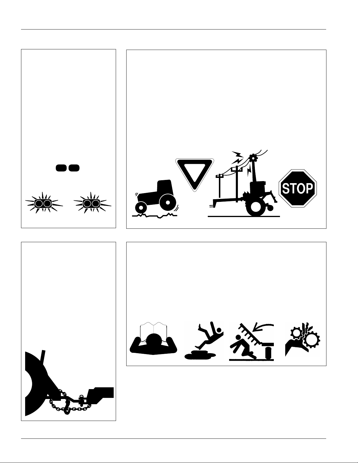
Keep Riders
Off Machinery
Riders obstruct the operator’s view.
Riders could be struck by foreign
objects or thrown from machine.
▲ Never allow riders on implement.
▲ Never allow children to operate
equipment.
For Your Protection
▲ Thoroughly read and understand
Safety Decals, page 4. Read all
instructions noted on decals.
OFF
Shutdown and Storage
▲ Lower machine to ground, put
tractor in park, turn off engine,
and remove key.
▲ Detach and store implement in an
area where children normally do
not play. Secure implement with
blocks and supports.
Handle
Chemicals Properly
Agricultural chemicals can be dangerous. Improper use can seriously
injure persons, animals, plants, soil
and property.
▲ Wear protective clothing.
▲ Handle all chemicals with care.
▲ Follow instructions on container
label.
▲ Avoid inhaling smoke from any
type of chemical fire.
▲ Store or dispose of unused chem-
icals as specified by chemical
manufacturer.
5/26/2006
NTA 1000 and NTA 1300 148-528M
1
Page 4
Great Plains Mfg., Inc.
Important Safety Information
Use Safety
Lights and Devices
Slow-moving tractors, self-propelled
equipment and towed implements
can create a hazard when driven on
public roads. They are difficult to see,
especially at night.
▲ Use flashing warning lights and
turn signals whenever driving on
public roads.
▲ Use lights and devices provided
with implement.
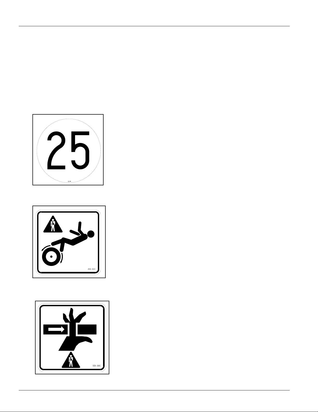
Transport
Machinery Safely
Maximum transport speed for implement is 32 kph (15 mph). Some
rough terrains require a slower
speed. Sudden braking can cause a
towed load to swerve and upset.
▲ Do not exceed 25 kph (15 mph).
Never travel at a speed that does
not allow adequate control of
steering and stopping.
▲ Comply with state and local laws.
▲ Reduce speed if towed load is not
equipped with brakes.
▲ Do not tow an implement that,
when fully loaded, weighs more
than 1.5 times the weight of towing vehicle.
Use A Safety Chain
▲ Use a safety chain to help con-
trol drawn machinery should it
separate from tractor drawbar.
▲ Use a chain with a strength rat-
ing equal to or greater than
gross weight of towed machinery.
▲ Attach chain to tractor drawbar
support or other specified
anchor location. Allow only
enough slack in chain to permit
turning.
▲ Replace chain if any links or end
fittings are broken, stretched or
damaged.
▲ Do not use safety
chain for towing.
Practice Safe Maintenance
▲ Understand procedure before
doing work. Use proper tools and
equipment. Refer to this manual
for additional information.
▲ Work in a clean, dry area.
▲ Lower implement to ground, put
tractor in park, turn off engine,
and remove key before performing
maintenance.
▲ Allow implement to cool completely.
▲ Inspect all parts. Make sure parts
are in good condition and installed
properly.
▲ Remove buildup of grease, oil or
debris.
▲ Remove all tools and unused
parts from implement before operation.
NTA 1000 and NTA 1300 148-528M 5/26/2006
2
Page 5
Great Plains Mfg., Inc.
Important Safety Information
Prepare for Emergencies
▲ Be prepared if a fire starts.
▲ Keep a first-aid kit and fire extin-
guisher handy.
▲ Keep emergency numbers for
doctor, ambulance, hospital and
fire department near phone.
911
Wear
Protective Equipment
▲ Wear protective clothing and
equipment.
▲ Wear clothing and equipment
appropriate for the job. Avoid
loose-fitting clothing.
▲ Because prolonged exposure to
loud noise can cause hearing
impairment or hearing loss, wear
suitable hearing protection such
as earmuffs or earplugs.
▲ Because operating equipment
safely requires your full attention,
avoid wearing radio headphones
while operating machinery.
Avoid High
Pressure Fluids Hazard
Escaping fluid under pressure can
penetrate skin, causing serious
injury.
▲ Avoid the hazard by relieving
pressure before disconnecting
hydraulic lines.
▲ Use a piece of paper or card-
board, not body parts, to check for
suspected leaks.
▲ Wear protective gloves and safety
glasses or goggles when working
with hydraulic systems.
▲ If an accident occurs, see a doc-
tor immediately. Any fluid injected
into the skin must be surgically
removed within a few hours or
gangrene may result.
Safety at All Times
Thoroughly read and understand this
manual before operation. Refer to
Safety Decals, page 4. Read all
instructions noted on decals.
▲ Be familiar with all implement
functions.
▲ Operate implement from driver’s
seat only.
▲ Do not leave tractor or implement
unattended with engine running.
▲ Do not dismount a moving tractor.
Dismounting a moving tractor could
cause serious injury or death.
▲ Do not stand between tractor and
implement during hitching.
▲ Keep hands, feet and clothing
away from power-driven parts.
▲ Wear snug-fitting clothing to avoid
entanglement with moving parts.
▲ Watch out for wires, trees, etc.,
when raising implement. Make
sure all persons are clear of working area.
▲ Do not turn tractor too tight, caus-
ing implement to ride up on
wheels. This could result in injury
or equipment damage.
Tire Safety
Tire changing can be dangerous and
should be performed by trained personnel using correct tools and equipment.
▲ When inflating tires, use a clip-on
chuck and extension hose long
enough to allow you to stand to
one side–NOT in front of or over
the tire assembly. Use a safety
cage if available.
▲ When removing and installing
wheels, use wheel-handling
equipment adequate for weight
involved.
5/26/2006
NTA 1000 and NTA 1300 148-528M
3
Page 6
Great Plains Mfg., Inc.
Safety Decals
Your implement comes equipped with all safety decals in place.
They were designed to help you safely operate your implement.
1. Read and follow decal directions.
2. Keep all safety decals clean and legible.
3. Replace all damaged or missing decals. Order new decals
from your Great Plains dealer. Refer to this section for
proper decal placement.
Important Safety Information
4. When ordering new parts or components, also request corresponding safety decals.
5. To install new decals:
a. Clean the area on which the decal is to be placed.
b. Peel backing from decal. Press firmly on surface,
being careful not to cause air bubbles under decal.
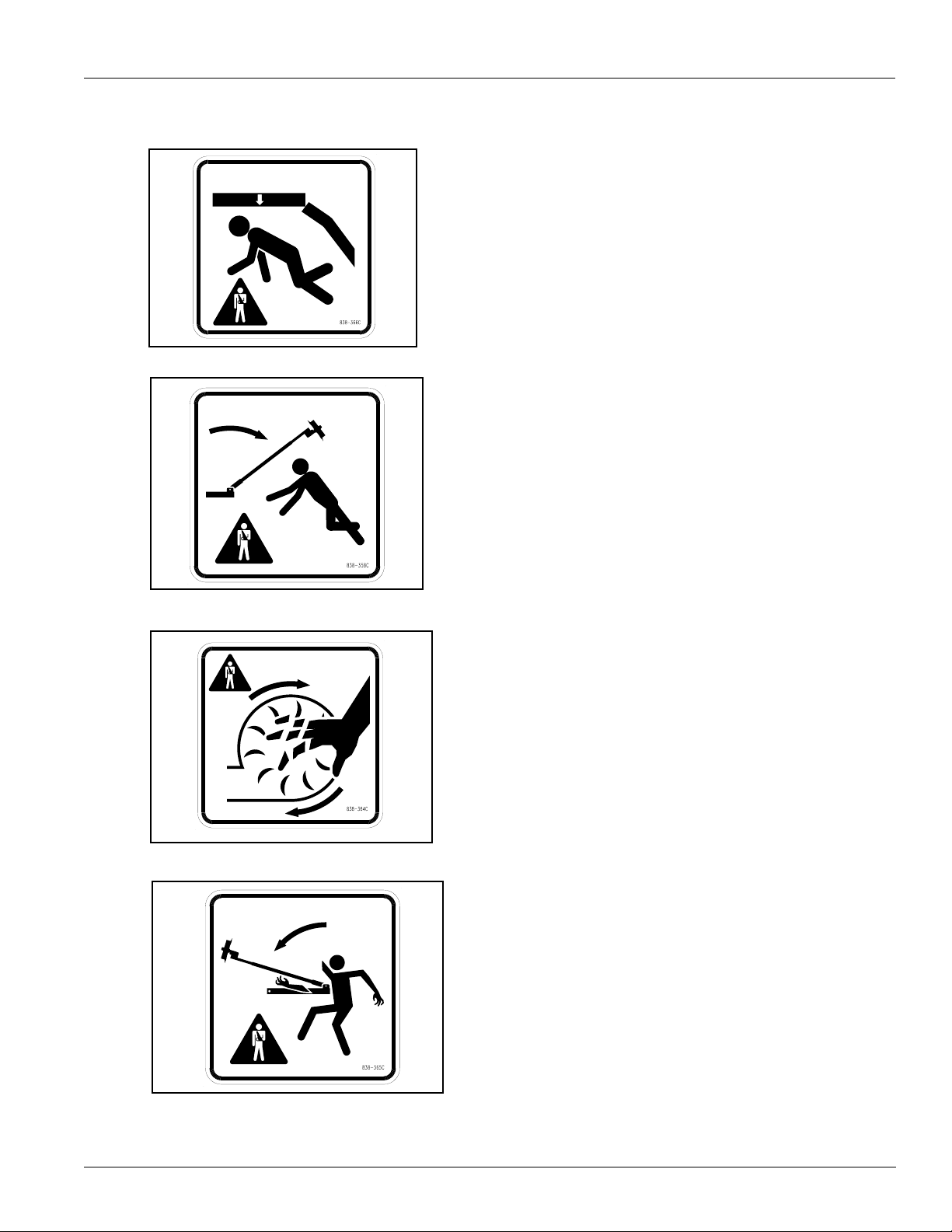
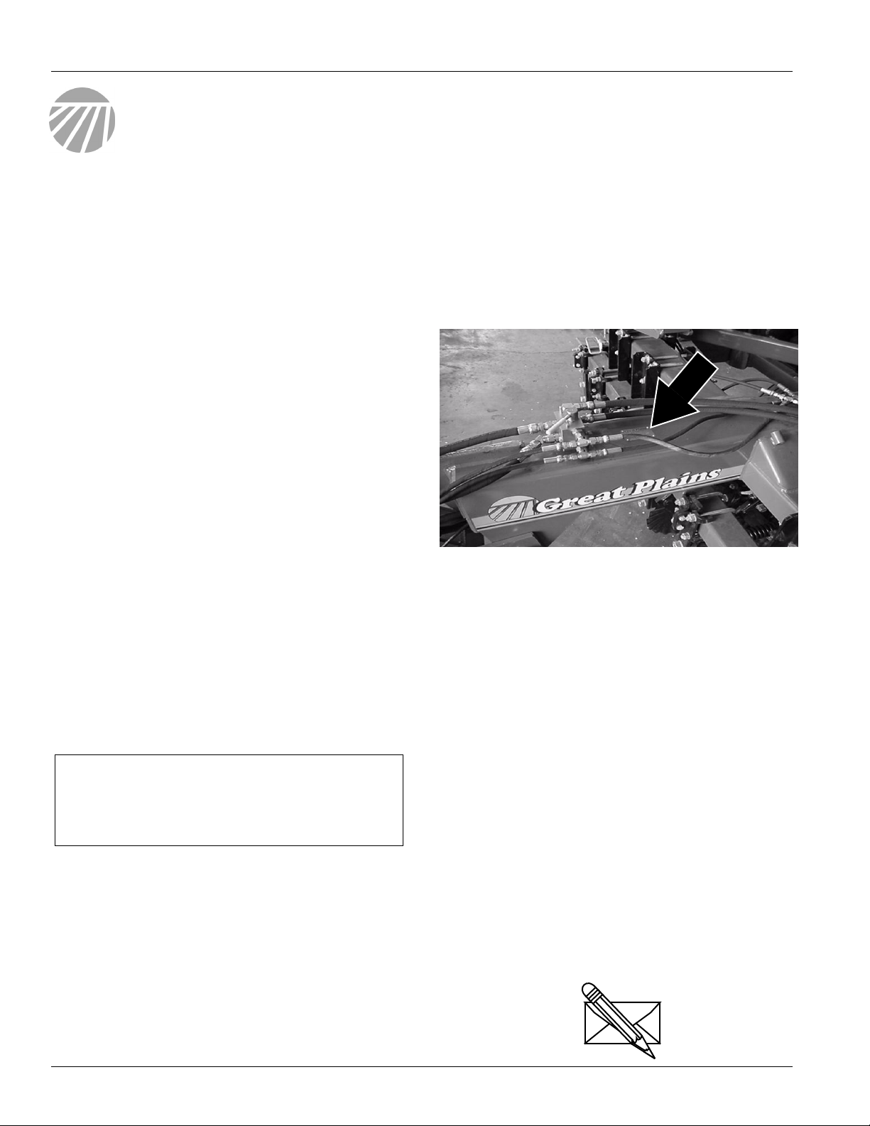
838-369C
Decal 25 KPH Transport
One on rear center of the
sub-frame.
838-362C
Decal Pic-Is not a step
One on each side of H frame.
Two decals total.
838-368C
Decal Pic-Pinch Point
Two on each side of the opener hinge.
Two on each side of the coulter hinge.
Eight decals total.
NTA 1000 and NTA 1300 148-528M 5/26/2006
4
Page 7
Great Plains Mfg., Inc.
Important Safety Information
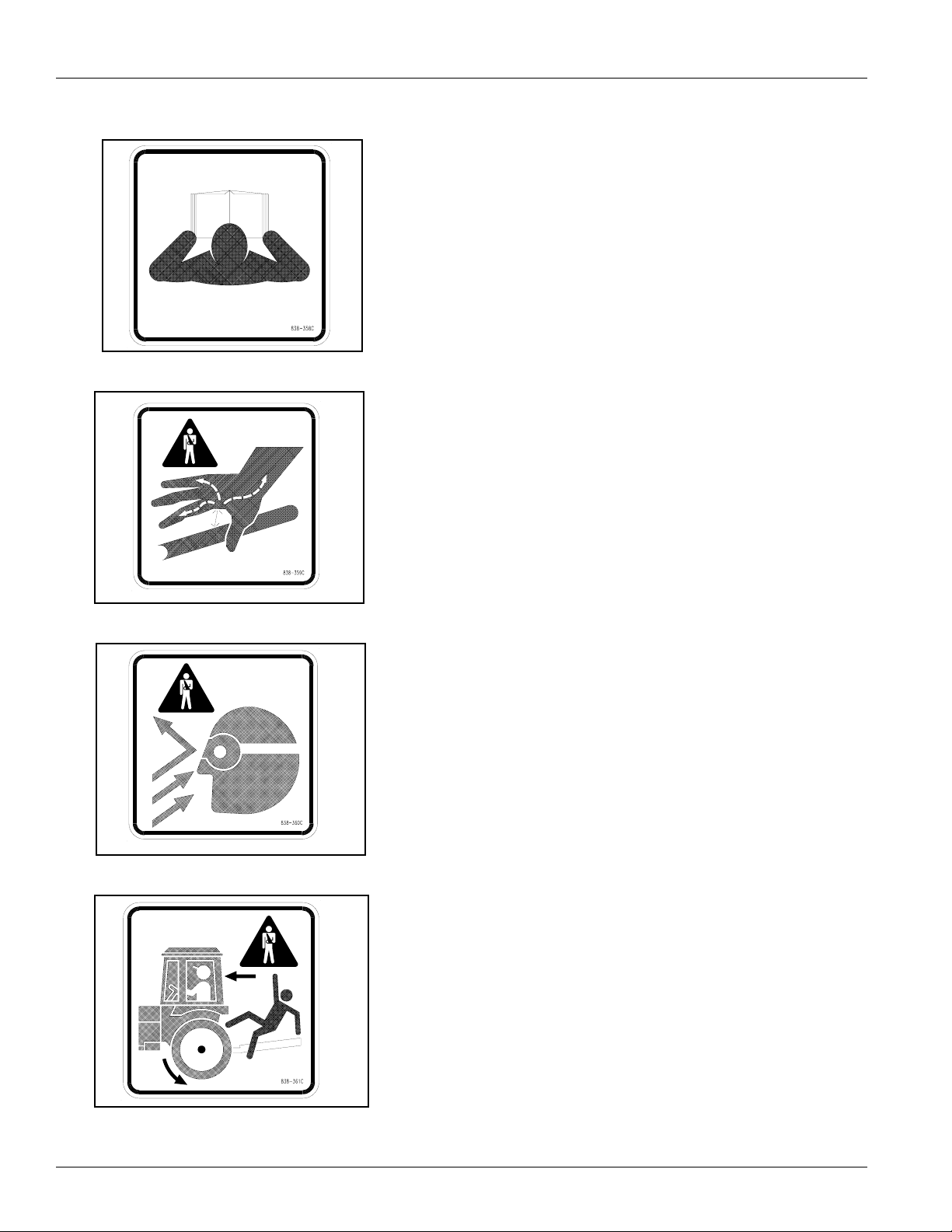
838-366C
Decal Pic-Overhead Crushing
Two on each side of the opener hinge.
Two on each side of the coulter hinge.
Eight decals total.
838-367C
Decal Pic-Overhead Marker
Crushing
One on each Marker brace plate.
Four decals total.
838-364C
Decal Pic-Turning Fan
On on H frame above fan mount.
One decal total.
838-365C
Decal Pic-Marker Pinch Point
One on each Marker brace plate.
Four decal total.
5/26/2006
NTA 1000 and NTA 1300 148-528M
5
Page 8
Great Plains Mfg., Inc.
Important Safety Information
838-358C
Decal Pic-Read Manual
One on tongue.
One decal total.
838-359C
Decal Pic-High Pressure Fluids
One on tongue.
One decal total.
838-360C
Decal Pic-Wear Eye Protection
One on tongue.
One decal total.
838-361C
Decal Pic- Do Not Ride
One on tongue and two on the back
of the sub-frame.
Five decals total.
NTA 1000 and NTA 1300 148-528M 5/26/2006
6
Page 9

Great Plains Mfg., Inc.
Important Safety Information
838-363C
Decal Pic-Moving Chain
One on each chain guard.
Two decals total.
838-266C
Red Reflectors
Two reflectors on outside ends of sign
mounting tube.
Two reflectors total.
838-265C
Amber Reflectors
Two reflectors on both ends of drill.
Two reflectors on the front of drill.
Four reflectors total.
5/26/2006
NTA 1000 and NTA 1300 148-528M
7
Page 10
Great Plains Mfg., Inc.
Introduction
Introduction
Great Plains welcomes you to its growing family of new
product owners. This implement has been designed with
care and built by skilled workers using quality materials.
Proper setup, maintenance and safe operating practices
will help you get years of satisfactory use from the
machine.
Description of Unit
The NTA 1000 and NTA 1300 is a pull-type seeding implement. The implement is mounted on a center-pivot hitch.
The hitch and drill are integrally connected. No-till coulters
are mounted on the hitch to zone-till strips for seed furrows. Straight-arm openers on the drill prepare seedbeds
and place the seed. The pivoting action of the hitch helps
drill openers track the coulters. A contact-drive tire on the
drill powers seeding from a hitch tire. The tongue cylinder
and transport tires control the coulter depth and transport
cylinders raise the drill for turns and transport.
Intended Usage
Use this implement for seeding production-agriculture
crops only. Do not modify implement for use with attachments other than those specified by Great Plains. Use
implement in no till or minimum tillage.
Using This Manual
This manual will familiarize you with safety, assembly,
operation, adjustments, troubleshooting and maintenance. Read this manual and follow the recommendations
to help ensure safe and efficient operation.
The information in this manual is current at printing. Some
parts may change to assure top performance.
Definitions
Right-hand and left-hand as used in this manual are determined by facing the direction the machine will travel while
n use unless otherwise stated.
IMPORTANT: A crucial point of information related to
the preceding topic. For safe and correct operation,
read and follow the directions provided before continuing.
NOTE: Useful information related to the preceding topic.
Owner Assistance
If you need customer service or repair parts, contact a
Great Plains dealer. They have trained personnel, repair
parts and equipment specially designed for Great Plains
products.
Your machine’s parts were specially designed and should
only be replacedwith GreatPlains parts. Always use serial
and model numbers when ordering parts from your Great
Plains dealer. The serial-number plate is located on the
implement as shown in Figure A.
Figure A
Serial Number Plate
Record your implement model and serial numbers here for
quick reference:
Model Number: _________________________________
Serial Numbers: _________________________________
Your Great Plains dealer wants you to be satisfied with
your new machine. If you do not understand any part of
this manual or are not satisfied with the service received,
please take the following actions.
1. Discuss the matter with your dealership service manager. Make sure they are aware of any problems so
they can assist you.
2. If you are still not satisfied, seek out the owner or general manager of the dealership.
3. For further assistance write to:
Product Support
Great Plains Mfg. Inc., Service Department
PO Box 5060
Salina, KS 67402-5060
USA
19346
NTA 1000 and NTA 1300 148-528M 5/26/2006
8
Page 11
Great Plains Mfg., Inc.
Preparation and Set-Up
Preparation and Set-Up
This section will help you prepare your tractor and
implement for use.
Prestart Checklist
1. Read and understand “Important Safety
Information,” page 1.
2. Check that all working parts are moving freely, bolts are
tight, and cotter pins are spread.
3. Check that all grease fittings are in place and
lubricated. Refer to Lubrication,“Maintenance and
Lubrication,” page 29.
4. Check that all safety decals and reflectors are correctly
located and legible. Replace if damaged. See Safety
Decals,“Important Safety Information,”
page 4.
5. Inflate tires to pressure recommended and tighten
wheel bolts as specified. See “Appendix,” page 36.
Wiring Drill
NOTE: If tractor does not comply with ASAE connector, use
the European adapter.
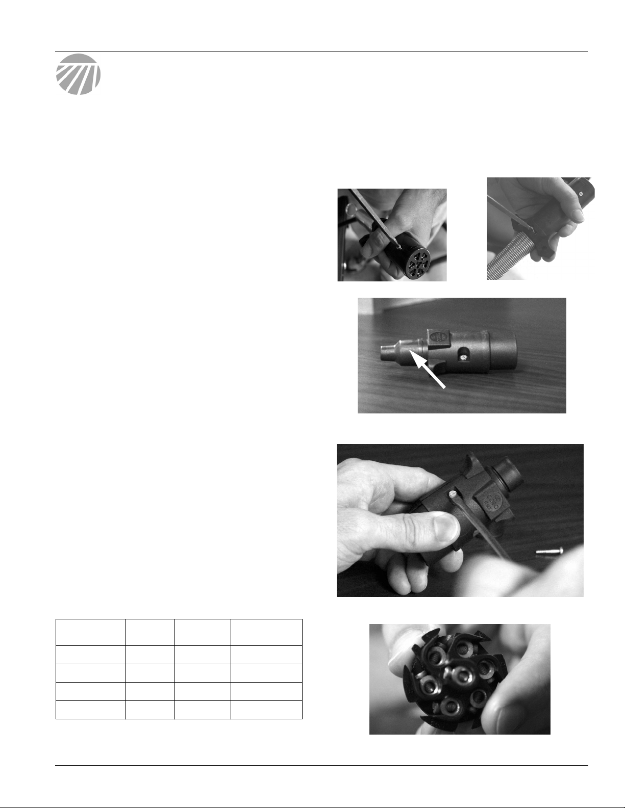
Refer to Figure 1
1. Remove screw from outer casing of ASAE connector.
2. Loosen screw holding wires in place from outer casing
of ASAE connector. Pull outer casing apart. Disconnect wires from connector by removing screws.
3. Completely remove outer casing from wires.
Refer to Figure 2
4. Remove black rubber end piece from European
adapter. Thread wires through black rubber end piece
starting with the smaller end.
Refer to Figure 3
5. Remove the two screws holding the outer casing of the
European adapter together. Keep for reuse.
6. Remove connector from outer casing. Thread wires
under metal bar in bottom of outer casing.
Refer to Figure 4
7. Attach wires to connector using the terminal number
indicators on the back of the connector and the table
below.
Conductor
Identification
Wire
Color
Terminal
Number
Circuit
9. Tighten screws securing wires and metal bar in place.
10. Replace top of outer casing. Insert and tighten screws removed in step 3.
11. Slide black rubber end piece over the end of the outer casing securing the wires.
23264
23254
Figure 1
Removing ASAE Connector
23252
End Piece
Figure 2
European Adapter
Figure 3
Remove Screws to Outer Casing
23265
Wht White 3 Ground
Yel Yellow 1 Left Blinker
Grn Green 4 Right Blinker
Brn Brown 6 Tail Lamps
8. Align connector in bottom of outer casing.
NOTE: BE SURE CONNECTOR AND CASING ARE PROPERLY
ALIGNED, OR CASING WILL NOT FIT CORRECTLY.
5/26/2006
Figure 4
Back of Connecter
NTA 1000 and NTA 1300 148-528M
23255
9
Page 12
Great Plains Mfg., Inc.
Hitching Tractor to Implement
!
DANGER!
You may be severely injured or killed by being crushed between
the tractor and drill. Do not stand or place any part of your
body between drill and moving tractor. Stop tractor engine and
set park brake before installing pins.
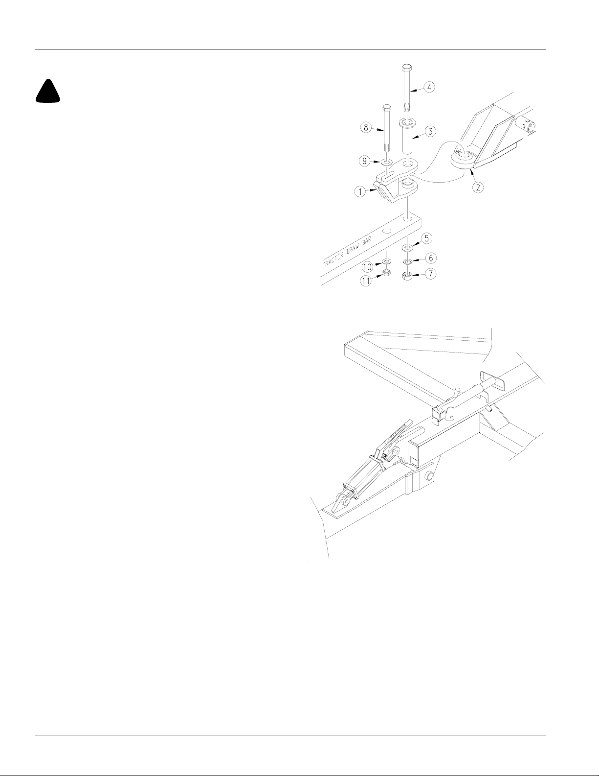
Refer to Figure 5
1. Place hitch weldment (1) over ball swivel on hitch
tongue (2). Hold hitch weldment in place by inserting
spacer tube (3) through hitch clevis and ball swivel.
2. Back tractor up to hitch and bolt hitch weldment to
tractor drawbar using 1-by-10-inch bolt (4), large flat
washer (5), lock washer (6), and nut (7).
3. Use 3/4-by-9-inch bolt (8) to bolt hitch weldment
through its slotted hole and onto secondary hole of
tractor drawbar. Install a 3/4-inch flat washer (9) next
to top slotted hole and fasten with a lock washer (10)
and nut (11). Tighten both bolts.
4. Securely attach safety chain to tractor-drawbar frame.
Refer to Figure 6
5. Remove jack from stob on side of hitch tongue and
place in transport position on implement.
Preparation and Set-Up
Figure 5
Hitch
17215
Figure 6
Jack In Transport
NTA 1000 and NTA 1300 148-528M 5/26/2006
10
19333
Page 13
Great Plains Mfg., Inc.
Hydraulic Hook-up
!
WARNING!
Escaping fluid under pressure can have sufficient force to penetrate the skin. Check all hydraulic lines and hoses before applying pressure. Fluid escaping from a very small hole can be
almost invisible. Use paper or cardboard, not body parts, to
check for suspected leaks. If injured, seek medical assistance
from a doctor that is familiar with this kind of injury. Foreign
fluids in the tissue must be surgically removed within a few
hours or gangrene will result.
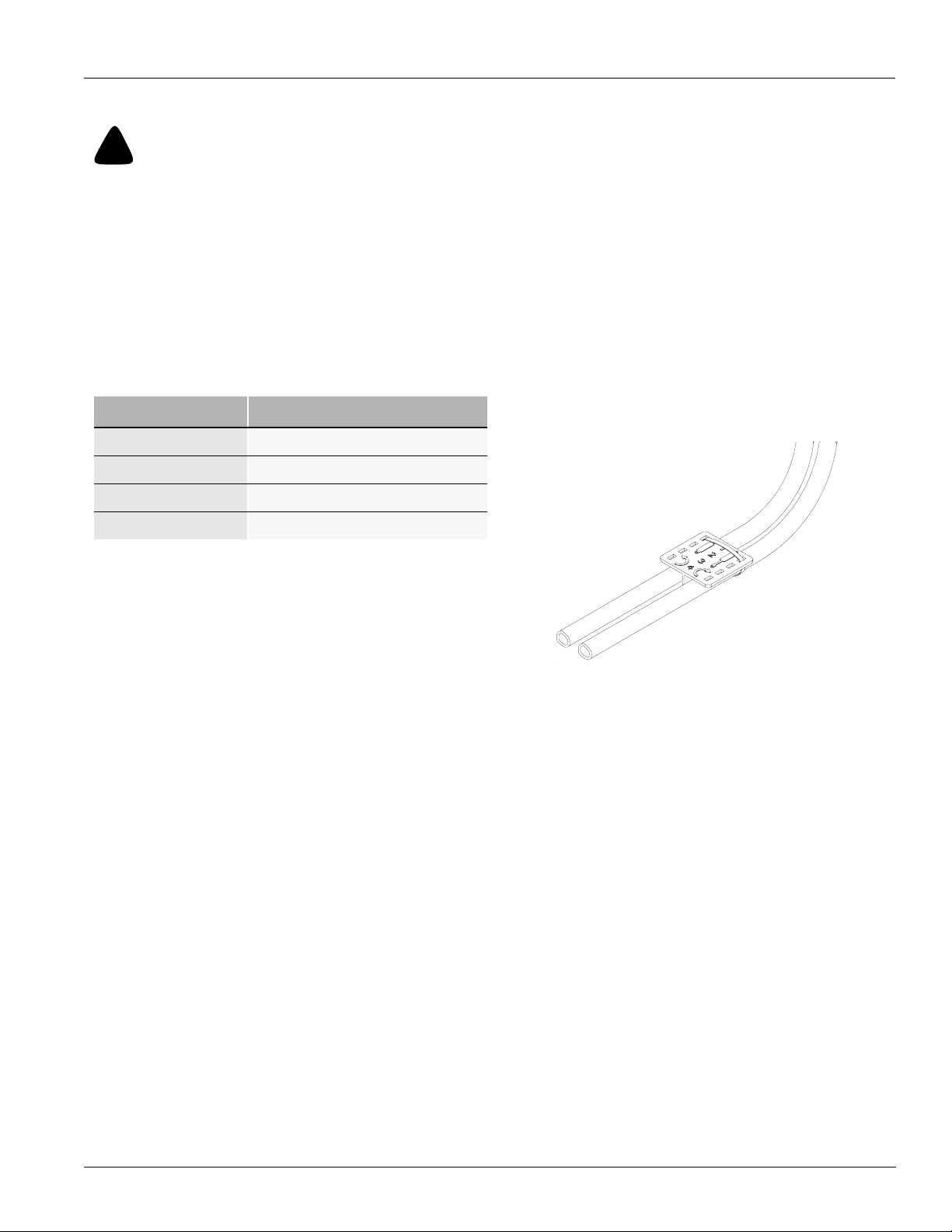
Great Plains hydraulic hoses are colour coded to help
you hook-up hoses to your tractor outlets. Hoses that go
to the same remote valve are marked with the same colour.
Colour Hydraulic Function
Red Transport Lift Cylinders
Blue Tongue Cylinder
Preparation and Set-Up
.
Yellow Fan
Orange Marker
Refer to Figure 7
To distinguish hoses on the same hydraulic circuit, refer
to plastic hose holder. Connect hose under extended
cylinder to outlet you choose for cylinder extension. Connect hose under retracted symbol to outlet for cylinder
retraction.
Connect hydraulic hoses from tongue cylinder to one
tractor remote valve. Connect hoses from transport-lift
cylinders to another tractor remote valve.
17641
Figure 7
Hydraulic Hose Color Ties
5/26/2006
NTA 1000 and NTA 1300 148-528M
11
Page 14

Great Plains Mfg., Inc.
Preparation and Set-Up
Bleeding Hydraulic Systems
!
WARNING!
Escaping fluid under pressure can have sufficient pressure to
penetrate the skin. Check all hydraulic lines and fittings before
applying pressure. Fluid escaping from a very small hole can be
almost invisible. Use paper or cardboard, not body parts, and
wear heavy gloves to check for suspected leaks. If injured, seek
medical assistance from a doctor that is familiar with this type
of injury. Foreign fluids in the tissue must be surgically removed
within a few hours or gangrene will result.
Note: For safe and smooth operation, the hydraulic systems must be free of air. The hydraulic systems should be
bled during initial implement set-up. If they were not bled,
or if you replace a hydraulic component during the life of
the drill, bleed the hydraulics.
Bleeding Lift Hydraulics
The lift system is equipped with rephasing hydraulic cylinders that require a special procedure for bleeding air from
the system. Read and follow the procedure carefully.
1. Check hydraulic fluid level in tractor reservoir and fill to
proper level. Add fluid to system as needed while cycling new cylinders. LIft hydraulic capacity is 23 liters
(6.1 gallons).
2. Lower drill to ground.
3. Unpin rod ends of wheel cylinders. Pivot cylinders up
and wire or otherwise safely support rod ends higher
than base ends. You may need to remove the transport wheel cylinders from the mainframe so you can
orient them with rod ends higher than base ends.
Bleeding Tongue Cylinder
8. Check hydraulic fluid in tractor reservoir and fill to
proper level. Add fluid to system as needed. Tongue
cylinder capacity is 1.89 litres (one-half gallon).
9. Raise and safely support hitch, transport frame and
front tongue.
10. Unpin rod end of tongue cylinder. Block, wire or otherwise safely support cylinder so when rod end is fully
extended it does not contact anything.
11. Cycle cylinder completely in and out at least three
times to purge air from cylinder and hoses.
12. Fully extend cylinder and repin rod end.
13. Recheck tractor reservoir and fill to proper level.
Bleeding Fold Hydraulics
Check hydraulic fluid level in tractor reservoir and fill to
proper level. Add fluid to system as needed while cycling
new cylinders. Fold hydraulic capacity is 5.6 liters (1.5 gallons). If drill fold cylinders have not been extended:
1. Crack fittings at base end of cylinders. Extend cylinders to purge air from system.
2. Crack fittings at rod end of cylinders. Retract cylinders
to purge remaining air from system.
3. Tighten all fittings. Extend cylinders and pin to drill
lugs.
If drill cylinders have been extended:
1. Unfold drill so that fold cylinders are completely extended. Lower drill to ground. Unpin rod ends of fold
cylinders.
2. Crack fittings on rod end of cylinders. Purge air from
cylinders by retracting cylinder rods.
3. Crack fittings at base end of cylinders. Extend cylinders to purge remaining air from system.
4. Tighten all fittings. Repin cylinders to drill.
4. With the tractor engine at idle speed, energize the lift
hydraulics. When the cylinders have extended completely, hold the remote lever on for one minute. Check
all hydraulic hoses, cylinders and fittings for leaks.
5. Retract the cylinder rods. Extend the rods again and
hold the remote lever on for one more minute. Repeat
this step two more times.
6. Again, check all hydraulic hoses, cylinders and fittings
for leaks. Recheck the tractor hydraulic reservoir. Fill
to the proper level.
7. Repin all cylinders.
NTA 1000 and NTA 1300 148-528M 5/26/2006
12
!
CAUTION!
You may be injured or killed by a folding or unfolding opener or
coulter frame.
Page 15

Great Plains Mfg., Inc.
Bleeding Marker Hydraulics
To fold properly, the marker hydraulics must be free of air.
If the markers fold in jerky, uneven motion, follow these
steps.
!
CAUTION!
You may be injured if hit by a folding or unfolding marker.
Markers may fallquickly andunexpectedly ifthe hydraulics fail.
Never allow anyone near the drill when folding or unfolding the
markers.
Check that tractor hydraulic reservoir is full. Marker hydraulic capacity is 1.2 liters (.32 gallons).
1. With both markers lowered into field position, loosen
hydraulic-hose fittings at rod and base ends of marker
cylinders. If applicable, loosen fittings on back side of
sequence valve.
IMPORTANT: Never bleed an O-ring fitting. Instead,
bleed a nearby pipe or JIC fitting.
2. With tractor idling, activate tractor hydraulic valve until
oil seeps out around a loosened fitting. Tighten that fitting.
Preparation and Set-Up
IMPORTANT: JIC fittings do not require high torque. JIC
and O-ring fittings do not require sealant. Always use liquid pipe sealant when adding or replacing pipe-thread fittings. To avoid cracking hydraulic fittings from over
tightening, do not use plastic sealant tape.
3. Reactivate tractor hydraulic valve until oil seeps out
around another loosened fitting. Tighten that fitting.
Repeat process until all loosened fittings have been
bled and tightened.
5/26/2006
NTA 1000 and NTA 1300 148-528M
13
Page 16

Great Plains Mfg., Inc.
Operating Instructions
This section covers general operation. Experience,
machine familiarity, and the following information will lead
to efficient operation and good working habits. Always
operate farm machinery with safety in mind.
Prestart Checklist
1. Carefully read “Important Safety Information,” be-
ginning on page 1.
2. Lubricate implement as indicated under Lubrication,
“Maintenance and Lubrication,” page 29.
3. Check all tires for proper inflation as indicated on Tire
Inflation Chart,“Appendix,” page 36.
4. Check all bolts, pins and fasteners. Torque as specified on Torque Values Chart,“Appendix,” page 36.
5. Check implement for worn or damaged parts. Repair
or replace before going to the field.
6. Check hydraulic hoses, fittings and cylinders for leaks.
Repair or replace before going to the field.
Operating Instructions
Field Operation
1. Hitch implement to a suitable tractor. Refer to Hitching
Tractor to Implement,“Preparation and Setup,” page
9.
2. For proper coulter-to-opener tracking, unlock pivotlock tubes. Refer to Pivot Lock Tubes, page 14.
3. Hydraulically adjust coulters to desired depth. Note
reference measurement on tongue-cylinder gauge to
help you achieve the same coulter depth with each
field pass. Refer to Coulter Depth,“Adjustments,”
page 21, for further adjustment instructions.
4. Set seeding rate. Refer to Roger Manual for Setting
the Seeding Rate.
5. Load box with clean seed.
6. Pull forward, lower coulters to desired depth, lower
drill, and begin seeding.
7. Always lift drill out of ground when turning at row ends
and for other short turns. Seeding will stop automatically as drill is raised and contact drive wheels lose
contact with drive tires..
NTA 1000 and NTA 1300 148-528M 5/26/2006
14
Page 17

Great Plains Mfg., Inc.
Opener Operation
Never back up with openers in ground. If you do, check all
openers to be sure none are clogged or damaged.
For information on seeding depth and opener adjustments, refer to Seeding Depth,“Adjustments,” page 20.
For more information on troubleshooting opener problems, see “Troubleshooting,” page 27.
Pivot Lock Tubes
Refer to Figure 8
The pivot-lock tubes are behind the stabilizer cylinders on
each side of implement.
Refer to Figure 9
During normal fieldoperation, operate hitch with pivot-lock
tubes unsecured so hitch can pivot and drill openers can
properly track coulters.
Refer to Figure 10
When drilling on steep slopes or while transporting,
secure pivot-lock tubes. To lock tubes, turn tubes so they
are horizontal with hitch frame.
You can adjust spring tension on pivot-lock tubes. Refer to
Pivot Lock Tube Adjustment, “Adjustments,” page 26.
Marker Operation
Optional markers are on their own hydraulic circut. They
operate through a sequence valve which alternates lower
and lift cycles between the right hand and left hand
marker.
Fan Operation
Refer to Figure 11
The selector valve diverts the fan circuit to the fold cylinders. This pertains to the NTA 1300 only.
Transport Lift Cylinders
The transport-lift cylinders are rephasing hydraulic cylinders. After a period of normal use, the cylinders may get
out of sequence. If this happens, the hitch will lift unevenly
or one set of tires will not retract from the soil.
To rephase cylinders, raise drill completely and hold
hydraulic lever on for a few seconds to allow cylinders time
to rephase.
Operating Instructions
Figure 8
Pivot Lock Tube
Figure 9
Pivot Lock Tubes Unsecured–Normal Field Position
17129
11880
5/26/2006
Folding
Figure 11
Turn Selector Valve
Fan
19606
10555
Figure 10
Pivot Lock Tubes Secured–Transport Position
NTA 1000 and NTA 1300 148-528M
15
Page 18

Great Plains Mfg., Inc.
Transporting
!
WARNING!
Towing the implement at high speeds or with a vehicle that is
not heavy enough can lead to loss of vehicle control. Loss of vehicle control can lead to serious road accidents, injury and
death. To reduce the hazard:
• Do not exceed 25kph (15 mph).
• Do not tow an implement that, when fully loaded, weighs
more than 1.5 times the weight of the towing vehicle.
1. Check that implement is securely hitched to a sufficient tractor. Refer to Hitching Tractor to Implement,
“Preparation and Setup,” Page 9. Make sure safety
chain is secured to tractor.
2. Unload seed box before transporting if at all possible.
The implement can be transported with a full box of
grain, but added weight will increase stopping distance and decrease maneuverability.
3. Check that tires are properly inflated. Refer to Tire In-
flation Chart,“Appendix,” page 36.
4. Know implement dimensions in transport position.
Choose a route that provides adequate clearance
from all obstructions. Refer to “Specifications and
Capacities,” page 35, for dimensions.
5. Hydraulically lift drill with transport-lift cylinders.
Refer to Figure 12
6. Install transport lock pins in vertical axle tubes.
Refer to Figure 13
7. Secure pivot-lock tubes for transport. Position tubes
so they are horizontal against hitch frame.
Refer to Figure 14
8. Install lock channel over extended tongue-cylinder
rod.
9. Plug light-harness lead into tractor connector. Always
use warning lights when transporting drill.
• Comply with all laws when travelling on public roads.
Operating Instructions
Figure 12
Lock Pin Installed
Figure 13
Pivot Lock Tubes Secured
17208
10555
Figure 14
Lock Chanel Iistalled
NTA 1000 and NTA 1300 148-528M 5/26/2006
16
17217
Page 19

Great Plains Mfg., Inc.
Folding the Drill
!
WARNING!
Pinch Point and Crushing Hazard. To prevent serious injury or death:
• Always lift drill when folding.
• Fold only if hydraulics are bled free of air and fully
charged with hydraulic oil.
• Stay away from frame sections when they are being
raised or lowered.
• Keep away and keep others away when folding or un-
folding drill.
Note: For the NTA 1000 drill, no options, there is no
folding required. Be sure to raise the drill and install
the lock channel to cylinder on tongue frame and
install transport pins in guage wheel legs when
transporting. Refer to figure 12 on the bottom of
this page.
Folding
Figure 15
Valve
Operating Instructions
Fan
19449
Note: For the NTA 1300, no options, there is folding
required when transporting.
Note: Raise and fold the drill on level ground with
the tractor in neutral.
Refer to Figure 15
1. Turn handle on valve to folding position.
Refer to Figure 16
2. Place channel lock and guage wheels pins in
position to lock drill for transporting.
19411
Figure 16
Lock and Pins
19415
5/26/2006
NTA 1000 and NTA 1300 148-528M
17
Page 20

Great Plains Mfg., Inc.
Folding the Drill
!
WARNING!
Pinch Point and Crushing Hazard. To prevent serious injury or
death:
Refer to Figure 17
1. Pull pins (1) and put them in their storage places. Activate hydraulics slowly folding drill until cylinders are
fully stroked. (Coulter cylinders extend to fold and
opener cylinders retract to fold)..
2. I f markers are an option on the drill be sure they are in
the upright position.
Refer to Figure 18
3. If Harrows are an option on the drill, they will need to
be folded by hand. With drill lowered remove pin (1)
and lift extensions over to rest on main harrow frame.
Replace pin in same holes.
4. The chain can also be used to lift the harrows further
up if need be. Grab chain, lift and slide chain link into
slot (2) located to the side of the steps.
Figure 17
Extensions
Operating Instructions
19410
19433
Figure 18
Harrow Extension and chain
19412
NTA 1000 and NTA 1300 148-528M 5/26/2006
18
Page 21

Great Plains Mfg., Inc.
Unfolding the Drill
!
WARNING!
Pinch Point and Crushing Hazard. To prevent serious injury or
death. Be certain the drill is hitched securely to your tractor
drawbar and the hitch safety chain is securely attached to the
tractor before raising or unfolding the drill.
• Unflod the wings with the drill raised..
• Stay away from frame sections when they are being raised
or lowered.
• Keep away and keep others away when folding or unfolding
drill.
Refer to Figure 19
1. Unfold the drill on level ground with the tractor transmission in neutral. Remove the lock channel from the
tongue cylinder and the transport pins from the guage
wheel legs.
2. Slowly lower drill. Place pin in lock position on extensions.
Refer to Figure 20
3. Turn selector valve handle to fan position.
Operating Instructions
19411
19415
Parking
Perform the following steps when parking implement.
Refer to Storage, “Maintenanceand Lubrication,” page 29,
for information on long-term storage preparation.
4. Park implement on a firm, level area. Lower coulters
and drill to ground.
5. Block tires securely to prevent rolling.
6. Release pressure on hydraulic system, then disconnect hydraulic lines. Check that hose ends do not rest
on ground.
7. Move jack from transport position and place it on stob
on side of hitch tongue.
8. Extend jack until all weight is off tractor drawbar. Remove 1-by-10-inch bolt, washer and nut.
9. Disconnect implement light harness, monitor and
power cord.
Folding
Figure 19
Lock and Pins
Figure 20
Valve
Fan
17466
5/26/2006
NTA 1000 and NTA 1300 148-528M
19
Page 22

Great Plains Mfg., Inc.
Adjustments
Seeding Depth
To set drill seeding depth, you must:
• Set coulter depth with tongue cylinder and guage
wheels.
• Set opener depth with T-handles on press wheel.
• If field conditions make it necessary, increase coulter
down pressure by adding tractor weights to frame.
• If necessary, adjust individual coulters or openers to
seed in tire tracks.
The following is an introduction to how the coulters and
double-disk openers are designed to control seeding
depth.
Coulters
A no-till coulter is mounted on the hitch directly ahead of
each opener on the drill. The coulters cut through heavy
trash and make a tilled path in the soil for the openers.
Coulter cutting depth is controlled by the tongue cylinder
and the guage wheels. You also can change the depth of
individual coulters by changing coulter-mounting height.
Refer to Coulter Depth, page 21, for information on these
adjustments.
The amount of coulter down pressure needed to cut a soil
groove varies with soil conditions. Adding weight or shortening the coulter spring increases coulter down pressure
and cutting force. Refer to Coulter Down Pressure, page
21, for more information on these adjustments.
Openers
Opener double disks travel in the coulter path to make a
seed bed. Mounted on the rear of each opener is a press
wheel. The press wheels control opener seeding depth
and firms the seed into the soil.
To maintain a consistent seeding depth, upward press
wheel movement is restricted by an independently adjustable stop on each opener. Moving this stop changes the
depth at which seed is placed. The mounting height of
openers that run in tire tracks also can be changed. Refer
to Opener Depth, page 22, for information on these adjustments.
The amount of opener down pressure needed to cut and
widen the coulter groove and to firm the seed into the soil
varies with soil conditions. Opener down pressure can be
adjusted for all openers or individual openers. Refer to
Opener Down Pressure, page 23, for information on how
to make these adjustments.
Adjustments
NTA 1000 and NTA 1300 148-528M 5/26/2006
20
Page 23

Great Plains Mfg., Inc.
Coulter Depth
Adjust coulters to run 13 to 25 mm (1/2 to 1 inches) below
the drill openers. Coulter depth can be adjusted hydraulically for all coulters or manually for individual coulters.
Hydraulic Control
Make the following adjustment when drilling in level
ground with the seed box half full. .
1. Retract tongue cylinder to transfer the tractor weight to
the coulter toolbar.
Refer to Figure 21
2. Set tongue cylinder so coulters are at desired depth.
Note setting on cylinder gauge so you can return to
the same depth.
NOTE: Use cylinder gauge only as a reference. Gauge
does not measure actual coulter depth.
Refer to Figure 22
3. With coulters and drill lowered to desired seeding
depth, check that hitch frame runs parallel with
ground.
Refer to Figure 23
4. If the hitch frame is not level, remove or replace spacers from transport-lift-cylinder rods until hitch is level.
Adjustments
Figure 3-1
Remove or Install Spacers
17218
Figure 21
Cylinder Gauge
5/26/2006
17854
Figure 22
Levelling Implement
Figure 23
Spacers
NTA 1000 and NTA 1300 148-528M
19434
21
Page 24

Great Plains Mfg., Inc.
Coulter Mounting Height
You can change the depth of individual coulters by adjusting coulter-mounting height. If you adjust coulter height,
be sure to rebolt coulters vertically straight and correctly
spaced. To raise or lower individual coulters:
1. Loosen mounting clampsand adjustcoulter todesired
height. Do not lower coulter spring bar below top ubolts on coulter clamp.
Refer to Figure 24
2. To re-tighten clamps. Snug hex-head clamp bolts (1)
just until u-bolts are tight on each side of spring bar.
3. Tighten nuts (2) on u-bolts.
4. Finish tightening hex-head clamp bolts (1).
NOTE: Even when coulter is held securely, there may be a
gap between clamp halves.
Coulter Down Pressure
Added Weight
Refer to Figure 25
In hard soil conditions where coulter penetration is limited,
you can add suitcase weights to brackets on the hitch
frame. Adding weight on the hitch frame provides the best
weight distribution for no-till drilling.You can add up to
450kg (1000 lbs, on a 3 meter drill) or 590kg (1300lbs, on
a 4 meter drill) of additional weight. Place an equal amount
of weight on each weight bracket.
Coulter Springs
Refer to Figure 26
Coulter-spring length is preset at the factory to 254 mm
(10 inches), giving coulters an initial operating force of 181
kg (400 pounds). This setting is adequate for many difficult
no-till conditions. For lighter no-till conditions where rocks
or other obstructions are a problem, you can reduce coulter down pressure to give coulters better impact
protection. Refer tothe followingchart for adjusting coulter
down pressure.
Adjustments
10300
Figure 24
Individual Coulter Mounting
19406
Figure 25
Weights & Weight Brackets
Spring Length Coulter Down Pressure
267 mm (10 1/2 in) 79 kg (175 lbs)
260 mm (10 1/4 in) 136 kg (300 lbs)
254 mm (10 in) 181 kg (400 lbs)
248 mm (9 3/4 in) 238 kg (525 lbs)
NOTE: Do not reset coulter-spring length shorter than
248 mm (9 3/4 inches). Shortening springs more than 248
mm (9 3/4 inches) may contribute to premature failure of
parts and warranty will be voided.
Figure 26
Coulter Spring
NTA 1000 and NTA 1300 148-528M 5/26/2006
22
13990
Page 25

Great Plains Mfg., Inc.
Opener Depth
When making opener adjustments, keep in mind that
openers will not run any deeper than coulters till the soil.
Press Wheel Adjustment
Refer to Figure 27
Changing the height of the press wheels automatically
changes seeding depth. To adjust, lift T-handle and slide
forward or back.
• For shallower seeding, slide handle ahead toward implement.
• For deeper seeding, slide handle back away from implement.
Opener Mounting Height
Refer to Figure 28
You also can lower individual opener bodies that run in tire
tracks. To lower an opener, move opener-pivot bolt to
lower hole in opener mount.
Adjustments
Shallower
Deeper
16671
16672
Figure 27
Press Wheel Adjustment
Figure 28
Press Wheel Adjustment
5/26/2006
NTA 1000 and NTA 1300 148-528M
23
Page 26

Great Plains Mfg., Inc.
Opener Down Pressure
Refer to Figure 29
To adjust down pressure on individual openers that run in
tire tracks, change opener-spring length. To increase
down pressure, loosen the jam nut at lower end of opener
spring, then turn flange nut. Each additional 6 mm (1/4inch) of spring compression adds about 6 kg (13 pounds)
of pressure. After adjusting flange nut, tighten jam nut.
IMPORTANT: Do not compress spring more than 25
mm (one inch). Compressing spring more than 25 mm
(one inch) could cause opener damage.
Disk Scraper Adjustment
Refer to Figure 30
To keep opener disks turning freely, dirt scrapers are
mounted between disks to clean as the disks rotate. As
field conditions vary, you may need to adjust the scrapers.
To adjust, loosen 3/8-inch bolt and raise or lower scraper
as needed.
Adjustments
16688
Figure 29
Individual Spring Adjustment
16634
Figure 30
Disk Scraper
NTA 1000 and NTA 1300 148-528M 5/26/2006
24
Page 27

Great Plains Mfg., Inc.
Harrow Adjustment
Refer to Figure 31
The illistration shows a successful harrow position for
no-till conditions. Because of different soil moisture,
trash levels and trash types, you may need to reposition the tube frame or tines. Initially position the frame
and tines as shown, then readjust as necessary.
Refer to Figure 31
1. To adjust the frame, loosen the eight hex nuts (1)
on the u-bolts and rotate the frame tube (2) as
necessary.
Refer to Figure 32
2. To adjust the tines, loosen the 1/2-inch hex nuts
(3) on the 1/2-inch u-bolts that attach the tine
tubes to the harrow frames . Rotate tine tubes (4)
so the tines are against the stop bushings andare
angled back as necessary. Re-tighten hex nuts
on u-bolts.
Leaf Spring Adjustment
Refer to Figure 33
A leaf spring is located just ahead of the vertical pivot.
The spring is designed to provide just enough force to
keep the hitch square and stable for turning at field
ends and to add stability for drilling in rough field conditions. Proper leaf-spring adjustment is important for
smooth implement operation.
To adjust properly, square tongue with transport
frame and adjust 3/8-inch u-bolts (1) on each side
until leaf-spring rollers (2) just make contactwith roller
pads (3) on transport frame. Make sure both right and
left sides are adjusted equally.
Adjustments
Figure 31
Tine Angle For No-Till Drilling
5/26/2006
Figure 32
Harrow Adjustment
Figure 33
Leaf Spring Adjustment
NTA 1000 and NTA 1300 148-528M
25
Page 28

Great Plains Mfg., Inc.
Marker Adjustments
Folding Speed
Refer to Figure 34
Adjust folding speed with hex adjustment screws on the
sequence-valve body. There is one adjustment screw for
raising speed (1) and one for lowering speed (2). Identify
adjustment screws by markings stamped in valve body.
With tractor idling at a normal operating speed, adjust
marker folding to a safe speed.Turn adjustment screws
clockwise to decrease folding speed and counterclockwise to increase folding speed. Excessive folding speed
could damage markers and void the warranty.
After adjusting the folding speed, tighten jam nuts on hex
adjustment screws to hold settings.
Disk Adjustments
Refer to Figure 35
If mark left by marker disk is not easy to see, change disk
angle to make a wider mark. Loosen two 1/2-inch carriage
bolts (1) holding disk mount. Rotate disk mount as
desired.
If the marker disk is not square with the ground when the
marker is lowered in the field, or if marker arm tends to fold
up while lowered in the field, change disk angle relative to
ground. Loosen 1/2-inch bolts (2) and rotate marker
mount until marker disk is square with ground.
To adjust where the disk marks, loosen u-bolt (3) and slide
marker-mount tube in or out as necessary. Re-tighten ubolt.
Adjustments
14048
Figure 34
Speed Adjustment, Sequence Valve
15667
Figure 35
Disk Angle
NTA 1000 and NTA 1300 148-528M 5/26/2006
26
Page 29

Great Plains Mfg., Inc.
Pivot Lock Tube Adjustment
Refer to Figure 36
To adjust tension on pivot-lock tubes, loosen jam nut
(1) and screw bolt (2) in or out to desired setting and retightening jam nut. When pivot frame is 90 degrees to
tongue, bolt head should be about 2 mm (1/16 inch)
away from stop on pivot frame (3).
Seed-Lok Lock Up
Refer to Figure 37
Optional Seed-Lok firming wheels provide additional
seed-to-soil contact. The wheels are spring loaded and
do not require adjusting. In some wet and sticky conditions the wheels may accumulate soil.
To lock up firming wheels, hook one end of chain in the
opener-body hole just above the wheel arm (1). Pull
firming-wheel arm (2) up as high as possible and wrap
chain around arm. Hook other end of chain in a link.
Leave no slack in chain; secure wheel arm in its highest
position.
Adjustments
17855
Figure 36
Adjust Tension on Pivot-Lock Tube
1
2
2
16856
Figure 37
Seed Lock
5/26/2006
NTA 1000 and NTA 1300 148-528M
27
Page 30

Great Plains Mfg., Inc.
Troubleshooting
Problem Solution
Troubleshooting
Drill raising and lowering rough and uneven Check for too little play in slide-block area. Refer to Maintenance, “Mainte-
Coulters not going deep enough
Drill not tracking behind coulters
Openers plugging in no-till conditions Drill across standing residue.
Drill Seeding too deep
Uneven seed spacing or uneven stand
Opener disks not turning freely
nance and Lubrication,” Page 29.
Check for air trapped in hydraulic lines or cylinders. Bleed hydraulics if necessary. Refer to Bleeding the Hydraulic Systems, “Preparation and Setup,”
page 9.
Retract tongue cylinder.
Add weight to hitch frame. Refer to Coulter Down Pressure, “Adjustments,”
Page 23.
Too much weight is being used by openers; set drill openers to lightest
spring setting. Refer to Opener Down Pressure, “Adjustments,” page 24.
Shorten coulter springs to increase down pressure. Refer to Coulter Spring ,
“Adjustments,” Page 21.
Lower Coulters on Frame. Refer to Coulter Depth, page 20.
Check if coulters are aligned with openers.
Check that pivot-lock tubes are in drilling position, page 14.
Check if leaf spring is out of alignment. Refer to Leaf Spring Adjustment,
“Adjustments,” page 24.
Change the press-wheel setting. Refer to Opener Depth, “Adjustments,”
page 22..
Remove weight from hitch.
Check for plugging in seed cups.
Check if seed tubes are plugged.
Reduce ground speed.
Check that opener disks turn freely.
Increase opener down pressure so opener disks penetrate. Refer to Opener
Down Pressure, “Adjustments,” page 23..
Check for trash or mud build-up on optional Seed-Lok® wheels.
Check for trash or mud build-up on disk scrapers. Readjust scrapers. Refer
to Disk Scraper Adjustment, “Adjustments,” page 24.
Check if scrapers are too tight, restricting disk movement. Refer to Disk
Scraper Adjustment, “Adjustments,” page 24.
Check disk bearings.
Check opener frame for possible damage.
Check if opener disks turn freely by hand but not in field. If so, reduce down
pressure on openers. Refer to Opener Down Pressure, “Adjustments,” page
24.
Check press-wheel adjustment for seeding depth. Refer to Opener Depth,
“Adjustments,” page 22.
Actual seeding rate
Check see-rate setting. Refer to “Roger” manual.
is different than desired
NTA 1000 and NTA 1300 148-528M 5/26/2006
28
Page 31

Great Plains Mfg., Inc.
Problem Solution
Troubleshooting
Excessive seed cracking
Uneven seeding depth
Press wheel not
compacting soil as desired
Press wheels or openers plugging
Use a faster drive type and a lower seed-rate-handle setting.
Position seed-cup handles to a lower notch.
Check that openers have sufficient down pressure. Refer to Opener Down
Pressure, “Adjustments,” page 24.
Reset press-wheel depth. Refer to Opener Depth, “Adjustments,” page 23.
Increase down pressure on openers. Refer to Opener Down Pressure,
“Adjustments,” page 24.
Consider field conditions. Drilling in damp or wet conditions may increase
this problem.
Reduce down pressure on openers. Refer to Opener Down Pressure,
“Adjustments,” page 24.
Do not back up or stop and allow drill to roll back with openers in ground.
Check optional Seed-Lok® wheels.
5/26/2006
NTA 1000 and NTA 1300 148-528M
29
Page 32

Great Plains Mfg., Inc.
Maintenance and Lubrication
Proper servicing and adjustment are key to long life of any
farm implement. With careful and systematic inspection
you can avoid costly maintenance, time and repair.
Always turn off and remove tractor key before making any
adjustments or performing any maintenance.
!
WARNING!
You may be severely injured or killed by being crushed by the
falling implement. Always have transport locks in place and
frame sufficiently blocked up when working on implement.
Maintenance and Lubrication
!
WARNING!
Escaping fluid under pressure can have sufficient pressure to
penetrate the skin. Check all hydraulic lines and fittings before
applying pressure. Fluid escaping from a very small hole can be
almost invisible. Use paper or cardboard, not body parts, and
wear heavy gloves to check for suspected leaks. If injured, seek
medical assistance from a doctor that is familiar with this type
of injury. Foreign fluids in the tissue must be surgically removed
within a few hours or gangrene will result.
1. After using implement for several hours, check all
bolts to be sure they are tight.
2. Inflate tires as specified on Tire Inflation Chart,“Ap-
pendix,” page 37.
3. Replace any worn, damaged or illegible safety decals.
Obtain new decals from your Great Plains dealer. Refer to Safety Decals,“Important Safety Information,”
page 4 for decal placement.
4. Check drill drive chains for wear. Replace if necessary. Adjust idlers to remove excess slack from
chains.
Refer to Figures 38 and 39
Keep front slide blocks (1) on transport axles adjusted to
within 0.381 to 0.635 mm (0.015 to 0.025 inch) of inneraxle tubes (2).
1
2
19406
Figure 38
Slide Block Adjustment
Figure 39
SlideBlock Adjustment
NTA 1000 and NTA 1300 148-528M 5/26/2006
30
Page 33

Great Plains Mfg., Inc.
Refer to Figure 40
If cylinders are removed or inner-axle-slideblocks become
worn, assemble or adjust support braces as follows. Use
this procedure for both support bolts on the transport-lift
cylinders.
1. Assemble 1/2-by-5 1/2-inch, full-thread bolt (1) to cylinder support brace (2), bolted to rod end cylinder
casting.
2. Screw on three 1/2-inch jam nuts (3) and one 1/2-inch
washer (4) as shown. Tighten first jam nut against cylinder support (2) and run other two jam nuts on nearly
all the way.
3. Install cylinder with support bolts (1) extending
through bracket (5) on outer slide tube and pin both
base end and rod end.
4. Screw outer 1/2-inch jam nut out until 1/2-inch washer
(4) just touches bracket on outer slide tube. Do not put
pressure on the cylinder by tightening the 1/2-inch jam
nut. Once washer touches bracket, lock outer 1/2-inch
jam nut in place with centre 1/2-inch jam nut.
5. Install spring (6) and 1/2-inch nylock nut (7). Tighten
nut to compress spring to 32 mm (1 1/4 inches).
Maintenance and Lubrication
12090
Storage
Store implement where children do not play. If possible,
store inside for longer implement life.
1. Clean implement as necessary. Be sure seed boxes
are cleaned completely before storing.
2. Lubricate all fittings as indicated under Lubrication,
page 31.
When in storage, lower openers on a board or hard surface. Apply a light coat of oil to exposed cylinder rods.
Figure 40
Support Brace
5/26/2006
NTA 1000 and NTA 1300 148-528M
31
Page 34

Great Plains Mfg., Inc.
Lubrication
Maintenance and Lubrication
Lubrication
Legend
Multipurpose
spray lube
Multipurpose
grease lube
Vertical Pivot Bushings, Top and Bottom
Two zerks on back of vertical-pivot tube on transport
frame
Lubricant = Grease
Quantity = Until grease begins to emerge
Multipurpose
oil lube
50
Intervals at which
lubrication is required
8
12110
12111
8
Coulter Swing Arm Pivot
Located on top of each coulter casting
Lubricant = Grease
Quantity = Until grease begins to emerge
Seasonally
Coulter Hub Bearings
Located on each coulter hub
Lubricant = Grease
Quantity = Force grease into tapered roller bearings, but
do not pressurize cavity enough to blow out seal or hub
cap
NTA 1000 and NTA 1300 148-528M 5/26/2006
32
Page 35

Great Plains Mfg., Inc.
12112
Maintenance and Lubrication
8
Tongue to Main Frame Pivot
Located at rear of tongue
Lubricant = Grease
Quantity = Until grease begins to emerge
19435
As
Required
Drive Chains
Lubricant = Chain Lube
Quantity = Spray Thoroughly
5/26/2006
NTA 1000 and NTA 1300 148-528M
33
Page 36

Great Plains Mfg., Inc.
12133
Maintenance and Lubrication
Seasonally
Transport Wheel Bearings
Lubricant = Grease
Quantity = Repack bearings and check seals
Optional Folding Markers
Lubricant = Grease
Quantity = Until grease begins to emerge
Optional Folding Markers
10
Seasonally
Lubricant = Grease
Quantity = Repack bearings
NTA 1000 and NTA 1300 148-528M 5/26/2006
34
Page 37

Great Plains Mfg., Inc.
Options
Options
Harrow Attachment
The coil-tine harrow finishes no-till surfaces by levelling
and distributing residue for enhanced seed emergence.
For information on how to adjust the harrow, refer to Har-
row Adjustment,“Adjustments,” page 24.
To order the harrow attachment, contact your Great Plains
dealer.
Option Part Number
Harrow Attachment 1000 148-547A
Harrow Attachment 1300 148-548A
12677
Markers
Hydraulic markers are available. The units have a notched
blade to leave a mark for you to follow on the next field
pass. Markers are sold as dual units and are equipped
with a sequence valve for easy operation.
For information on how to operate the markers, refer to
Field Operation and Transporting,“Operating Instruc-
tions,” page 14. For information on how to adjust the
markers, refer to Marker Adjustments,“Adjustment,”.For
information on lubricating the markers, refer to Lubrica-
tion,“Maintenance and Lubrication,” page 32.
To order markers, contact your Great Plains dealer.
Option Part Number
Dual Markers 148-541A
Seed-Lok Firming Wheels
Seed-Lok firming wheels press seed directly into the bottom of the seed trench. By firming all seeds into the moist
soil at a uniform depth, Seed-Lok promotes more even
plant emergence and higher yields.
For information on adjusting Seed-Lok firming wheels,
refer to Seed-Lok Lock Up,“Adjustments,” page 26.
To order Seed-Lok, contact your Great Plains dealer.
Option Part
Number
Removable 5-in. Seed-Lok, 00 and 10 Series Openers 122-193K
5/26/2006
NTA 1000 and NTA 1300 148-528M
35
Page 38

Great Plains Mfg., Inc.
20115
Specifications and Capacities
Agtron Blockage Kit
A sensor installed in the seed delivery hoses to indicate
hose blockage.
To order the Agtron Blockage Kit, contact your Great
Plains dealer.
Option Part Number
NTA1000 Agtron Blockage Kit 148-648A
NTA1300 Agtron Blockage Kit 148-649A
Specifications and Capacities
Row Spacing
Rows Per Drill
Weight*
Working Width
Transport Width
Transport Height
Length
Seedbox Capacity
Tires
Tractor Requirements
Hydraulics**
*Listed weight includes markers, fertilizer and small-seeds options.
** An additional pair of outlets will be needed for the optinal markers.
16.66 cm (6 9/16in.) 16.66 cm (6 9/16in.)
18 24
4080 kg (9000lbs) 4850 kg (10700lbs)
3 m (9 ft. 10 1/8 in.) 4 m (13 ft)
3 m (9 ft. 10 in.) 3 m (9 ft. 10 in.)
312 cm (10’-3”) 312 cm (10’-3”)
647 cm (21’-3”) 647 cm (21’-3”)
1500 L (43 bu) 2000 L (57 bu)
NTA 1000 NTA 1300
13.0/55-16 12 PR
92 kw 120 kw
Three pair of hydraulic remotes:
1-Pair for the fan/fold circuit
1-Pair for the lift
1-Pair for the tongue cylinder
NTA 1000 and NTA 1300 148-528M 5/26/2006
36
Page 39

Great Plains Mfg., Inc.
Appendix
Torque Values Chart for Common Bolt Sizes
Appendix
Bolt Head Identification
Bolt
1
in-tpi
1/4" - 20 7.4 5.6 11 8 16 12 M 5 X 0.8 436597
1/4" - 28 8.5 6 13 10 18 14 M 6 X 1 7 5 11 8 15 11
5/16 - 18 15 11 24 17 33 25 M 8 X 1.25 17 12 26 19 36 27
5/16" - 24 17 13 26 19 37 27 M 8 X 1 18 13 28 21 39 29
3/8" - 16 27 20 42 31 59 44 M10 X 1.5 33 24 52 39 72 53
3/8" - 24 31 22 47 35 67 49 M10 X 0.75 39 29 61 45 85 62
7/16" - 14 43 32 67 49 95 70 M12 X 1.75 58 42 91 67 125 93
7/16" - 20 49 36 75 55 105 78 M12 X 1.5 60 44 95 70 130 97
1/2" - 13 66 49 105 76 145 105 M12 X 1 90 66 105 77 145 105
1/2" - 20 75 55 115 85 165 120 M14 X 2 92 68 145 105 200 150
9/16" - 12 95 70 150 110 210 155 M14 X 1.5 99 73 155 115 215 160
9/16" - 18 105 79 165 120 235 170 M16 X 2 145 105 225 165 315 230
5/8" - 11 130 97 205 150 285 210 M16 X 1.5 155 115 240 180 335 245
5/8" - 18 150 110 230 170 325 240 M18 X 2.5 195 145 310 230 405 300
3/4" - 10 235 170 360 265 510 375 M18 X 1.5 220 165 350 260 485 355
3/4" - 16 260 190 405 295 570 420 M20 X 2.5 280 205 440 325 610 450
7/8" - 9 225 165 585 430 820 605 M20 X 1.5 310 230 650 480 900 665
7/8" - 14 250 185 640 475 905 670 M24 X 3 480 355 760 560 1050 780
1" - 8 340 250 875 645 1230 910 M24 X 2 525 390 830 610 1150 845
1" - 12 370 275 955 705 1350 995 M30 X 3.5 960 705 1510 1120 2100 1550
1-1/8" - 7 480 355 1080 795 1750 1290 M30 X 2 1060 785 1680 1240 2320 1710
1 1/8" - 12 540 395 1210 890 1960 1440 M36 X 3.5 1730 1270 2650 1950 3660 2700
1 1/4" - 7 680 500 1520 1120 2460 1820 M36 X 2 1880 1380 2960 2190 4100 3220
1 1/4" - 12 750 555 1680 1240 2730 2010
1 3/8" - 6 890 655 1990 1470 3230 2380
1 3/8" - 12 1010 745 2270 1670 3680 2710
1 1/2" - 6 1180 870 2640 1950 4290 3160
1 1/2" - 12 1330 980 2970 2190 4820 3560
Grade 2 Grade 5
N · m2ft-lb3N · m ft-lb N · m ft-lb mm x pitch4N · m ft-lb N · m ft-lb N · m ft-lb
Torque tolerance + 0%, -15% of torquing values. Unless otherwise specified use torque values listed above.
Grade 8
Bolt
1
in-tpi = nominal thread diameter in inches-threads per inch
4
mm x pitch = nominal thread diameter in millimeters x thread pitch
Bolt Head Identification
5.8 8.8 10.9
Class 5.8 Class 8.8 Class 10.9
2
N· m = newton-meters
3
ft-lb= foot pounds
Tire Inflation Chart
Tire Size Inflation PSI Tire Size Inflation PSI
Contact Wheel 40 13.05/55-16 12PR 65
2.75 bar 4.48 bar
NOTE: All tires are warranted by the original manufacturer of the tire. Tire warranty information can be found in the brochures included with your Operator’s and Parts Manuals or online at the manufacturer’s websites. For service assistance
or information, contact your nearest Authorized Farm Tire Retailer.
Manufacturer Website
Titan www.titan-intl.com
Goodyear www.goodyearag.com
Firestone www.firestoneag.com
5/26/2006
NTA 1000 and NTA 1300 148-528M
37
Page 40

Great Plains Mfg., Inc.
Appendix
Warranty
Great Plains Manufacturing, Incorporated warrants to the original purchaser that this seeding equipment will be free from defects in material
and workmanship for a period of one year from the date of original purchase when used as intended and under normal service and conditions
for personal use; 90 days for commercial or rental purposes. This Warranty is limited to the replacement of any defective part by Great Plains
Manufacturing, Incorporated and the installation by the dealer of any
such replacement part. Great Plains reserves the right to inspect any
equipment or part which are claimed to have been defective in material
or workmanship.
This Warranty does not apply to any part or product which in Great
Plains’ judgement shall have been misused or damaged by accident or
lack of normal maintenance or care, or which has been repaired or altered in a way which adversely affects its performance or reliability, or
which has been used for a purpose for which the product is not designed. This Warranty shall not apply if the product is towed at a speed
in excess of 20 miles per hour.
Claims under this Warranty must be made to the dealer which originally
sold the product and all warranty adjustments must by made through
such dealer. Great Plains reserves the right to make changes in materials or design of the product at any time without notice.
This Warranty shall not be interpreted to render Great Plains liable for
damages of any kind, direct, consequential, or contingent, to property.
Furthermore, Great Plains shall not be liable for damages resulting from
any cause beyond its reasonable control. This Warranty does not extend to loss of crops, losses caused by harvest delays or any expense
or loss for labor, supplies, rental machinery or for any other reason.
No other warranty of any kind whatsoever, express or implied, is
made with respect to this sale; and all implied warranties of merchantability and fitness for a particular purpose which exceed
the obligations set forth in this written warranty are hereby disclaimed and excluded from this sale.
This Warranty is not valid unless registered with Great Plains Manufacturing, Incorporated within 10 days from the date of original purchase.
NTA 1000 and NTA 1300 148-528M 5/26/2006
38
Page 41

Great Plains Manufacturing, Inc.
Corporate Office: P.O. Box 5060
Salina, Kansas 67402-5060 USA
 Loading...