

Page 1

Table of Contents Index
2013+ NP4000, NP4000A and NP4000B
Nutri-Pro® 40-Foot Fertilizer Applicator
Operator Manual
Manufacturing, Inc.
www.greatplainsmfg.com
Read the operator manual entirely. When you see this symbol, the
subsequent instructions and warnings are serious - follow without
exception. Your life and the lives of others depend on it!
34950
Illustrations may show optional equipment not supplied with standard unit, or may show
prior year NP3000, NP4000, or NP30 or NP40 models where the topic function is
identical.
ORIGINAL INSTRUCTIONS
© Copyright 2014 Printed 2014-05-14 417-199M
Table of Contents Index
EN
Page 2

Table of Contents Index
Table of Contents Index
Page 3

Great Plains Manufacturing, Inc. Cover Index iii
Table of Contents
Important Safety Information ...................................... 1
Anhydrous Ammonia Safety...........................................1
Safety Decals ................................................................. 9
Introduction ................................................................18
Description of Unit ........................................................18
Models Covered .......................................................18
Intended Usage ........................................................18
Document Family......................................................18
Using This Manual........................................................19
Owner Assistance ........................................................20
Application Overview.................................................21
Anhydrous: System Components.................................21
NH3 System Narrative ..............................................22
Conventional Liquid: Applicator System Components .28
Hydraulic Drive System Components (Options) .......28
Ground Drive System Components (Options)..........29
Liquid System Narrative ...........................................30
Trailing Nurse Tank Components.................................33
Nutri-Pro® Rear Hitch (Option).....................................33
Hitch (Option) and Nurse Tank Components (User-Pro-
visioned) ...........................................................34
Preparation and Setup ...............................................35
Initial Setup...................................................................35
Post-Delivery/Seasonal Setup......................................35
NP4000A: Get Expert Advice .......................................36
Pre-Application Setup...................................................36
Hitching Tractor to Applicator .......................................36
2-Point Hitching ........................................................37
NP4000A: Emergency Shut-Off Rope......................38
Electrical Hookup......................................................40
Hydraulic Hose Hookup............................................ 41
Hydraulic Pump Hookup (Option).........................42
Raise Parking Stands...............................................42
Leveling Applicator .......................................................43
Meter / Variable Rate Setup (Option) ...........................44
Raven SCS 450 Setup Data:................................46
Wash Water (NP4000A)...............................................47
Sealer Setup (NP4000A)..............................................47
Operating Instructions...............................................48
Pre-Start Checklist .......................................................48
Fold/Lift Circuit .............................................................49
FOLD / FIELD Switch ...................................................49
Applicator Locks ...........................................................50
Raising/Lowering Applicator.........................................51
Raise For Transport (Folded)............................... 51
Raise Pre-Folding (from Unfolded) ...................... 52
Field Lift................................................................ 53
Lower While Folded ............................................. 54
Lower While Unfolded .......................................... 54
Field Lower........................................................... 55
Unfolding and Folding .................................................. 56
Unfolding (At Field) .............................................. 56
Unfolding (Parking, Storage, Service).................. 57
Folding ................................................................. 58
Transport...................................................................... 59
Transport Steps........................................................ 60
Final Applicator Setup.................................................. 60
NH3 Operations............................................................ 61
NH3 Nurse Tanks ..................................................... 61
NH3: Safing Applicator Before Cart Hitch................. 61
NH3: Check Hydrostatic Relief Valves ..................... 62
NH3: Close Bleed Valves ......................................... 62
NH3: Check Hose Discharged.................................. 62
NH3: Hitching Nurse Tank........................................63
NH3: Mechanical Cart Hitching ............................ 63
NH3: Making Nurse Tank Connections .................... 64
NH3: Connect Cart Hose...................................... 65
NH3: Dry Run ........................................................... 65
NH3: Pass Planning ................................................. 66
NH3: Start of Pass Planning................................. 66
NH3: Monitor Operation............................................ 67
NH3: Field Application .............................................. 67
NH3: Starting Tank Flow ...................................... 67
NH3: Starting Application ..................................... 68
NH3: Suspending Application............................... 69
NH3: Field Turns .................................................. 69
NH3: Stopping Application.................................... 70
NH3: Breakaway Event ............................................ 71
NH3: Unhitching Nurse Tank....................................73
NH3: Exchanging Nurse Tanks ............................73
NH3: Final Nurse Tank Unhitch............................ 73
Liquid Operations......................................................... 74
Liq: Filling On-Board Tanks...................................... 74
Liq: Tank Quick-Fill .............................................. 74
Liq: Tank Lid Fill ................................................... 75
Liq: Hitching Conventional Nurse Tank....................76
Liq: Mechanical Cart Hitching .............................. 76
Liq: Making Nurse Tank Connections ..................76
Liq: Ground Drive Pump Start-Up ............................ 77
Liq: Prime the Ground Drive System.................... 77
Liq: Hydraulic Drive Start-Up.................................... 77
© Copyright 2010, 2011, 2012, 2013, 2014 All rights Reserved
Great Plains Manufacturing, Inc. provides this publication “as is” without warranty of any kind, either expressed or implied. While every precaution has been
taken in the preparation of this manual, Great Plains Manufacturing, Inc. assumes no responsibility for errors or omissions. Neither is any liability assumed for
damages resulting from the use of the information contained herein. Great Plains Manufacturing, Inc. reserves the right to revise and improve its products as
it sees fit. This publication describes the state of this product at the time of its publication, and may not reflect the product in the future.
2014-05-14 Cover Index 417-199M
Trademarks of Great Plains Manufacturing, Inc. include: Singulator Plus, Swath Command, Terra-Tine.
Registered Trademarks of Great Plains Manufacturing, Inc. include:
Air-Pro, Clear-Shot, Discovator, Great Plains, Land Pride, MeterCone, Nutri-Pro, Seed-Lok, Solid Stand,
Terra-Guard, Turbo-Chisel, Turbo-Chopper, Turbo Max, Turbo-Till, Ultra-Till, Ver ti-Till, Whirlfilter, Yield-Pro.
Brand and Product Names that appear and are owned by others are trademarks of their respective owners.
Page 4

iv 2013+ NP4000/A/B Table of Contents Index Great Plains Manufacturing, Inc.
Liq: Field Operations (Either Pump)......................... 77
Liq: Fertilizer Operation............................................ 78
Liq: Monitor Operation (Option) ............................... 79
Suspending Application ........................................... 79
Liq: Stopping Application ......................................... 79
Field Set-Up Checklists................................................ 80
Field Operation Checklists ........................................... 82
Short-Term Parking...................................................... 84
Long-Term Storage...................................................... 84
Adjustments ............................................................... 85
Row Adjustments ......................................................... 86
Anhydrous Coulter Application Depth ...................... 86
Depth Reference Information ............................... 86
Anhydrous Coulter Castering ............................... 86
Sealer Adjustments .......................................... 87
NH
3
Sealer Down-Pressure Adjustment ...................... 87
Sealer Spacing or Setback Adjustment................ 87
Sealer Angle Adjustment...................................... 87
Terra-Tine™ Adjustments (Option).......................... 88
Vantage I Coulter Adjustments ................................ 89
Vantage I Coulter Height and Castering .............. 90
Tool Bar Height Adjustment ......................................... 91
Weight Transfer Adjustment ........................................ 92
Weight Transfer Safety Information ......................... 92
Weight Transfer System .......................................... 92
Caster Angle Adjustment ............................................. 94
Fertilizer Rates ........................................................... 95
Anhydrous Fertilizer Rate ............................................ 95
Conventional Liquid Fertilizer Rate .............................. 95
Rate Setting Steps: .................................................. 95
Determining Application Rate .................................. 95
Ground Drive:....................................................... 95
Ground Drive Rate: NP4000-1630 Standard ............... 96
NP4000-1630 Fertilizer Rate ................................... 96
NP4000-1630 JohnBlue Reference Data................. 96
Ground Drive Rate: NP4000-1630+SD Side Dress ..... 97
NP4000-1630+SD (17-Row) Fertilizer Rate............. 97
NP4000-1630+SD JohnBlue Reference Data.......... 97
Ground Drive Rate: NP4000B-1238 ............................ 98
NP4000B-1238 Fertilizer Rate ................................. 98
NP4000B-1238 JohnBlue Reference Data .............. 98
Ground Drive Rate: NP4000B-1240 ............................ 99
NP4000B-1240 Fertilizer Rate ................................. 99
NP4000B-1240 JohnBlue Reference Data .............. 99
Select and Install Orifice Plates ................................. 100
Alternate Orifice Plates ...................................... 101
Tramlines and Doubled Rows ............................ 101
Row Shutoff ........................................................... 102
Strainer Adjustment ................................................... 102
Ground Drive: Setting Relief Valve ............................ 103
Ground Drive: Set Pump Drive Range....................... 103
Ground Drive: Set Pump Rate Dial ............................ 104
Hydraulic Drive: Pump Pressure................................ 105
Flow-Based Adjustment ......................................... 105
Dead-Head Adjustment.......................................... 105
Troubleshooting .......................................................106
Maintenance and Lubrication..................................115
Avoid Trapped Anhydrous ..........................................116
Avoid Line Traps.....................................................116
Avoid Ball Traps......................................................117
System Discharge ......................................................118
Normal Discharge ...................................................118
System Blow-Out ................................................119
Loop Clearing .....................................................119
Clearing Plugged Tines ..............................................120
Clearing Plugged Application Tubes.......................120
Clearing Plugged Vapor Tubes...............................121
Hydrostatic Relief Valve Maintenance........................122
Relief Valve Inspection ...........................................122
Valve Replacement.................................................123
Replacement Log .......................................................124
Metering System Maintenance ...................................127
Material Clean-Out (Liquid) ........................................128
Tank Clean-Out ......................................................128
Liquid Fertilizer Strainer Maintenance ........................129
Pump Maintenance and Repair ..................................130
Ace Hydraulic Pump ...............................................130
Coulter Disc Replacement..........................................130
NH
Coulter Spring Setting.........................................131
3
Hydraulic Maintenance ...............................................132
Bleeding Lift Hydraulics ..........................................132
Bleeding Fold Hydraulics ........................................133
Unfold Stop Adjustment ..........................................134
Field Fold Stop Adjustment.....................................135
Wing Leveling .............................................................136
Rear Eyebolt Adjustment............................................136
Caster Brake Adjustment............................................137
Chain Maintenance (Option).......................................138
Lubrication and Scheduled Maintenance ...................139
Options ......................................................................144
Appendix A - Reference Information ......................154
Specifications and Capacities.....................................154
Dimensions.................................................................157
Torque Values Chart ..................................................159
Tire Inflation Chart ......................................................159
Plumbing Diagrams ....................................................160
Chain Routing (Option)...............................................168
Controller System Diagrams.......................................169
Hydraulic Diagrams ....................................................172
Orifice Plate Selection, Metric ....................................175
Appendix B - Initial and Option Setup ....................176
Post-Delivery Checklist...............................................176
Lift-Assist Valve Setup................................................177
Hydraulic Pump Setup................................................178
Console Installation ....................................................179
Appendix C - Accessory Installation ......................180
Side Dress Installation................................................180
Weight Kit Installation .................................................187
Warranty ....................................................................188
Index ..........................................................................189
417-199M Table of Contents Index 2014-05-14
Page 5

Great Plains Manufacturing, Inc. Table of Contents Index 1
Important Safety Information
Anhydrous Ammonia Safety
The NP4000A Nutri-Pro® applicator includes several
manuals in addition to this Operator manual that contain
crucial safety information:
• 407-551M Using Anhydrous Ammonia Safely
• 016-0159-403 Raven AccuFlow™ Operator manual
• 016-0159-831 Raven SCS 450 Installation, Operation
and Service manual
• FVC062 Squibb-Taylor Flo-Max™ manual (breakaway
coupler)
Read all of these manuals. If you do not have the current
edition of one or more, contact Great Plains for a
replacement copy.
b
a
EPA EHS (Extremely Hazardous Substance):
Despite the common odor, anhydrous ammonia properties are
dramatically different from those of household ammonia
cleaning solutions (dilute ammonium hydroxide).
An uncontrolled release of NH3 anhydrous ammonia can
easily be fatal or cause permanent disabling injury.
If you are new to NH3 operations, study everything you can
about this chemical and how to use it safely.
Suffocation, Blinding, Burning, Freezing, Disabling and
Disfigurement Hazards:
Your life and health,
the lives and health of your workers and community,
the continued commercial availability of anhydrous ammonia,
and continuation of agricultural NH3 transport exceptions
depend on you conducting meticulously careful operations.
Read All Manuals
The Anhydrous Safety manual (407-551M), this manual,
the meter manual and the breakaway coupler manual
(FVC062) are required reading for safe operations. All
operators of this equipment must read these manuals.
Even if you are an experienced anhydrous ammonia
operator, read the “Using Anhydrous Ammonia Safely”
manual (407-551M).
The diamond icons and decal image above appear in this
manual whenever a topic deals with anhydrous ammonia
safety. See the “Using Anhydrous Ammonia Safely”
manual (407-551M) for details on these signs. These
topics do not apply to NP4000 models configured only
for conventional liquid fertilizer.
a. AccuFlow™ is a trademark of Raven Industries.
b. Flo-Max™ is a trademark of Squibb-Taylor, Inc.
2014-05-14 Table of Contents Index 417-199M
Page 6

2 2013+ NP4000/A/B Table of Contents Index Great Plains Manufacturing, Inc.
Look for Safety Symbol
The SAFETY ALERT SYMBOL indicates there is a
potential hazard to personal safety involved and extra
safety precaution must be taken. When you see this
symbol, be alert and carefully read the message that
follows it. In addition to design and configuration of
equipment, hazard control and accident prevention are
dependent upon the awareness, concern, prudence and
proper training of personnel involved in the operation,
transport, maintenance and storage of equipment.
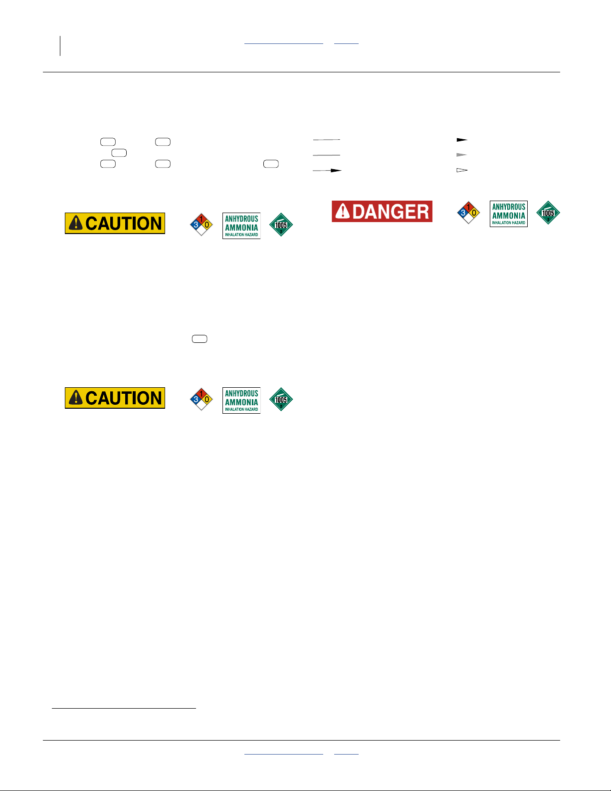
Be Aware of Signal Words
Signal words designate a degree or level of hazard
seriousness.
DANGER, and the color Safety Red, indicate an
imminent hazard which, if not avoided, will result in death
or serious injury. This signal word is limited to the most
extreme situations, typically for machine components
that, for functional purposes, cannot be guarded.
WARNING, and the color Safety Orange, indicate a
potential hazard which, if not avoided, could result in
death or serious injury, and includes hazards that are
exposed when guards are removed. It may also be used
to alert against unsafe practices.
CAUTION, and the color Safety Yellow, indicate a
potential hazard which, if not avoided, may result in
minor or moderate injury. It may also be used to alert
against unsafe practices.
Prepare for Emergencies
▲ Be prepared if a fire starts.
▲ Keep a first aid kit and fire extinguisher handy.
▲ Keep emergency numbers for doctor, ambulance, hospital
and fire department near phone. Know the reporting
requirement for spills or releases of the chemicals you are
using. Have contact numbers available.
▲ For anhydrous ammonia operations, have additional
contact information for:
• national response center
• regional (state) response center
• local response center
▲ If a fire threatens an anhydrous ammonia tank, evacuate the
area. The tank may heat up faster than the relief valve can
vent the rising pressure, resulting in a catastrophic gas
release and possibly an explosion.
417-199M Table of Contents Index 2014-05-14
Page 7

Great Plains Manufacturing, Inc. Table of Contents Index Important Safety Information 3
Be Familiar with Safety Decals
▲ Read and understand “Safety Decals” on page 9,
thoroughly.
▲ Read all instructions noted on the decals.
▲ Keep decals clean. Replace damaged, faded and illegible
decals.
Wear Protective Equipment (PPE)
▲ Wear clothing and equipment appropriate for the job. Avoid
loose-fitting clothing.
▲ Waterproof, wide-brimmed hat
▲ Face shield, goggles or full face respirator.
▲ Prolonged exposure to loud noise can cause hearing
impairment or loss. Wear suitable hearing protection such
as earmuffs or earplugs.
▲ Avoid wearing entertainment headphones while operating
machinery. Operating equipment safely requires the full
attention of the operator.
▲ See manual 407-551M for specific requirements and
recommendations for NH3 PPE.
▲ Goggles with side shields or a full face respirator are
required if handling or applying dusts, wettable powders, or
granules or if being exposed to spray mist.
▲ Cartridge-type respirator approved for pesticide vapors
unless conventional liquid fertilize label specifies another
type of respirator.
▲ Waterproof, unlined gloves. Neoprene is recommended.
▲ Cloth coveralls/outer clothing changed daily; waterproof
items if there is a chance of becoming wet with spray.
▲ Waterproof apron
▲ Waterproof boots or foot coverings
▲ Do not wear contaminated clothing. Wash protective
clothing and equipment with soap and water after each use.
Personal clothing must be laundered separately from
household articles.
▲ Clothing contaminated with certain pesticides must be
destroyed according to state and local regulations. Read
chemical label for specific instructions.
2014-05-14 Table of Contents Index 417-199M
Page 8

4 2013+ NP4000/A/B Table of Contents Index Great Plains Manufacturing, Inc.
Use Safety Chains
(For all nurse tanks)
▲ Use chain with a strength rating equal to or greater than
the gross weight of towed machinery.
▲ Attach nurse tank chain(s) to anchors provided on
applicator. Allow only enough slack in chain for turns.
▲ Replace chain if any links or end fittings are broken,
stretched or damaged.
▲ Do not use safety chain for towing.
▲ Current regulations require two chains on anhydrous
ammonia nurse tank carts.
Avoid High Pressure Fluids
Escaping fluid under pressure can penetrate the skin,
causing serious injury. This fertilizer applicator requires a
Power-Beyond port, which is always under pressure
when the tractor is running.
▲ Avoid the hazard by relieving pressure before disconnecting
hydraulic lines.
▲ Use a piece of paper or cardboard, NOT BODY PARTS, to
check for suspected leaks.
▲ Wear protective gloves and safety glasses or goggles when
working with hydraulic systems.
▲ If an accident occurs, seek immediate medical attention
from a physician familiar with this type of injury.
Minimize Radiation Exposure
The optional DICKEY-john® RVS II and RVS III Radars
are intentional radiators of RF energy. Although its
radiated energy level is far below the limits set by
EN 61010-1:1993 A2:1995-Chapter 12.4, it is advisable
not to look directly into the face of the unit.
The radar must radiate toward the ground and at least
20 cm (8 inches) away from a human during use to
comply with the RF human exposure limits as called out
in FCC 47 CFR Sec.2.1091. DO NOT RE-MOUNT OR
USE THE RADAR IN A MANNER INCONSISTENT
WITH ITS DEFINED USE.
Keep Riders Off Machinery
Riders obstruct the operator’s view. Riders could be
struck by foreign objects or thrown from the machine.
▲ Never allow children to operate equipment.
▲ Keep all bystanders away from machine during operation.
417-199M Table of Contents Index 2014-05-14
Page 9
Great Plains Manufacturing, Inc. Table of Contents Index Important Safety Information 5
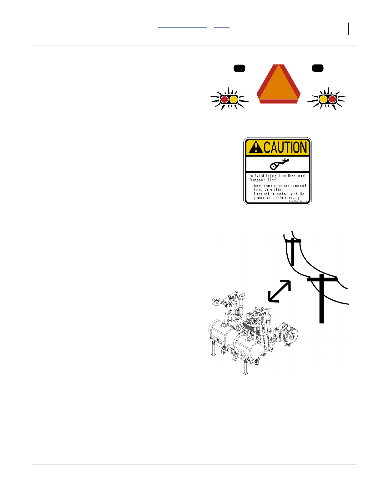
Use Safety Lights and Devices
Slow-moving tractors and towed applicators can create a
hazard when driven on public roads. They are difficult to
see, especially at night.
▲ Use flashing warning lights and turn signals whenever
driving on public roads.
▲ Use lights and devices provided with applicator.
Tires Not a Step
Do not use gauge wheel or lift-assist tires as steps. A tire
could spin underfoot, resulting in a fall onto the applicator
or ground, possibly causing serious injury.
▲ The gauge wheel tires can be in poor ground contact at any
time, even with the fertilizer applicator lowered in the field.
They can appear to be in ground contact, and spin easily, in
multiple conditions.
▲ The lift-assist tires can be in poor ground contact, or out of
ground contact, whenever the fertilizer applicator is
lowered.
Remain Clear of Overhead Lines
▲ If the fertilizer applicator contacts a power line, lethal
voltage may be present on all metal parts. At higher voltage,
the applicator does not need to be in line contact for the
hazard to exist. Maintain at least 10 foot (3 m) clearance.
▲ Electrocution can occur without direct contact between the
energized fertilizer applicator and a person near the
fertilizer applicator.
▲ Watch for sagging, damaged or low electrical lines. The
folded fertilizer applicator could contact lines lower than
13 foot (4 m). Overhead lines at farm structures are a
particular hazard. An incorrectly folded applicator is at risk
from lines lower than 22 foot (7 m).
▲ Watch for all electrical lines during folding and unfolding
operations. Use a spotter during folding and unfolding.
Know the location and height of all lines during transport
and in fields.
▲ If an electrical hazard is observed while on the ground near
the applicator, hop at least 100 feet (30 m) away with both
feet together and summon professional help. At higher
voltage, lethal voltage gradients can also be present at the
soil surface.
▲ Consult your tractor manual for advice on how to respond
to an electrical hazard event while in the cab.
2014-05-14 Table of Contents Index 417-199M
Page 10

6 2013+ NP4000/A/B Table of Contents Index Great Plains Manufacturing, Inc.
Transport Machinery Safely
Maximum transport speed for applicator is 20 mph (32
kph), 13 mph (22 kph) in turns. Some rough terrains
require a slower speed. Sudden braking can cause a
towed load to swerve and upset.
▲ Do not transport an applicator that weighs over 20,000
pounds (9060 kg). Loading liquid fertilizer tanks or
transporting with a nurse tank hitch to the applicator can
easily exceed this limit.
▲ Tow nurse tank separately. Do not tow a nurse tank in train
with the applicator on public roads.
▲ Never park an anhydrous ammonia tank on public roads or
anywhere near sites with high occupancy or high-risk
populations, such as shopping areas, events, schools,
hospitals, retirement communities, etc.
▲ Avoid transporting an anhydrous ammonia tank through
populated areas.
▲ Do not tow a lift-assisted 2-point applicator or nurse tank
that, when fully loaded, weighs more than 1.5 times the
weight of towing vehicle.
▲ Do not transport a 2-point applicator that exceeds the
capacity or ballasting of the tractor. There may not be
enough front wheel traction for safe steering.
▲ Carry reflectors or flags to mark fertilizer applicator in
case of breakdown on the road.
▲ Keep clear of overhead power lines and other obstructions
when transporting. Refer to transport dimensions under
“Specifications and Capacities” on page 154.
▲ Do not exceed 20 mph (32 km/h). Never travel at a speed
which does not allow adequate control of steering and
stopping. Reduce speed if towed load is not equipped with
brakes.
▲ Reduce speed on rough roads.
▲ Comply with national, regional and local laws.
▲ Do not fold or unfold the fertilizer applicator while the
tractor is moving (other than field lift).
417-199M Table of Contents Index 2014-05-14
Page 11

Great Plains Manufacturing, Inc. Table of Contents Index Important Safety Information 7
Handle Chemicals Properly
See manual 407-551M for specific requirements and
recommendations for NH
For Conventional Liquid Materials
Agricultural chemicals can be dangerous. Improper use
can seriously injure persons, animals, plants, soil and
property.
▲ Read and follow chemical supplier instructions.
▲ Wear protective clothing.
▲ Handle all chemicals with care.
▲ Agricultural chemicals can be dangerous. Improper use can
seriously injure persons, animals, plants, soil and property.
▲ Inhaling smoke from any type of chemical fire is a serious
health hazard.
▲ Store or dispose of unused chemicals as specified by the
chemical manufacturer.
▲ If chemical is swallowed, carefully follow the chemical
manufacturer’s recommendations and consult with a doctor.
▲ If persons are exposed to a chemical in a way that could
affect their health, consult a doctor immediately with the
chemical label or container in hand. Any delay could cause
serious illness or death.
▲ Dispose of empty chemical containers properly. By law
rinsing of the used chemical container must be repeated
three times. Puncture the container to prevent future use. An
alternative is to jet-rinse or pressure rinse the container.
▲ Wash hands and face before eating after working with
chemicals. Shower as soon as application is completed for
the day.
▲ Apply only with acceptable wind conditions. Wind speed
must be below 5 mph (8 km/h). Make sure wind drift of
chemicals will not affect any surrounding land, people or
animals.
▲ Never wash out a tank within 100 feet (30 m) of any
freshwater source or in a car wash.
.
3
Shutdown and Storage
▲ Lower fertilizer applicator, put tractor in park, turn off
engine, and remove the key.
▲ Secure fertilizer applicator using locks and supports
provided.
▲ Detach and store fertilizer applicator in an area where
children normally do not play.
▲ Park an anhydrous ammonia applicator downwind of
occupied areas until it is purged of NH3 residues.
▲ Do not leave NH3 nurse tanks unattended.
2014-05-14 Table of Contents Index 417-199M
Page 12

8 2013+ NP4000/A/B Table of Contents Index Great Plains Manufacturing, Inc.
Tire Safety
Tire changing can be dangerous and should be
performed by trained personnel using correct tools and
equipment.
▲ When inflating tires, use a clip-on chuck and extension hose
long enough for you to stand to one side–not in front of or
over tire assembly. Use a safety cage if available.
▲ When removing and installing wheels, use wheel-handling
equipment adequate for weight involved.
Practice Safe Maintenance
▲ Understand procedure before doing work. Use proper
tools and equipment. Refer to this manual.
▲ Work in a clean, dry area.
▲ Lower the fertilizer applicator, put tractor in park, turn off
engine, and remove key before performing maintenance. If
work must be performed with applicator raised, use blocks
or jackstands rated for the fertilizer applicator weight.
▲ Make sure all moving parts have stopped and all system
pressure is relieved.
▲ Allow applicator to cool completely.
▲ Disconnect battery ground cable (-) before servicing or
adjusting electrical systems.
▲ Welding: Disconnect battery ground. Avoid fumes from
heated paint.
▲ Inspect all parts. Make sure parts are in good condition
and installed properly.
▲ Remove buildup of grease, oil or debris.
▲ Remove all tools and unused parts from fertilizer
applicator before operation.
Safety At All Times
Thoroughly read and understand the instructions in this
manual before operation. Read all instructions noted on
the safety decals.
▲ Be familiar with all applicator functions.
▲ Operate machinery from the driver’s seat only.
▲ Do not leave applicator unattended with tractor engine
running.
▲ Do not stand between the moving tractor and applicator
during hitching.
▲ Keep hands, feet and clothing away from power-driven
parts.
▲ Wear snug-fitting clothing to avoid entanglement with
moving parts.
▲ Make sure all persons are clear of working area.
417-199M Table of Contents Index 2014-05-14
Page 13
Great Plains Manufacturing, Inc. Table of Contents Index Important Safety Information 9
Safety Decals
Safety Reflectors and Decals
Your applicator comes equipped with all lights, safety
reflectors and decals in place. They were designed to
help you safely operate your applicator.
▲ Read and follow decal directions.
▲ Keep lights in operating condition.
▲ Keep all safety decals clean and legible.
▲ Replace all damaged or missing decals. Order new decals
from your Great Plains dealer. Refer to this section for
proper decal placement.
▲ When ordering new parts or components, also request
corresponding safety decals.
To install new decals:
1. Clean the area on which the decal is to be placed.
2. Peel backing from decal. Press firmly on surface,
being careful not to cause air bubbles under decal.
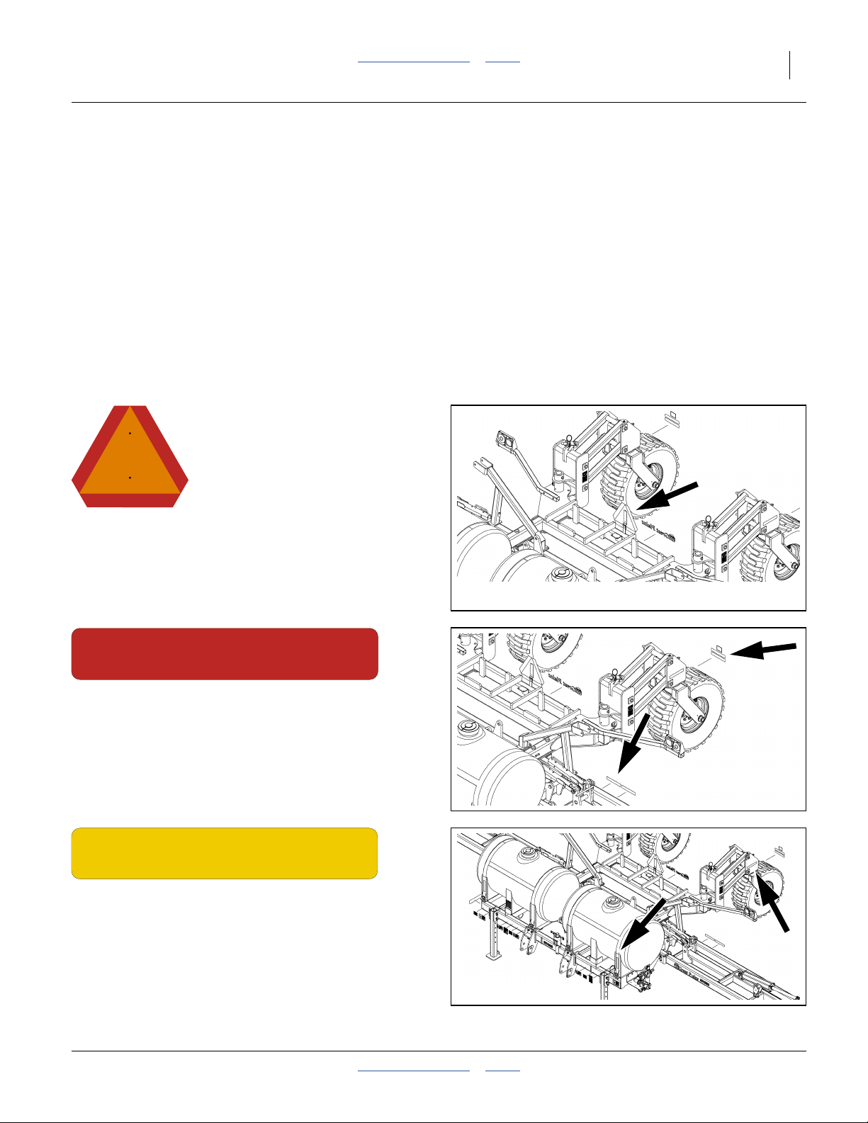
32339
818-055C
Slow Moving Vehicle Reflector
On a mount attached to the transport rest assembly;
1 total
See “Transport” on page 59.
838-266C
Red Reflectors
On the rear face light bracket, and
back face, outside ends of the top transport rest tube;
4 total
See “Transport” on page 59.
838-265C
Amber Reflectors
On outside faces of caster weldments, and on front faces
of outside tank cradles (on tankless models, the forward
reflectors are on the side faces of the front subframe);
4 totalSee “Transport” on page 59.
32339
32339
2014-05-14 Table of Contents Index 417-199M
Page 14
10 2013+ NP4000/A/B Table of Contents Index Great Plains Manufacturing, Inc.
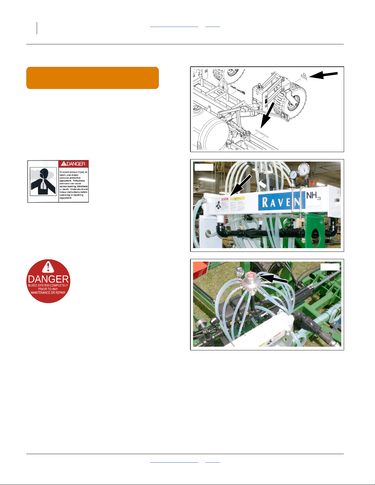
838-267C
Daytime Reflectors
On rear face of caster weldments, below red reflectors,
and on rear face of inner wing weldments near pivot and
outside red reflectors;
4 total
See “Transport” on page 59.
31603
32339
Raven 039-0159-034 (Option) Danger: Ammonia
On front or back side of Raven AccuFlow™;
2 or 4 total
Order replacement from Raven Industries.
115527-01 (Option) Danger: Bleed System
On top of CDS-John Blue Impellicone® flow divider;
1 total
31618
417-199M Table of Contents Index 2014-05-14
Page 15
Great Plains Manufacturing, Inc. Table of Contents Index Important Safety Information 11
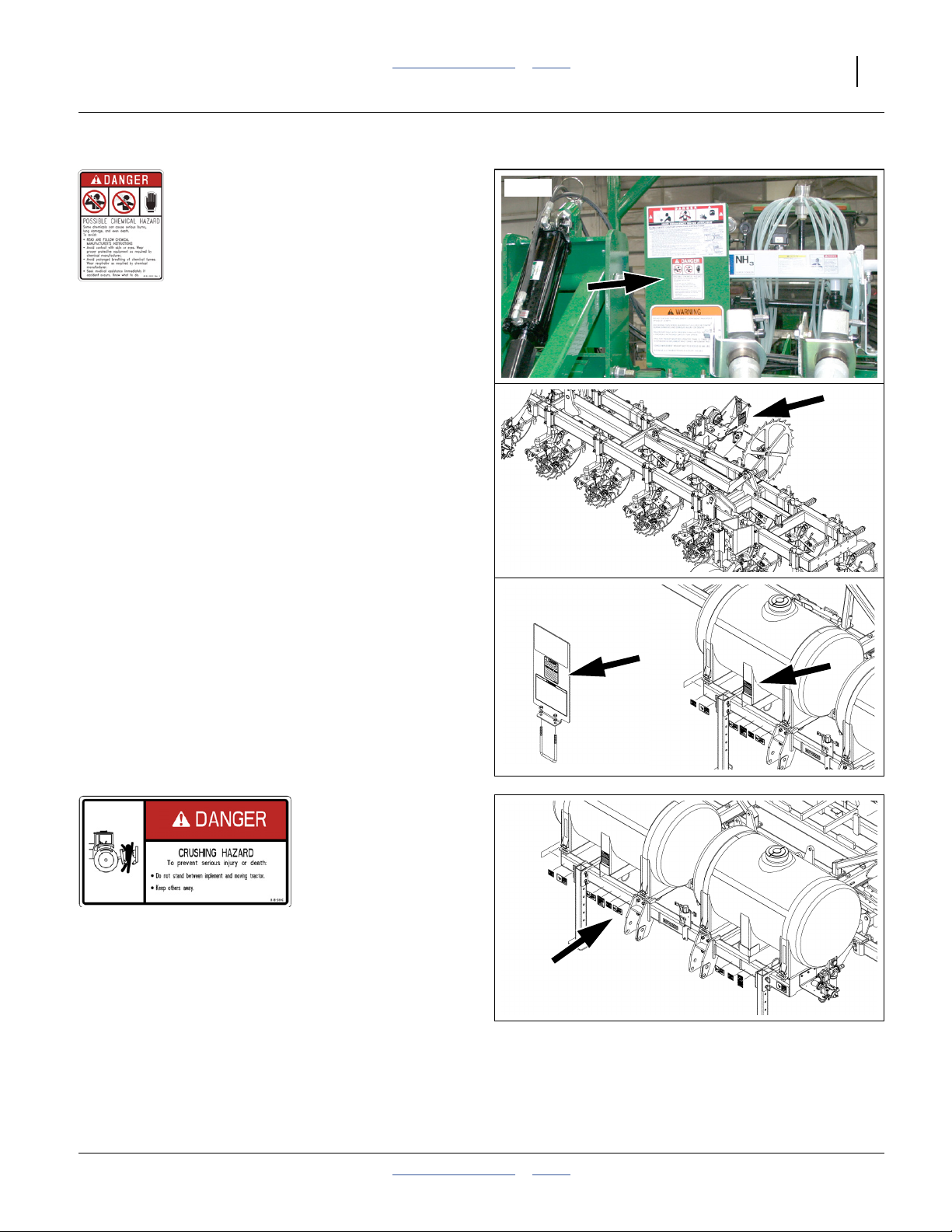
31604
818-323C Danger: Possible Chemical Hazard
NH3 models: On decal mount near Flo-Max™ coupler:
1 total
See “NH3 Operations” on page 61 and separate manual
“Using Anhydrous Ammonia Safely” (407-551M).
Conventional Models: On left face of ground drive pump
mount;
1 total
See “Liquid Operations” on page 74.
Conventional Models: On decal mount at optional rear
hitch and/or on front face of each center tank leg;
1 total
See “Liquid Operations” on page 74.
818-590C Danger: Hitch Crush
On front face of 3-point hitch arms;
2 total
See “Hitching Tractor to Applicator” on page 36.
32344
32339
32339
32339
2014-05-14 Table of Contents Index 417-199M
Page 16

12 2013+ NP4000/A/B Table of Contents Index Great Plains Manufacturing, Inc.
838-599C Danger: Electrocution
On front face of inner wing, near inner pivot;
2 total
See “Remain Clear of Overhead Lines” on page 5.
32339
31529
848-534C (Squibb-Taylor FM125-2000) Danger: Safety Coupler (Option)
On decal mount near Flo-Max™ coupler;
1 total
This decal summarizes the mechanical procedure for
coupler re-connection after a breakaway event. Rely on
these instructions only if the Squibb-Taylor Flo-Max™
manual is not available. See “NH3: Breakaway Event”
on page 71.
818-337C Warning: Speed
On front of front cross tube right of hitch;
1 total
See “Transport” on page 59.
32339
417-199M Table of Contents Index 2014-05-14
Page 17

Great Plains Manufacturing, Inc. Table of Contents Index Important Safety Information 13
818-437C Warning: High Pressure Fluid
On front face front frame at right end, and on left and
right faces of parallel arm mounts;
5 total
See “Hitching Tractor to Applicator” on page 36.
32339
31946
818-860C Warning: Moving Parts (Option)
On left face ground drive pump mount;
1 total
848-551C Warning: Towing
On decal mount near Flo-Max™ coupler:
1 total
See “Transport” on page 59 and “Liq: Hitching
Conventional Nurse Tank” on page 76 for further
information.
31604
2014-05-14 Table of Contents Index 417-199M
Page 18
14 2013+ NP4000/A/B Table of Contents Index Great Plains Manufacturing, Inc.
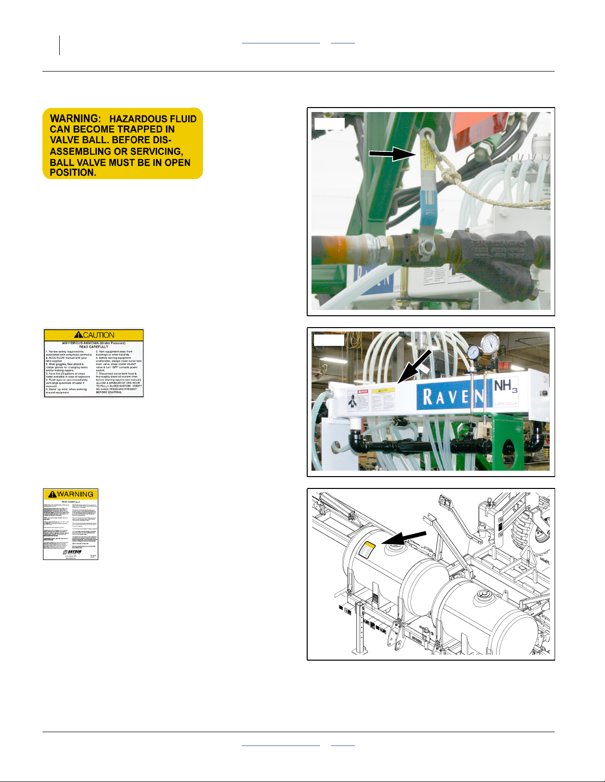
31528
(no part number) Warning: Ball Valve (Option)
This decal should not apply to 2013+ NP4000A
applicators, but might be encountered on nurse tank
valves, or if repairs are made with old-stock after-market
parts. See “Avoid Ball Traps” on page 117.
Older unvented ball valves can trap fluid inside the ball if
closed with the line fully charged. Great Plains ball
valves shipped in 2011 and later have a bleed orifice on
the downstream side of the valve ball and do not require
this decal.
Raven 039-0159-035 Caution: Ammonia (Option)
On front or back side of Raven AccuFlow™;
2 or 4 total
Order replacement from Raven Industries.
Snyder 977176 Warning: Tank Safety (Option)
On upper front face of each tank:
0 or 2 total
Replacement decals available from Snyder Industries:
www.snydernet.com
See “Liquid Operations” on page 74.
31603
32339
417-199M Table of Contents Index 2014-05-14
Page 19
Great Plains Manufacturing, Inc. Table of Contents Index Important Safety Information 15
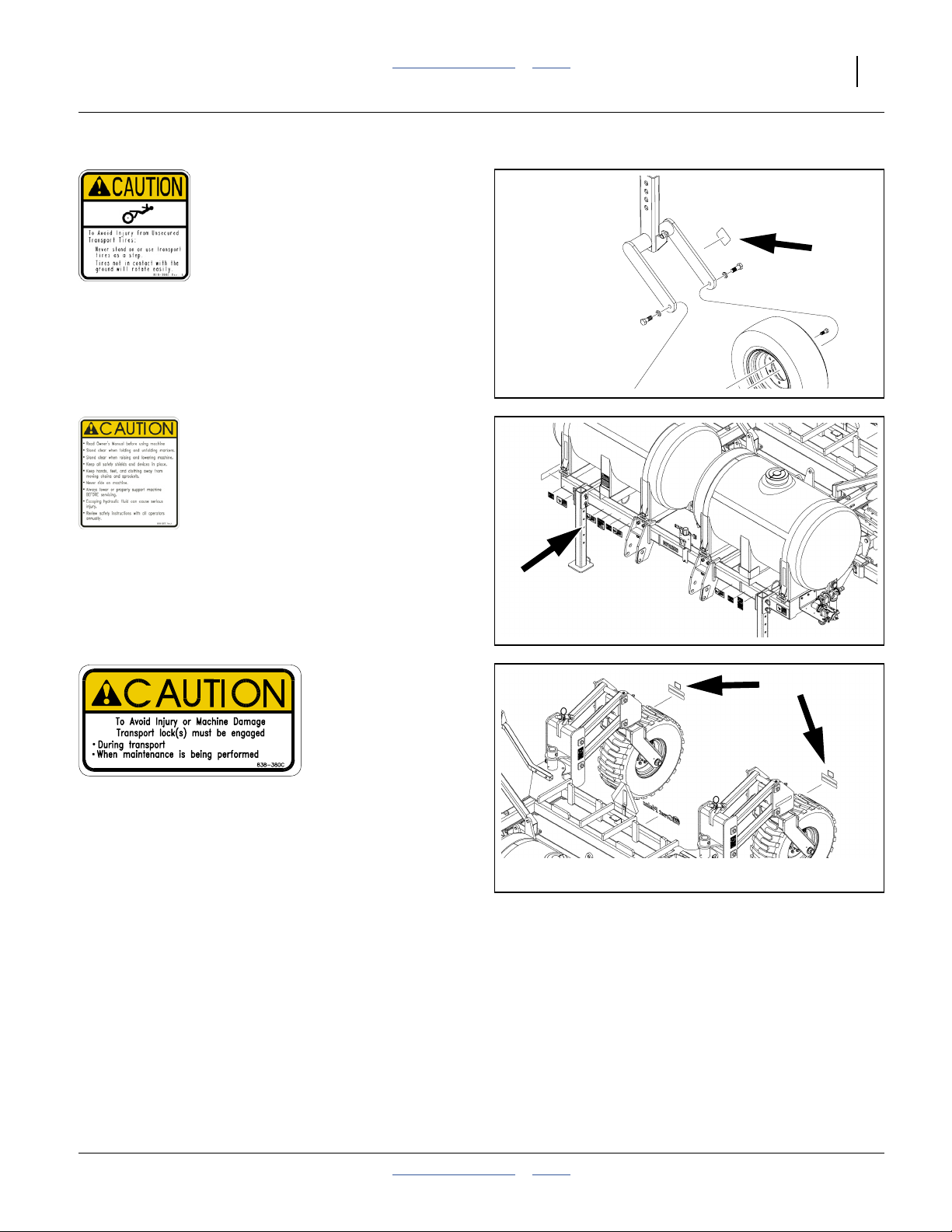
818-398C Caution: Tires Not A Step
On outside face of caster arms above tires;
2 total
See “Tires Not a Step” on page 5.
32318
818-587C Caution: General
On front of front frame tube right of hitch;
1 total
See “Important Safety Information” on page 1.
838-380C Caution: Transport Locks
On rear face of caster weldments, above red reflectors;
2 total
See “Important Safety Information” on page 1.
32339
32339
2014-05-14 Table of Contents Index 417-199M
Page 20
16 2013+ NP4000/A/B Table of Contents Index Great Plains Manufacturing, Inc.
CAUTION
To Avoid Injur y or Machine Damage from Improper Tire
Inflation or Torquing of Wheel Bolts:
Maintain transport tire inflation pressure between 100 psi
and 105 psi. Maximum inflation pressure is 105 psi.
Torque transport wheel bolts to 170 ft-lb.
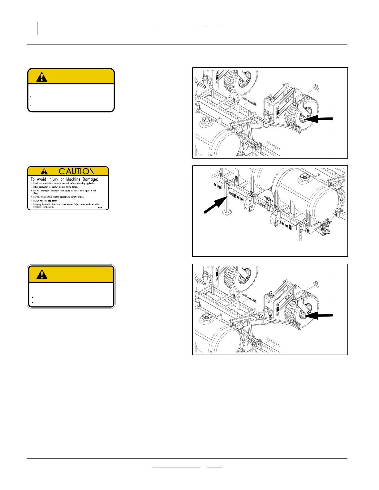
838-890C Caution: Tire Pressure and Torque
On rim of each NP4000B lift assist wheel;
2 total
See “Tire Safety” on page 8.
838-890C
32339
848-736C Caution: Applicator
On front of front frame tube right of hitch;
1 total
See “Liquid Operations” on page 74.
CAUTION
To Avoid Injur y or Machine Damage from Improper Tire
Inflation or Torquing of Wheel Bolts:
Maximum inflation pressure of tires is 80 psi.
Torque wheel bolts to 300 lb-ft.
848-801C Caution: Tire Pressure and Torque
On rim of each NP4000 or NP4000A lift assist wheel;
2 total
See “Tire Safety” on page 8.
848-801C
32339
32339
417-199M Table of Contents Index 2014-05-14
Page 21

Great Plains Manufacturing, Inc. Table of Contents Index Important Safety Information 17
31599
848-539C General Safety: First Aid Water (Option)
On left and right sides of the wash water tank;
2 total
See “Ammonia Emergency Action” in the “Using
Anhydrous Ammonia Safely” manual (407-551M), and
“Wash Water (NP4000A)” on page 47.
2014-05-14 Table of Contents Index 417-199M
Page 22

18 2013+ NP4000/A/B Table of Contents Index Great Plains Manufacturing, Inc.
Introduction
Great Plains welcomes you to its growing family of new
product owners. Your Nutri-Pro® 40-Foot Fertilizer
Applicator (NP4000 or NP4000A) has been designed
with care and built by skilled workers using quality
materials. Proper setup, maintenance, and safe
operating practices will help you get years of satisfactory
use from the machine.
Description of Unit
The NP4000/A/B is an applicator implement for
conventional liquid fertilizer, anhydrous ammonia (NH
or both. It has a working width (swath) of 36 or 40 feet
(11 or 12.2 m). The applicator has single or triple
coulters with tines for sub-soil application from optional
on-board or user-provisioned tanks.The NP4000/A/B has
a lift-assisted 2-point hitch.
When configured for conventional liquid fertilizer, the
NP4000 model is designed for use with
an optional ground-drive CDS-John Blue® piston pump,
an optional variable-rate Ace hydraulic drive pump, or
a user-provisioned pump.
When configured for anhydrous ammonia the NP4000A
model relies on NH3 vapor pressure from a separately
provisioned trailing nurse tank.
A Raven SCS 450 console is available for sectional and
variable-rate control.
Models Covered
This manual applies to 2013 and later (2013+)
Great Plains applicator models:
Conventional Liquid Fertilizer Models
NP4000-1630 16-row 30-inch (76.2 cm)
NP4000-1630+SD 17-row (16-row Side Dress)
Anhydrous Model (configurable for two materials)
NP4000A-16C30 16-row 30-inch (76.2 cm)
NP4000A-16C30+SD 17-row (16-row Side Dress)
NP4000B-1238 12-row 38 inch (96.5 cm) bedded
NP4000B-1240 12-row 40-inch (102 cm) bedded
Intended Usage
Use the NP4000/A/B Fertilizer Applicator only to apply
compatible fertilizers. Do not modify Great
Plains-provisioned components, or install
user-provisioned components, except as authorized or
recommended by Great Plains.
)
3
Figure 1
NP4000A Fertilizer Applicator
34950
Document Family
417-199M 2013+ NP4000/A/Ba Operator/Rate
Manual
(this document)
417-199P NP4000/A/B Parts manual
417-199Q NP4000/A/B Pre-Delivery manual
Manuals for Options:
407-551M Using Anhydrous Ammonia Safely
12-M-29 CDS-John Blue® IP-1300/1800
Impellicone® parts
016-0159-403 Raven AccuFlow™ Operator manual
016-0159-831 Raven SCS 450 Installation, Operation
and Service manual
FVC062 Squibb-Taylor Flo-Max™ manual
016-0159-831 Raven SCS 450 Installation, Operation
and Service manual
12-M-43 CDS-John Blue NGP Pump Parts and
Instructional manual
HYD-MAN
b
Ace Pump Instruction manual
a. For 2012- NP4000, see manual 407-776M.
For NP3000/A, see manual 407-613M.
For NP30A and NP40A, see manual 407-502M.
For NP30L and NP40L, see manual 407-313M.
b. Available from Ace Pump Corporation:
http://www.acepumps.com
417-199M Table of Contents Index 2014-05-14
Page 23

Great Plains Manufacturing, Inc. Table of Contents Index Introduction 19
Using This Manual
This manual familiarizes you with safety, assembly,
operation, adjustments, troubleshooting, and
maintenance. Read this manual and follow the
recommendations to help ensure safe and efficient
operation.
The information in this manual is current at printing.
Some parts may change to assure top performance.
“Option” refers to components not part of the standard
product, and not “optional” steps. If the component is
installed, the instructions apply.
Identifies an Economic (not a Safety) Risk:
NOTICE provides a crucial point of information related to the
current topic. Read and follow the instructions to avoid damage
to equipment and ensure desired field results.
Note: This form sets off useful information about the
current topic, or forestalls possible
misunderstanding.
Right-hand and left-hand as used in
this manual are determined by facing
the direction the machine will travel
while in use unless otherwise stated.
An orientation rose in some line crt
illustrations shows the directions of:
Up, Back, Left, Down, Front, Right.
R
F
U
B
L
D
1
Single-digit and single-letter callouts refer to local
illustrations. The callout numbers/letters may be
re-used for different items on other pages.
A00
Two-digit callouts in the range to and to
L00
L51
refer to the same tank and Nutri-Pro®plumbing
A11 A86 L11
system components throughout this manual. “A00”
references are for Anhydrous. “L00” references are
for conventional Liquid.
12 12
Callouts and above refer to parts of Options
(see Appendix C).
2014-05-14 Table of Contents Index 417-199M
Page 24
20 2013+ NP4000/A/B Table of Contents Index Great Plains Manufacturing, Inc.
Owner Assistance
If you need customer service or repair parts, contact a
Great Plains dealer. They have trained personnel, repair
parts and equipment specially designed for Great Plains
products.
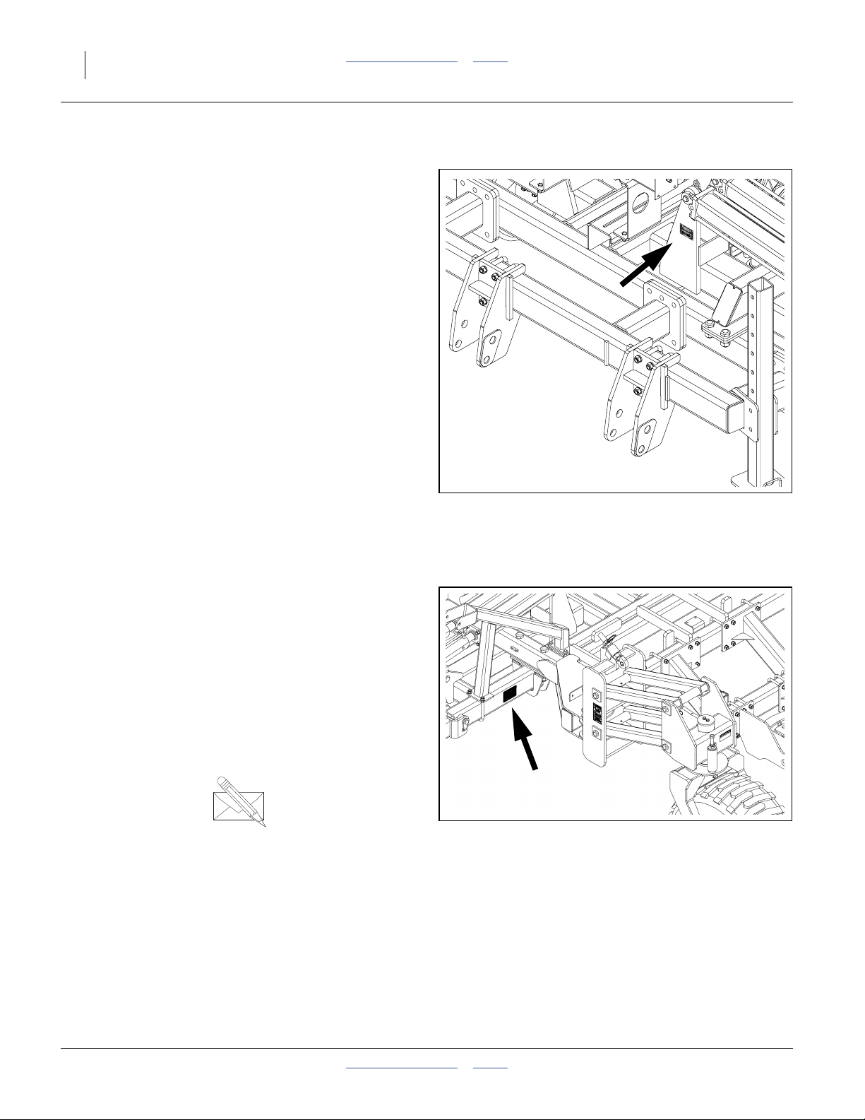
Refer to Figure 2 or Figure 3
Your machine’s parts were specially designed and
should only be replaced with Great Plains parts. Always
use the serial and model number when ordering parts
from your Great Plains dealer.
For 2013 and later applicators, the serial number plate is
located on the center section, on the front face of the left
front fold cylinder mount.
For 2012 and earlier applicators, the serial-number plate
is located on the rear face of the center frame, ahead of
the left caster pivot.
Record your fertilizer applicator model and serial number
here for quick reference:
Model Number:__________________________
Serial Number: __________________________
Your Great Plains dealer wants you to be satisfied with
your new machine. If you do not understand any part of
this manual or are not satisfied with the service received,
please take the following actions.
1. Discuss the matter with your dealership service
manager. Make sure they are aware of any problems
so they can assist you.
2. If you are still unsatisfied, seek out the owner or
general manager of the dealership.
For further assistance write to:
Figure 2
2013+ Serial Number Location
M NP40A-25S20
36030
Product Support
Great Plains Mfg. Inc., Service Department
PO Box 5060
Salina, KS 67402-5060
Figure 3
gp_web_cs@greatplainsmfg.com
2012- Serial Number Location
785-823-3276
417-199M Table of Contents Index 2014-05-14
32348
Page 25
Great Plains Manufacturing, Inc. Table of Contents Index 21
Application Overview
Legend:
Tank, plumbing and setup requirements differ for
anhydrous (A) and conventional systems (L). The next
few pages provide an overview of both systems.
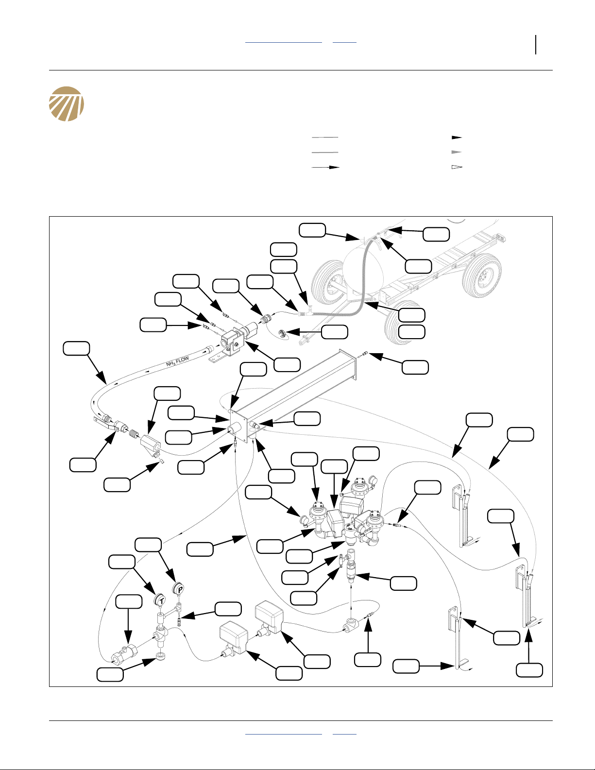
Anhydrous: System Components
Single-Cooler Section Control Configuration - see
page 160 through page 164 for alternates.
Callout numbers A11 through A86 identify the same
applicator and tank components throughout this manual.
Liquid NH
NH3 Vapor Vapor Flow
Direction of Flow Exception Flow
3
Liquid Flow
A17
A18
A20
A15
A16
A19
A13
A21
A22
A34
A12
A57
A47
A42
A60
A61
A14
A24
A56
A47
A40
A11
A39
A67
A65
A58
A59
A23
A48
A48
A44
A43
A45
A27
A25
A28
A33
A29
A41
A38
A37
A36
A35
A45
A31
A26
Anhydrous Ammonia (NH3) Plumbing (Single-Cooler w/ Section Control)
2014-05-14 Table of Contents Index 417-199M
A30
Figure 4
A32
A46
A49
34958
Page 26
22 2013+ NP4000/A/B Table of Contents Index Great Plains Manufacturing, Inc.
NH3 System Narrative
This list describes a single-cooler anhydrous system with
section control. A dual-cooler system has two of
components through , and two additional
dual-tube tines . A single-section system lacks
components through and has only one of .
A11 A24
A49
A35 A39 A40
Legend:
Liquid NH
3
Liquid Flow
NH3 Vapor Vapor Flow
Direction of Flow Exception Flow
Refer to Figure 6 on page 29
A11.Acme cap
Suffocation, Blinding and Burning Hazards:
See “NH3: Safing Applicator Before Cart Hitch” on
page 61, for safe opening procedure.
This captive cap protects the inlet when no nurse
tank is connected. NH3might be sealed behind this
cap.
A12.Acme inlet
The nurse tank hose coupler connects here and
A57
must have 13⁄4-4 female Acmeaswivel coupler. See
page 64 for nurse tank connection.
A13.Coupler Inlet Bleed Valve
Suffocation, Blinding and Burning Hazards:
See “About Bleed Valves:” on page 38.
This fitting is carefully opened at normal and
abnormal disconnects, to bleed NH3 liquid and
vapor from the hoses (or to bleed just the nurse tank
hose upon breakaway). It is also opened prior to
Acme cap removal to verify that the line is
discharged. See “NH3: Making Nurse Tank
Connections” on page 64, “NH3: Unhitching
Nurse Tank” on page 73 and “NH3: Breakaway
Event” on page 71.
A14.Breakaway Coupler
Upon Event: Probable Chemical Hazard:
See “NH3: Breakaway Event” on page 71.
This assembly is designed to separate and seal the
lines if between 300 to 400 pounds of pull force is
applied to the nurse tank hose. In normal
operations, this does not happen.
Should the hitch fail, and both safety chains fail, or
an operator makes serious basic safety errors, the
breakaway separates to protect the hoses from
rupture. Spring-loaded checks inside the breakaway
seal both ends of the now-broken connection. If the
line was charged, 60 cc of liquid NH3is released on
breakaway.
Resetting a parted breakaway coupler is a complex
operation requiring tools. Consult the breakaway
manual for details. More significant matters are
safing the applicator and nurse tank, then correcting
the cause of the breakaway. See “NH3: Breakaway
Event” on page 71.
A15.Breakaway Hydrostatic Relief Valve
In normal operation, this valve does not activate.
It is designed to open at 375 psi, well above the
250-265 psi operating pressure of the nurse tank’s
main pressure relief valve.
Operator action is periodic inspection, and to
replace this hydrostatic relief valve, a time-dated
part, when it reaches the end of its operating life
(see page 124). See “Hydrostatic Relief Valve
Maintenance” on page 122 for maintenance.
Valve function: when operating valves are closed on
both sides of the breakaway (or on just the
applicator side upon a breakaway event), NH3 can
be trapped in the breakaway coupler. As the NH
warms, it could create dangerously high pressure.
This relief valve opens to vent excess pressure.
3
a. Acme refers to the ANSI/ASME B1.5-1997 screw thread, which has a trapezoidal thread profile.
417-199M Table of Contents Index 2014-05-14
Page 27

Great Plains Manufacturing, Inc. Table of Contents Index Application Overview 23
A16.Coupler Outlet Bleed Valve
Suffocation, Blinding and Burning Hazards:
See “About Bleed Valves:” on page 38.
This fitting is kept closed in normal operations.
When the breakaway is properly coupled, the inlet
bleed valve bleeds the entire assembly, and
A13
applicator supply hose. On breakaway, this valve is
used to bleed the applicator side of the
disconnection. See “NH3: Breakaway Event” on
page 71.
A17.Supply Hose
This connects the breakaway coupler to the
emergency shut-off valve. Operator action is to
replace this hose, a time-dated part, when it
reaches the end of its operating life (see page 124).
A18.Emergency Shut-off Valve
The handle of this is valve has a rope which is
routed to the tractor cab (see page 38). Closing this
valve stops NH3flow to the cooler, metering system
and tines. There can still be a substantial amount of
NH3 in the system, for some time, with this valve
closed. See the “Using Anhydrous Ammonia
Safely” manual (407-551M) for emergency
operation.
A19.Strainer
This filter contains a 20 mesh screen and two
ceramic magnets to remove debris from the NH
flow.
A20.Strainer Magnets
These capture ferrous metal debris of any size.
They need to be cleaned every 4 to 5 tank loads.
See page 127.
A21.AccuFlow™ Super Cooler (Heat Exchanger)
For effective application, NH3needs to remain in the
liquid state until released underground. This is
accomplished by refrigeration. Some of the flow is
tapped , fed back to the cooler at , vaporized
and used to chill the fluid passing from to .
A32 A34
A22 A24
A22.Cooler Intake
Liquid NH
enters the cooler here.
3
A23.Cooler Hydrostatic Relief Valve
In normal operation, this valve never activates. NH
3
can get trapped in the system between the
emergency shut-off valve and the On/Off
A31
valve , if both valves are closed while the system
A18
is charged. As the liquid warms and pressure rises,
this valve protects the system with periodic
releases.
This valve is set to activate at 350 psi, higher than
the nurse tank’s relief valve.
Operator action is periodic inspection, and to
replace this hydrostatic relief valve, a time-dated
part, when it reaches the end of its operating life
(see page 125). See “Hydrostatic Relief Valve
Maintenance” on page 122 for maintenance.
A24.Cooler Outlet
Chilled liquid NH3 exits the cooler here.
A25.Flow Meter
This fitting converts fluid flow to pulses for the
SCS 450 controller. It has a range of 1-60 gpm. A
tag on the cable lead provides a “METER CAL”
number specific to the installed meter (and accurate
only for NH3 fluid flow, and not NH3 vapor flow).
A26.Drain Cap
The plumbing cross and lower cap below the
temperature gauge are provided to allow the gauge
3
probe to be exposed to the full NH3 stream. This
cap does not require periodic clean-out.
A27.Temperature Gauge
This gauge reports the temperature of the chilled,
flowing, NH3. When NH3 is not flowing, this gauge
slowly drifts up to ambient temperature.
Checking the temperature and pressure gauges
A28
against the chart in the “Using Anhydrous
Ammonia Safely” manual (407-551M), or in the
Raven AccuFlow™ manual, indicates whether the
flowing NH3 is in a liquid state.
Normal field temperatures of the chilled flowing NH
3
are in the range 20 to 83°F (-7 to 28°C).
2014-05-14 Table of Contents Index 417-199M
Page 28

24 2013+ NP4000/A/B Table of Contents Index Great Plains Manufacturing, Inc.
A28.Pressure Gauge
This gauge reports the pressure of the NH
exits the cooler. If line valves are closed, a pressure
reading above zero indicates NH
between the emergency shut-off valve and the
On/Off solenoid valve (the Control Valve
A31 A30
is present
3
A18
does not completely close).
Checking the pressure and temperature against
the chart in the “Using Anhydrous Ammonia
Safely” manual (407-551M), or in the Raven
AccuFlow™ manual, indicates whether the flowing
NH3 is in a liquid state.
When valves are open but NH3 is not flowing, this
gauge normally reads within 5 psi of the nurse tank
pressure gauge . If they are materially different
A67
at zero flow, one of the gauges may be defective.
When NH3 is flowing, the pressure reported by this
gauge is lower than the tank pressure.
A28
A29.Cooler Bleed Valve
Suffocation, Blinding and Burning Hazards:
See “About Bleed Valves:” on page 38.
This valve is normally closed. It is used to bleed
trapped NH3 from the cooler system when valves
are closed. It can also be used to accelerate
clearing the cooler system for maintenance.
A30.Control Valve
This is a variable electronic valve controlled by the
SCS 450. It is the primary control point for
application rate. When power is off, this valve
remains at its most recent setting.
This valve has a visible indicator above the valve
ball casing, indicating whether open, closed or in
between.
When commanded to a rate of zero, this valve does
not completely close. Use shut-off valves to
completely stop flow. A full slew from fully open to
minimum takes approximately 9 seconds.
A27
after it
3
A31.Master Shut-Off Valve
This is the normal control for starting and stopping
total application flow in the field (for turns, etc.). This
component is an open/close solenoid valve
controlled by the “MASTER” switch on the SCS 450.
When power is off, this valve remains at its most
recent setting.
This valve has a visible indicator above the valve
ball casing, indicating whether open or closed.
Operation of this valve is essentially instantaneous.
Its valve ball is equipped with a downstream relief
orifice.
A32.Refrigerant Tap
A small amount of the NH3flow is taken at this point
to provide refrigeration at the cooler. There are no
operational items for this fitting.
A33.Refrigerant Line
This tubing passes tapped refrigerant NH3 to the
cooler. Operator action is to replace this tubing,
a time-dated part, when it reaches the end of its
operating life. See page 125.
A34.Cooler Refrigerant Inlet
Tapped refrigeration flow enters the cooler at this
fitting, and is vaporized to chill the liquid entering at
A22
fitting . There are no operational items for this
fitting.
A35.Section Control Check Valve
(Section Control Option Only)
This prevents back flow when section shut-off
valves are off with NH3 present. There are no
A39
operational items for this fitting.
A36.Section Control Bleed Valve
Suffocation, Blinding and Burning Hazards:
See “About Bleed Valves:” on page 38.
(Section Control Option Only)
This valve is normally closed. It is used to bleed
trapped NH3 from the section control system if all
section valves are closed.
A39
417-199M Table of Contents Index 2014-05-14
Page 29

Great Plains Manufacturing, Inc. Table of Contents Index Application Overview 25
A37.Section Control Relief Valve
(Section Control Option Only)
In normal operation, this valve never activates.
NH3can get trapped in the system between the
section control check valve and the section
shut-off valves , if all section valves are closed
A39
A35
while the system is charged. As the liquid warms
and pressure rises, this relief valve protects the
system with periodic releases.
This valve is set to activate at 350 psi.
Operator action is periodic inspection, and to
replace this hydrostatic relief valve, a time-dated
part, when it reaches the end of its operating life
(see page 125). See “Hydrostatic Relief Valve
Maintenance” on page 122 for maintenance.
A38.Section Flow Divider
(Section Control Option Only)
This is a CDS-John Blue®Impellicone® manifold.
It evenly splits the NH3 flow for distribution through
the row flow dividers . There are no operational
A40
items for this component.
A39.Section Shut-Off Valves
(Section Control Option Only)
These are the normal controls for suspending
per-section application flow in the field (for point
rows, pass overlap, etc.). These are open/close
solenoid valves controlled by the “BOOMS”
switches on the SCS 450.
When used with the SCS 450 or other suitable
sectional application controller, shutting off a
section causes the total flow to be reduced by1⁄3of
the all-sections-on rate, keeping the rate constant
for the section(s) still active.
Each section valve has a visible indicator above the
valve ball casing, indicating whether open or closed.
Operation of each section valve is essentially
instantaneous. However, there is considerable
residual NH3in the section flow divider and delivery
tubes after shut-off. When console power is off, the
valves remain at their most recent setting.
The valve balls are equipped with a downstream
relief orifice.
A40.Row Flow Divider(s)
This is a CDS-John Blue®Impellicone® manifold. It
evenly splits the NH3 flow for distribution through
the delivery tubes . There are no operational
A45
items for this component.
A41.Flow Divider Manifold Inlet
NH3 liquid flow enters the flow divider here.
A42.Flow Divider Pressure Gauge
This gauge reports the pressure prior to flow
division. It normally reads lower than the cooler and
nurse tank pressure gauges.
A43.Flow Divider Outlet
Each of these ports receives an equal fraction of the
NH3 liquid flow.
A44.Flow Divider Plug
Unused ports are plugged with a steel NPT plug.
Unused ports do not affect flow balance at the other
ports.
A45.Delivery Tube
This tubing passes NH3 liquid flow to the tines.
Operator action is to replace this tubing, a
time-dated part, when it reaches the end of its
operating life. See page 126.
A46.Coulter Tine (Single)
Tines inject the liquid NH3. All but two (or four) of
the rows are equipped with tines having a single
smaller liquid delivery tube. Tines need frequent
inspection for wear and damage.
A47.Cooler Vapor Outlets (2)
Two vapor outlets direct the now-gaseous
refrigerant flow (that entered at ) to two special
A49
tines per cooler.
A34
A48.Vapor Tube
This tubing passes NH3vapor flow to the dual tines.
Operator action is to replace this tubing,
a time-dated part, when it reaches the end of its
operating life. See page 126.
A49.Coulter Tine (Dual)
There are two of these special tines per cooler (four
total on a dual-cooler applicator). They direct the
vaporized refrigerant NH3 gas into the soil at the
larger rear vapor tube. They are otherwise identical
to the single-tube tines .
A46
2014-05-14 Table of Contents Index 417-199M
Page 30

26 2013+ NP4000/A/B Table of Contents Index Great Plains Manufacturing, Inc.
The following callouts are for trailing nurse tank cart
components. See the “Using Anhydrous Ammonia
Safely” manual (407-551M) for all nurse tank callouts
A51 A86
( - ). The present manual lists only those required
for applicator field operations.
A56.Acme Parking Plug
A threaded stud (or other means) for storage of the
outlet hose when not coupled to the applicator.
Excess NH3 Release Hazard:
If the outlet hose is entirely dismounted (both ends free)
for transport and storage, and both ends are 13⁄4-4 Acme,
be sure about which end is which. Installing a hose
backwards can result in needless excess NH
release at
3
unhitching, or a line segment unprotected by bleed
and/or relief valves.
A57.Acme Female Hose Coupler
This end of the hose connects the tank withdrawal
A63 A12
valve to the leading applicator inlet at the
breakaway coupler. For use with a Nutri-Pro
®
applicator, the outlet end of the hose must be
equipped with a 13⁄4-4 female Acme fitting.
The outlet end of the hose has a swivel collara or
shroud containing the female Acme fitting. This
allows connection without needing to twist the hose.
Acme hose couplers are intended for hand
tightening only. Do not use tools to make the
cart-applicator connection. A liquid-tight seal is
made by the gasket in the male Acme fitting on the
applicator break-away coupler.
For dual-tank carts, each tank usually has its own
hose.
A58.Outlet Hose Assembly
The hose may have zero, one or two operating
valves , one or more bleed valves , and a
hydrostatic relief valve . The outlet end may
A60 A61
A62
have an Acme. plug.
Hose valves are typically hand wheel valves, or
lever valves. Read any documents provided for the
valves. Have the terminal or dealer explain how the
valves work.
Suffocation, Blinding and Burning Hazards:
Never test an anhydrous ammonia hose valve unless you
are absolutely certain the hose and valve bodies are
empty, or both hose ends are securely connected to
sealed systems.
▲ A two-valve hose can contain a substantial amount of
NH
even when completely disconnected. See “Avoid
3
Line Traps” on page 116.
▲ Older ball valves can contain NH3 inside the ball
when closed, even though disconnected at both ends.
See “Avoid Ball Traps” on page 117.
Follow instructions for bleeding and checking. Never use
a valve handle as a carrying handle. Keep hands clear of
bleed valves when carrying a hose.
A59.Nurse Tank Hose Body
NH3 hoses are time-dated components. Operator
action is to replace the assembly when it
A58
reaches the end of its operating life.
A60.Hose Valve(s)
The hose may have zero, one or two operating
valves .
A60
Excess NH3 Release and Trapping Hazards:
Understand hose and tank withdrawal valve functions
and sequencing. This manual presumes a hose with a
single outlet-end shut-off valve , and a tank outlet
with a withdrawal valve . If the hose in use is
A60
A65
different, have the hose provider explain the correct
order for operations.
a. Acme collars may be aluminum, but all internal coupler components must be NH3-safe, typically stainless steel.
417-199M Table of Contents Index 2014-05-14
Page 31

Great Plains Manufacturing, Inc. Table of Contents Index Application Overview 27
A61.Bleed Valve(s)
Suffocation, Blinding and Burning Hazards:
See “About Bleed Valves:” on page 38.
Hose valves typically have bleed valves. Have the
hose provider explain exactly what is bled by each
bleed valve.
The purpose of a bleed valve is to perform a
controlled release, via an orifice, of any fluid or gas
trapped in the closed line prior to disconnect at a
nearby Acme fitting.
A single bleed valve may be located on the inlet or
outlet side of the valve, and only protects that side
of the circuit when the valve is closed. More rarely, a
shut-off valve has bleed valves on both sides of the
valve. An older ball valve may have a bleed valve for
the ball itself.
A65.Withdrawal Valve
In field operations, this valve is
opened first, and
closed first.
Ammonia Release Hazard:
Never open the withdrawal valve unless:
a. all other valves and bleed valves, are closed, or;
b. the applicator is configured and ready for use.
Always be on the up-wind side for valve operation.
Always open slowly.
Always check for signs of release when opening this
valve.
The withdrawal valve is the application outlet valve.
It is usually located on the tank top, but may be
located on the bottom. It is color coded red or
orange.
A67.Pressure Gauge
This gauge reports the pressure (usually in psi) of
the NH3 gas at the top of the tank. The reading
varies with tank and ammonia temperature.
2014-05-14 Table of Contents Index 417-199M
Page 32

28 2013+ NP4000/A/B Table of Contents Index Great Plains Manufacturing, Inc.
Conventional Liquid: Applicator System Components
Hydraulic Drive System Components (Options)
See page 30 to page 32 for callout descriptions.
L13
L14
L13
L12
L15
L14
L18
L11
L27
L36
L28
L38
L39
L29
L30
L37
L31
L32
L41
L40
L17
L16
L33
L35
L34
L42
L43
Figure 5
Options: Hydraulic Drive Plumbing with On-Board Tanks, Boom and Coulter Attachment
417-199M Table of Contents Index 2014-05-14
34963
Page 33

Great Plains Manufacturing, Inc. Table of Contents Index Application Overview 29
Ground Drive System Components (Options)
See page 30 to page 32 for callout descriptions
L12
L11
L24
L23
L13
L22
L25
L26
L14
L14
L13
L15
L41
L16
L18
L19
L17
L20
L21
L33
L35
L36
L34
L38
L37
L43
L39
L40
L42
Figure 6
Options: Ground Drive Plumbing with On-Board Tanks, Boom and Coulter Attachment
2014-05-14 Table of Contents Index 417-199M
34964
Page 34

30 2013+ NP4000/A/B Table of Contents Index Great Plains Manufacturing, Inc.
Liquid System Narrative
Tank, plumbing and setup requirements differ for ground
drive and hydraulic drive applicators. The next few pages
provide an overview of both systems.
Refer to Figure 6 on page 29 and Figure 5 on page 28
Note: Callouts L11 to L51, correspond to the items
beginning below, and identify the same
components throughout this manual.
This list presumes that the applicator has system
components factory-installed by Great Plains. The list
includes all components for either the preset or hydraulic
drive pumping system.
If the applicator has aftermarket components, part or all
of this information may not apply to your operations.
Consult the manual or other documentation for your tank
or pump.
L11. Application Tank
Tank Option: The system depicted shows the
optional twin 300 gallon tanks, which includes the
quick-fill inlet assembly. A user-provisioned fertilizer
supply tank may be a trailing nurse tank cart, or may
be tractor-mounted.
A trailing nurse tank cart requires the optional nurse
tank hitch (page 145) on the applicator. The cart
must be full-trailering, and not semi-mounted. The
Great Plains plumbing systems are not
pre-configured for user-provisioned tanks.
System Clogging Risk:
Use only pre-mixed liquid fertilizer. Regardless of the tank
type used, or its capabilities, do not use dry fertilizer
mixes with the Nutri-Pro® applicator.
L12. Vented Tank Lid
Tank Option: A fully sealed tank must be vented
during operation. If the tank has a control for this, it
may be part of the top tank lid, or a separate
valve.Each on-board tank has a 10 inch vented
screw-on lid. Tanks may be filled at the top or via the
quick fill .
L16
L13. Tank Discharge Valves
Tank Option: Each on-board tank has its own valve,
which switches the tank discharge port between
these states:
tank connected to selector valve
L15
tank discharge closed (shut off at valve)
tank connected to tank drain elbow
L14
Discharge valves are normally open to the selector.
The may be closed individually to prevent
tank-to-tank transfer on slopes.
L14. Tank Drain Elbow
Tank Option: This open elbow fitting is used for
material recovery and tank wash-out (page 128).
L15. Selector Valve
Tank Option: This valve is included with the optional
on-board tank system. The valve switches the tank
plumbing between three states:
tank plumbing connected to inlet
L16
tank plumbing shut off at valve
tank connected to pump system ( , )
L19 L27
L16. Supply Inlet
Tank Option: With the optional on-board tanks, or
without the tanks, but with the trailer hitch option,
the inlet of the NP4000 applicator is a 2 inch
cam-lock quick coupler receptacle (female, FCL).
The tank supply hose fitting must be, or be adapted
to 2 inch MCL.
L17. Inlet Shut-Off Valve
Tank Option: This valve is open only during tank
filling with on-board tanks. This valve is
customer-provisioned for tractor-mounted or trailing
nurse tank configurations.
L18. Strainer
Tank Option: This fitting contains an 80 mesh
screen for filtering large particles and coagulates in
the fertilizer, preventing blockage at the orifice
plates . See page 100 for alternative screen
L38
sizes and page 129 for maintenance.
L19. Ground Drive Pump
Ground Drive Option: The CDS-John Blue
NGP-7055-K has a capacity of 34 gallons/minute
(129 liters/minute). See the 12-M-43
CDS-John Blue NGP Pump Parts and Instructional
manual for maintenance.
L20. Pump Adjustment Dial
Ground Drive Option: This 0-to-10 adjustment sets
the percentage of rated gpm/lpm to use. Settings
below 2 are not recommended.
Pump and application rate are set by a combination
of ground drive sprockets (not shown) and dial
setting. See page 95 for ground drive rate setting.
L21. Pump Adjustment Tool
Ground Drive Option: Adjusting the setting dial may
require some mechanical assistance. A slot is
provided to store the tool at the pump when not
being used for adjustments.
417-199M Table of Contents Index 2014-05-14
Page 35

Great Plains Manufacturing, Inc. Table of Contents Index Application Overview 31
L22. Passive Manifold
Ground Drive Option:
The factory configuration of this fitting has two
outlets capped. The third is plumbed to the optional
front boom.
With user-provisioned fittings and hoses, this
manifold can split the flow across two booms, or
across three sections of a single boom.
However configured, equal flow is assured by the
orifice plates .
L38
L23. Gauge Protector
Ground Drive Option: This fitting transmits manifold
pressure to the pressure gauge , and protects
L24
the gauge from direct contact with corrosive
fertilizer.
L24. Pressure Gauge
Ground Drive Option: This 0-to-100 psi gauge
reports the pressure in the manifold, which is
typically 15-to-40 psi during application. The
pressure should be above zero only when fertilizer
is flowing. The back-pressure at the nozzle
orifices falls quickly when the pump stops.
L38
Check the pressure periodically during application.
If it rises to over 65 psi, the relief valve may be
activating. See also pressure sensor .
L25
L32
L25. Relief Valve
Ground Drive Option: Adjust this valve to activate at
65 psi (page 103). This valve protects the manifold
against blockages, and from over-pressure due to
orifice sizes too small for the application rate or the
material viscosity.
L26. Dump Line
Ground Drive Option: If the relief valve
L25
operates, material is jettisoned at this tube. If you
observe dumping, check the pressure and review
the orifice plate configuration.
L38
L27. Hydraulic Drive Pump
Hydraulic Drive Option: The Ace
FMC-150F-HYD-206 has a capacity of up to
150 gallons/minute (560 liters/minute). See the
HYD-MAN Ace Pump Instruction manual for
maintenance.
L28. Air Bleed Line
This line to the tank enabled pump priming by
bleeding off air. If using an off-applicator tank, a
user-provisioned bleed line or bleed valve must be
provided for pump priming.
L29. Flow Control Valve
Hydraulic Drive Option: Under the control of the
console (not shown) this valve is being constantly
adjusted to regulate pump output to the current
application rate (as reported by the flow meter ).
Only one flow control valve can be controlled by a
single Raven SCS 450 console.
L30. Flow Meter
Hydraulic Drive Option: This sensor reports the
actual material rate entering the hydraulic drive
manifold. As it detects variations from your desired
rate, it signals the console to adjust the control
L29
valve . Only one flow meter can be monitored by
a single Raven SCS 450 console.
L31. Section Valves
Hydraulic Drive Option:
There are three On/Off solenoid valves (1, 2 & 3).
The factory configuration uses only valve 1.
Valves 2 and 3 have their outlets capped.
The valves open and close under the control of
BOOMS switches on the Raven SCS 450a or other
compatible console.
L32. Pressure Sensor
Hydraulic Drive Option: The optional Raven
SCS 450 console displays the manifold pressure
during operation. This is measuring essentially the
same pressure as the mechanical pressure
gauge . Only one pressure sensor can be
L24
monitored by a single Raven SCS 450 console.
L33. Boom
Boom Option: There is one boom assembly per
applicator section. Booms may be different lengths,
and have different drop counts at center and on
wings.
The factory configuration provides the booms
interconnected as a single section.
L34. End Cap
Boom Option: In the factory configuration, the wing
booms each have a cap. These caps are removed
for clean-out (see page 128).
L30
a. Although the Raven SCS 450 has six section valves, the harness provided has only four Valve leads. Controlling more than three
valves with a single SCS 450 would require the purchase of an alternate harness from Raven.
2014-05-14 Table of Contents Index 417-199M
Page 36

32 2013+ NP4000/A/B Table of Contents Index Great Plains Manufacturing, Inc.
L35. Boom Clamp
Boom Option: This fitting taps the boom for delivery
to the row. it contains an 8 psi check valve, which
prevents dribbling when the system is idle.
Seasonal clean-out (page 128) is necessary to
prevent over-winter freezing of residual material.
Booms typically have more boom clamps than
applicator rows (the same boom assembly is used
on multiple applicator models). Active rows have
nozzle bodies . Inactive stations have shutoff
L36
caps .
L39
L36. Shutoff Cap
Boom Option: Unused boom clamp stations are
capped. Use a gasket (with or without plate) under a
cap.
L37. Gasket
Boom Option: This flat O-ring seals the nozzle
L39 L36 L35
body or shutoff cap to the boom clamp .
The inside diameter of the gasket is grooved to
accept an orifice plate . Do not operate without a
L38
gasket.
L38. Orifice Plate
Boom Option: These stainless steel plates restrict
the flow to the row. Their function is to create
back-pressure to the pump, and ensure equal flow
at all rows.
The standard boom option includes complete sets
of plates at three sizes. Additional plate sizes are
available. The orifice size must be matched to the
rate and viscosity of the material being applied. See
page 101 for plate selection and installation.
L39. Nozzle Body
Boom Option: This fitting adapts the boom clamp to
tubing, and may be positioned for forward or rear
tubing direction.
L40. VeriFlow Nozzle (Option)
This accessory replaces components , and
L39
with a spring-regulated valve nozzle that
L37 L38
requires no adjustment (or orifice plate changes)
over a wide range of flow rates.
L41. Drop Tubing
Boom Option: This tubing carries the material to the
row.
L42. Coulter Arm and Tubing
Coulter Option: The tubing is protected behind arm
structure. The arm may be adjusted for release
depth relative to coulter depth (page 90).
L43. Tine Nozzle
Coulter Option: This stainless steel fitting (part
number 828-046C) delivers the material to the
trench opened by the coulters. It has an 0.040 in.
orifice port.
417-199M Table of Contents Index 2014-05-14
Page 37

Great Plains Manufacturing, Inc. Table of Contents Index Application Overview 33
Trailing Nurse Tank Components
Refer to Figure 7 on page 34
Application Tank (user provisioned)
Consult tank documents for details of tank
operation. This manual presumes only that the tank
has a compatible coupler and shut-off valve. This
manual also presumes that an applicator-mounted
pump is in use.
L12.Vented Tank Lid (user provisioned)
L16.Supply Inlet (user provisioned)
Great Plains supplies an inlet coupler, valve and
hose only with the on-board tank Option. In all other
configurations, the inlet connection (which might be
to pump or directly to boom) is field-installed.
L17.Inlet Shut-Off Valve (user provisioned)
Nutri-Pro®Rear Hitch (Option)
Refer to Figure 7 on page 34
Items L44 through L46 are part of the rear hitch Option
(page 145).
L44. Tongue Release Handle
Frees rear hitch tongue for alignment with nurse
tank tongue. See “Liq: Hitching Conventional
Nurse Tank” on page 76.
L45. Chain Anchor
Two anchor points are provided for nurse tank
safety chains.
L46. Rear Hitch Tongue
Accepts a 1 inch (2.6 cm) hitch pin.
L47. Cart Hitch
A nurse tank cart must have a clevis hitch with a
1 inch locking pin. The tongue must be able to
elevate to a hitch height of 48 inches (122 cm)
above ground with the high clearance rear hitch,
and 38
L48. Safety Chain
A minimum of one safety chain is required. Each
chain must be rated for the total weight of a fully
loaded cart. The optional nurse cart hitch on the
applicator has anchor points for two chains.
L49. Tank Supply Hose Quick-Coupler
The supply inlet of the NP4000 applicator is a 2 inch
male cam-lock quick coupler (MCL). The tank
supply hose fitting must be, or be adapted to
2 inch FCL.
L50. Tank Supply Hose Shut-off Valve
This Nutri-Pro® manual mentions only a single
shutoff valve for the tank supply hose. Your tank
may have additional shutoff and/or flow
management valves. Consult your tank manual.
L51. Tank Supply Hose
The tank supply hose must be large enough to
support the application rates intended. A hose ID of
11⁄2inch or larger suffices.
1
⁄2inches (97.7 cm) with the drop hitch.
L46
2014-05-14 Table of Contents Index 417-199M
Page 38

34 2013+ NP4000/A/B Table of Contents Index Great Plains Manufacturing, Inc.
Hitch (Option) and Nurse Tank Components (User-Provisioned)
See page 33 for callout descriptions
L12
L17
L16
L45
L44
L46
L50
L48
L49
Figure 7
Trailing Nurse Tank Hitch
L11
L51
L47
32349
417-199M Table of Contents Index 2014-05-14
Page 39

Great Plains Manufacturing, Inc. Table of Contents Index 35
Preparation and Setup
This section helps you prepare your tractor and fertilizer
applicator for use, and covers tasks that need to be done
seasonally, or when the tractor/fertilizer applicator
configuration changes.
Before using the applicator in the field, you must hitch it
to a suitable tractor, inspect systems, level the applicator,
and then hitch a suitable nurse tank to the applicator.
Before using the fertilizer applicator for the first time, and
periodically thereafter, certain adjustments and
calibrations may be required.
Anhydrous Ammonia Exposure Hazard:
NP4000A models: Do not modify the NH3 system of this
applicator. Designing NH3 systems, selecting and installing
components is serious engineering. Testing a custom system
could be extremely hazardous (and field PPEa is inadequate
for such testing). Malfunction of a custom system could result
in a major release of NH3 gas or liquid.
Initial Setup
See manual 417-199Q for pre-delivery items (normally
completed by dealer).
Other first-time/infrequent setup tasks include:
• Set lift assist valve (page 177).
• Install meter console in tractor (page 179).
• Install any Options not factory- or dealer-installed.
Post-Delivery/Seasonal Setup
On initial delivery, use with a new tractor, and seasonally,
check and as necessary, complete these items before
continuing to the routine setup items:
• Bleed hydraulic system (page 132).
• De-grease exposed cylinder rods if so protected at last
storage.
• Verify that all time-dated components are within their
service lives.
Anhydrous Ammonia Release Hazard:
Use only the Great Plains rear hitch for a trailing nurse tank
cart. A custom hitch and/or mount, including any safety chain
anchors, could fail entirely, resulting in a tank cart upset.
Consequences could include a catastrophic release of NH3.
At the very least expect a breakaway event and cart damage.
a. PPE: Personal Protective Equipment
2014-05-14 Table of Contents Index 417-199M
Page 40

36 2013+ NP4000/A/B Table of Contents Index Great Plains Manufacturing, Inc.
NP4000A: Get Expert Advice
Anhydrous ammonia is 82% Nitrogen, the highest of any
fertilizer. The compound NH
ambient temperatures. It is retained in the soil only by
chemical reactions and physical mechanisms, primarily
reactions with soil moisture.
Consult with your agronomist about optimal application
timing, rate and depth, based on proposed crop, soil
temperature, soil moisture content and ambient
temperature. Non-optimal applications can result in NH
loss to the atmosphere, soil drying, and undesired long
term changes in soil pH.
is normally a gas at
3
3
Pre-Application Setup
Complete this checklist before routine setup:
❑ Read and understand “Important Safety
Information”, pages 1 to 17.
❑ Check that all working parts are moving freely, bolts
are tight, and cotter pins are spread.
❑ Check that all grease fittings are in place and
lubricated. See “Lubrication and Scheduled
Maintenance” on page 139.
❑ Check that all safety decals and reflectors are
correctly located and legible. Replace if damaged.
See “Safety Decals” on page 9.
❑ Inflate tires to pressure recommended and tighten
wheel bolts as specified. See “Tire Inflation Chart”
on page 159.
Hitching Tractor to Applicator
This manual presumes the following (recommended)
operations sequence:
1. Hitch tractor to applicator for transport (next page)
2. Transport applicator separately from nurse tank:
page 59
3. Hitch nurse tank to applicator at field:
page 76
To prevent soil compaction on rows, set tractor wheels
between rows, for example: 60 inches center-to-center.
For hillsides and steep slopes, set tractor wheels as wide
as possible for maximum stability.
Anhydrous Ammonia Exposure Hazard:
NP4000A models: Use a tractor with a fully enclosed cab.
A tractor that is not fully enclosed exposes the operator to
substantially more NH3 vapor, particularly if field
requirements result in downwind turns or downwind passes.
Repeated exposure to NH3 vapor may exceed PEL
(Permissible Exposure Limits) and also induces olfactory
fatigue (adaptation). Over time, you become less sensitive to
ammonia odor, and may fail to recognize dangerously high
concentrations.
Loss of Control / Public Safety Hazards:
Do not transport on public roads with a conventional or
anhydrous nurse tank hitched to the applicator. Transport with
an anhydrous ammonia nurse tank hitched to an applicator is
illegal in many places. See “Transport” on page 59.
417-199M Table of Contents Index 2014-05-14
Page 41

Great Plains Manufacturing, Inc. Table of Contents Index Preparation and Setup 37
2-Point Hitching
Crushing Hazard:
Do not stand or place any body part between applicator and
moving tractor. You may be severely injured or killed by being
crushed between the tractor and applicator. Stop tractor
engine and set parking brake before attaching cables and
hoses.
The NP4000/A/B is engineered to be used with
Category II or Category III tractors.
Refer to Figure 8
This applicator is factory set for Category III tractors.
Category II requires an optional hitch pin kit (see
page 144).
In addition, the following bushings (not supplied by Great
Plains) may be needed to fit your quick hitch or tractor’s
3-point arms:
• Lower Links:
1
1
⁄8in. (28.6 mm) I.D. × 17⁄16in. (36.5 mm) O.D.
1. Adjust tractor lower links to maximize lifting height.
2. Normally the lower arms engage pins in the lower
2
holes of the applicator’s three point lugs. You may
use the upper holes if necessary.
3. Set tractor sway blocks to minimize side sway. Set
tractor hitch lift control to Float.
4. Back tractor up to applicator. Align lower links with
the lower hitch clevis on applicator. Adjust hitch
bushings and spacers supplied with applicator
according to the category of your tractor. Lock pins in
place.
5. Set hitch for Depth Control mode.
1
Category II
Category III
2-Point Hitch Pins
R
2
Figure 8
U
D
L
1
21673
2014-05-14 Table of Contents Index 417-199M
Page 42

38 2013+ NP4000/A/B Table of Contents Index Great Plains Manufacturing, Inc.
NP4000A: Emergency Shut-Off Rope
This part of hitching requires operating the emergency
shut-off valve. If the applicator was correctly shut down
and discharged after last use, there is no anhydrous
ammonia liquid in the system, and only small amounts of
vapor, at low pressure. If the applicator was improperly
shut down, checking the emergency valve could be
hazardous.
A18
Possible Chemical Hazard:
Wear your NH
points. Residual NH
PPEa. Be up-wind of any possible release
3
(possibly in dangerous quantities) may
3
be present in the applicator systems, from the inlet Acme
A11
cap to the On/Off solenoid valve (not shown). Unprotected
exposure could result in permanent lung/eye injury or death.
Refer to Figure 9
At each cooler inlet emergency shut-off valve :
A18
Check System Discharged
1. Check that both halves of the breakaway coupler
A14
are fully mated. If they are not,
STOP.
Treat this as a breakaway event (see page 71).
A13
Figure 9
Breakaway Check
A14
A11
31529
Refer to Figure 10
About Bleed Valves:
The purpose of a bleed valve is to perform a controlled
release, via an orifice , of any fluid or gas trapped in
1
the closed line prior to operating other valves or
uncapping at a nearby Acme fitting.
If the line is discharged, opening the valve may have no
result, or may release a small amount of NH3 vapor at
low pressure. If there is a low pressure release, leave the
valve open at the current position. Move away up-wind.
Return when the release concludes.
If the line was not discharged, opening a bleed valve may
release NH3vapor at high pressure, or may release NH
liquid, most likely as a spray.
If the there is liquid in the line segment, completion of a
bleed can take a long time. As the fluid turns to vapor, it
chills the remaining fluid, slowing evaporation.
If opening a bleed valve results in an unexpected large
discharge, immediately close the valve and follow the
instructions for discharging the system (page 118).
Suffocation, Blinding and Burning Hazards:
Be up-wind when operating a bleed valve.
Wear chemical gloves when operating a bleed valve.
Wear goggles when operating a bleed valve.
Do not place your body or head in front of the orifice.
Follow a check-list when operating a bleed valve.
Open a bleed valve slowly.
Leave it open until all fluid and vapor flow ceases.
This can take a long time.
3
1
Figure 10
Coupler Bleed Valve Detail
A13
31569
a. PPE: Personal Protective Equipment
417-199M Table of Contents Index 2014-05-14
Page 43

Great Plains Manufacturing, Inc. Table of Contents Index Preparation and Setup 39
Refer to Figure 11
2. Check the pressure gauge . If it is not 0,
A28
STOP.
Discharge the system before resuming hitching.
See page 118.
A28
3. From up-wind, and with the bleed valve orifice
pointing away from you, slowly open the cooler bleed
A29
valve If any liquid appears, or vapor at high
pressure, close valve and
STOP.
Discharge the system before resuming hitching.
A29
See page 118.
Once there is no vapor flow at the bleed valve, close
it and continue at the next step.
Refer to Figure 12
4. Check the state of the emergency shut-off valve .
If the valve is closed, NH3may be trapped on the
A18
A18
Figure 11
Cooler Bleed Valve
31587
cooler side of the valve. Continue at step 5.
If the valve is open, step 3 above has already
verified that the line is discharged on both sides of
valve . Close bleed valve and continue at step 6
A18
1
A18
5. Standing up-wind, and with the bleed valve orifice
pointing away from you, slowly open the breakaway
coupler inlet bleed valve . If any liquid appears, or
A13
vapor at high pressure, close valve and
STOP.
Discharge the system before resuming hitching.
A18
See page 118.
Once there is no vapor flow at the bleed valve, close
it and continue at the next step.
Refer to Figure 12 (which depicts the shut-off valve closed)
6. If the emergency shut-off valve was closed, open
A18
Figure 12
Emergency Shut-Off Rope
31076
it.
7. Locate the emergency rope .
1
8. Inspect the attachment of the rope to the valve
handle, and the rope itself. Replace the rope if cut,
frayed or worn. If the handle connection is not
secure, take corrective action.
9. Uncoil the rope. Remove any knots.
10. Route the rope forward and above the plumbing
center-line (but otherwise near center-line), toward
the tractor cab. Avoid having the rope rest on or rub
against any applicator or tractor parts that could
cause a snag or abrasion. Avoid running too far
sideways, or operation may bend the handle.
11. Route the rope into the tractor cab.
Rope Function Hazard:
Avoid rope routes at or below plumbing centerline.
Routes below plumbing center-line cannot operate the valve.
Routes at plumbing center-line may fail to operate the valve.
Avoid rope routes that are too vertical.
A rope running at a high angle may fail to fully close the valve.
Note: On a 2-point applicator, the tractor cab may be
high enough to provide the angle needed. On a
pull-type applicator, it may be necessary to route
the rope(s) over the transport rest.
12. Test each rope. Make sure each rope can quickly
and smoothly close its valve.
2014-05-14 Table of Contents Index 417-199M
Page 44

40 2013+ NP4000/A/B Table of Contents Index Great Plains Manufacturing, Inc.
Electrical Hookup
Refer to Figure 13
Your fertilizer applicator is equipped with systems that
require separate electrical connections. For future
reference, note any optional connectors on this checklist.
1
❑ Lighting connector (standard)
2
❑ Console flow harness connector (optional)
3
❑ Hydraulic harness (2013+ 5-section only)
4
❑ Console pressure connector
(variable rate only)
5
❑ Console speed connector
(optional, and only if sensor/radar mounted on
implement)
❑ ___________________________
Make sure tractor is shut down with accessory power off
before making connections.
These connections may be made in any order. The key
requirement is that all connections be made prior to
fertilizer applicator movement.
1
2
3
4
5
Figure 13
Connector Identification
36051
31083
34970
32019
31950
417-199M Table of Contents Index 2014-05-14
Page 45

Great Plains Manufacturing, Inc. Table of Contents Index Preparation and Setup 41
Hydraulic Hose Hookup
High Pressure Fluid Hazard:
Shut down tractor before making hydraulic connections.
Only trained personnel should work with system hydraulics.
Escaping fluid under pressure can have sufficient pressure to
penetrate the skin causing serious injury. If an accident
occurs, seek immediate medical assistance from a physician
familiar with this type of injury.
Use paper or cardboard, NOT BODY PARTS, to check for
leaks. Wear protective gloves and safety glasses or goggles
when working with hydraulic systems.
Refer to Figure 14
On applicators with more than one hydraulic circuit,
hydraulic hoses are color coded to help you hookup
hoses to your tractor outlets. Hoses that go to the same
remote valve are marked with the same color.
Color Function
Red Fold, Lift, Weight Transfer
Black Hydraulic Pump Drive (Option)
To distinguish hoses on the same hydraulic circuit, refer
to hose label.
• The hose under an extended-cylinder symbol feeds a
folda cylinder base end (lift cylinder rod end), or the
return side of a hydraulic motor.
• The hose under a retracted-cylinder symbol feeds a
fold cylinder rod end (lift cylinder base end), or the
pressure side of a hydraulic motor.
Use a regular remote and not a dedicated tractor 3-point
remoteb.
Secure hoses and cables so that they have sufficient
slack for hitch movements, but cannot get caught
between moving parts of fertilizer applicator. Failure to
safely route and secure hoses and cables could result in
damage requiring component repair/replacement, and
lost field time.
Figure 14
31733
Hose Handles
Machine Function Risk:
The NP4000/A/B weight transfer system requires a tractor
with closed center hydraulics. Open center hydraulics are
incompatible.
a. Fold and lift functions are combined on the NP4000 product family. When fold is extending, lift is retracting. The handles are coded for
fold priority. For the Extend/Retract terms in this manual to have their intended results, connect the extend and retract handled hoses
to extend and retract remote ports respectively.
b. Some tractors provide a special remote pair at the 3-point hitch arms. On some tractor models, this circuit has specific flow and/or
pressure-sensing behavior intended for certain applicators (other than Nutri-Pro®). Nutri-Pro® lift and/or fold and weight transfer may
not function on this type of circuit.
2014-05-14 Table of Contents Index 417-199M
Page 46

42 2013+ NP4000/A/B Table of Contents Index Great Plains Manufacturing, Inc.
Hydraulic Pump Hookup (Option)
The hydraulic pump used has a 7 gpm (23 liters/min.)
motor. If the tractor used does not have the capabilities
to adjust the remotes down to this flow, then a Hydraulic
Flow Divider Kit must be installed so that flow can be
controlled to prevent operating the pump at excessive
speeds. See a Great Plains dealer for more information.
Outlet Port
Inlet Port
If the tractor has only one circuit capable of continuous
flow or only one capable of adjustable continuous flow,
reserve that circuit for the pump, and use another for the
main applicator functions.
1. Connect the pump hydraulic hoses to suitable tractor
remotes.
Date Code
Refer to Figure 15
2. The pressure hose coming out of the tractor remotes
Motor Model (206N)
must be connected to the motor inlet port:
“I”, Base end on hose label),
and the return line connected to the motor outlet:
Figure 15
Ace Pump Connections
27141
“O”, Rod end on hose label.
3. Before operating, place a stop in the neutral position
for the tractor hydraulics so that the hydraulic lever
can only be moved to the float and down positions.
Refer to the tractor operator manual or tractor dealer
on information for the neutral stop.
4. See page 78 for setting flow rate.
Equipment Damage Risk:
DO NOT move the hydraulic lever into the Neutral position
while the hydraulic pump is running. To do so may cause
damage to the hydraulic pump.
Raise Parking Stands
Refer to Figure 16
Heavy Object Hazard:
Use the lifting handle . Push leg against frame while raising
or lowering. The leg weighs approximately 45 pounds (20 kg).
The leg could cause injury if you lose control of it while
raising or lowering.
1. Use tractor 2-point hitch and the fold/lift circuit to
slightly raise the applicator. See “Raising/Lowering
Applicator” on page 51.
2. Remove cotters from pins .
3. Grasp the lifting handle. Use an assistant or
shoulder to hold leg against frame and inside
flanges.
4. Remove the pins .
5. Lift or lower the stand straight up or down.
6. Re-insert pins. Secure with cotters.
2
1
1
1
Figure 16
Parking Stand (Raised)
2
32030
417-199M Table of Contents Index 2014-05-14
Page 47

Great Plains Manufacturing, Inc. Table of Contents Index Preparation and Setup 43
Leveling Applicator
During initial setup and periodically throughout the
season, check that the applicator runs level. When
applying fertilizer, the top of the main frame should be
parallel to the ground, and level left to right.
Set Application Depth
Before checking or correcting side-to-side or
front-to-back level, set the application depth (which is
controlled by tool bar height).
®
The Nutri-Pro
application at:
0 to 6 inches (0 to 15.3 cm)
For adjustment, see “Vantage I Coulter Adjustments”
on page 89.
To check level, lower the applicator into the ground in
representative conditions.
Front-to-Back Level (Spacers)
The rear lift-assist assembly must be set to match the
gauge wheels and 2-point hitch in front. Lift-assist
lowered height is controlled by (provided) spacers on the
lift cylinder rods.
To set:
1. Lower applicator until lift assist wheels are just off
the ground.
2. Raise applicator until wheels touch ground just firmly
enough to resist spinning.
Refer to Figure 18
3. Insert a combination of spacers to fill the space on
the rod between the cylinder end and clevis.
4. Raise and lower applicator. Pull forward and check
coulter depth and front-to-back level. Adjust spacers
as required to achieve desired application depth.
5. Store unused spacers on any nearby hydraulic hose.
Make sure the spacers cannot slide into positions
that interfere with machine functions.
Liquid Fertilizer is designed for
5
6
U
F
B
D
Figure 17
2-Point Leveling
32002
5
6
Figure 18
Lift Assist Lowered Height
31636
2014-05-14 Table of Contents Index 417-199M
Page 48

44 2013+ NP4000/A/B Table of Contents Index Great Plains Manufacturing, Inc.
Meter / Variable Rate Setup (Option)
This topic presumes that the Nutri-Pro® applicator has
one or more Raven SCS 450 consoles, speed radar, flow
meter, pressure sensor, section control valves, and, for
anhydrous models, single or dual Raven AccuFlow™
metering system. It also presumes that the console has
been installed in the tractor cab per “Console
Installation” on page 179.
L29
L31
L32
If the Nutri-Pro® applicator has dealer- or user-provisioned
controller or metering, carefully follow supplier
documentation for installation, setup, use and maintenance.
This Nutri-Pro® manual (417-199M) cannot describe your
system. Great Plains cannot assume any liability for results
with equipment not supplied by Great Plains.
Before first field use of the SCS 450, it must be
programmed with data specifying the system
configuration, consisting of various “CAL” numbers and
user elected “RATE” numbers. See the Raven SCS 450
manual for display interpretation, and see the manual or
the Calibration Card for the keystroke sequence for
setting each of these values.
This data is retained as long as the SCS 450 remains
connected to battery power. If power is removed for
electrical work, long term tractor parking or welding, the
data is lost and must be re-entered.
Raven Flow Control and SCS 450
L30
Figure 19
32020
SCS 450: BOOM CAL
Anhydrous models without section control have one
“boom section” (BOOM 1, whether single- or
dual-cooler). The BOOM CAL number is simply the
applicator swath on single-section applicators. See the
table on page 46.
Hydraulic pump models and anhydrous models with
section control have three boom sections. See the table
on page 46.
SCS 450: SPEED CAL
A speed sensor connection to the Raven SCS 450 is
required. Perform a calibration per the manuals for the
sensor and the SCS 450.
A speed sensor input allows the SCS 450 to determine
and control application rates at arbitrary field speeds.
Note: The Great Plains Raven AccuFlow™ and SCS 450
bundles do not include a speed sensor, nor the
cable necessary to connect a Raven-compatible
sensor or radar to the SCS 450 See page 149 for
an available radar kit. See page 169 for harness
cables available from Great Plains or Raven.
Note: Two-product applicators using two SCS 450
consoles usually require an additional Y-cable.
417-199M Table of Contents Index 2014-05-14
Page 49

Great Plains Manufacturing, Inc. Table of Contents Index Preparation and Setup 45
SCS 450: METER CAL
This is the pulse-vs.-rate calibration number for the flow
meter ( or in system diagrams in this manual).
A25 L30
Obtain this number from the tag affixed to the meter.
Enter it into the SCS 450 and record it on the Calibration
Card.
SCS 450: VALVE CAL
This is the response time calibration number for the
control valve ( or in system diagrams in this
A30 L29
manual).
Obtain this number from the tag affixed to the valve.
Enter it into the SCS 450 and record it on the Calibration
Card.
SCS 450: PRESSURE CAL
Conventional Liquid Fertilizer only:
This DATA MENU sequence sets zero for the pressure
transducer ( in system diagrams in this manual).
L32
Perform this operation only when lines are at zero
pressure.
SCS 450: RATE 1 CAL
This is your primary desired application rate, typically in
gallons per acre.
SCS 450: RATE 2 CAL
This is your secondary desired application rate, typically
in gallons per acre. If you have no alternate rate
preferred, set this to RATE 1 CAL, so that the control
valve won’t slew if you need to switch to MAN mode.
SCS 450: TANK VOL
Optional. If entered, the material consumed (as
measured by the flow meter) is continuously subtracted
from this number, and may be used to signal a low tank
alarm. The number needs to be re-entered at each refill.
SCS 450: TIME
Optional. The SCS 450 (which is always in 24:00 hour
time format) defaults to 00:00 (and resets to that after 10
days of inactivity). You may use this menu to set the
actual time.
2014-05-14 Table of Contents Index 417-199M
Page 50

46 2013+ NP4000/A/B Table of Contents Index Great Plains Manufacturing, Inc.
Raven SCS 450 Setup Data:
BOOM CAL SPEED METER VALVE
Model Description 1 (LH) 2 (CTR) 3 (RH) CAL CAL CAL
NP4000-1630 40-Foot, 16-Row 480 inches Cable Body
w/o Section Control 30-Inch (1219.2 cm)
NP4000-1630 40-Foot, 16-Row 180 inches 120 inches 180 inches Cable Body
w/Section Control 30-Inch (457.2 cm) (304.8 cm) (457.2 cm)
NP4000-1630+SD 40-Foot, 17-Row 510 inches Cable Body
w/o Section Control 30-Inch, Side Dress (1295.4 cm)
NP4000-1630+SD 40-Foot, 17-Row 210 inches 120 inches 180 inches Cable Body
w/Section Control 30-Inch, Side Dress (533.4 cm) (304.8 cm) (457.2 cm)
NP4000A-16C30 40-Foot, 16-Row 480 inches Cable Body
w/o Section Control 30-Inch (1219.2 cm)
NP4000A-16C30 40-Foot, 16-Row 180 inches 120 inches 180 inches Cable Body
w/Section Control 30-Inch (457.2 cm) (304.8 cm) (457.2 cm)
NP4000A-16C30+SD 40-Foot, 17-Row 510 inches Cable Body
w/o Section Control 30-Inch, Side Dress (1295.4 cm)
NP4000A-16C30+SD 40-Foot, 17-Row 210 inches 120 inches 180 inches Cable Body
w/Section Control 30-Inch, Side Dress (533.4 cm) (304.8 cm) (457.2 cm)
NP4000B-1238 40-Foot, 12-Row 456 inches Cable Body
w/o Section Control 38-Inch (1158.2 cm)
NP4000B-1238 40-Foot, 12-Row 152 inches 152 inches 152 inches Cable Body
w/Section Control 38-Inch (386.1 cm) (386.1 cm) (386.1 cm)
598¹
598¹
598¹
598¹
598¹
598¹
598¹
598¹
598¹
598¹
Tag² Label³
Tag² Label³
Tag² Label³
Tag² Label³
Tag² Label³
Tag² Label³
Tag² Label³
Tag² Label³
Tag² Label³
Tag² Label³
NP4000B-1240 40-Foot, 12-Row 480 inches Cable Body
w/o Section Control 40-Inch (1219.2 cm)
NP4000B-1240 40-Foot, 12-Row 160 inches 160 inches 160 inches Cable Body
w/Section Control 40-Inch (406.4 cm) (406.4 cm) (406.4 cm)
1. Suggested initial value. Refine using calibration procedure in Raven SCS 450 manual.
2. This value is printed on a durable tag attached to the meter cable.
3. This value, for example “2123”, is printed on the label on the valve body.
417-199M Table of Contents Index 2014-05-14
598¹
598¹
Tag² Label³
Tag² Label³
Page 51

Great Plains Manufacturing, Inc. Table of Contents Index Preparation and Setup 47
Wash Water (NP4000A)
Refer to Figure 20
Empty the 10 gallon applicator First Aid Water tank.
Refill it with fresh clean water. If the nurse tank cart is at
hand, refill the nurse tank wash water as well.
The water needs to be changed daily. Water absorbs
ammonia vapor from the air, and becomes an
ammonium hydroxide solution over time.
When emptying wash tanks, use the time and water to
train operators on tank operations, and first aid rinsing
procedures.
Sealer Setup (NP4000A)
From the factory, sealers are preset for optimal shipping
configuration. The factory default settings are not likely to
be suitable for your field conditions.
Adjustments may also be required for different fields and
from season to season.
See “NH3 Sealer Adjustments” on page 87.
Figure 20
First Aid Water Station
31599
2014-05-14 Table of Contents Index 417-199M
Page 52

48 2013+ NP4000/A/B Table of Contents Index Great Plains Manufacturing, Inc.
Operating Instructions
This section covers general operating procedures.
Experience, machine familiarity and the following
information will lead to efficient operation and good
working habits. Always operate farm machinery with
safety in mind.
Pre-Start Checklist
High Pressure Fluid Hazard:
Escaping fluid under pressure can have sufficient pressure to
penetrate the skin. Check all hydraulic lines and fittings before
applying pressure. Fluid escaping from a very small hole can
be almost invisible. Use paper or cardboard, not body parts,
and wear heavy gloves to check for suspected leaks. If injured,
seek immediate medical attention from a physician familiar
with this type of injury.
This checklist presumes that the nurse tank is not yet
connected.
❑ Carefully read “Important Safety Information” on
page 1.
❑ Empty the applicator’s 10 gallon wash water tank,
Refill it with fresh clean water.
❑ Review the Material Safety Data Sheet (MSDS) for
the anhydrous ammonia.
❑ Check that all time-dated applicator components are
still within their specified service lives.
❑ Check all plumbing components, hose, tubing and
fittings are in satisfactory working condition.
❑ Lubricate fertilizer applicator as indicated under
“Lubrication and Scheduled Maintenance” on
page 139.
❑ Check all tires for proper inflation. See “Tire
Inflation Chart” on page 159.
❑ Check all bolts, pins, and fasteners. Torque as
shown in See “Torque Values Chart” on page 159.
❑ Check fertilizer applicator for worn or damaged
parts. Repair or replace parts before going to the
field.
❑ Check hydraulic hoses, fittings, and cylinders for
leaks. Repair or replace before going to the field.
417-199M Table of Contents Index 2014-05-14
Page 53

Great Plains Manufacturing, Inc. Table of Contents Index Operating Instructions 49
Fold/Lift Circuit
The fold and lift cylinders share a single hydraulic circuit.
Solenoid valves (controlled by a switch box), one or more
passive valves, and mechanical locks control hydraulic
sequencing.
This system design provides a partial fold, as a single
self-limiting hydraulic operation, during field lift, providing
extra wing clearance in field turns.
If the hydraulic harness is not connected at the hitch, or
the switch box is off, or power is off, most valves default
to an Open state.
FOLD / FIELD Switch
Refer to Figure 21 (depicting the switch in PARK)
This switch is mounted in the tractor cab (page 176), and
connected to the applicator at the hitch. It controls
several solenoid valves on the applicator. It has three
toggle positions and two indicator lamps.
Note: The switch is powered by the tractor. An illuminated
lamp indicates power sent to the harness. The
harness must be connected at the hitch for the
function to be effected.
Machine Damage Risks:
Lift/lower (except field lift) and fold/unfold operations are
possible with the hydraulic harness off, but care must be
exercised. It is possible to lower below level, which can result
in row unit ground strikes and dragging.
Switch Positions
PARK All solenoid valves are powered off and are
spring-loaded to flow-open positions.
Use this position only for parking, to save
tractor battery power. With the switch in PARK,
any hydraulic flow to the fold/lift circuit may
have undesired results.
FOLD
UNFOLD
FIELD Outer wings locked.
Full fold and unfold sequence is controlled.
Down-pressure is disabled.
During unfold, the inner wings unfold before
the outer wings. During fold, the outer wings
fold before the inner wings. Fold range from
fully folded to wings level (excepting
down-pressure) is available.
Inner wing fold restricted to “gull wing”.
Down-pressure available.
Use this position in the field. It engages the
down-pressure circuit for weight transfer.
It provides a partial fold for extra wing
clearance in field turns.
Figure 21
FOLD / FIELD Switch
34918
2014-05-14 Table of Contents Index 417-199M
Page 54

50 2013+ NP4000/A/B Table of Contents Index Great Plains Manufacturing, Inc.
Applicator Locks
The Nutri-Pro® NP4000 Applicator is equipped with
several lock systems, which provide safety and/or
operational functions. Manual locks require operator
intervention for specific tasks. Automatic locks require no
intervention, but you may need to be aware of their
function.
Lift-Assist Lock Channels
Refer to Figure 22
These 11 inch (28 cm) length manual lock channels
are installed on the rear lift-assist cylinders for
adjustments, transport, parking, storage and raised
servicing. The locks are held in place by a bent pin .
Fully raise the applicator (page 51) to install or remove
the channels at the cylinder rods.
When not in use, the channels are stored on tubes on
the caster side faces.
1
2
3
Wing Lock Pins
Refer to Figure 23
These pins are manually inserted after fold, both as a
safety precaution, and to minimize wing-cradle impacts
during transport.
When not engaged, the pins are stored in tubes at the
base of the rest weldment.
See “Folding” on page 58.
4
5
3
Figure 22
Lift-Assist Cylinder Lock Channel
2
1
32373
4
5
Outer Wing Fold Latches
Refer to Figure 24
These latches are automatic, and should never require
operator action. The latches couple the outer wing to the
inner wing when folded, preventing movement of the
outer wing during transport (the two outer wings might
otherwise be able contact each other in unusual
circumstances).
When unfolded, the latch pivots out and down
(disengaged). During fold, the outer wing folds first, until
the stop posts contact each other. As the inner wing
then folds, and passes vertical, the latch swings into
engagement on the pins of the outer wing stop post.
At the start of unfold, the latches restrain the outer wings,
causing the inner wings to unfold first. As the inner wings
near the ground, the latches fall away, allowing the outer
wings to unfold.
7
6
8
Solenoid Valves
See “Fold/Lift Circuit” on page 49 for functions
controlled by solenoid valves.
Figure 23
Wing Lock Pins
34968
7
7
6
8
Figure 24
Outer Wing Latch
32372
417-199M Table of Contents Index 2014-05-14
Page 55

Great Plains Manufacturing, Inc. Table of Contents Index Operating Instructions 51
Raising/Lowering Applicator
Operate the tractor hitch in “position” or “depth” control
mode, regardless of applicator hitch type.
The applicator may be raised and lowered while folded.
Raise For Transport (Folded)
These steps presume an applicator parked or stored
folded, already raised, but on lift-assist locks and parking
stands. No use of the applicator hydraulics is required.
1. Verify that lock channels are installed on the
lift-assist cylinders (page 50).
2. Verify that wing lock pins are installed on the folded
wings (page 50).
3. Raise the tractor 3-point hitch just enough to lift the
parking stand bases off the ground. Set the hitch
circuit to Neutral. Shut off the tractor.
4. Raise the parking stands (page 42).
Note: The FOLD / FIELD switch may be in any position
for lift while folded.
Gradual Crushing Hazard:
Do not rely on hydraulic pressure alone to keep the applicator
raised. Use parking stands (page 42) and locks (page 50)
when working around a raised applicator. The tractor hitch
may settle.
Equipment Damage Risk:
Do not fully fold or fully unfold while lowered. Perform
complete fold and unfold only when fully raised. When
lowered, the wing coulters near the wing pivots may be
damaged by bending or ground dragging.
2014-05-14 Table of Contents Index 417-199M
Page 56

52 2013+ NP4000/A/B Table of Contents Index Great Plains Manufacturing, Inc.
Raise Pre-Folding (from Unfolded)
These steps presume an applicator parked or stored
unfolded, already raised, but on lift-assist locks at rear,
on extended gauge wheels at wing tips, and on parking
stands at hitch.
1. Verify that lock channels are installed on the
lift-assist cylinders (page 50), that wing lock pins are
Gradual Crushing Hazard:
Do not rely on hydraulic pressure alone to keep the applicator
raised. Use parking stands (page 42) and locks (page 50)
when working around a raised applicator. The tractor hitch
may settle.
not in the locking holes (page 50) and that the
hydraulic harness is connected at the hitch
(page 40).
2. Raise the tractor 3-point hitch enough to lift gauge
wheels, coulters, and the parking stand bases off the
ground. Set the hitch circuit to Neutral.
Refer to Figure 25
Equipment Damage Risk:
Do not fully fold or fully unfold while lowered. Perform
complete fold and unfold only when fully raised. When
lowered, the wing coulters near the wing pivots may be
damaged by bending or ground dragging.
3. Set the FOLD / FIELD switch to FIELD. This arrests
fold at field lift.
4. Retract the fold/lift circuit until lift-assist and wing fold
operations each their stops. Set fold/lift circuit to
Neutral. Shut off the tractor engine, leaving the
FOLD / FIELD switch powered-upa.
5. Raise the parking stands (page 42).
Figure 25
FOLD / FIELD Switch for Lift
Figure 26
Partial Fold in Field Lift
a. If the FOLD / FIELD switch is wired directly to the tractor battery, the tractor may be shut off completely. Otherwise leave the ACC
active.
34918
34922
417-199M Table of Contents Index 2014-05-14
Page 57

Great Plains Manufacturing, Inc. Table of Contents Index Operating Instructions 53
Field Lift
These steps presume an unfolded applicator in field
configuration (lift-assist locks out, spacers in, coulters in
ground).
Refer to Figure 27
1. Set the FOLD / FIELD switch to FIELD. This arrests
fold at field lift and locks the outer wings at level.
Gradual Crushing Hazard:
Do not rely on hydraulic pressure alone to keep the applicator
raised. Use parking stands (page 42) and locks (page 50)
when working around a raised applicator. The tractor hitch
may settle.
2. Raise the tractor 3-point hitch.
Refer to Figure 28
3. Raise the applicator by Retracting the fold/lift circuit
to retract the wing fold cylinders and extend the
lift-assist. Wing sections partially fold.
4. Set hitch and fold/lift circuits to Neutral for extended
turns or field moves.
Equipment Damage Risk:
Do not fully fold or fully unfold while lowered. Perform
complete fold and unfold only when fully raised. When
lowered, the wing coulters near the wing pivots may be
damaged by bending or ground dragging.
Figure 27
FOLD / FIELD Switch for Field Lift
Figure 28
Partial Fold in Field Lift
34918
34922
2014-05-14 Table of Contents Index 417-199M
Page 58

54 2013+ NP4000/A/B Table of Contents Index Great Plains Manufacturing, Inc.
Lower While Folded
These steps presume that the intention is parking or
storage, on lift-assist locks and parking stands.
1. Verify that the lift lock channels are installed on the
lift-assist cylinders (page 50).
2. Verify that the wing lock pins are installed. Wings
unfold during lower if these pins are not in place.
Tip-Over and Crushing Hazard:
Never unhitch without using parking stands, particularly while
folded. A folded applicator without parking stands deployed
may tip forward immediately upon unhitching. Anyone at the
hitch or in the tractor could be seriously injured or killed. The
tractor cab may be crushed.
3. Extend the fold/lift circuit to lower the lift-assist
cylinders onto their locks.
4. Raise the tractor three-point hitch until the applicator
mainframe is level front-to-rear, or the front is slightly
higher than the rear. Set the hitch circuit to Neutral.
Shut off the tractor.
5. Deploy the parking stands. Pin them so that the
frame will be level when lowered onto the stands.
6. Start the tractor. Lower the tractor hitch until the
applicator is supported by the parking stands.
Equipment Damage Risk:
Although it is possible to fully lower the applicator while
folded, this is not recommended. This can place the full weight
of the machine on the center coulters, exceeding their spring
capability.
Note: If wing lock pins are installed, the FOLD / FIELD
switch may be in any position for lowering while
folded.
Lower While Unfolded
These steps presume that the applicator is presently
folded with lift-assist lock channels installed, and parking
stands deployed, and that the intention is to park, store
or service the applicator. For field lower and field
adjustments, see topic “Field Lower” following.
1. Perform a Lower While Folded operation (page 54).
2. Set the lift/fold/circuit to Neutral or Float.
3. Remove the wing lock pins (page 50).
Refer to Figure 29
4. Set the FOLD / FIELD switch to
FOLD / UNFOLD
This arrests unfolding at wings-level.
5. Extend the fold/lift wing to unfold the wings, until
wings-level.
6. To keep all coulters off the ground when unfolded
and lowered, crank the gauge wheels to full
extension (page 91).
7. If the tractor hitch is raised, lower it until the
applicator rests on the parking stands at front.
8. Set the FOLD / FIELD switch to
FIELD
This allows the wings to move below level.
9. Extend the fold/lift wing to further unfold the wings
until the gauge wheels touch the ground, then set the
circuit to Float (to relieve pressure at hitch hoses).
Note: The counterbalance valve holds the inner wings at
their current position.
10. Set the FOLD / FIELD switch to
Figure 29
Switch for Unfolded Parking
34918
PARK
417-199M Table of Contents Index 2014-05-14
Page 59

Great Plains Manufacturing, Inc. Table of Contents Index Operating Instructions 55
Field Lower
These steps are for lowering in the field after initial
line-up and after turns. Lift-assist lock channels
(page 50) are presumed to have been replaced by
spacers (page 43). The down-pressure/weight transfer
system (page 92) is presumed to be adjusted.
The key objectives for an optimal lowering are:
• avoid side loads on coulter discs or tines by avoiding
lowering with drooped wing tips, and
• avoid tine plugging by avoiding any reverse motion of
the tines at the ground.
Being in slow forward motion during lower avoids both of
these risks. The following instructions presume a
lowering while stationary.
Figure 30
Switch for Field Lower
34918
Refer to Figure 30
1. Verify that the FOLD / FIELD switch is set to
FIELD
2. Check that wings are partially folded in field lift, or at
least level. If they are drooping, retract the fold
cylinders to correct.
3. Lower the tractor 3-point hitch to the preset field
height. Set the hitch circuit to Position or Depth
Control.
4. Extend the fold/lift circuit to lower the wings below
level into down-pressure mode, and to retract the
lift-assist cylinders to their spacers.
Note: You may lower the hitch and lift-assist
simultaneously, but avoid lowering the lift-assist
before the hitch.
5. Pull forward.
6. Leave the fold/lift circuit active in the lower/unfold
position, to supply oil to the down-pressure system.
2014-05-14 Table of Contents Index 417-199M
Page 60

56 2013+ NP4000/A/B Table of Contents Index Great Plains Manufacturing, Inc.
Unfolding and Folding
Unfolding (At Field)
These instructions presume the applicator has just
completed transport, is raised, and transport locks are
installed. It is being unfolded for field use.
1. Remove the wing lock pins (page 50).
Refer to Figure 31
2. Set the FOLD / FIELD switch to
FOLD / UNFOLD.
3. Extend the fold/lift circuit to unfold the wings
4. Retract the fold/lift circuit slightly to raise the lift-
assist off the lock channels.
5. Set all circuits to Neutral. Shut off the tractor.
6. Remove the lift-assist lock channels (page 50).
Install the spacers (page 43).
7. If wing gauge wheels were extended, crank them to
field height (page 91).
8. Lower the hitch to field height.
Notes about normal unfold:
• Inner wings unfold first. The outer wings are
constrained by the wing latches (page 50).
• Outer wings unfold last. The wing latches release just
before the inner wings are level.
• Wings do not unfold to below wings-level.
Figure 31
FOLD / FIELD Switch for Unfold
34918
Machine Damage Risk:
Set the switch to UNFOLD. If set to PARK or FIELD, the
wings may unfold to below level and drag inward on the
ground.
Figure 32
34920
Normal Unfold Sequence
417-199M Table of Contents Index 2014-05-14
Page 61

Great Plains Manufacturing, Inc. Table of Contents Index Operating Instructions 57
Unfolding (Parking, Storage, Service)
To unfold, off field, for parking, storage or servicing,
unfold with the center section fully raised.
1. Hitch to a suitable tractor (page 36).
2. Retract the fold/lift circuit to fully raise the applicator
lift-assist.
3. Raise the tractor 3-point hitch.
4. If lift-assist lock channels are not installed, set
circuits to Neutral. Shut off the tractor. Remove
spacers (page 43). Install lock channels (page 50).
Re-start the tractor.
5. Remove the wing lock pins (page 50).
Refer to Figure 33
6. Set the Fold switch to
Figure 33
Switch for Final Unfold
34918
FOLD / UNFOLD
7. Extend the fold/lift circuit to unfold the wings.
8. Set all circuits to Neutral.
9. Shut off the tractor.
10. Unless using blocks or stands under wings, fully
extend wing gauge wheels (page 91).
11. Deploy parking stands at desired or maximum
height.
12. Start the tractor. Lower the 3-point hitch until the
applicator rests on the parking stands at front.
13. If wings stop above horizontal, move switch to FIELD
position, and Extend fold/lift to further unfold.
14. Extend until the gauge wheels contact the ground or
the wings stop. Set the fold/lift circuit to Float.
Notes about normal unfold:
• Inner wings unfold first. The outer wings are
constrained by the wing latches (page 50).
• Outer wings unfold last. The wing latches release just
before the inner wings are level.
• Wings do not unfold to below wings-level.
Machine Damage Risk:
Set the switch to UNFOLD. If set to PARK or FIELD, the
wings may unfold to below level and drag inward on the
ground.
Figure 34
34920
Normal Unfold Sequence
2014-05-14 Table of Contents Index 417-199M
Page 62

58 2013+ NP4000/A/B Table of Contents Index Great Plains Manufacturing, Inc.
Folding
These instructions presume that the applicator is
unfolded and lowered.
1. Verify that the wing lock pins (page 50) are not in the
wing rest cradles. Typically they are in storage tubes.
Refer to Figure 35
2. Set the Fold switch to
FOLD / UNFOLD.
Refer to Figure 37
Electrocution and Overhead Collision Hazards:
Do not fold with switch in FIELD position. In FIELD, the
outer wing sections cannot fold. The folded applicator would
Figure 35
Switch for Fold
34918
be over 21 feet (6.2 m) high. This dramatically increases the
risk of electrocution from overhead lines, with or without
direct contact. It is also too high for safe transport.
Refer to Figure 36
3. Raise the hitch.
4. Retract the fold/lift circuit to simultaneously raise and
fold the applicator. Observe the fold sequence. Lift
and fold do not start and end at the same time.
If an abnormal fold is detected, set the fold/lift circuit
to Retract, then Neutral at wings level. Troubleshoot
the problem.
Figure 37
34923
Abnormal Fold
5. Set the fold/lift circuit to Neutral.
6. Remove spacers (page 43). Install lift-assist cylinder
locks (page 50).
7. Insert wing lock pins (page 50).
8. Extend fold/lift to lower lift-assist cylinders onto lock
channels. Set fold/lift circuit to Float. Shut off tractor.
For parking/storage/service, lower the applicator onto
parking stands.
Figure 36
34921
Normal Fold Sequence
417-199M Table of Contents Index 2014-05-14
Page 63

Great Plains Manufacturing, Inc. Table of Contents Index Operating Instructions 59
Transport
Loss of Control Hazards:
Never transport a 2-point applicator unless the tractor is
properly ballasted to provide adequate weight on the steering
wheels. A heavy 2-point applicator can dangerously reduce
steering control. Check your tractor manual for ballasting
requirements. A normal turn could result in an accident and
serious injury or death.
Do not transport applicator with material in on-board tanks.
Add liquid fertilizer at field. Full tanks add 7200 pounds
(3270 kg) to the weight of the applicator, almost all of it borne
by the tractor 2-point hitch. This can substantially reduce
tractor steering and does increase braking load. The
applicator rear casters are free to swivel, and cannot provide
protection against under-steer in turns.
Loss of Control Hazard:
Never use the applicator to tow a nurse tank on public roads.
Tow the tank to the field with a separate vehicle. The
applicator cannot provide sufficient lateral control of a trailing
cart at highway speeds. The total weight of the train can also
easily exceed the steering and/or braking capability of the
tractor. A tank upset could occur during normal highway
maneuvers. The resulting accident or spill could cause serious
injury or death.
Braking and Loss of Control Hazard:
Do not exceed 20 mph (32 kph).
Loss of Control Hazard:
Never tow a 2-point applicator that weighs more than 67% of
the tractor (transport tractor must weigh at least 150% of
applicator). Ensure that the towing vehicle is adequate for the
task. Using an inadequate tow vehicle is extremely unsafe, and
can result in loss of control, serious injury and death.
Tractor weight matters. For field configuration (after
transport), tractor must weigh at least 150% of the loaded
applicator plus any loaded nurse tank. This tractor weight
requirement is substantially higher than for transport.
Typicala NP4000/A/B Weights by Configuration
Model NP4000-1630 NP4000A-16C30 NP4000B-1238 NP4000B-1240
Configuration
Minimum 9,150 lb. 10,650 lb. 7,500 lb. 7,500 lb. 8,100 lb. 9,600 lb. 8,100 lb. 9,600 lb.
Empty
Maximum 17,050 lb. 18,550 lb. 12,700 lb. 12,700 lb. 15,500 lb. 17,000 lb. 15,500 lb. 17,000 lb.
Empty
Maximum 25,750 lb. 19,900 lb. 24,200 lb. 24,200 lb.
Full
a. Weights are approximate, and can vary by hundreds of pounds based on options, accessories and user modifications.
2014-05-14 Table of Contents Index 417-199M
Tankless NH3 Only
(4150 kg) (4850 kg) (3400 kg) (3400 kg) (3650 kg) (4350 kg) (3650 kg) (4350 kg)
(7750 kg) (8400 kg) (5750 kg) (5750 kg) (7050 kg) (7700 kg) (7050 kg) (7700 kg)
Dual Tank 2 Material Tankless Dual Tank Tankless Dual Tank
(11700 kg) (9050 kg) (11000 kg) (11000 kg)
Page 64

60 2013+ NP4000/A/B Table of Contents Index Great Plains Manufacturing, Inc.
Transport Steps
Know your applicator weight. See page 59 for a list of
approximate weight of various configurations.
If tractor capabilities are marginal, check actual weight of
applicator at a scale.
1. Check that fertilizer applicator is securely hitched to
a sufficient tractor (page 37)
2. Verify correct operation of lights.
3. Raise fertilizer applicator (page 52).
4. Install lift cylinder locks (page 50).
5. Fold applicator if unfolded (page 56).
6. Plan the route. Avoid steep hills.
7. Always have lights on for highway operation.
8. Do not exceed 20 mph (32 km/h). Comply with all
national, regional and local laws when traveling on
public roads.
9. Remember that the fertilizer applicator may be wider
than the tractor. Allow safe clearance.
10. Transport slowly over uneven or rough terrain.
Final Applicator Setup
Prior to hitching nurse tank and/or loading materials,
make and check final applicator adjustments. This could
include:
• Coulter (Option) depth and castering, page 86.
• Tine condition.
• Sealer adjustments (NP4000A), page 87.
• Application depth, page 89.
• Application Rate, page 95.
• Row cleaner adjustments, page 88.
• Make a dry run to check applicator functions, running
depth and sealing.
For nurse cart hitching, the applicator may be raised or
lowered, folded or unfolded. However, raised and folded
hastens departure if any nurse tank problems are
discovered before cart hitching.
417-199M Table of Contents Index 2014-05-14
Page 65

Great Plains Manufacturing, Inc. Table of Contents Index Operating Instructions 61
NH3 Operations
Operations for convention liquid fertilizer begin on
page 74.
NH3 Nurse Tanks
Use nurse tanks with proper current safety certification,
and current safety equipment and features.
Consult with your anhydrous ammonia supplier for safety
information and correct safe handling, transport and use
of anhydrous ammonia.
Consult with local and regional authorities on safe and
legal use of anhydrous ammonia, including emergency
and environmental contacts, and release reporting
requirements.
Review any decals and manuals available for your nurse
tank cart, and for any of its components. There may be
separate manuals for the tank, running gear, indicators,
valves and fittings.
This (Nutri-Pro® applicator) manual covers typical
operations for a representative NH3nurse tank cart. Your
cart is likely to vary. See the “Using Anhydrous
Ammonia Safely” manual (407-551M) for further
information about nurse tank carts.
Figure 38
Nurse Tank Cart
31672
NH3: Safing Applicator Before Cart Hitch
Close Line Valves
1. If any emergency shut-off valve is open, use the
rope to close it. This also tests the rope and path.
Refer to Figure 47
2. Close solenoid valves:
a. Set console MASTER switch OFF
b. Set BOOM 1 BOOM 2a and BOOM 3a switches
OFF.
c. Turn POWER switch ON.
If the valves were open, setting either MASTER
or all BOOM switches off closes the On/Off
A31
Valve .
d. Wait 10 seconds.
The Control Valve goes to minimum due to
A30
zero speed. It does not completely close.
e. Set POWER switch OFF.
a. If the applicator has a single-section boom, only
switch BOOM 1 needs to be operated.
A18
A18
Figure 39
Applicator NH3Shut-Off Valve
31528
2014-05-14 Table of Contents Index 417-199M
Page 66

62 2013+ NP4000/A/B Table of Contents Index Great Plains Manufacturing, Inc.
NH3: Check Hydrostatic Relief Valves
3. Check that the plastic cap is in place at each valve.
In the Great Plains configuration, this would be:
A23
• at each cooler
A15
• at the outlet side of the breakaway coupler
A15
Ammonia Exposure and Loss Hazards:
Understand the reason for any lifted or missing hydrostatic
relief valve caps. If a cap is out of place, that line section may
have been closed with liquid NH3 present, which later vented,
dislodging the cap. It is also possible that the valve disc has
deteriorated and is venting at normal operating pressures.
NH3: Close Bleed Valves
4. Put on goggles and gloves. Approach the applicator
from up-wind.
5. Check that all bleed valves are closed:
A29
• at the pressure/temperature gauges.
A16
• at the outlet side of the breakaway coupler.
A13
• at the inlet side of the breakaway coupler.
NH3: Check Hose Discharged
6. Visually check the general condition of the
breakaway connection . If the two halves appear
mated, use the inlet side bleed valve for the next
step. Otherwise treat this as a breakaway event
(page 71).
7. Orient the bleed valve orifice so that it points away
from you and down-wind.
8. Wearing rubber chemical gloves, slowly open the
bleed valve by rotating the T-handle
A13
counter-clockwise.
A14
A13
Figure 40
Hydrostatic Relief Valve
Possible Chemical Hazard:
Wear your NH3 PPEa. On a connection, residual NH
(possibly in dangerous quantities) may be present in the
applicator systems, from the inlet Acme cap to the tines. NH
could also be present in dangerous quantities between the
Acme cap and the cart shutoff valve. Unprotected exposure
could result in permanent lung/eye injury or death.
a. PPE: Personal Protective Equipment
31564
3
3
A18
A13
Check for signs that there may be residual NH3 in
between the Acme cap and the shut-off valve:
• strong ammonia odor
• hissing of escaping gas
• valve getting cold
• dripping or spraying fluid
9. If there are any signs of residual NH3, leave the
A14
bleed valve open until the ammonia has vented, and
the inlet fittings have re-warmed to ambient
temperature. This could take tens of minutes if the
applicator was recently and improperly shut down.
10. Close the bleed valve.
417-199M Table of Contents Index 2014-05-14
Applicator NH3Supply Hose
Figure 41
31529
Page 67

Great Plains Manufacturing, Inc. Table of Contents Index Operating Instructions 63
NH3: Hitching Nurse Tank
Consult with the nurse tank supplier, and all available
nurse tank documents, before hitching for the first time.
NH3: Possible Chemical Hazard:
Clear all non-essential personnel from the area at this time.
Take normal NH3field precautions. Although ammonia release
is not expected for mechanical hitching, the tank could be
venting small amounts, or large amounts if mis-configured, or
if a component fails. On a re-hitch, the applicator may also be
venting residual material. Unprotected exposure could cause
serious lung or eye irritation.
Hitch a nurse tank to the applicator only at the field, and
not prior to transport.
If taking delivery of a tank at the field, complete an
inspection (see “Using Anhydrous Ammonia Safely”
manual (407-551M) before accepting the tank.
NH3: Mechanical Cart Hitching
1. Spot the applicator. Three objectives are:
All tank carts:
• Spot to avoid reverse moves after cart hitching.
• Face the tractor and applicator basically up wind,
but with a cross-wind component such that:
• the hose connection(s) and valve operations will
be made down-wind of where you stand for those
operations.
Refer to Figure 53
2. Bring the applicator rear hitch tongue and nurse tank
cart tongue into close proximity (a few inches).
3. Push down on the red tongue release handle .
1
This frees the applicator rear hitch tongue to extend
7 inches (17.8 cm) to the rear, and 9 inches (23 cm)
to either side, to assist with cart tongue alignment.
4. Align the cart clevis hitch with the applicator pull bar.
Insert and secure the 1 inch hitch pin.
5. Securely attach the cart’s safety chains to the hitch
chain anchors .
2
6. Optionally re-seat the applicator rear hitch tongue, at
this time, by using the tractor to move the applicator
backward several inches, until the latch on the hitch
re-engages.
1
2
Figure 42
Applicator-Cart Hitch (Retracted)
31961
2014-05-14 Table of Contents Index 417-199M
Page 68

64 2013+ NP4000/A/B Table of Contents Index Great Plains Manufacturing, Inc.
NH3: Making Nurse Tank Connections
These instructions presume an applicator with Great
Plains-supplied Squib-Taylor Flo-Max™ coupler and
Raven AccuFlow™ application system.
1. Perform the steps at “NH3: Safing Applicator
Before Cart Hitch”, pages 61.
7
A18
A11
Anhydrous Ammonia Exposure Hazard:
Do not skip step 1. Wear your PPEa. Never open a line without
first performing a bleed to check it. If the applicator was
improperly shut-down, the hose can contain more NH3 than
your PPE can handle. Lung damage, burning, blindness and
death are possible.
Refer to Figure 43
2. Check that the two halves of the breakaway
coupler are firmly mated at the swivel bracket.
If not, see the Squibb-Taylor Flo-Max™ manual for
re-connection instructions.
3. Check that the break-away coupler bracket is
free to swivel, relative to pointing directly rearward
horizontal, by at least:
80° to each side,
45° up, and;
20° down.
4. Remove, the Acme cap on the inlet side of the
break-away coupler.
Refer to Figure 44
5. Inspect the inlet Acme threads . Clean away any
debris or other contamination.
A14
7
A11
A12
Applicator NH3Inlet
A14
Figure 43
31529
A12
2
Blinding, Choking and Respiratory Hazard:
Never look directly into an ammonia hose or fitting.
Use a mirror. Always assume that ammonia is present in the
system. There are many ways it can hide, and surprise you
later. See “Avoid Trapped Anhydrous” on page 116.
6. Using a hand mirror, inspect the gasket inside the
A12
fitting . If there is no sign of ammonia, and no
odor, you can remove the gasket by hand for closer
inspection.
This gasket makes the liquid-tight seal between the
hose and break-away coupler. Inspect it for a smooth
face, no cracks, chips or weathering, and no sign of
permanent compression. Replace gasket as needed
for a tight seal.
a. PPE: Personal Protective Equipment
417-199M Table of Contents Index 2014-05-14
2
Figure 44
Inspecting Fitting With Mirror
31565
Page 69

Great Plains Manufacturing, Inc. Table of Contents Index Operating Instructions 65
NH3: Connect Cart Hose
Refer to Figure 45
Continue wearing your NH3 PPEa.
7. Verify that the nurse tank hose withdrawal valve
A65
A65
is closed. Hand tighten only. Do not use tools.
8. Verify that any hose valves ( , not shown here)
are also closed. Hand tighten only. Do not use tools.
9. Check for signs that there may be residual NH3 in
A60
A12
A57
between the Acme plug and the outlet shut-off valve:
• strong ammonia odor
• hissing of escaping gas
• fitting getting cold
• dripping or spraying fluid
If there are any signs of residual NH3, leave the plug
in, but loose, until the ammonia has vented, and the
Acme fitting has re-warmed to ambient temperature.
This could take tens of minutes if the cart was
improperly configured during or after filling.
10. Disconnect the outlet end of the hose from the
Acme parking plug, or remove the Acme plug.
Inspect the outlet Acme threads. Clean away any
A57
Figure 45
Cart Hose Connected
31566
debris or other contamination.
Refer to Figure 45
11. Route the cart hose along the cart tongue, securing
it to any clamps or caddies provided.
Do not clamp or tie the hose within 3 feet (92 cm) of
the breakaway coupler inlet .
A12
Allow at least 13 inches (33 cm) slack in the hose
within the first 3 ft. Do not allow excess slack that
could allow the hose to snag or drag on the ground.
12. Bring the hose outlet and applicator inlet
A57 A12
into contact. Hand tighten the swivel collar or shroud
on the hose fitting. Do not use tools. You only need
to adequately compress the gasket in the applicator
inlet.
NH3: Dry Run
Before activating the NH3delivery, cautious practice is to
make one dry run pass, including a turn in each
direction. This assures that tine depth is set correctly,
hydraulics are working correctly, the nurse tank cart is
tracking without issue, proper slack exists for all hoses
and harnesses, and the meter console is reporting
correct field speed.
a. PPE: Personal Protective Equipment
2014-05-14 Table of Contents Index 417-199M
Page 70

66 2013+ NP4000/A/B Table of Contents Index Great Plains Manufacturing, Inc.
NH3: Pass Planning
If field requirements permit, you can minimize exposure
to NH3 vapor with the following recommendations:
Refer to Figure 46
• Check the wind direction.
• Plan passes to be cross-wind and turns up-wind.
• Plan first pass on down-wind side of field.
• Choose your first pass to allow you to be up-wind
while operating valves at the nurse tank and
applicator. Opening the emergency shut-off valve
A18
typically requires climbing on the applicator from the
right. Starting with the wind from the right is optimal.
WIND
Anhydrous Ammonia Exposure Hazard:
If field requirements result in any down-wind operations:
▲ Use only a tractor with an enclosed cab.
▲ Have an escape route (up-wind turn) available for all
down-wind operations.
▲ Conduct end-of-pass operations to minimize above-ground
releases.
▲ Be mindful of the risks of olfactory fatigue. You can
“get used to” the odor and fail to notice when
concentrations get dangerously high.
NH3: Start of Pass Planning
Ideally, you want NH3 to begin flowing out of the tines
right at the start of a pass, with the tines already in the
ground. This minimizes atmospheric releases.
Depending on wind direction, tractor capability, available
headlands, and field conditions, there are several ways
to start each pass.
A. Capable Tractor:
Lower applicator into ground at start of pass. Pull
forward to set them to operating depth. Start meter
flow. Do not start moving until flow divider pressure
gauge nears typical operating value.
B. Headlands Available, Any Tractor:
Lower applicator to ground some distance ahead of
the application area. Move forward slowly. As tines
enter ground, start meter flow.
C. No Headlands, Marginal Tractor:
Lower applicator to ground at start of pass. Start
forward movement, then meter flow. Move slowly
until console rate display nears target rate.
Figure 46
Ideal Pass Planning
Note: The procedures at left are not operating
instructions or checklists. They are outlines for
planning pass starts. See the step details starting
on page 79 and the checklists on page 82.
-
417-199M Table of Contents Index 2014-05-14
Page 71

Great Plains Manufacturing, Inc. Table of Contents Index Operating Instructions 67
NH3: Monitor Operation
Refer to Figure 47
The optional SCS 450 console monitors NH3 flow,
monitors field speed, and operates the (rate) control
valve to deliver anhydrous ammonia at your desired rate.
Once setup for the applicator and preferences, and
configured for the rates/limits, the monitor is typically
used in the “RATE 1” or “RATE 2” FLOW CONTROL
modes.
POWER: must be ON
FLOW CONTROL: as desired
BOOMS: 1 or 1, 2 and 3 ON, all others don’t-care
(suggest OFF)
MASTER: OFF except when in field and in ground
POWER Switch: Ammonia Release Hazard:
The MASTER switch only controls the On/Off valve if the
A31
POWER switch is ON (and power is supplied to the console).
If you turn the POWER switch off with the MASTER and
BOOM 1(2 and/or 3) switch on, the On/Off valve(s)
remain OPEN, the Control Valve retains its setting, and
A30
A31
ammonia may continue to flow from the nurse tank to the tines.
See SCS 450 manual for monitor operation details.
Figure 47
Typical Line-Up Screen
31588
NH3: Field Application
NH3: Starting Tank Flow
13. Spot the applicator at the start of the first pass.
14. If the tractor has adequate power, lower the tines into
the ground and pull forward to fully seat them.
Refer to Figure 47
15. Check console MASTER switch OFF.
16. Put on your chemical gloves and goggles.
Refer to Figure 48
17. Check all applicator and nurse tank valves closed (all
in-line valves and all bleed valves).
18. From up-wind, open the tank withdrawal valve .
Check for leaks and open valves.
Expect NO ammonia odor at this time.
19. Open the applicator emergency shut-off valve .
Check for leaks and open valves.
Expect NO ammonia odor at this time.
A65
A18
A18
A61b
A61a
Figure 48
Open Valves
A65
31566
2014-05-14 Table of Contents Index 417-199M
Page 72

68 2013+ NP4000/A/B Table of Contents Index Great Plains Manufacturing, Inc.
20. Open hose inlet end valve ( , if any - tank
A61a
depicted in Figure 48 has no hose valves). Check for
leaks and open valves. Expect NO ammonia odor at
this time.
21. Open hose outlet end valve ( , if any - tank
A61b
depicted has no hose valves). Check for leaks. In an
all-Great Plains configuration, if there has been no
odor so far, there should be no odor now, as flow is
blocked at the On/Off valve (not visible).
A31
Refer to Figure 49
22. At the meter gauges, pressure gauge should
A28
read within 5 psia of the nurse tank gauge. The flow
divider gauge should be zero. The temperature
gauge is likely to be below ambient.
A27
A42
NH3: Starting Application
23. Enter the tractor cab.
24. Check the emergency shut-off rope. Make sure you
know where it is. Make sure the rope cannot slip
away. Leave enough slack in the line for uneven
ground.
Refer to Figure 54
25. At the console, set the POWER switch ON.
26. Set the MASTER switch to ON.
27. Set the BOOMS 1 or BOOMS 1,2 & 3 switches on to
ON.
28. Select the desired RATE preset.
29. Lower applicator to operating depth (if not already
lowered) and begin first pass.
A42
A28
Figure 49
Line-Up Gauge Check
Figure 50
Typical Application Screen
A27
31587
31585
NH3: Possible Chemical Hazard:
Anhydrous ammonia is now flowing into the ground. Some
routinely escapes to the atmosphere. Check for leaks. Take
action if strong odor is detected or a leak seen. Turn up wind.
Turn off flow. Check gauges from tractor cab. Engage
emergency shut-off valve if a leak is detected.
Minor odor during application is normal, particularly if the
tractor cab is ever down wind of recent passes.
Strong or irritating odor indicates a problem. Conditions
may not be suitable for application (soil too dry, cloddy
and deeply cracked, for example), or there may be a
system problem.
a. This 5 psi correlation is only true under no-flow conditions. When NH3 application begins, the pressure reading at the cooler gauge
drops, due to the reduced temperature of the cooled fluid, and pressure losses due to flow in plumbing.
417-199M Table of Contents Index 2014-05-14
Page 73

Great Plains Manufacturing, Inc. Table of Contents Index Operating Instructions 69
NH3: Suspending Application
These instructions are for brief stops in the field, for
example, to make a phone call. See also “NH3:
Stopping Application” on page 70.
a. What is the wind direction?
b. Turn MASTER switch OFF.
This turns On/Off Valve off.
With On/Off off, there is still a substantial amount of
A31
A31
liquid NH3 downstream of all valves, in the flow divider,
row application tubing, and row applicators. When
stopped, in ground, this slowly warms, vaporizes, and is
Choking Hazard:
Never raise a recently operated applicator when you are
down-wind of the applicator. Be facing up-wind or turn
up-wind if it is necessary to raise a working applicator. Wear
your goggles. A substantial amount of anhydrous ammonia is
rapidly released if you do not allow time for it to bleed off
underground. The concentration could be high enough to
cause irritation, breathing difficulty or asphyxiation.
expelled into the soil. See warning at right.
c. Continue field application until the Flow Divider
pressure gauge reads zero. Wait at least
A42
another 5 minutes.
d. Turn up-wind.
e. Leave the applicator in the ground. There is still
considerable NH3 vapor in the lines that are open to
the soil. There may also be a modest amount of
liquid in cold tubing loops.
NH3: Field Turns
a. Before the turn,
set the MASTER switch OFF.
Leave the applicator in the ground, and
continue forward movement.
b. Lift the applicator (page 51) at the turn point.
Major Spill / Equipment Damage Hazards:
Do not turn too tightly. The nurse tank could strike the
applicator, be upset, and leak. On 2-Point and Pull-Type, the
nurse tank tongue could strike the caster tires. On 3-Point, the
Ammonia Vapor Release Occurs at Turns:
Avoid down-wind turns.
Do not raise for turns if unprotected individuals or sensitive
livestock are immediately down-wind of the turn. Stop instead.
nurse tank tires could strike sealers or tine shanks.
c. Turn up-wind for the next pass.
d. Line up per your start of pass plan.
e. Lower the applicator into the ground.
Turning off NH3 flow prior to raising for turns does deplete
some of the liquid ammonia in the delivery lines, but not all of
it, and considerable vapor remains. At turns, there will be
some release of NH3vapor, and possibly some NH3liquid.
Be prepared for it. Minimize exposure to yourself and others.
f. Set the MASTER switch ON.
g. Pull forward and complete the pass.
Turn up-wind immediately if a hazardous concentration of
fumes reaches the tractor cab.
2014-05-14 Table of Contents Index 417-199M
Page 74

70 2013+ NP4000/A/B Table of Contents Index Great Plains Manufacturing, Inc.
NH3: Stopping Application
Plan your stops. A safe stop requires depleting the
anhydrous, from the nurse tank withdrawal valve to the
tines.
a. What is the wind direction?
b. Suspend application per “NH3: Suspending
Application” on page 69.
c. Put on your chemical gloves.
Be wearing your goggles.
d. Carefully approach the nurse tank from up-wind.
Expect some ammonia odor, but if it is extremely
strong, there may be an above-ground release in
progress due to malfunction or part failure. If so,
remain clear until the release subsides.
e. When safe to do so, shut off the nurse tank
withdrawal valve .
A65
f. Re-enter the tractor cab.
g. Turn MASTER switch ON.
h. Resume field application until reported rate begins to
fall. Increase rate to maximum (to fully open Control
A30
Valve ).
i. Continue field application until both cooler and
divider pressure gauges read zero.
j. Facing into the wind, raise the applicator and stop.
Ball Valves: Trapped NH3 Hazard:
Avoid routinely closing ball valves (other than the nurse tank
withdrawal valve) with liquid NH3 in the lines. Fluid is
trapped in the line above the valve, may trigger relief valves,
and can get trapped inside the valve ball unless it has a bleed
port (not yet common on nurse tank hoses). See “Avoid Line
Traps” on page 116 and “Avoid Ball Traps” on page 117.
A typical ball valve can trap enough NH3 to make a room the
size of a two-car garage uninhabitable (concentrations above
IDLH in moments). When the ball valve is later opened, while
warm, the NH3 is expelled at high pressure. If the line is
pointed at your face, you could receive a fatal exposure.
k. Set the MASTER switch to OFF.
l. Wait at least 1 minute for row line vapor to dissipate.
m. Turn so that the wind is directly from the right.
n. Open all bleed valves. Standing up-wind of each,
and making sure orifices point away from you, slowly
open bleed valves at:
• nurse tank hose inlet end
• nurse tank hose outlet end
• breakaway valve ( or , whichever is safer)
A13 A16
• cooler temperature gauge .
A61
A61
A29
o. Close all remaining operating valves:
• nurse tank hose inlet end
• nurse tank hose outlet end
• emergency shut-off valve .
A60
A60
A18
p. Wait at least one hour before moving applicator to
any spot near unprotected people or livestock. It will
continue to out-gas ammonia vapor for some time.
417-199M Table of Contents Index 2014-05-14
Page 75

Great Plains Manufacturing, Inc. Table of Contents Index Operating Instructions 71
NH3: Breakaway Event
Initially treat a breakaway coupler separation event as
you would any other field emergency. Perform the steps
at “Ammonia Emergency Action” in the “Using
Anhydrous Ammonia Safely” manual (407-551M).
Only then consider performing the steps on this page.
Although the breakaway coupler is designed to separate,
such breakaways are not routine events.
Upon a breakaway, what to do about the breakaway
coupler itself is the last consideration. Priorities are:
1. Protect: Perform basic field emergency action, which
may included summoning emergency responders if
a major release is in progress, or the nurse tank is
tipped over, or is otherwise at risk of a major release.
2. Assess: If the nurse tank appears intact, sound and
stable, determine the cause of the breakaway. It is
unlikely to be something simple that will allow a
timely re-coupling and resumption of application.
If, and only if, the nurse tank is safe to approach, take the
next steps to discharge both sides of the breakaway.
Discharge Applicator:
3. Perform the steps at “NH3: Stopping Application”
on page 70. Remain up wind and clear of nurse tank
while doing this.
4. With the orifice pointing away from you, and
down-wind, slowly open the coupler bleed valve
A16
at the applicator half of the breakaway coupler(s). If
you closed the emergency shutoff(s) after
breakaway, each bleed will release liquid NH3, under
pressure, most likely as a spray.
Discharge Nurse Tank Hose(s):
5. Position the tractor and applicator near the nurse
tank. Stop up-wind of the tank, but slightly
cross-wind of the tank (so that you are not exposed
to residual applicator fumes while working around
the tank). Face the tractor into the wind.
6. From up-wind, approach the nurse tank.
7. Close the nurse tank withdrawal valve .
A65
8. From up-wind, approach the nurse tank hose outlet
A57
end .
9. Locate a bleed valve on the nurse tank half of a
A13
coupler. Be careful not to touch or loosen the Acme
coupler . Bleed only one hose at a time.
A57
10. Position the outlet such that the bleed valve orifice
points both away from you AND points down-wind
AND can be opened and left pointing that way
unattended. If this is not possible, get expert help.
Upon Event: Probable Chemical Hazard:
A 60cc NH3liquid release to air has already occurred. Assume
a major release is also in progress or imminent. Act
accordingly. Request assistance from trained experts rather
than risk blindness, disfiguring/disabling injury or death.
A breakaway event is most likely due to a major equipment
failure (such as nurse tank running gear fracture), or a gross
operator error (such as towing/turning too fast, or departing
level ground). These cases can result in an immediate serious
spill, or result in a damaged tank at risk of leak at any time.
Even in the case of a basic operator error (such as movement
with only the nurse tank hose connected) both applicator
systems and nurse tank hose(s) at breakaway are fully charged
with liquid NH3, right up to the checks in the breakaway
halves. The nurse tank side is under full tank pressurization.
The applicator hose(s) may be under pressure.
This was an unplanned event. Wind direction may not be
favorable for discharging and re-coupling. If the wind is light
or calm, do not attempt to bleed the breakaway coupler
halves. Your field PPEa is not sufficient for the releases
necessary.
a. PPE: Personal Protective Equipment
2014-05-14 Table of Contents Index 417-199M
Page 76

72 2013+ NP4000/A/B Table of Contents Index Great Plains Manufacturing, Inc.
11. Opening this bleed valve WILL release the
substantial amount of liquid NH
presently trapped in
3
the hose, most likely as a spray. Open the valve very
slowly, just until some fluid appears. Leave the valve
just slightly open.
12. Walk away, up-wind. Stay away until the release
concludes. Carefully open bleed valve completely to
confirm hose is discharged. For dual-cooler, repeat
step 9 through step 12 for the other hose.
13. Close all breakaway bleed valves ( x and ),
and any nurse tank hose valves . Disconnect the
A13 A16
A60
nurse tank half of the breakaway coupler at the
Acme coupler .
A57
14. Correct the cause of breakaway, only if trivial to do in
the field.
Before Re-connection: Elevated Exposure Hazard:
Exercise extreme care. Even if the nurse tank is undamaged,
sound and upright, a breakaway event is not a normal re-hitch
situation. A substantial NH3 bleed is required that WILL
release a flow of liquid anhydrous ammonia under pressure.
If the wind is calm or light, do not attempt to bleed the nurse
tank hose(s). Your field PPEa is not sufficient.
15. Consult the breakaway manual for re-coupling
instructions.
a. PPE: Personal Protective Equipment
417-199M Table of Contents Index 2014-05-14
Page 77

Great Plains Manufacturing, Inc. Table of Contents Index Operating Instructions 73
NH3: Unhitching Nurse Tank
The procedure is different for exchanging tanks vs.
concluding application.
NH3: Exchanging Nurse Tanks
Consult with the nurse tank supplier, and all nurse tank
documents, before unhitching or exchanging tanks.
a. Suspend NH3 application per “NH3: Suspending
Application” on page 69.
The purpose of this step is to minimize atmospheric
NH3 vapor while working at the rear hitch, because
you may not be able to conduct all unhitching and
re-hitching steps from up-wind of all the tines.
b. Position the applicator cross-wind, with the wind
from the right, tines in ground.
c. Use the rope to close the emergency shut-off valve.
d. Put on your goggles and rubber gloves.
e. Shut off the nurse tank withdrawal valve . Leave
the nurse tank hose valves ( , if any), open.
A60
A65
f. From up-wind, and with the orifice facing away from
you, slowly open the breakaway coupler inlet bleed
A13
valve .
g. Stand clear and wait for the hoses to discharge.
h. From the up-wind side, unscrew the nurse tank hose
outlet coupler . Secure the hose using whatever
A57
means the cart provides.
i. Close all opened bleed valves.
j. Release the nurse tank safety chains.
k. Remove the nurse tank hitch pin.
NH3: Final Nurse Tank Unhitch a. Conclude NH3 application per “NH3: Stopping
Application” on page 70.
Control Variation Hazard:
If you are using multiple nurse tanks, study each one
separately. Unless they are owned by you, and known to be
identical, there is a high probability that there are differences
between them, even if they are all from the same terminal.
The purpose of this step is to minimize atmospheric
NH3 vapor while working at the rear hitch, because
you may not be able to conduct all unhitching steps
from up-wind of all the tines.
b. From the up-wind side, unscrew the nurse tank hose
outlet coupler ( on page 29).
A57
c. Secure the outlet coupler with the nurse tank’s Acme
parking plug.
d. Close all opened bleed valves.
e. Release the nurse tank safety chains.
f. Remove the nurse tank hitch pin.
g. Remove nurse tank from behind applicator.
2014-05-14 Table of Contents Index 417-199M
Page 78

74 2013+ NP4000/A/B Table of Contents Index Great Plains Manufacturing, Inc.
Liquid Operations
Operations for anhydrous nitrogen fertilizer begin on
page 61.
Liq: Filling On-Board Tanks
The tanks may be loaded from the quick-fill inlet, or from
the lids (page 75).
If the fertilizer solution has any tendency to settle,
sediment, gel, coagulate, precipitate or stratify, load
material immediately prior to application. The tank
system has no agitators for sustaining suspensions.
Apply fertilizer soon after material loading. Clean out
unused materials promptly. Fertilizer allowed to remain in
the tanks for an extended period can settle, resulting in
excessive or insufficient concentrations during
application. System plugging can also occur.
1. Hitch the applicator to a tractor. Filling an unhitched
applicator is not recommended, as it can increase
parking stand loads above the bearing capacity of
the soil.
2. Inspect the tanks from the lids.
3. Drain excess condensation from the tank, so that this
water does not dilute the material to be loaded. See
“Material Clean-Out (Liquid)” on page 128.
4. Flush the tank if there is other residue present.
Liq: Tank Quick-Fill
Refer to Figure 51 and Figure 6 or Figure 5 on page 29 or 28
5. Position the applicator on level ground, or tanks may
fill unevenly.
6. Connect the nurse-tank hose to the quick-fill
coupler located at the left end of the left tank.
Lock hose in place with cam-lock levers.
7. Open the discharge valve ( , not shown) of each
tank to be filled. If filling must be performed on
unlevel ground, fill one tank at a time.
8. Set the selector valve to “FILL” (handle arrow
pointing forward, toward elbow from inlet).
9. Open shut-off valve at quick-fill coupler.
10. Open any supply valve and fill tanks. Tanks are
marked with fill levels.
11. Close valve at supply, then quick-fill coupler, and
disconnect the nurse tank hose.
12. Set selector valve to OFF, or to PUMP if applying
immediately.
L16
L13
L15
L17
Agricultural Chemical Hazards:
Observe safety precautions specified by material suppliers.
Some chemicals can cause serious burns, lung damage and
death. Avoid contact with skin or eyes. Avoid prolonged
breathing of chemical fumes. Wear respirator and other
protective equipment as required by chemical manufacturer.
Seek medical assistance immediately if accident occurs. Know
what to do in case of an accident.
System Plugging Risk:
Use only pre-mixed liquid fertilizer. Fill tanks at field,
immediately prior to application. Do not use dry mixes. Do not
leave material in tanks for extended periods.
L17
L15
L16
L18
Figure 51
Inlet and Selector Valve
32082
417-199M Table of Contents Index 2014-05-14
Page 79

Great Plains Manufacturing, Inc. Table of Contents Index Operating Instructions 75
Liq: Tank Lid Fill
Employ two persons for top fill; one to secure the hose at
the tank, the other to control a supply line shut-off valve.
These steps presume completion of step 1 through
step 5 on page 74.
Refer to Figure 52 and Figure 6 or Figure 5 on page 29 or 28
13. Close selector valve (or set to PUMP; there is no
L15
risk of material leakage through the boom until the
pump is operating).
14. Open both tank discharge valves to the selector
L13
valve, if cross-filling from one tank to the next is
desired.
15. Open the lid of the tank to be filled.
L12
Chemical Hazard - Tank Lid:
For top loading, wear gloves and any other protective
equipment indicated for any materials that have ever been
used in the tank (not just the materials recently loaded or
presently being loaded). Normal operations splash material on
the underside of the lid. It is likely to be coated with residues
that could be highly concentrated, whether dry, damp or wet.
Remove the lid slowly to avoid throwing off material toward
yourself.
The tank lid completely unscrews for a 7 in (18 cm)
opening.
16. Insert the supply hose.
17. Open the supply line valve. Monitor tank level. Fill to
desired level. Close supply valve.
18. Remove hose. Close and secure the tank lid. The lid
has twin threads. Make sure that both are evenly
engaged when tightening the lid, and that the lid is
fully seated.
L12
Figure 52
Tank Lid Closed and Open
32083
2014-05-14 Table of Contents Index 417-199M
Page 80

76 2013+ NP4000/A/B Table of Contents Index Great Plains Manufacturing, Inc.
Liq: Hitching Conventional Nurse Tank
Hitch a nurse tank to the applicator only at the field, and
not prior to transport.
Liq: Mechanical Cart Hitching
1. Spot the applicator to avoid reverse moves after cart
hitching.
Refer to Figure 53
2. Bring the applicator rear hitch tongue and nurse tank
cart tongue into close proximity (a few inches).
3. Push down on the red tongue release handle .
This frees the applicator rear hitch tongue to
extend 7 inches (17.8 cm) to the rear, and 9 inches
(23 cm) to either side, to assist with cart tongue
alignment.
4. Align the cart clevis hitch with the applicator pull
bar. Insert and secure the 1 inch (2.6 cm) hitch pin.
5. Securely attach the cart’s safety chain(s) to the
hitch chain anchor(s) .
6. Optionally re-seat the applicator rear hitch tongue, at
this time, by using the tractor to move the applicator
backward several inches, until the latch on the hitch
re-engages.
Liq: Making Nurse Tank Connections
1. Close shut off valves on all hoses of both tank
and applicator .
2. Route tank supply hose to applicator inlet .
Allow ample slack for tight field turns and uneven
ground. Do not leave so much slack that the hose
can reach the ground.
3. Remove plug from applicator inlet, and any cap on
tank supply hose.
4. Inspect and clean connector fittings.
5. Mate connectors of tank and applicator supply
hoses. Fold cam levers forward to lock. Leave valves
closed.
6. If the tank has additional hoses, secure them at the
tank.
L17
L47
L45
L51 L16
L44
L46
L48
L50
L45
L44
Equipment Damage Risk:
Use only pre-mixed liquid fertilizer.
L17
L16
L46
L47
Figure 53
Applicator-Cart Hitch
L50
L48
L51
32349
417-199M Table of Contents Index 2014-05-14
Page 81

Great Plains Manufacturing, Inc. Table of Contents Index Operating Instructions 77
Liq: Ground Drive Pump Start-Up
7. Check ground drive sprocket setup (page 103).
8. Set rate on pump adjuster dial.
Refer to Figure 6 on page 29 or Figure 5 on page 28
9. If relief valve has not been previously adjusted,
perform initial setting per page 103.
Liq: Prime the Ground Drive System.
10. Wearing gloves, manually rotate the ground drive
wheel until material appears at the tines.
Begin field operations.
The pump automatically operates when the applicator is
lowered to ground contact and in motion. The pump
automatically stops when the applicator is raised for
turns.
L25
Liq: Hydraulic Drive Start-Up
Prior to first use, determine the hydraulic remote circuit
flow rate setting per the procedure on page 105.
4. Set console MASTER switch OFF.
5. Set console POWER switch ON.
6. Select FLOW CONTROL RATE1 or RATE2 as
desired, and verify rate setting.
7. Set console BOOMSa switch 1 ON.
8. Set the flow rate for the hydraulic remote circuit as
established by the procedure on page 105.
9. Activate the circuit by moving the lever to Retract.
You may hear the pump operating, but with the
MASTER switch off, no material flows to rows.
10. Set the MASTER switch ON. Check for material flow
at the tines. Prime second hydraulic pump as
required.
11. Begin field operations. Monitor the fertilizer pressure
gauge (or PSI display on optional console).
Liq: Field Operations (Either Pump)
12. Monitor the fertilizer manifold pressure (gauge or PSI
display on optional console).
13. Mind the fertilizer tank levels while planting, both to:
a. confirm expected consumption rate, and;
b. avoid running the pump dry.
14. If residual fertilizer is not recovered at end of
planting, apply it to the last field planted.
15. Clean out fertilizer system per page 128.
Sharp Object Hazard:
Ground Drive: Exercise caution when near and handling the
ground drive wheel. Wear gloves. The tines may be sharp.
Equipment Damage/Material Misapplication Risks:
Ground Drive: Do not run the pump dry. With all drive chains
in place, the ground drive pump always runs when the
applicator is lowered and in motion. Air rapidly damages the
pump. Keep fluid in pump at all times. Disconnect a chain
when not applying fertilizer.
Hydraulic Drive: Do not run the pump dry. The pump runs
when the remote circuit is active, regardless of applicator
status. Air can damage the pump. Keep fluid in the pump at all
times. Set remote to Float when not applying fertilizer.
If fertilizer is exhausted prematurely, reload fertilizer
immediately. If fertilizer is not available, load clean water,
continue planting with pump operating (to flush system), and
disconnect pump drive before water is exhausted (to keep
pump wet).
Liq: Pauses and Turns
Ground Drive Pauses and Turns
When the applicator is stopped, or lifted, the pump stops.
The boom is still pressurized, but this bleeds down to
8 psi very quickly (seconds), at which point the nozzle
clamp check valves close off flow to the rows.
Hydraulic Drive Pauses and Turns
If the applicator has the optional hydraulic drive system,
pauses cause the speed sensor to report zero speed,
which causes the console to close the flow control valve.
Set the pump hydraulic remote to Float if stopping for
and extended period.
For turns and field moves, set the MASTER switch OFF
to avoid material loss. If the factory configuration of the
plumbing has been modified for section control, use the
BOOM switches as desired for point row applications.
a. The standard configuration uses only Valve 1. If optional section control is installed, also engage BOOMS switches 2 and 3.
2014-05-14 Table of Contents Index 417-199M
Page 82

78 2013+ NP4000/A/B Table of Contents Index Great Plains Manufacturing, Inc.
Liq: Fertilizer Operation
For an aftermarket pump system, consult the pump or
system documentation. These pages describe the
available Great Plains systems. See page 28 through
page 34 for callout references.
Liq: Ground Drive Operation
The piston pump is ground driven. When the
applicator is lowered and in motion, the pump operates,
and fertilizer is applied based on the drive Range
sprocket, and pump adjuster dial setting .
Liq: Hydraulic Drive Operation
The centrifugal pump is driven by an integrated
hydraulic motor. The output of the pump is under
pressure whenever the hydraulic motor circuit is
activated. Rate is regulated by a flow control valve ,
and monitored by a flow meter , both connected to a
Raven SCS 450 console (or other compatible Raven
console).
Liq: Boom Operation
The liquid fertilizer boom system is designed to operate
(ideally) between 15 and 40 psi. Several system
elements affect system pressure, and need initial setup,
periodic maintenance, and adjustment.
Liq: Start-Up Preparation (Either Pump)
1. Check that ample fertilizer has been loaded into the
tanks. The liquid level must be higher than the
hydraulic pump for pump priming. Close and cap or
plug any tank fill inlet valves (such as in the
Great Plains plumbing system).
2. Check that tank valves (such as discharge, transfer,
selector) are configured and ready for use. In the
Great Plains tank plumbing system, this would be:
L13
tank discharge valves open to selector valve
L15
selector valve open to tanks and pump
3. On suitable ground, raise the applicator.
L19
L27
L30
L20
L17
L29
Possible Agricultural Chemical Hazard:
Avoid contact with skin or eyes. Wear proper protective
equipment as required by chemical manufacturer. Avoid
prolonged breathing of chemical fumes. Wear respirator as
required by chemical manufacturer. Some chemicals will cause
serious burns, lung damage, and death. Seek medical
assistance immediately if accident occurs. Know what to do in
case of accident.
Pump No-Flow Risk:
The hydraulica pump must be primed. The liquid level in the
tank must be at a higher elevation than the pump inlet. The top
of the pump must be fitted with either an air bleed line to the
top of a tank, or a manual bleed valve. The bleed line must be
open at least until the pump if filled with material.
When tanks and pump are ordered, the factory configuration
includes an air bleed line from the hydraulic pump to one of
the tank lids. User-configured systems must make provision for
pump priming.
a. The ground drive pump is a positive displacement piston
type, and normally self-primes at any liquid level.
417-199M Table of Contents Index 2014-05-14
Page 83

Great Plains Manufacturing, Inc. Table of Contents Index Operating Instructions 79
Liq: Monitor Operation (Option)
Refer to Figure 54
With the optional hydraulic drive pump, the optional
SCS 450 console monitors fertilizer flow, field speed, and
manifold pressure. It operates the control valve to deliver
fertilizer at your desired rate.
Once setup for the applicator and preferences, and
configured for the rates/limits, the monitor is typically
used in the “RATE 1” or “RATE 2” FLOW CONTROL
modes.
Liq: Starting Application with Console
1. Enter the tractor cab.
Refer to Figure 54
2. At the console, set the POWER switch ON.
3. Set the MASTER switch to ON.
4. Set the BOOMS 1 or BOOMS 1,2&3 switcha on to
ON
all others don’t-care (suggest OFF).
5. Select the desired RATE preset.
6. Engage the remote for the hydraulic drive pump.
Advance lever to preset for +35% of desired rate.
7. Lower applicator to operating depth (if not already
lowered) and begin first pass.
See SCS 450 manual for monitor operation details.
Suspending Application
With the hydraulic drive pump option, material continues
to flow if the implement is raised while in motion. To
conserve material and prevent unintended application,
set the MASTER switch to OFF when raising.
When stopping, operating the MASTER switch is not
usually necessary, if the console has an active speed
sensor data source.
If suspending application for more than a minute, also set
the pump motor hydraulic circuit to Float.
No console actions are required to suspend application
with ground drive (preset or variable rate).
Figure 54
Typical Application Screen
Liq: Stopping Application
1. Ground Drive: If possible, plan final passes so that
they occur prior to tank run-out. This keeps the pump
wet. If you do exhaust the material, refill with water.
2. At completion of application, apply almost all of the
remaining fertilizer on the last field. Refill the tank
with clean water.
3. Set application rate to maximum to shorten the
remaining steps:
• Ground Drive: Exchange the ground drive driving
sprocket to obtain High Range (page 103).
• Ground Drive: Set the pump dial to 10 (page 104).
• Hydraulic Drive: Set the console (Option) for
maximum rate.
Piston Pump Damage Risk:
When configuring the ground drive pump for high rates, check
the chart, slide chart or CDS-John Blue web calculator to
determine the maximum field speed that stays at or below the
pump’s maximum rated rpm.
4. Apply the water to the final field to flush system.
5. Close shut-off valves on both sides of all hose
connections.
Liq: Unhitch Liquid Nurse Tank
6. Disconnect all tank-applicator couplers.
7. Disconnect the safety chains.
8. Remove the hitch pin. Move the trailer hitch off the
applicator’s draw bar.
32105
a. The standard configuration uses only Valve 1. If optional section control is installed, also engage BOOMS switches 2 and 3.
2014-05-14 Table of Contents Index 417-199M
Page 84

80 2013+ NP4000/A/B Table of Contents Index Great Plains Manufacturing, Inc.
Field Set-Up Checklists
Use the following tables to develop a final checklist for
your tractor/fertilizer applicator configuration. Additional
or fewer steps may be necessary depending on tractor
features, fertilizer applicator options and planting
accessories.
Mechanical Checklist (Tractor Hitching) Page
Fertilizer Applicator hitched 36
Parking Stands stowed 42
Electrical Checklist Page
Verify electrical hookups solid 40
Turn optional console POWER switch to
ON. Check console and observe any
diagnostic messages
a. Refer to console manual.
a
Hydraulic System Checklist Page
Check tractor hydraulic reservoir full -
Make hydraulic connections 41
Inspect connections for leaks -
Perform a raise operation
(leave transport locks in)
Unfold Applicator 56
51
Row Units Checklist Page
Mechanical Checklist (post-Hitching) Page
Remove wing lock pins 50
Fully raise applicator 52
Unfold wings 56
Remove lift-assist locks 50
Install spacers 43
Check front-to-rear level 43
Check side-to-side level 91, 136
Set application height 89
NH3 System Checklist (Cart Unhitched)
Shut-off rope routed to tractor cab 39
Emergency shut-off valve closed 61
On/off solenoid valve closed 61
Control valve closed 61
Console POWER switch off 61
All bleed valves closed (3 or more) 62
Breakaway coupler mated (visual check) 62
All hydrostatic relief valve caps seated 62
Page
Check row cleaner setup (Option) 88
Check tubing connections to tines -
NH3: Check tine outlet behind shoes
NH3: Check shoe condition
NH3: Check tine shoes all at same height
NH3: Check tine shank alignment
Liq: Check outlet behind arms -
Check coulter blade condition -
Check coulter depth 90
Check NH3 sealer adjustments 87
Check spider condition
417-199M Table of Contents Index 2014-05-14
Plumbing System Checklist
(Prior to Tank Connection)
Liq: Orifice plate size matches rate 100
Fittings all secure -
Liq: Relief valve adjusted 103
Liq: Pump rate set 103
Liq: Strainer recently cleaned 129
Liq: Inlet shut-off valve closed 30
Page
Mechanical Checklist (Cart Hitching) Page
Nurse tank hitched 76
Hitch pin locked
Safety chains secured 76
Page 85

Great Plains Manufacturing, Inc. Table of Contents Index Operating Instructions 81
NH3 Checklist (Cart Hitched)
Check breakaway firmly mated 64
Check breakaway swivel function 64
Remove inlet Acme cap. 64
Inspect inlet with mirror. 64
Check withdrawal valve and all nurse tank
hose valves closed
Check for signs of liquid NH3 in hose 65
Separate hose and Acme plug 65
Route hose to breakaway 65
Connect hose to breakaway 65
Page
65
Plumbing Checklist Page
Tank(s) loaded -
Supply hose shut-off valve closed 30
Liq: Discharge valve(s) open to pump 30
Liq: Vent (if any) open 30
Tank hose(s) routed to applicator
connectors, mated and locked
Hose slack adjusted. 33
Unused hoses secured -
33
2014-05-14 Table of Contents Index 417-199M
Page 86

82 2013+ NP4000/A/B Table of Contents Index Great Plains Manufacturing, Inc.
Field Operation Checklists
Perform all steps in “Pre-Start Checklist” on page 48
and “Field Set-Up Checklists” on page 80. The
applicator is presumed to be unfolded and raised.
First Pass Operation Checklist Page
1 Raise fertilizer applicator. 51
2 Unfold, if not already unfolded. 56
3 Line-up at pass start per plan. -
4 Pull forward and stop. -
5 Check console
POWER switch ON,
BOOMSa switch(es) ON and
MASTER switch OFF
6NH3: Re-check all line valves and bleed
valves closed.
7NH3: Open tank withdrawal valve.
Check for zero releases.
8NH3: Open applicator emergency shut-off
valve. Check for zero releases.
9NH3: Open nurse tank hose inlet valve
(if any). Check for zero releases.
10 NH3: Open nurse tank hose outlet valve
(if any). Check for zero releases.
11 Liq: Open tank supply hose outlet valve. 33
12 Liq: Open applicator supply inlet shut-off
valve.
13 NH3: Check meter pressure gauge
matches tank pressure gauge.
14 NH3: Enter tractor cab.
Check ropes present with nominal slack.
15 Console (Option):
POWER on
MASTER on
RATE as desired
16 Lower applicator:
a. hitch (lower, then Depth Control)
b. cab switch to FIELD
c. wings (extend, then low rate continuous
extend)
17 Begin first pass, setting switch
MASTER to ON.
79
67
67
67
68
68
30
68
79
79
55
79
Note: These are merged anhydrous (NH3) and
conventional liquid (Liq) lists. NH3/Liq: refer to
material-specific operations. Some steps may
refer to Optional equipment.
First Pass Operation Checklist Page
18 Liq: Hydraulic remote for hydraulic pump
to preset
19 Monitor the console (Option) for expected
reports of application rate/speed, and any
alarms.
20 Periodically check the applicator gauges
for expected pressures and temperatures.
21 Pay attention to odors. Watch for leaks. -
a. BOOM 1, or BOOM 1,2,&3 (section control)
Pass Turna Operation Checklist
1 Set console MASTER switch OFF some
distance before end of pass, or stop at
end of pass.
2NH3: To minimize vapor release, wait for
flow divider pressure gauge to read zero
during final pass distance or while waiting
at end of pass.
3 While slowing at end of pass, or stopped -
b
Fold and lift (to partially fold wings)
4
b
Raise 3-point hitch
5
6 Turn up-wind if possible.
Turn slowly to avoid tank cart upset.
Do not turn too tightly.
7 Make turn. Line up for next pass.
8 Lower applicator (same as step 16) for
First Pass, at left.
9 Begin pass, setting switch
MASTER to ON.
10 Begin next pass
a. Monitor flow divider pressure during end-of-pass
operations and turns. Adjust operations as needed
if true zero pressure is desired.
b. These steps are for a full stop prior to a turn. If the
lift is conducted while in motion, the exact order of
hitch and lift-assist raising is not critical. The
objective is to avoid any reverse motion of tines.
77
-
-
Page
69
51
53
-
69
79
417-199M Table of Contents Index 2014-05-14
Page 87

Great Plains Manufacturing, Inc. Table of Contents Index Operating Instructions 83
Suspending Application Checklist Page
1 Liq: Set hydraulic pump circuit to Float.
2 Set console MASTER switch OFF 69
3NH3: Continue application until flow
divider pressure is 0
4NH
: Turn into the wind -
3
69
5NH3: Stop tractor, with tines in ground 69
6 Liq: Stop tractor, with applicator raised or
left lowered.
Ending Application Checklist Page
1 Liq: Plan final passes to avoid complete
run-out.
79
2 Suspend application as above. 83
3NH
: Put on your goggles and gloves -
3
4NH3: Close nurse tank withdrawal valve 70
5NH3: Re-enter cab. Turn MASTER switch
ON
6NH3: Resume field application.
Raise flow rate to maximum.
70
7NH3: Continue application until cooler and
flow divider pressures are zero.
8NH3: Turn into wind. -
9NH3: Raise applicator and stop. 51
10 NH3: Set MASTER switch off. -
11 NH3: Wait one minute. -
12 NH3: Turn left (wind from right). Stop. -
13 NH3: Open all bleed valves. 70
14 NH3: Close all line valves. 70
15 NH3: Wait one hour. 70
16 Liq: Apply excess fertilizer (leaving some)
to the final field.
79
17 Liq: Refill tank with clean water. 79
18 Liq: Set application rate to maximum. 79
19 Liq: Apply water to final field / flush
system.
20 Liq: Close all shut-off valves at
tank/applicator connections.
21 NH3: Safe and unhitch nurse tank.
Liq: Unhitch nurse tank (if used)
79
79
73
79
-
-
2014-05-14 Table of Contents Index 417-199M
Page 88

84 2013+ NP4000/A/B Table of Contents Index Great Plains Manufacturing, Inc.
Short-Term Parking
1. Conclude application per
“NH3: Stopping Application” on page 70 and/or
“Liq: Stopping Application” on page 79.
2. Unhitch nurse tank per
“NH3: Final Nurse Tank Unhitch” on page 73 or
“Liq: Unhitch Liquid Nurse Tank” on page 79.
3. Choose an applicator parking location with level firm
ground. Do not unhitch on a steep slope.
4. Recover emergency shutoff rope from tractor.
Store on applicator.
5. Fully raise applicator (page 51).
6. Fold applicator (page 56).
7. Engage lift-assist transport locks (page 50), and
deploy parking stands (page 42).
8. Lower applicator onto locks/stands.
9. Set FOLD / FIELD switch to PARK.
10. Set all hydraulic circuits to Float.
11. Shut off tractor.
12. Disconnect hydraulic lines. Secure them so that they
do not touch the ground.
13. Disconnect electrical cables, capping where
provisioned.
14. Disconnect any safety chain. Unhitch. Restart tractor
and pull away from fertilizer applicator.
Long-Term Storage
Equipment Damage Risk:
Ground Drive Liquid Pump: Keep the piston pump wet.
Fertilizer suffices for short-term parking. Flush with water for
longer term parking. Add RV antifreeze for winter storage. See
page 128. Failure to properly care for your pump and other
cart components can lead to serious equipment damage in a
relatively short span of time.
1. Conclude application per
“NH3: Stopping Application” on page 70 and/or
“Liq: Stopping Application” on page 79.
2. Unhitch nurse tank per
“NH3: Final Nurse Tank Unhitch” on page 73 or
“Liq: Unhitch Liquid Nurse Tank” on page 79.
3. Choose an applicator parking location with level firm
ground. Do not unhitch on a steep slope.
4. Fully raise applicator (page 51).
5. Flush and fill pump per page 128.
If possible, remove pump from applicator and store
indoors above freezing temperatures.
6. Clean applicator of mud, dirt, excess oil and grease.
7. Lubricate all points listed in Maintenance.
8. Apply grease to exposed cylinder rods to prevent
rust.
9. Inspect applicator for worn or damaged parts. Make
repairs and service during off season.
10. Use spray paint to cover scratches, chips, and worn
areas on the applicator to protect the metal.
11. Fold applicator (page 56).
12. Cover applicator with a tarp if stored outside.
417-199M Table of Contents Index 2014-05-14
Page 89

Great Plains Manufacturing, Inc. Table of Contents Index 85
Adjustments
To get full performance from your NP4000/A/B fertilizer
applicator, you need an understanding of all component
operations, and many provide adjustments for optimal
field results. Some of these have been covered earlier in
this manual.
Even if your planting conditions rarely change, some of
these items need periodic adjustment due to normal
wear.
Adjustment Page The Adjustment Affects
Hitch Class 37 Tractor compatibility
Frame height 91 Application height consistency
Frame Level, front to back 43 Application consistency
Wing Level 136 Application depth consistency
Weight Transfer 92 Application depth consistency
Caster Angle Adjustment 94 Placing tires in or out of rows
Row Adjustments 86
Anhydrous Coulter Application Depth 86
Vantage I Coulter Adjustments 89
Anhydrous Fertilizer Rate 67 Application rate
Conventional Liquid Fertilizer Rate 95 Application rate
Select and Install Orifice Plates 100 Consistent application rate across rows
Ground Drive Range 103 Minimum and maximum application rate.
Strainer Adjustment 102 Minimize cavitation and orifice clogging.
Ground Drive: Setting Relief Valve 103 Prevent system damage and material loss.
Ground Drive: Set Pump Drive Range 103 Set coarse application rate.
Ground Drive: Set Pump Rate Dial 103 Set fine application rate.
Hydraulic Drive: Pump Pressure 105 Correct pressure range for desired flow
Hydraulic Drive: Fertilizer Rate RavenaApplication rate
Fertilizer Relief Valve (Option) 103 System protection; minimizing material waste
Terra-Tine™ Row Cleaners (Option) 88 Row preparation
Coulters and Tines 90 Trench depth and application height
Caster Stabilizers 143 Eliminate caster vibration in transport
Side Dress (Accessory) 180 Application between rows
a. See 016-0159-831 Raven SCS 450 Installation, Operation and Service manual, or aftermarket console manual.
2014-05-14 Table of Contents Index 417-199M
Page 90

86 2013+ NP4000/A/B Table of Contents Index Great Plains Manufacturing, Inc.
Row Adjustments
Anhydrous Coulter Application Depth
Applies to model NP4000A/B only.
Refer to Figure 55
Tine release depth is set by tool bar height above
the ground, coulter shank height and tine height .
Chemical Hazard:
Adjust height dry. Make adjustments before charging the
metering system with anhydrous ammonia, or after thoroughly
discharging the system. With the tines out of the ground, there
could otherwise be releases of ammonia at dangerous
concentrations.
Tool bar height is controlled by the tractor hitch in the
center section. Wing tool bar height is set to match the
center using a crank-assisted manual adjustment
(page 91).
Tine height is adjusted at the mount . This requires
adjustment as the coulter blades wear. Loosen the nuts
on the U-bolts . Lower the shank and re-tighten.
Design coulter operating depth is 3 to 7 in (7.6 to 18 cm).
Operation below 7 in (18 cm) is not recommended, as
high rates of disc wear are likely.
Application depth is unaffected by the coulter spring
(page 131) and sealer spring (page 87) settings.
Depth Reference Information
These are the factory settings.
Shank height below tool bar is:
3
11
Overall height of the tool bar base to coulter edge is:
7
329⁄32 in (79.5 cm)
At factory settings, NH3 is released from the tube at:
3
4
⁄8in (9.7 mm) above the lower coulter edge.
For a precise release depth, subtract this amount from
the total coulter depth .
Anhydrous Coulter Castering
Coulters may be operated locked in-line, or with limited
free castering.
Refer to Figure 56
To lock the coulter, loosen the jam nut at . Align the
coulter front to back. Tighten the set screw at , then the
jam nut.
To unlock the coulter, loosen the jams nut at . Loosen
the set screw bolts at , then tighten the jam nuts.
Note: Do not loosen the stop bolts .
4 5
11
⁄16 in (29.7 cm)
1 2
3 4
6
9
s
8
a
a
a
a
b
6
9
s
3
7
5
2
8
1
4
Figure 55
NH3 Application Depth
34929
b
a
b
Figure 56
Anhydrous Coulter Castering
Anhydrous Coulter Blade Wear
Blade wear is normal and the rate of wear varies with
field conditions and operating depth. Consider replacing
the blade when the initial diameter has been reduced by
1 to 2 inches.
Note: Although a nominal 22 inches in diameter, blades
are lightly larger.
34929
417-199M Table of Contents Index 2014-05-14
Page 91

Great Plains Manufacturing, Inc. Table of Contents Index Adjustments 87
NH3 Sealer Adjustments
The standard NP4000A/B spider sealers have three
adjustments. You may need to alter these from factory
settings, based on soil conditions, crop residue and
application speed.
Refer to Figure 57
1. Down-pressure: T-handles set the arm spring
tension. The adjustment plates have 3 settings.
2. Spacing: The arm weldments have 8 bolt holes
allowing 2 setback positions and 2 spacing positions.
3. Angle: The sealer mount plates have 4 holes:
2 in-line , and 2 extra holes , slightly offset,
providing an angle adjustment.
These adjustments are most easily made with the
applicator raised. The down-pressure adjustment may be
made with rows in the ground, with some extra effort.
5 6
1
4
2
3
3
4
c
b
a
1
6
Chemical Hazard:
Adjust sealers with rows dry. Make adjustments before
charging the metering system with anhydrous ammonia, or
after thoroughly discharging the system. With the tines out of
the ground, there could otherwise be releases of ammonia at
dangerous concentrations.
Sealer Down-Pressure Adjustment
The following trip down-pressures are available. These
values are per sealer arm, and are with the coulters in
the ground, and arms slightly raised per nominal factory
assumptions (as depicted in Figure 55 on page 86).
Note: With the applicator raised, position has minimal
spring tension.
a
Handle Slot Down-Pressure
a
Rear/Lowest 12 pounds 5.4 kg
b
Mid/Medium 17 pounds 7.7 kg
c
Forward/Max. 28 pounds 12.7 kg
Sealer Spacing or Setback Adjustment
For in-line (parallel) sealer wheel running, use the center
5 3
holes in the mount plates . In-line orientation is
recommended for high-residue fields.
Sealer Angle Adjustment
10° of leading toe-out (20° total) is available by using the
inner center hole of the mount plate and the leading
offset hole . No setback adjustment is available when
using toe-out. Toe-out is not recommended for
high-residue fields.
6
2
5
Figure 57
Sealer Adjustments
3
34931
2014-05-14 Table of Contents Index 417-199M
Page 92

88 2013+ NP4000/A/B Table of Contents Index Great Plains Manufacturing, Inc.
Terra-Tine™ Adjustments (Option)
Note: All adjustments must be made with the applicator in
the fully raised position.
Refer to Figure 58
Excess Wear Risk:
Check that the Terra-Tine™ Row Cleaner tines DO NOT touch
the coulter blade or any other attachments. Such contacts
cause excess wear to all parts involved. At least1⁄2in. (13 mm)
clearance is recommended.
1. When the blade is out of the soil, adjust the lock
collar height to set the height of tine fingers flush with
the bottom of coulter blade.
2. Side-to-side alignment can be done by rotating the
shank mount around the vertical shaft and
retightening the square head set screw.
3. The factory setting for Terra-Tine™ height is a
distance of 5.4 in. (13.7 cm) from frame bottom to
top of Terra-Tine™ mount.
Height may be adjusted at the mount set screw, or at
the frame clamp. Changing arm angle also
1
changes tine height.
4. The factory setting for arm angle is minimum
1
(pivot mount hole closest to Terra-Tine™ mount).
Terra-Tine™ Down Force
Refer to Figure 59
A series of three holes in the spring adjuster and pivot
mount plate provide five combinations for different
2
1
levels of spring tension. The following table shows the
down-force levels available.
Note: All adjustments must be made with the applicator in
the fully raised position.
Note: The factory setting is an initial setting. Vary it as
needed for your field condition and application
needs.
Position 1:
Minimum
Force
1
Figure 58
Terra-Tine™ Height
31658
Terra-Tine™ Spring Tension (per Tine Disc)
Position Newtons Pounds
2
1
15312
27617
39822
412027
Position 5:
Maximum
Force
513831
31875
Note: Changing force also changes height.
Figure 59
13156
Terra-Tine™ Force
417-199M Table of Contents Index 2014-05-14
Page 93

Great Plains Manufacturing, Inc. Table of Contents Index Adjustments 89
Vantage I Coulter Adjustments
Applies to model NP4000 or NP4000A/B with optional
liquid capability.
Fertilizer release height is normally at or just above the
ground, and is controlled by three adjustments:
Refer to Figure 60
1. Tool bar height:
This affects coulter depth. The procedure for setting
tool bar height varies with hitch type:
See page 91
2. Fertilizer arm height (page 90):
This affects arm height relative to the coulter.
This adjustment is primarily to compensate for blade
wear.
3. Coulter height (page 90):
This affects coulter height relative to the tool bar, and
is normally not adjusted.
Factory settings:
25 in. (63.5 cm) above ground at 4 in. coulter depth
7.5 in. (19.1 cm) coulter shank distance
1 in. (2.5 cm) release height
Vantage I Coulter Force
Coulter springs are set to 400 pounds (181 kg).
In normal operation at target running depth, the spring is
at full extension. It compresses briefly as obstructions
are encountered.
• In heavy no-till conditions, you may observe the
springs in compression most of the time. This means
that the blades are not reaching the desired coulter
depth. If applicator weight is available, you can
increase the spring down-force to compensate.
• In light but rocky conditions, the factory spring setting
may be higher than needed. You can extend blade life
by reducing the force at which the blades ride up over
obstructions.
• Applicator weight, in almost all applicator
configurations, is generally sufficient to load the
coulters to the full 400 pound factory setting.
Setting all springs above 400 pounds might require the
optional weight kit with some lighter triple-coulter
configurations.
3
5
1
Figure 60
Vantage I 20in Coulter
To adjust the coulter spring:
Refer to Figure 60
1. Raise the applicator and install transport locks.
See “Raising/Lowering Applicator” on page 51.
2. Determine the new spring length desired.
Spring Length Force at Blade
10.25in (26.0 cm) 300 lbs. (136 kg)
10.0in (25.4 cm) 400 lbs. (181 kg)
9.75in (24.8 cm) 525 lbs. (238 kg)
3. Measure the current length of the spring(s) to be
changed. If already as short as 93⁄4in. (24.8 cm), or
as long as 101⁄4in. (26 cm), do not further adjust
them.
4. Loosen the jam nut .
5. Rotate the adjuster nut until the spring is at the
new length. Tighten the jam nut.
Note: If all springs are continuously in compression, the
coulters can lift the wing frames off the ground (at
the gauge wheels), resulting in uneven coulter
depth and/or uneven seed depth. If the applicator
is already operating at maximum down-pressure,
reduce coulter depth.
6
7
2
6
7
4
31655
5
31197
2014-05-14 Table of Contents Index 417-199M
Page 94

90 2013+ NP4000/A/B Table of Contents Index Great Plains Manufacturing, Inc.
Vantage I Coulter Height and Castering
Coulter height is the main control for application height.
Coulters may need to be lowered for rows in tracks.
Coulters applicator-wide need adjustment as blades
wear.
If desired coulter depth cannot be achieved due to
challenging soil conditions, consider installing the
optional weight kit (page 153 and page 187).
Coulters may also be set for rigid row alignment, or
limited castering.
Refer to Figure 61 and Figure 62
1. The factory setting for coulter height is a distance
of 7.5 in (19.1 cm) from frame bottom to top of
coulter mount casting.
1
2
1
6
At a tool bar height of 25 in (63.5 cm) above
ground, this is a blade depth of 4 in (10.2 cm).
2. For fields where frequent sharp turns are
unavoidable, you can reduce coulter plowing by
allowing the coulters to caster at the pivot casting.
Loosen the jam nuts at . Loosen the set screws
just enough to allow the casting to swivel. Re-tighten
the jam nuts. Do not remove the center stop screw.
3. As blades wear, keep the release height constant
by raising the applicator weldment on the coulter
arm. Loosen the bolts . Slide the weldment up.
Tighten the bolts.
If the application height is still too low after this
adjustment, the coulter blades may be worn and in
need of replacement.
Refer to the Vantage I manual (204-376M) for further
coulter adjustments.
Vantage I Blade Wear
Blade wear is normal and the rate of wear varies with
field conditions and operating depth. Consider replacing
the blade when the initial diameter has been reduced by
1 to 2 inches.
Note: Although a nominal 20 inches in diameter, blades
are lightly larger and vary slightly with blade style.
2
3
4
5
6
3
Figure 61
Vantage I Coulter, Left
5
31655
4
4
Figure 62
Vantage I Coulter, Right
417-199M Table of Contents Index 2014-05-14
31597
Page 95

Great Plains Manufacturing, Inc. Table of Contents Index Adjustments 91
Tool Bar Height Adjustment
Center section tool bar height is set by the tractor hitch.
Lift-assist spacers (page 43) must be selected and in
place to assure front-to-back level.
Wing end tool bar height is set by independent gauge
wheels on each wing end. Wings are maintained at level
in the field with the weight-transfer system (page 92).
1. Move to smooth level ground with soil as similar as
possible to field conditions. Set tractor brakes.
2. Determine the desired coulter depth.
3. Unfold the applicator (page 56).
4. Raise the applicator to bring the wing coulters off the
ground, and the wings slightly above level.
Refer to Figure 63
5. At each gauge wheel, use the crank to remove
tension at the pin . Remove the pin.
2
1
6. Use the crank to extend the wheels far enough to
keep the wing coulters off the ground.
7. Unfold the wings until the gauge wheels are on the
ground. Set fold/lift circuit to Float.
8. Use the 2-point hitch to lower the applicator until the
center section coulters are just at ground level.
9. Check frame front-to-back level and adjust spacers
(page 43) as necessary.
10. Adjust the gauge wheel heights to bring the wing
coulters to the same height as the center section
(just above the ground).
11. Measure the length of exposed gauge wheel tube.
3
12. Crank the wheel up by the desired coulter depth
(exposed tube length becomes length minus the
3
coulter depth). Capture this setting by re-inserting
and securing the pin .
2
13. Crank the wheel up until the tube solidly contacts the
pin. This transfers wheel loads to the pin, and not to
the crank.
14. At the center section, measure the tool bar height
above the ground. Operating height is this distance
less the desired coulter depth.
15. Pull forward, lowering the 2-point hitch to operating
height. Set a stop on the 2-point circuit to capture
this height.
16. Adjust weight-transfer (page 92) to hold wings level
at this coulter height for these field conditions.
1
2
3
Figure 63
Gauge Wheel Adjustment
Equipment Damage Risk:
Use the pin . Crank the tube up against the pin. Wheel loads
2
transmitted to the crank can damage the crank.
Note: Turn crank clockwise to raise applicator (lower
wheel), and counterclockwise to lower applicator
(raise wheel).
Note: At maximum height, the coulters are off the
ground. This configuration is useful for unfolded
parking, storage and service.
Make a record of the setting needed for coulter
depth prior to setting for maximum.
Figure 64
Jack Handle Adjustment
32354
32170
Note: Prior to folding, fold the jack handle down
alongside the jack body. This retains the jack
handle and prevents it from hitting the fertilizer
tanks when folded (if so equipped).
2014-05-14 Table of Contents Index 417-199M
Page 96

92 2013+ NP4000/A/B Table of Contents Index Great Plains Manufacturing, Inc.
Weight Transfer Adjustment
Weight Transfer Safety Information
Crushing and High Pressure Fluid Hazards:
This adjustment requires working near the unfolded and
lowered applicator with the hydraulic system active. Assign
two people to this task, one in the tractor, ready to shut down
on hand signal from adjuster or any unplanned event.
High Pressure Fluid Hazard:
Escaping fluid under pressure can penetrate the skin causing
serious injury. Use a piece of paper or cardboard, NOT BODY
PARTS, to check for suspected leaks. Wear protective gloves
and safety glasses or goggles when working with hydraulic
systems. If an accident occurs, seek immediate medical
attention from a physician familiar with this type of injury.
Weight Transfer System
Refer to Figure 65 and Figure 66 on page 93
Inner wing fold cylinders can extend, during field
operation, to push the wings down using
mainframe/center weight. Weight transfer is enabled by:
1. Set the FOLD / FIELD switch to FIELD.
2. Adjust the weight transfer valve .
The fold/lift circuit is set to continuous flow (in unfold
mode) to maintain the active weight transfer. This system
is designed for use with tractors having closed center
hydraulics. It is incompatible with open center systems.
Note: Do not set or adjust the weight transfer system if
the outer wings are not level with the inner wings at
unfold. Do not use the weight transfer system to
compensate for unfold stop adjustment issues.
See “Unfold Stop Adjustment” on page 134.
1
Crushing Hazard:
Keep body parts clear of wings, row cleaners and coulters
while adjusting. Keep all bystanders well away. You will be
seriously injured or killed if you are caught between lowering
row applicators and ground.
Falling Hazard - Tires Not a Step:
Do not use tires as steps or platforms. At some transfer
settings, cylinders can raise lift-assist wheels sufficiently for
them to spin. Gauge wheels can also be in light or no ground
contact when the weight-transfer system is not active.
1
Figure 65
Fold/Weight Transfer System
34957
417-199M Table of Contents Index 2014-05-14
Page 97

Great Plains Manufacturing, Inc. Table of Contents Index Adjustments 93
Adjust the weight transfer to achieve consistent coulter
depth, while keeping the wings level with the center
section. If insufficient weight is transferred, outside
5
2
(wing) coulters may run higher than center section. If too
much weight is transferred, center section may run high.
If adjusted when the tractor is cold, re-adjustment may
1
be required when the oil warms. Monitor the pressure
gauges during early field operations.
Refer to Figure 66
1. In field conditions, unfold (page 56) applicator.
3
4
2. Set FOLD / FIELD to FIELD.
3. Lower applicator(page 51), and set or check
application depth (page 43).
4. Pull forward to put coulters in ground.
5. Put tractor in Park and set parking brake.
6. Set tractor to half throttle. Extend the fold/lift circuit
Figure 66
Weight Transfer Adjustment
34935
(unfold). Lock lever for continuous operation.
7. Adjust tractor flow control valve so the needle on the
bypass gauge is in the green zone
2
(1000 to 1500 psi).
8. Release the lock disc .
9. Adjust the knob for an initial value of 800 psi on
the gauge . Tighten the lock disc.
5
10. Check that the bypass gauge is still in the green
3
4
2
zone. Adjust the tractor remote flow to correct.
Re-check the reading on the pressure-reducing
gauge .
5
11. Observe applicator operation, and re-adjust
down-pressure as necessary after oil warm-up.
Repeat step 7 through step 10.
NUTRI-PRO
DOWN PRESSURE VALVE INSTRUCTIONS:
SETTING DOWN PRESSURE VALVE
Engage the hydraulics (continuous flow) down.
1.
From the cab, adjust the flow so the needle
2.
on the bypass gauge is in the green zone
1000 to 1500 PSI.
3.
At the valve, adjust the valve to set your
initial down pressure.
4.
If the wings run high during operation, increase
pressure. if the center runs high, decrease
pressure.
®
This machine is designed for continuous
NOTICE
hydraulic flow to the wing fold cylinders
during field operations. It is for use on
tractors having CLOSED CENTER
hydraulics only.
858-042C Rev. A
2014-05-14 Table of Contents Index 417-199M
Page 98

94 2013+ NP4000/A/B Table of Contents Index Great Plains Manufacturing, Inc.
Caster Angle Adjustment
Note: Applies to NP4000 and NP4000A only. NP4000B
has fixed angle lift-assist caster arms.
Your operations may require that the lift-assist tires be
in-row or out-of-row. In-row spacing varies with basic
applicator row spacing. Post-emergence (side-dress), for
example, typically requires out-of-row placement. The
forward caster parallel arm weldments may be pivoted
and pinned for wheel spacing.
Changing Spacing
This is a two person operation. If the applicator frame is
not precisely level, the caster arms may be difficult to
control with one hand.
1. Hitch the applicator to a suitable tractor (page 36).
2. Raise the applicator. Move to a level, and firm or
hard surface.
3. While raised, remove any lift lock channel or spacers
on the lift-assist cylinder.
4. Lower the applicator until the caster tires are just out
of ground contact. Set the fold/lift circuit to Neutral
and shut off the tractor.
5. Remove the hairpin cotter at a caster pin. Have one
person control caster position. Remove the pin.
6. Reposition caster as desired. Insert pin. Secure with
cotter. Repeat for other caster.
90
120
Figure 67
Example Caster Wheel Spacings
90 inches
(2.29 m)
120 inches
(3.05 m)
34116
Loss of Control and Machine Damage Risks:
Never operate with one or both pins removed, or with pins
installed but not in a caster weldment tube. Always install the
caster pin from the top, in case cotter is lost. If the caster arms
are free to pivot at both ends, they can strike other applicator
components, and directional control is substantially reduced.
This could contribute to machine upset, a road accident,
serious injury or death.
Caster Adjustment
Refer to Figure 68 (depicting the pin in holes 2+a
The available wheel spacings are controlled by pins in
each caster assembly, through top&bottom holes (2…5a)
and a mid plate hole (a or b). Row spacings and tire
center-line to center-line spacings are:
Row Spacing Tire Spacing Pin Holes
30 in. (76.2 cm) In-Row 90 in. (229 cm) 2+a
30 inch Out of Row 120 in. (305 cm) 3+a
a. Top plate holes #1, 4 and 5, and bottom plate hole b are not intended for field use.
Note: Other configurations of the pins are not
3
5
2
1
a
b
4
Figure 68
Caster Wheel Spacing Pin
recommended. In particular, it is not necessary to
set a wheel stance asymmetry for side-dress.
34943
417-199M Table of Contents Index 2014-05-14
Page 99

Great Plains Manufacturing, Inc. Table of Contents Index 95
Fertilizer Rates
Anhydrous Fertilizer Rate
Rate setting for anhydrous ammonia is controlled entirely
by the console. For the Raven SCS 450 available from
Great Plains, see page 44.
Conventional Liquid Fertilizer Rate
Rate setting is materially different for each pump type:
• Ground Drive: rate is positively set by the drive system
and piston pump dial.
• Hydraulic Drive: rate is set on the console.
The console operates a flow control valve. The valve
adjusts the rate up to the peak value available at the
current setting for hydraulic pump rpm.
Make adjustments to orifice plates to provide backpressure, keeping the boom within a specific safe
pressure range that assures consistent delivery.
Rate Setting Steps:
1. Determine the rate (below).
2. Install suitable orifice plates (page 100).
3. Check strainer screen size (page 102).
4. Ground Drive: Set the ground drive Range
(page 103), and ground drive dial (page 104).
Hydraulic Drive: Set the pump pressure (page 105);
set the desired rate on the console (see
016-0159-831 Raven SCS 450 Installation,
Operation and Service manual).
5. Check the manifold pressure and relief valve during
operation (page 103).
Determining Application Rate
Great Plains recommends checking with your local
agronomist as soil conditions vary. Soil conditions in your
area may need less or more fertilizer than represented in
the chart.
If your target rate is weight per area, you need to know
the material density to convert it to liquid volume
measure:
Volume_per_Area Weight_per_Area Density÷=
Ground Drive:
The tables, and web calculator provided expect rates to
be expressed as
[U.S.customary] gallons per [U.S.Survey] acre or
liters per hectare.
The slide chart provided is gal/ac only.
If you want to use the slide chart, and have only a metric
rate value, convert it to U.S.customary units:
Gallons_per_Acre 0.107 Liters_per_Hectare×=
2014-05-14 Table of Contents Index 417-199M
Page 100

96 2013+ NP4000/A/B Table of Contents Index Great Plains Manufacturing, Inc.
Ground Drive Rate: NP4000-1630 Standard
NP4000-1630 Fertilizer Rate
Use the slide chart or internet calculator for more precise
rate setting.
Gallons
per
Acre
32.00.6 28
42.70.9 37
53.31.1 47
64.01.3 56
74.71.5 65
85.31.7 75
96.01.9 84
10 6.7 2.1 94
11 7.3 2.3 103
12 8.0 2.6 112
13 8.7 2.8 122
14 9.3 3.0 131
15 10.0 3.2 140
16 10.7 3.4 150
17 11.3 3.6 159
18 12.0 3.8 168
19 12.7 4.0 178
20 13.3 4.3 187
21 14.0 4.5 196
22 14.7 4.7 206
23 15.3 4.9 215
24 16.0 5.1 224
25 16.7 5.3 234
26 17.3 5.5 243
27 18.0 5.7 253
28 18.7 6.0 262
29 19.3 6.2 271
30 20.0 6.4 281
31 20.7 6.6 290
32 21.3 6.8 299
33 22.0 7.0 309
34 22.6 7.2 318
35 23.3 7.4 327
36 24.0 7.7 337
37 24.6 7.9 346
38 25.3 8.1 355
39 26.0 8.3 365
40 26.6 8.5 374
41 27.3 8.7 384
42 28.0 8.9 393
43 28.6 9.1 402
44 29.3 9.4 412
45 30.0 9.6 421
46 30.6 9.8 430
47 31.3 10.0 440
Driving Sprocket
15 47
Dial Setting
Liters
per
Hectare
32358A
NP4000-1630 JohnBlue Reference Data
Use the data below with the CDS-John Blue 115797-01
slide chart or with the CDS-John Blue internet calculator.
Pump Type
Data
Preference
Application
Rate
Drive
System
Loaded Radius: 17.55in (44.58cm)
Swath Width 480 in (1219.2 cm)
Drive
(Required):
(Optional):
(Optional):
(Optional):
25
15 or 47
__
__
Sprocket Ratio
(for slide chart)
Ground Speed 5 mphc / 8 kph
a. For easier scale readings (but same net ratio), use:
Loaded Radius: 20
Sprocket Ratio: 1.9
b. For easier scale readings (but same net ratio), use:
Loaded Radius: 10
Sprocket Ratio: 3.0
c. Gallons per acre is independent of speed between
2 mph and 9 mph (3-14 kph). See advisory below.
Equipment Damage Risk:
Ground Drive: Plant at or below 9 mph (14.4 kph) with the
47T Driving sprocket installed. The pump is rated for 450 rpm
maximum, which is exceeded at and above 9 mph (14.4 kph).
(•) Piston Pump
NGP-7050 Series
(•) <user-specified>
<user-specified>
(•) Ground Drive
Driven
(Required):
(Optional):
(Optional):
(Optional):
Driving 15T:
Driving 47T:
15
15
__
__
1.67
5.22
a
b
417-199M Table of Contents Index 2014-05-14
 Loading...