

Page 1
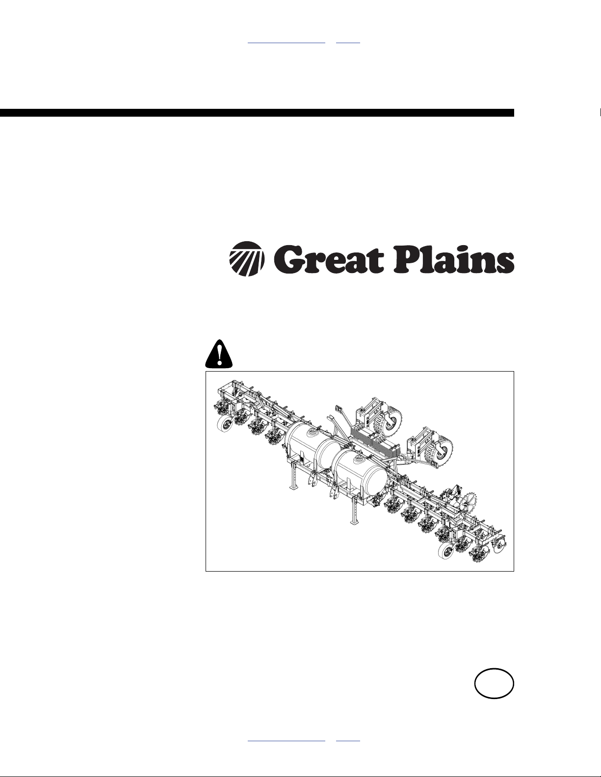
Table of Contents Index
Nutri-Pro® 40-Foot Fertilizer Applicator
Operator Manual
Model NP4000
Manufacturing, Inc.
www.greatplainsmfg.com
Read the operation manual entirely. When you see this symbol, the
subsequent instructions and warnings are serious - follow without
exception. Your life and the lives of others depend on it!
32344
Illustrations may show optional equipment not supplied with standard unit, or may show
NP30, NP3000 or NP40 models where the topic function is identical.
ORIGINAL INSTRUCTIONS
© Copyright 2012 Printed 2012-03-28 407-776M
Table of Contents Index
EN
Page 2

Table of Contents Index
Table of Contents Index
Page 3

Great Plains Manufacturing, Inc. Cover Index iii
Table of Contents
Important Safety Information ...................................... 1
Safety Decals ................................................................. 7
Introduction ................................................................12
Using This Manual........................................................12
Description of Unit ........................................................12
Models Covered .......................................................12
Intended Usage ........................................................12
Document Family......................................................12
Owner Assistance ........................................................13
Application Overview.................................................14
Implement System Components .................................. 14
Ground Drive System Components (Options)..........17
Hydraulic Drive System Components (Options) .......18
Trailing Nurse Tank Components.................................19
Nutri-Pro® Rear Hitch (Option).....................................19
Hitch (Option) and Nurse Tank Components (User-Pro-
visioned) ...........................................................20
Preparation and Setup ...............................................21
Initial Setup...................................................................21
Post-Delivery/Seasonal Setup......................................21
Pre-Application Setup...................................................21
Hitching Tractor to Applicator .......................................22
2-Point Hitching ........................................................22
Electrical Hookup......................................................23
Hydraulic Hose Hookup............................................ 24
Hydraulic Pump Hookup.......................................25
Raise Parking Stands...............................................25
Leveling Implement ...................................................... 26
Set Application Depth...............................................26
Front-to-Back Level (Spacers)..................................26
Variable Rate Setup (Option) ....................................... 27
Operating Instructions...............................................30
Pre-Start Checklist .......................................................30
Implement Locks .......................................................... 31
Lift-Assist Lock Channels .........................................31
Outer Wing Lock Channels.......................................31
Wing Lock Pins......................................................... 31
Inner Wing Lock Channels .......................................32
Inner Locks in Transport.......................................32
Inner Locks During Unfold ....................................32
Inner Wing Locks After Unfold..............................32
Inner Wing Locks in Field .....................................33
Inner Wing Locks Pre-Fold ...................................33
Outer Wing Fold Latches.......................................... 34
Raising/Lowering Applicator.........................................35
Raise For Transport (Folded)............................... 35
Raise Pre-Folding (Unfolded)............................... 35
Lower While Folded ............................................. 36
Lower While Unfolded .......................................... 36
Field Lower........................................................... 36
Unfolding and Folding .................................................. 37
Unfolding (At Field) .............................................. 37
Unfolding (Parking, Storage, Service).................. 38
Folding ................................................................ 39
Transport...................................................................... 40
Typical NP4000 Weights by Configuration........... 40
Transport Steps........................................................ 41
Final Implement Setup ................................................. 41
Loading Materials......................................................... 42
Filling Tanks ............................................................. 42
Tank Quick-Fill .....................................................42
Tank Lid Fill.......................................................... 43
Hitching Nurse Tank .................................................... 44
Mechanical Cart Hitching ......................................... 44
Making Nurse Tank Connections................................. 44
Fertilizer Operation ...................................................... 45
Ground Drive Operation ........................................... 45
Hydraulic Drive Operation ........................................ 45
Boom Operation ....................................................... 45
Start-Up Preparation (Either Pump) ......................... 45
Ground Drive Pump Start-Up ................................... 46
Prime the Ground Drive System. ......................... 46
Hydraulic Drive Start-Up .......................................... 46
Field Operations (Either Pump)................................ 46
Pauses and Turns .................................................... 46
Ground Drive Pauses and Turns.......................... 46
Hydraulic Drive Pauses and Turns....................... 46
Monitor Operation (Option) .......................................... 47
Starting Application with Console............................. 47
Ending Application ....................................................... 48
Field Set-Up Checklists................................................ 49
Field Operation Checklists ........................................... 50
First Pass ................................................................. 50
Pass Turns ............................................................... 50
Ending Application ................................................... 50
Short-Term Parking...................................................... 51
Long-Term Storage...................................................... 51
Adjustments ............................................................... 52
Application Height Adjustment ..................................... 53
Coulter Force ............................................................... 53
© Copyright 2010, 2011, 2012 All rights Reserved
Great Plains Manufacturing, Inc. provides this publication “as is” without warranty of any kind, either expressed or implied. While every precaution has been
taken in the preparation of this manual, Great Plains Manufacturing, Inc. assumes no responsibility for errors or omissions. Neither is any liability assumed for
damages resulting from the use of the information contained herein. Great Plains Manufacturing, Inc. reserves the right to revise and improve its products as
it sees fit. This publication describes the state of this product at the time of its publication, and may not reflect the product in the future.
2012-03-28 Cover Index 407-776M
Trademarks of Great Plains Manufacturing, Inc. include: Singulator Plus, Swath Command, Terra-Tine.
Registered Trademarks of Great Plains Manufacturing, Inc. include:
Air-Pro, Clear-Shot, Discovator, Great Plains, Land Pride, MeterCone, Nutri-Pro, Seed-Lok, Solid Stand,
Terra-Guard, Turbo-Chisel, Turbo-Chopper, Turbo Max, Turbo-Till, Ultra-Till, Ver ti-Till, Whirlfilter, Yield-Pro.
Brand and Product Names that appear and are owned by others are trademarks of their respective owners.
Page 4

iv NP4000 Table of Contents Index Great Plains Manufacturing, Inc.
Coulter Height and Castering................................... 54
Tool Bar Height Adjustment ......................................... 55
Weight Transfer Adjustment ........................................ 56
Weight Transfer Safety Information ......................... 56
2012+ Weight Transfer System ............................... 56
2011 Weight Transfer System ................................. 58
Weight Transfer Setup - 2011.................................. 59
Caster Angle Adjustment ............................................. 60
Changing Spacing.................................................... 60
2012+ Caster Adjustment ........................................ 61
90 Inch (30 inch In Row) Spacing ............................ 61
120 Inch (30 inch Out of Row) Spacing ................... 61
148 Inch (36/38 inch In Row) Spacing ..................... 61
2011 Caster Adjustment .......................................... 62
90 Inch (In Row) Spacing......................................... 62
120 Inch (Out of Row) Spacing................................ 62
Changing Spacing.................................................... 62
Row Implement Adjustments ....................................... 63
Terra-Tine™ Adjustments........................................ 63
Terra-Tine™ Down Force .................................... 63
Fertilizer Rate ............................................................. 64
Rate Setting Steps: ...................................................... 64
Determining Application Rate ...................................... 64
Ground Drive:....................................................... 64
Ground Drive Rate: NP4000-1236............................... 65
NP4000-1236 Fertilizer Rate ................................... 65
NP4000-1236 JohnBlue Reference Data................. 65
Ground Drive Rate: NP4000-1238............................... 66
NP4000-1238 Fertilizer Rate ................................... 66
NP4000-1238 JohnBlue Reference Data................. 66
Ground Drive Rate: NP4000-1630 Standard ............... 67
NP4000-1630 Fertilizer Rate ................................... 67
NP4000-1630 JohnBlue Reference Data................. 67
Ground Drive Rate: NP4000-1630 Side Dress (SD).... 68
NP4000-1630(SD) (17-Row) Fertilizer Rate ............ 68
NP4000-1630(SD) JohnBlue Reference Data ......... 68
Select and Install Orifice Plates ................................... 69
Determine Orifice Size ......................................... 69
Install Orifice Plates ................................................. 70
Alternate Orifice Plates ........................................ 70
Row Shutoff ............................................................. 70
Strainer Adjustment ..................................................... 71
Ground Drive: Setting Relief Valve .............................. 71
Ground Drive: Set Pump Drive Range......................... 72
Ground Drive: Set Pump Rate Dial .............................. 72
Hydraulic Drive: Pump Pressure.................................. 73
Flow-Based Adjustment ........................................... 73
Dead-Head Adjustment............................................ 73
Troubleshooting......................................................... 74
General Implement Troubleshooting............................ 74
General Application Troubleshooting........................... 75
Ground Drive Pump Troubleshooting .......................... 76
Hydraulic Drive Pump Troubleshooting ....................... 77
Maintenance and Lubrication....................................78
Material Clean-Out .......................................................79
Tank Clean-Out ........................................................79
Liquid Fertilizer Strainer Maintenance ..........................80
Pump Maintenance and Repair ....................................81
Ace Hydraulic Pump .................................................81
Coulter Disc Replacement ........................................81
Hydraulic Maintenance .................................................82
Bleeding Lift Hydraulics ............................................82
Bleeding Fold Hydraulics ..........................................83
Wing Leveling ...............................................................84
Rear Eyebolt Adjustment..............................................84
Caster Brake Adjustment..............................................85
Pressure Plate Adjustment ...................................85
Chain Maintenance (Option).........................................86
Chain Slack...............................................................86
Lubrication and Scheduled Maintenance .....................87
Options ........................................................................92
Appendix A - Reference Information ......................101
Specifications and Capacities.....................................101
Tire Inflation Chart ......................................................104
Torque Values Chart ..................................................105
Chain Routing (Option)...............................................106
Hydraulic Diagrams ....................................................107
Orifice Plate Selection, Metric.................................109
Appendix B - Option Setup......................................110
Hydraulic Pump Setup................................................110
Pump Fittings and Needle Valve ............................110
Console Installation ................................................111
Appendix C - Accessory Installation ......................112
Side Dress Installation................................................112
Installing / Changing to Side Dress.........................112
Prepare Implement .............................................112
Install Wing Extension ........................................113
Dismount Rear Coulters .........................................113
Dismount One Coulter Connection .....................114
Install Side Dress Coulter .......................................115
Install Applicator Attachment ..............................115
Connect Coulter Tubing..........................................116
Shift 2-Point Hitch ...................................................117
Caster and Gauge Wheel Considerations ..........117
Reset and Disable Pumps ......................................117
Reverting Side Dress to Pre-Emergence................118
Prepare Implement .............................................118
Shift 2-Point Hitch ...................................................118
Disconnect Side Dress Coulter...............................119
Dismount Side Dress Coulter .............................120
Remount Rear Coulters ..........................................120
Connect Rear Coulters ...........................................121
Wing Extension.......................................................121
Enable and Reset Pumps .......................................121
Weight Kit Installation .................................................122
Tools Required: ......................................................122
Warranty ....................................................................123
Index ..........................................................................125
407-776M Table of Contents Index 2012-03-28
Page 5
Great Plains Manufacturing, Inc. Table of Contents Index 1
Important Safety Information
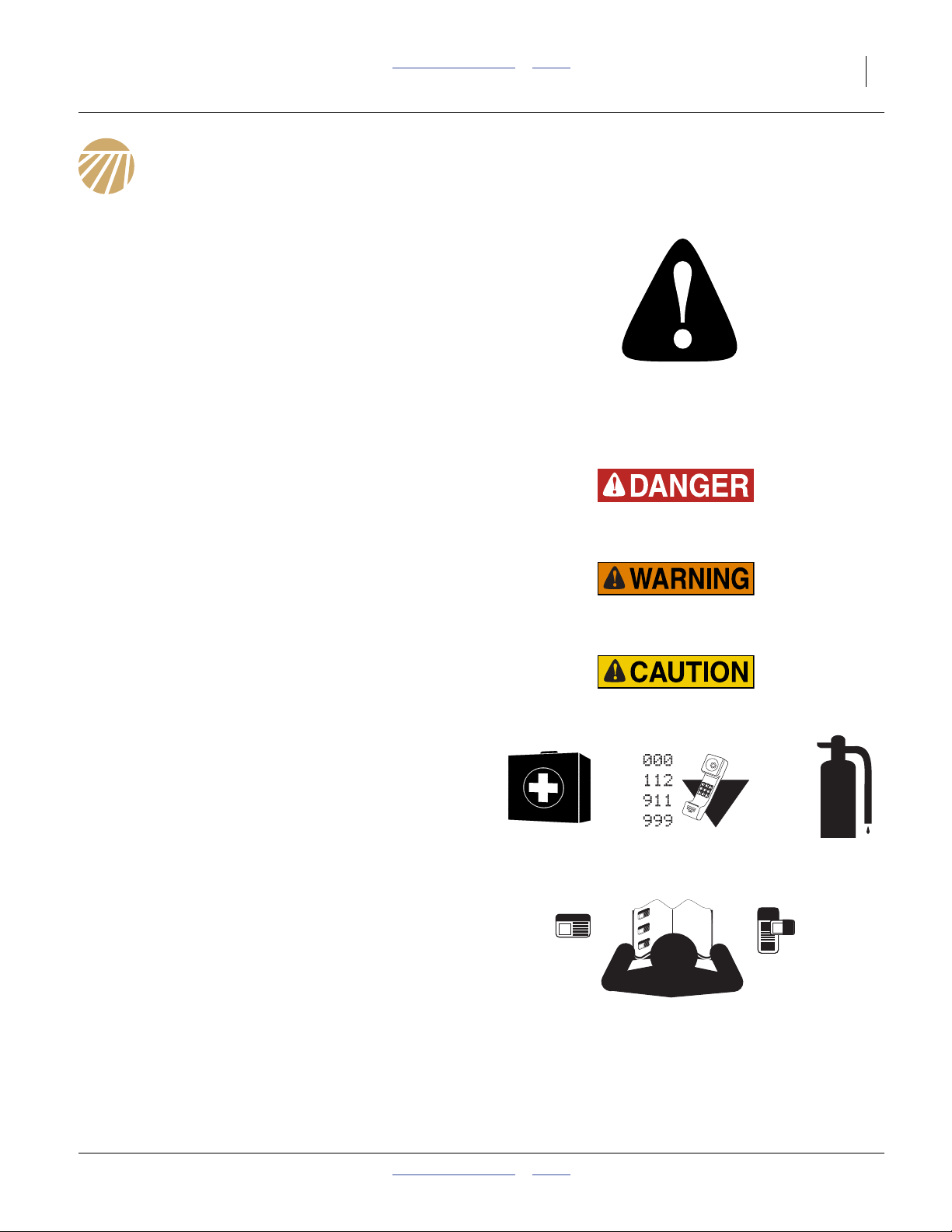
Look for Safety Symbol
The SAFETY ALERT SYMBOL indicates there is a
potential hazard to personal safety involved and extra
safety precaution must be taken. When you see this
symbol, be alert and carefully read the message that
follows it. In addition to design and configuration of
equipment, hazard control and accident prevention are
dependent upon the awareness, concern, prudence and
proper training of personnel involved in the operation,
transport, maintenance and storage of equipment.
Be Aware of Signal Words
Signal words designate a degree or level of hazard
seriousness.
DANGER, and the color Safety Red, indicate an
imminent hazard which, if not avoided, will result in death
or serious injury. This signal word is limited to the most
extreme situations, typically for machine components
that, for functional purposes, cannot be guarded.
WARNING, and the color Safety Orange, indicate a
potential hazard which, if not avoided, could result in
death or serious injury, and includes hazards that are
exposed when guards are removed. It may also be used
to alert against unsafe practices.
CAUTION, and the color Safety Yellow, indicate a
potential hazard which, if not avoided, may result in
minor or moderate injury. It may also be used to alert
against unsafe practices.
Prepare for Emergencies
▲ Be prepared if a fire starts
▲ Keep a first aid kit and fire extinguisher handy.
▲ Keep emergency numbers for doctor, ambulance, hospital
and fire department near phone. Know the reporting
requirement for spills or releases of the chemicals you are
using. Have contact numbers available.h
Be Familiar with Safety Decals
▲ Read and understand “Safety Decals” on page 7,
thoroughly.
▲ Read all instructions noted on the decals.
▲ Keep decals clean. Replace damaged, faded and illegible
decals.
2012-03-28 Table of Contents Index 407-776M
Page 6

2 NP4000 Table of Contents Index Great Plains Manufacturing, Inc.
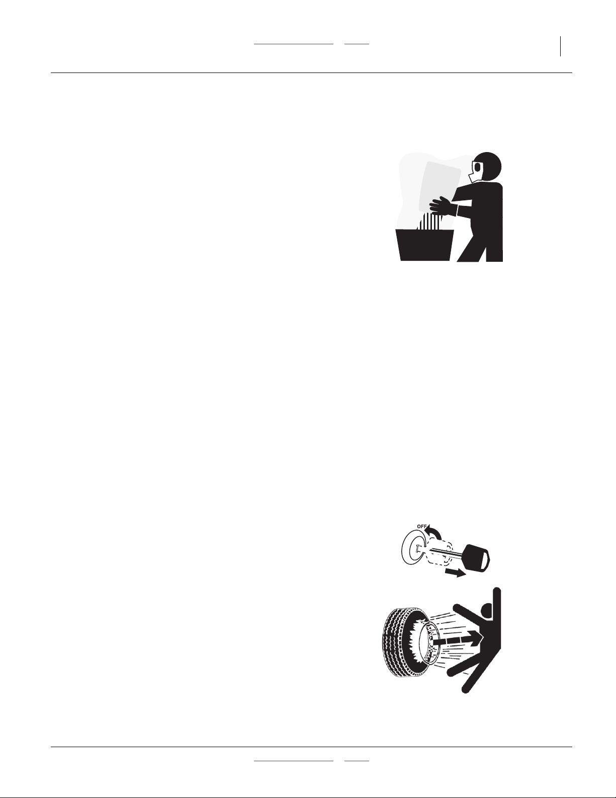
Wear Protective Equipment (PPE)
▲ Wear clothing and equipment appropriate for the job. Avoid
loose-fitting clothing.
▲ Waterproof, wide-brimmed hat
▲ Face shield, goggles or full face respirator.
▲ Prolonged exposure to loud noise can cause hearing
impairment or loss. Wear suitable hearing protection such
as earmuffs or earplugs.
▲ Avoid wearing entertainment headphones while operating
machinery. Operating equipment safely requires the full
attention of the operator.
▲ Goggles with side shields or a full face respirator is
required if handling or applying dusts, wettable powders, or
granules or if being exposed to spray mist.
▲ Cartridge-type respirator approved for pesticide vapors
unless label specifies another type of respirator.
▲ Waterproof, unlined gloves. Neoprene is recommended.
▲ Cloth coveralls/outer clothing changed daily; waterproof
items if there is a chance of becoming wet with spray
▲ Waterproof apron
▲ Waterproof boots or foot coverings
▲ Do not wear contaminated clothing. Wash protective
clothing and equipment with soap and water after each use.
Personal clothing must be laundered separately from
household articles.
▲ Clothing contaminated with certain pesticides must be
destroyed according to state and local regulations. Read
chemical label for specific instructions.
Avoid High Pressure Fluids
Escaping fluid under pressure can penetrate the skin,
causing serious injury. This fertilizer applicator requires a
Power-Beyond port, which is always under pressure
when the tractor is running.
▲ Avoid the hazard by relieving pressure before disconnecting
hydraulic lines.
▲ Use a piece of paper or cardboard, NOT BODY PARTS, to
check for suspected leaks.
▲ Wear protective gloves and safety glasses or goggles when
working with hydraulic systems.
▲ If an accident occurs, seek immediate medical attention
from a physician familiar with this type of injury.
407-776M Table of Contents Index 2012-03-28
Page 7
Great Plains Manufacturing, Inc. Table of Contents Index Important Safety Information 3
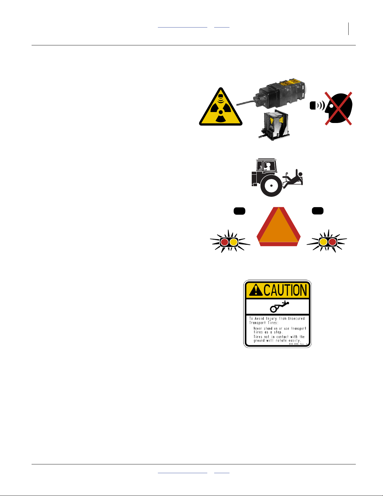
Minimize Radiation Exposure
The DICKEY-john® RVS II and RVS III Radars are
intentional radiators of RF energy. Although its radiated
energy level is far below the limits set by
EN 61010-1:1993 A2:1995-Chapter 12.4, it is advisable
not to look directly into the face of the unit.
The radar must radiate toward the ground and at least
20 cm (8 inches) away from a human during use to
comply with the RF human exposure limits as called out
in FCC 47 CFR Sec.2.1091. DO NOT RE-MOUNT OR
USE THE RADAR IN A MANNER INCONSISTENT
WITH ITS DEFINED USE.
Keep Riders Off Machinery
Riders obstruct the operator’s view. Riders could be
struck by foreign objects or thrown from the machine.
▲ Never allow children to operate equipment.
▲ Keep all bystanders away from machine during operation.
Use Safety Lights and Devices
Slow-moving tractors and towed implements can create
a hazard when driven on public roads. They are difficult
to see, especially at night.
▲ Use flashing warning lights and turn signals whenever
driving on public roads.
▲ Use lights and devices provided with implement.
Tires Not a Step
Do not use gauge wheel or lift-assist tires as steps. A tire
could spin underfoot, resulting in a fall onto the
implement or ground, possibly causing serious injury.
▲ The gauge wheel tires can be in poor ground contact at any
time, even with the fertilizer applicator lowered in the field.
They can appear to be in ground contact, and spin easily, in
multiple conditions.
▲ The lift-assist tires can be in poor ground contact, or out of
ground contact, whenever the fertilizer applicator is
lowered.
2012-03-28 Table of Contents Index 407-776M
Page 8
4 NP4000 Table of Contents Index Great Plains Manufacturing, Inc.
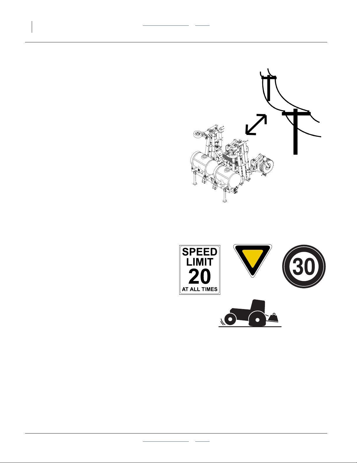
Remain Clear of Overhead Lines
▲ If the fertilizer applicator contacts a power line, lethal
voltage may be present on all metal parts. At higher voltage,
the applicator does not need to be in line contact for the
hazard to exist. Maintain at least 10 foot (3 m) clearance.
▲ Electrocution can occur without direct contact between the
energized fertilizer applicator and a person near the
fertilizer applicator.
▲ Watch for sagging, damaged or low electrical lines. The
folded fertilizer applicator could contact lines lower than
13 ft. (4 m). Overhead lines at farm structures are a
particular hazard. An incorrectly folded implement is at risk
from lines lower than 22 ft. (7 m).
▲ Watch for all electrical lines during folding and unfolding
operations. Use a spotter during folding and unfolding.
Know the location and height of all lines during transport
and in fields.
▲ If an electrical hazard is observed while on the ground near
the applicator, hop at least 30m (100 feet) away with both
feet together and summon professional help. At higher
voltage, lethal voltage gradients can also be present at the
soil surface.
▲ Consult your tractor manual for advice on how to respond
to an electrical hazard event while in the cab.
Transport Machinery Safely
Maximum transport speed for implement is 20 mph (32
kph), 13 mph (22 kph) in turns. Some rough terrains
require a slower speed. Sudden braking can cause a
towed load to swerve and upset.
▲ Tow nurse tank separately. Do not tow a nurse tank in train
with the implement on public roads.
▲ 3-point implements reduce weight on steering tires. Verify
that tractor is correctly ballasted. Watch for signs of poor
steering traction.
▲ Carry reflectors or flags to mark fertilizer applicator in
case of breakdown on the road.
▲ Verify that the implement is properly folded (page 39).
▲ Keep clear of overhead power lines and other obstructions
when transporting. Refer to transport dimensions under
“Specifications and Capacities” on page 101.
▲ Do not exceed 20 mph. Never travel at a speed which does
not allow adequate control of steering and stopping. Reduce
speed if towed load is not equipped with brakes.
▲ Reduce speed on rough roads.
▲ Comply with national, regional and local laws.
▲ Do not fold or unfold the fertilizer applicator while the
tractor is moving.
407-776M Table of Contents Index 2012-03-28
Page 9
Great Plains Manufacturing, Inc. Table of Contents Index Important Safety Information 5
Handle Chemicals Properly
Agricultural chemicals can be dangerous. Improper use
can seriously injure persons, animals, plants, soil and
property.
▲ Read and follow chemical supplier instructions.
▲ Wear protective clothing.
▲ Handle all chemicals with care.
▲ Agricultural chemicals can be dangerous. Improper use can
seriously injure persons, animals, plants, soil and property.
▲ Inhaling smoke from any type of chemical fire is a serious
health hazard.
▲ Store or dispose of unused chemicals as specified by the
chemical manufacturer.
▲ If chemical is swallowed, carefully follow the chemical
manufacturer’s recommendations and consult with a doctor.
▲ If persons are exposed to a chemical in a way that could
affect their health, consult a doctor immediately with the
chemical label or container in hand. Any delay could cause
serious illness or death.
▲ Dispose of empty chemical containers properly. By law
rinsing of the used chemical container must be repeated
three times. Puncture the container to prevent future use. An
alternative is to jet-rinse or pressure rinse the container.
▲ Wash hands and face before eating after working with
chemicals. Shower as soon as application is completed for
the day.
▲ Apply only with acceptable wind conditions. Wind speed
must be below 5 mph. Make sure wind drift of chemicals
will not affect any surrounding land, people or animals.
▲ Never wash out a hopper within 100 feet of any freshwater
source or in a car wash.
Shutdown and Storage
▲ Park on level ground.
▲ Unhitch and store the fertilizer applicator in an area where
children normally do not play.
Tire Safety
Tire changing can be dangerous and should be
performed by trained personnel using correct tools and
equipment.
▲ When inflating tires, use a clip-on chuck and extension hose
long enough for you to stand to one side–not in front of or
over tire assembly. Use a safety cage if available.
▲ When removing and installing wheels, use wheel-handling
equipment adequate for weight involved.
2012-03-28 Table of Contents Index 407-776M
Page 10

6 NP4000 Table of Contents Index Great Plains Manufacturing, Inc.
Practice Safe Maintenance
▲ Understand procedure before doing work. Use proper
tools and equipment. Refer to this manual.
▲ Work in a clean, dry area.
▲ Lower the fertilizer applicator, put tractor in park, turn off
engine, and remove key before performing maintenance. If
work must be performed with implement raised, use blocks
or jackstands rated for the fertilizer applicator weight.
▲ Make sure all moving parts have stopped and all system
pressure is relieved.
▲ Allow applicator to cool completely.
▲ Disconnect battery ground cable (-) before servicing or
adjusting electrical systems.
▲ Welding: Disconnect battery ground. Avoid fumes from
heated paint.
▲ Inspect all parts. Make sure parts are in good condition
and installed properly.
▲ Remove buildup of grease, oil or debris.
▲ Remove all tools and unused parts from fertilizer
applicator before operation.
Safety At All Times
Thoroughly read and understand the instructions in this
manual before operation. Read all instructions noted on
the safety decals.
▲ Be familiar with all applicator functions.
▲ Operate machinery from the driver’s seat only.
▲ Do not leave applicator unattended with tractor engine
running.
▲ Do not stand between the moving tractor and applicator
during hitching.
▲ Keep hands, feet and clothing away from power-driven
parts.
▲ Wear snug-fitting clothing to avoid entanglement with
moving parts.
▲ Make sure all persons are clear of working area.
407-776M Table of Contents Index 2012-03-28
Page 11
Great Plains Manufacturing, Inc. Table of Contents Index Important Safety Information 7
Safety Decals
Safety Reflectors and Decals
Your implement comes equipped with all lights, safety
reflectors and decals in place. They were designed to
help you safely operate your implement.
▲ Read and follow decal directions.
▲ Keep lights in operating condition.
▲ Keep all safety decals clean and legible.
▲ Replace all damaged or missing decals. Order new decals
from your Great Plains dealer. Refer to this section for
proper decal placement.
▲ When ordering new parts or components, also request
corresponding safety decals.
To install new decals:
1. Clean the area on which the decal is to be placed.
2. Peel backing from decal. Press firmly on surface,
being careful not to cause air bubbles under decal.
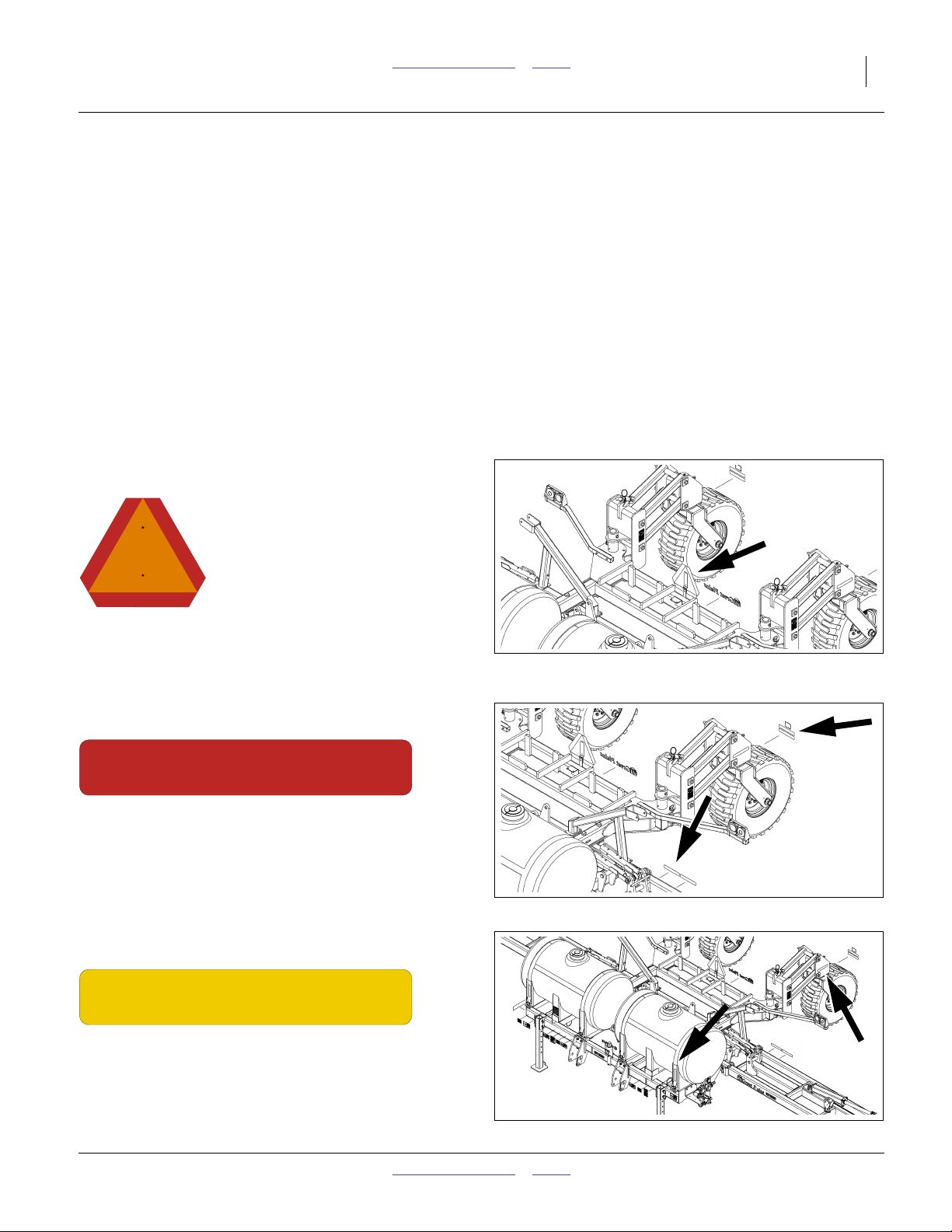
Reflector: Slow Moving Vehicle (SMV)
818-055C
On a post at rear of lift assist pivot weldment;
1 total
See “Transport” on page 40.
Reflectors: Red
838-266C
On rear face of caster weldments, above daytime
reflectors, and on rear face of inner wing weldments near
pivot and inside daytime reflectors;
4 total
See “Transport” on page 40.
32339
32339
Reflectors: Amber
838-265C
On outside faces of caster weldments, and on front faces
of outside tank cradles (on tankless models, the forward
reflectors are on the side faces of the front subframe);
4 total
See “Transport” on page 40.
2012-03-28 Table of Contents Index 407-776M
32339
Page 12
8 NP4000 Table of Contents Index Great Plains Manufacturing, Inc.
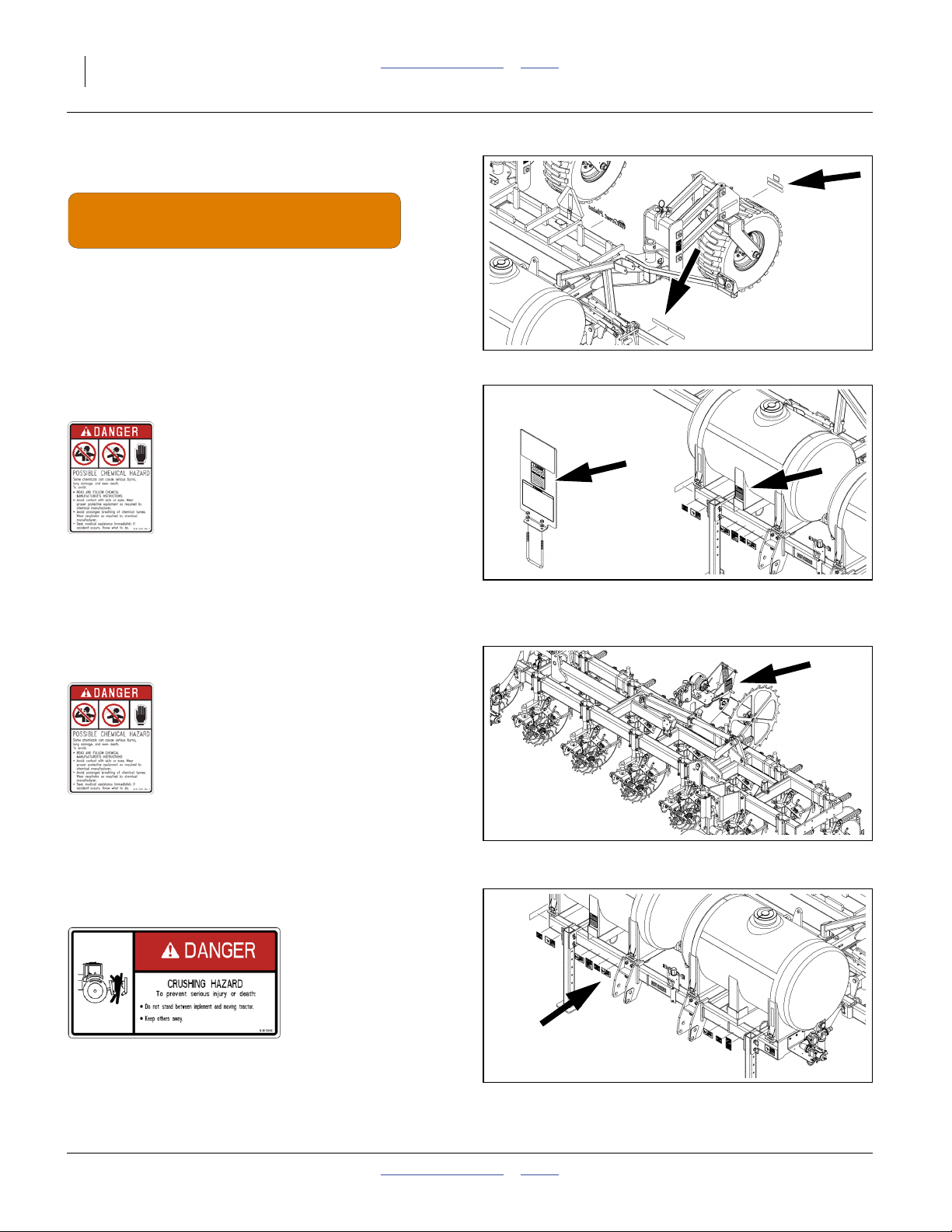
Reflectors: Daytime
838-267C
On rear face of caster weldments, below red reflectors,
and on rear face of inner wing weldments near pivot and
outside red reflectors;
4 total
See “Transport” on page 40.
32339
Danger: Possible Chemical Hazard (Option)
818-323C
On decal mount at optional rear hitch and/or on front face
of each center tank leg;
1 total
See “Loading Materials” on page 42.
Danger: Possible Chemical Hazard (Option)
818-323C
On left face of ground drive pump mount;
1 total
See “Loading Materials” on page 42.
Danger: Hitch Crush
818-590C
32339 32339
32344
On front face of 3-point hitch arms;
2 total
32339
See “Hitching Tractor to Applicator” on page 22.
407-776M Table of Contents Index 2012-03-28
Page 13

Great Plains Manufacturing, Inc. Table of Contents Index Important Safety Information 9
Danger: Electrocution
838-599C
On front face of inner wing, near inner pivot;
2 total
See “Remain Clear of Overhead Lines” on page 4.
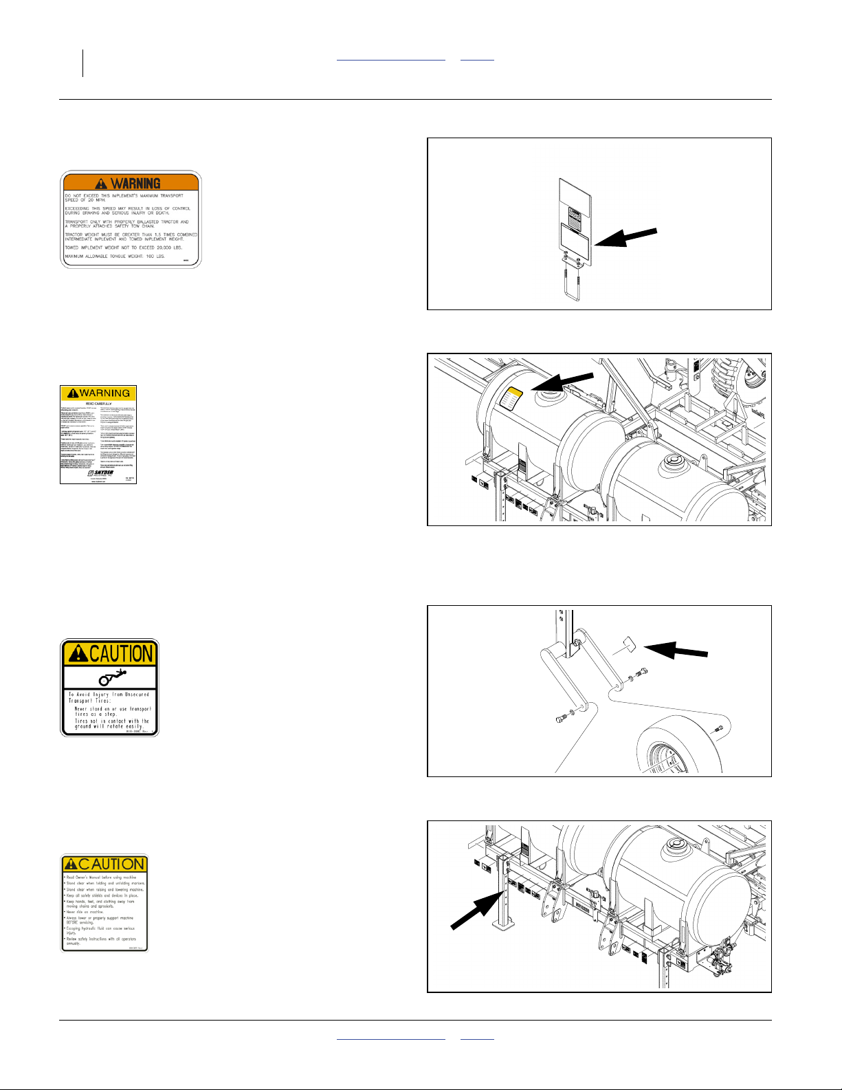
Warning: Speed
818-337C
On front of front cross tube right of hitch;
1 total
See “Transport” on page 40.
Warning: High Pressure Fluid
818-437C
32339
32339
On front face front frame at right end, and on left and
right faces of parallel arm mounts;
5 total
32339
See “Hitching Tractor to Applicator” on page 22.
Warning: Moving Parts (Option)
818-860C
31946
On left face ground drive pump mount;
1 total
2012-03-28 Table of Contents Index 407-776M
Page 14
10 NP4000 Table of Contents Index Great Plains Manufacturing, Inc.
Warning: Towing (Option)
848-551C
On decal mount at optional rear hitch;
1 total
32339
See “Hitching Nurse Tank” on page 44.
Warning: Tank Safety (Option)
Snyder 977176
On upper front face of each tank:
0 or 2 total
Replacement decals available from Snyder Industries:
www.snydernet.com
See “Loading Materials” on page 42.
Caution: Tires Not A Step
818-398C
On outside face of caster arms above tires;
2 total
See “Tires Not a Step” on page 3.
Caution: General
818-587C
32339
32318
On front of front frame tube right of hitch;
1 total
32339
See “Important Safety Information” on page 1.
407-776M Table of Contents Index 2012-03-28
Page 15
Great Plains Manufacturing, Inc. Table of Contents Index Important Safety Information 11
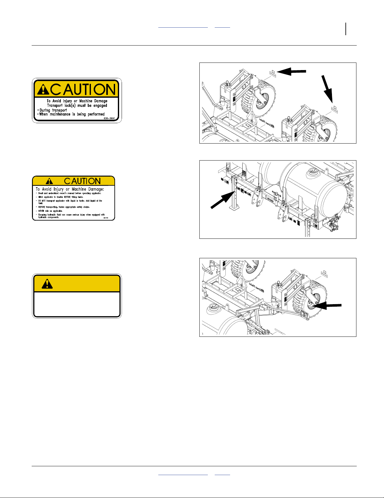
Caution: Transport Locks
838-380C
On rear face of caster weldments, above red reflectors;
2 total
See “Important Safety Information” on page 1.
Caution: Applicator
848-736C
On front of front frame tube right of hitch;
1 total
See “Loading Materials” on page 42.
32339
32339
Caution: Tire Pressure and Torque
848-801C
CAUTION
To Avoid Injur y or Machine Damage from Improper Tire
Inflation or Torquing of Wheel Bolts:
Maximum inflation pressure of tires is 80 psi.
Torque wheel bolts to 300 lb-ft.
On rim of each lift assist wheel;
2 total
See “Tire Safety” on page 5.
848 801C
32339
2012-03-28 Table of Contents Index 407-776M
Page 16

12 NP4000 Table of Contents Index Great Plains Manufacturing, Inc.
Introduction
Great Plains welcomes you to its growing family of new
product owners. Your Nutri-Pro® 40-Foot Fertilizer
Applicator has been designed with care and built by
skilled workers using quality materials. Proper setup,
maintenance, and safe operating practices will help you
get years of satisfactory use from the machine.
Description of Unit
The NP4000 is a fertilizer applicator implement. It has a
working width (swath) of 36, 38 or 40 feet (11, 11.6 or
12.2 m). The applicator has single or triple coulters for
sub-soil application of conventional liquid fertilizer from
optional on-board or user-provisioned tanks.The NP4000
has a lift-assisted 2-point hitch.
The NP4000 model is designed for use with an
optional ground-drive CDS-John Blue piston pump,
optional variable-rate Ace hydraulic drive pump,
or a user-provisioned pump. A Raven SCS 450 console
is available for the 3-section variable-rate manifold.
Models Covered
This manual applies to Great Plains applicator models:
NP4000-1236 12-row 36-inch spacing (91.4 cm)
NP4000-1238 12-row 38-inch spacing (96.5 cm)
NP4000-1630 16- and 17-row 30-inch (76.2 cm)
Figure 1
NP4000 Fertilizer Applicator
Using This Manual
This manual familiarizes you with safety, assembly,
operation, adjustments, troubleshooting, and
maintenance. Read this manual and follow the
recommendations to help ensure safe and efficient
operation.
The information in this manual is current at printing.
Some parts may change to assure top performance.
32344
Intended Usage
Use the NP4000 Fertilizer Applicator to apply compatible
liquid fertilizers. Do not modify Great Plains-provisioned
components, or install user-provisioned components,
except as authorized or recommended by Great Plains.
Document Family
407-776M NP4000a Operator/Rate Manual
(this document)
407-776P NP4000 Parts manual
407-776Q NP4000 Pre-Delivery manual
Manuals for Options:
016-0159-831 Raven SCS-450 Installation, Operation
and Service manual
12-M-43 CDS-John Blue NGP Pump Parts and
Instructional manual
HYD-MAN
b
Ace Pump Instruction manual
a. For NP30L and NP40L, see manual 407-313M.
For NP3000, see manual 407-613M.
b. Available from Ace Pump Corporation:
http://www.acepumps.com
Identifies an Economic (not a Safety) Risk:
NOTICE provides a crucial point of information related to the
current topic. Read and follow the instructions to avoid damage
to equipment and ensure desired field results.
Note: This form sets off useful information about the
current topic, or forestalls possible
misunderstanding.
Right-hand and left-hand as used in
this manual are determined by facing
the direction the machine will travel
while in use unless otherwise stated.
An orientation rose in some line art
illustrations shows the directions of:
Up, Back, Left, Down, Front, Right.
11 11 50
Two-digit callouts in the range to refer to the
same tank and Nutri-Pro® plumbing system
components throughout this manual. and above
refer to parts of Options (see Appendix C).
“Option” refers to components not part of the standard
product, and not “optional” steps. If the component is
installed, the instructions apply.
51
R
F
U
B
L
D
407-776M Table of Contents Index 2012-03-28
Page 17
Great Plains Manufacturing, Inc. Table of Contents Index Introduction 13
Owner Assistance
If you need customer service or repair parts, contact a
Great Plains dealer. They have trained personnel, repair
parts and equipment specially designed for Great Plains
products.
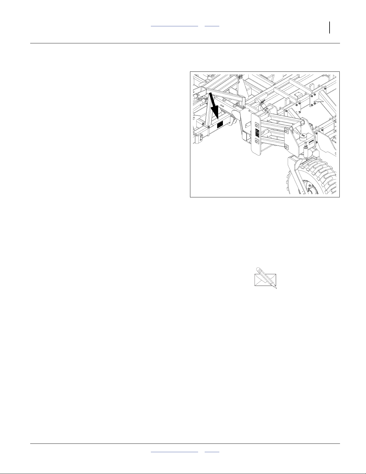
Refer to Figure 2
Your machine’s parts were specially designed and
should only be replaced with Great Plains parts. Always
use the serial and model number when ordering parts
from your Great Plains dealer. The serial-number plate is
located on the rear face of the center frame, ahead of the
left caster pivot.
Record your fertilizer applicator model and serial number
here for quick reference:
Model Number:__________________________
Serial Number: __________________________
Your Great Plains dealer wants you to be satisfied with
your new machine. If you do not understand any part of
this manual or are not satisfied with the service received,
please take the following actions.
1. Discuss the matter with your dealership service
manager. Make sure they are aware of any problems
so they can assist you.
2. If you are still unsatisfied, seek out the owner or
general manager of the dealership.
Figure 2
Serial Number Location
For further assistance write to:
Product Support
Great Plains Mfg. Inc., Service Department
PO Box 5060
Salina, KS 67402-5060
gp_web_cs@greatplainsmfg.com
785-823-3276
32348
2012-03-28 Table of Contents Index 407-776M
Page 18

14 NP4000 Table of Contents Index Great Plains Manufacturing, Inc.
Application Overview
Tank, plumbing and setup requirements differ for ground
drive and hydraulic drive applicators. The next few pages
provide an overview of both systems.
Implement System Components
This list presumes that the implement has system
components factory-installed by Great Plains. The list
includes all components for either the preset or hydraulic
drive pumping system.
If the implement has aftermarket components, part or all
of this information may not apply to your operations.
Consult the manual or other documentation for your tank
or pump.
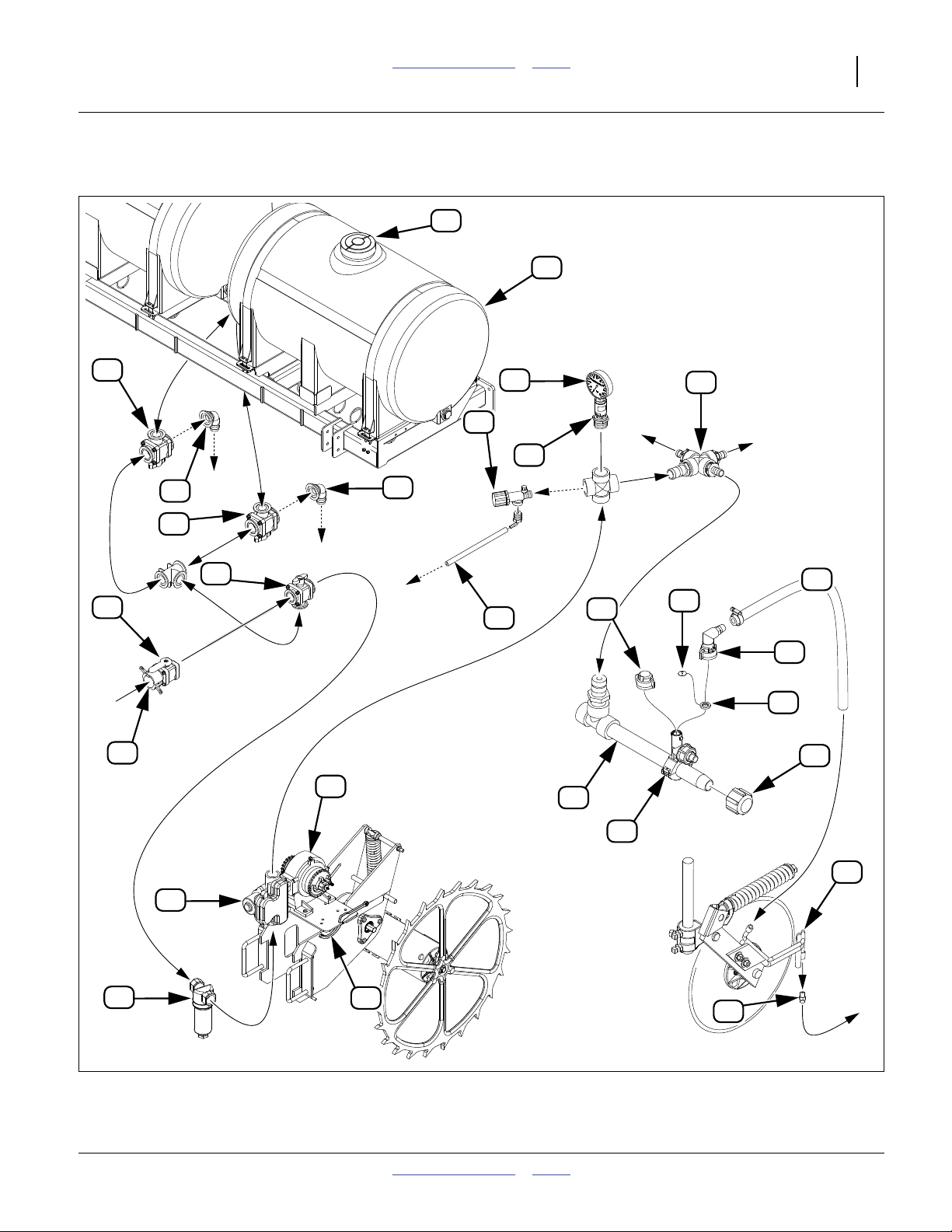
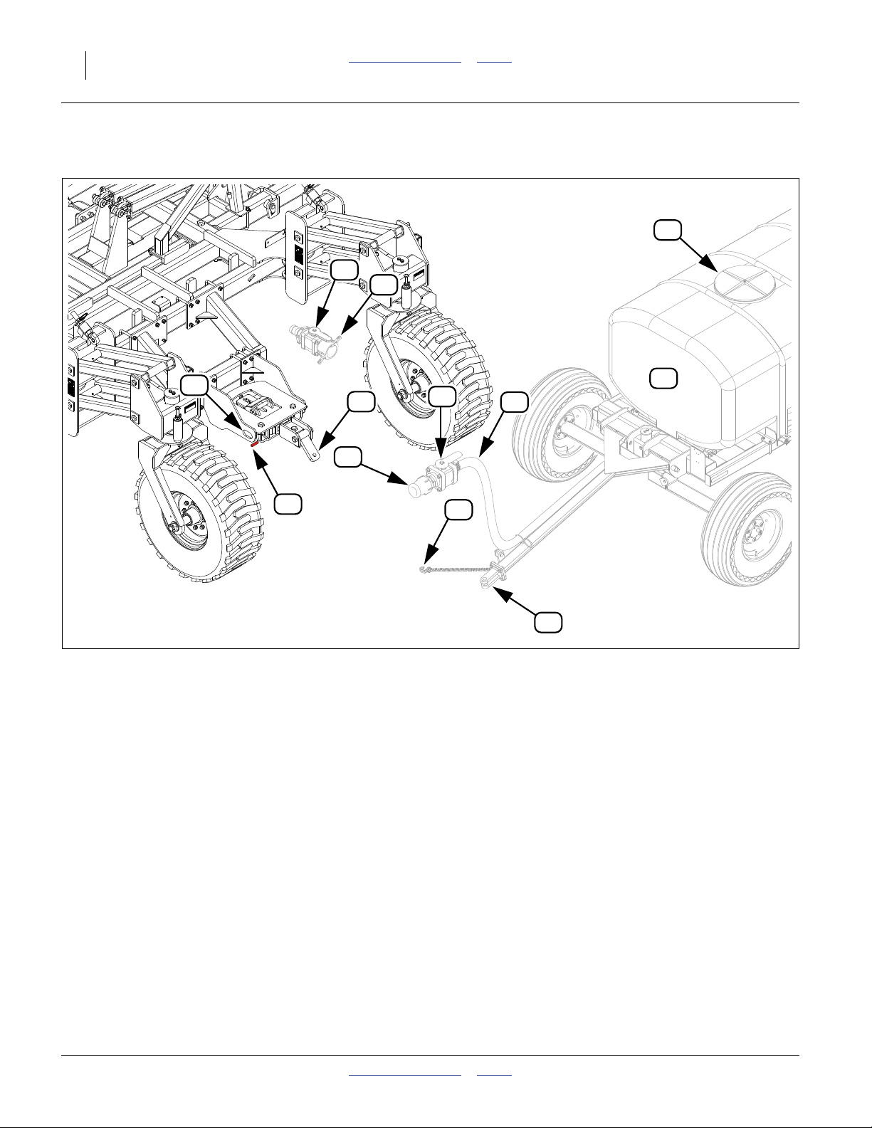
Refer to Figure 3 on page 17 and Figure 4 on page 18
11. Application Tank
Tank Option: The system depicted shows the
optional twin 300 gallon tanks, which includes the
quick-fill inlet assembly. A user-provisioned fertilizer
supply tank may be a trailing nurse tank cart, or may
be tractor-mounted.
A trailing nurse tank cart requires the optional nurse
tank hitch (page 98) on the implement. The cart
must be full-trailering, and not semi-mounted. The
Great Plains plumbing systems are not
pre-configured for user-provisioned tanks.
System Clogging Risk:
Use only pre-mixed liquid fertilizer. Regardless of the tank
type used, or its capabilities, do not use dry fertilizer
mixes with the Nutri-Pro® applicator.
12. Vented Tank Lid
Tank Option: A fully sealed tank must be vented
during operation. If the tank has a control for this, it
may be part of the top tank lid, or a separate
valve.Each on-board tank has a 10in vented
screw-on lid. Tanks may be filled at the top or via the
quick fill .
13. Tank Discharge Valves
Tank Option: Each on-board tank has its own valve,
which switches the tank discharge port between
these states:
tank connected to selector valve
tank discharge closed (shut off at valve)
tank connected to tank drain elbow
Discharge valves are normally open to the selector.
The may be closed individually to prevent
tank-to-tank transfer on slopes.
16
15
14
Note: Callouts 11 to 50, correspond to the items
beginning below, and identify the same
components throughout this manual.
14. Tank Drain Elbow
Tank Option: This open elbow fitting is used for
material recovery and tank wash-out (page 79).
15. Selector Valve
Tank Option: This valve is included with the optional
on-board tank system. The valve switches the tank
plumbing between three states:
tank plumbing connected to inlet
16
tank plumbing shut off at valve
tank plumbing connected to pump system ( , )
16. Supply Inlet
Tank Option: With the optional on-board tanks, or
without the tanks, but with the trailer hitch option, the
inlet of the NP4000 applicator is a 2 inch cam-lock
quick coupler receptacle (female, FCL). The tank
supply hose fitting must be, or be adapted to 2in
MCL.
17. Inlet Shut-Off Valve
Tank Option: This valve is open only during tank
filling with on-board tanks. This valve is
customer-provisioned for tractor-mounted or trailing
nurse tank configurations.
18. Strainer
Tank Option: This fitting contains an 80 mesh screen
for filtering large particles and coagulates in the
fertilizer, preventing blockage at the orifice plates .
See page 69 for alternative screen sizes and
page 80 for maintenance.
19. Ground Drive Pump
Ground Drive Option: The CDS-John Blue
NGP-7055-K has a capacity of 34 gallons/minute
(129 liters/minute). See the 12-M-43 CDS-John Blue
NGP Pump Parts and Instructional manual for
maintenance.
20. Pump Adjustment Dial
Ground Drive Option: This 0-to-10 adjustment sets
the percentage of rated gpm/lpm to use. Settings
below 2 are not recommended.
Pump and application rate are set by a combination
of ground drive sprockets (not shown) and dial
setting. See page 64 for ground drive rate setting.
19 27
38
407-776M Table of Contents Index 2012-03-28
Page 19

Great Plains Manufacturing, Inc. Table of Contents Index Application Overview 15
21. Pump Adjustment Tool
Ground Drive Option: Adjusting the setting dial may
require some mechanical assistance. A slot is
provided to store the tool at the pump when not
being used for adjustments.
22. Passive Manifold
Ground Drive Option:
The factory configuration of this fitting has two
outlets capped. The third is plumbed to the optional
front boom.
With user-provisioned fittings and hoses, this
manifold can split the flow across two booms, or
across three sections of a single boom.
However configured, equal flow is assured by the
orifice plates .
38
23. Gauge Protector
Ground Drive Option: This fitting transmits manifold
pressure to the pressure gauge , and protects the
24
gauge from direct contact with corrosive fertilizer.
24. Pressure Gauge
Ground Drive Option: This 0-to-100 psi gauge
reports the pressure in the manifold, which is
typically 15-40 psi during application. The pressure
should be above zero only when fertilizer is flowing.
The back-pressure at the nozzle orifices falls
38
quickly when the pump stops.
Check the pressure periodically during application.
If it rises to over 65 psi, the relief valve may be
activating. See also pressure sensor .
25
32
25. Relief Valve
Ground Drive Option: Adjust this valve to activate at
65 psi (page 71). This valve protects the manifold
against blockages, and from over-pressure due to
orifice sizes too small for the application rate or the
material viscosity.
26. Dump Line
Ground Drive Option: If the relief valve operates,
25
material is jettisoned at this tube. If you observe
dumping, check the pressure and review the orifice
38
plate configuration.
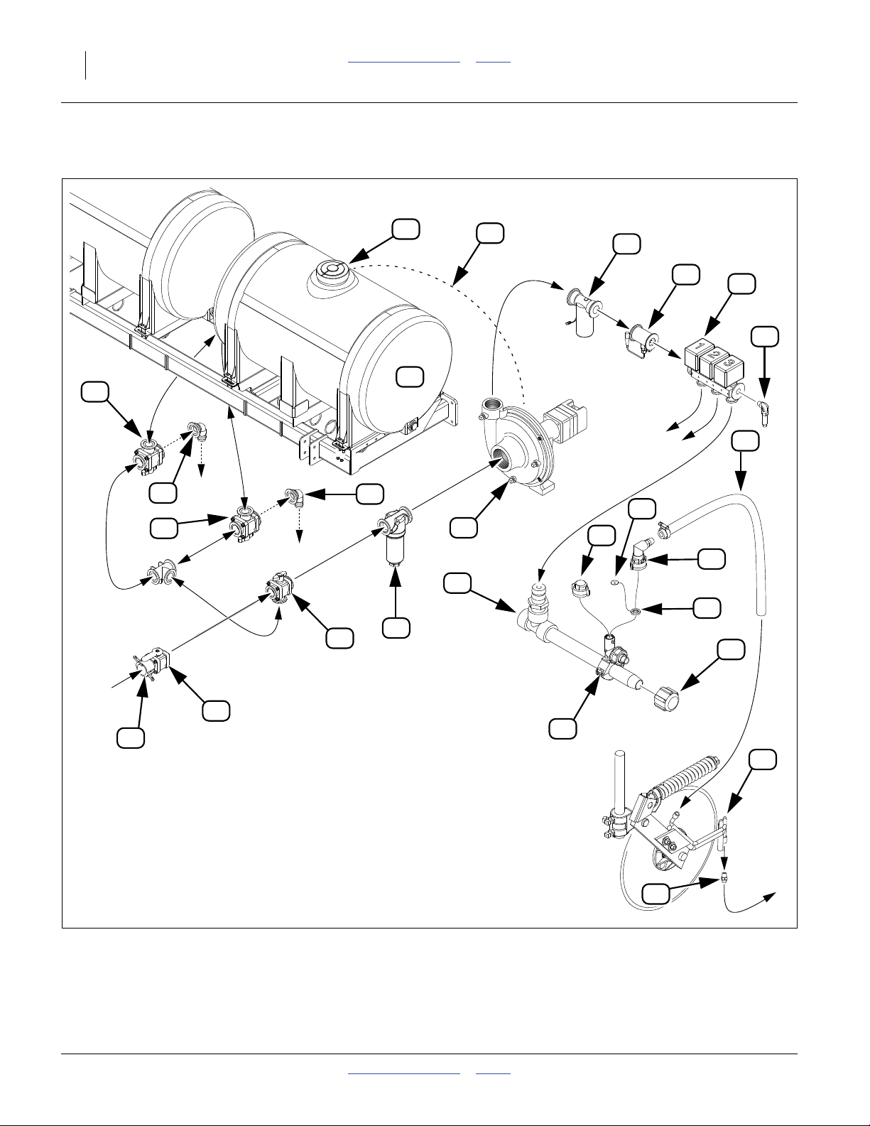
27. Hydraulic Drive Pump
Hydraulic Drive Option: The Ace
FMC-150F-HYD-206 has a capacity of up to
150 gallons/minute (560 liters/minute). See the
HYD-MAN Ace Pump Instruction manual for
maintenance.
28. Air Bleed Line
This line to the tank enabled pump priming by
bleeding off air. If using an off-implement tank, a
user-provisioned bleed line or bleed valve must be
provided for pump priming.
29. Flow Control Valve
Hydraulic Drive Option: Under the control of the
console (not shown) this valve is being constantly
adjusted to regulate pump output to the current
application rate (as reported by the flow meter ).
Only one flow control valve can be controlled by a
single Raven SCS450 console.
30. Flow Meter
Hydraulic Drive Option: This sensor reports the
actual material rate entering the hydraulic drive
manifold. As it detects variations from your desired
rate, it signals the console to adjust the control
29
valve . Only one flow meter can be monitored by a
single Raven SCS450 console.
31. Section Valves
Hydraulic Drive Option:
There are three On/Off solenoid valves (1, 2 & 3).
The factory configuration uses only valve 1. Valves 2
and 3 have their outlets capped.
The valves open and close under the control of
BOOM switches on the Raven SCS 450a or other
compatible console.
32. Pressure Sensor
Hydraulic Drive Option: The optional Raven
SCS 450 console displays the manifold pressure
during operation. This is measuring essentially the
same pressure as the mechanical pressure
gauge . Only one pressure sensor can be
24
monitored by a single Raven SCS450 console.
33. Boom
Boom Option: There is one boom assembly per
implement section. Booms may be different lengths,
and have different drop counts at center and on
wings.
The factory configuration provides the booms
interconnected as a single section.
34. End Cap
Boom Option: In the factory configuration, the wing
booms each have a cap. These caps are removed
for clean-out (see page 79).
30
a. Although the Raven SCS450 has six section valves, the harness provided has only four Valve leads. Controlling more than three
valves with a single SCS450 would require the purchase of an alternate harness from Raven.
2012-03-28 Table of Contents Index 407-776M
Page 20

16 NP4000 Table of Contents Index Great Plains Manufacturing, Inc.
35. Boom Clamp
Boom Option: This fitting taps the boom for delivery
to the row. it contains an 8 psi check valve, which
prevents dribbling when the system is idle. Seasonal
clean-out (page 79) is necessary to prevent
over-winter freezing of residual material.
Booms typically have more boom clamps than
applicator rows (the same boom assembly is used
on multiple implement models). Active rows have
nozzle bodies . Inactive stations have shutoff
36
caps .
39
36. Shutoff Cap
Boom Option: Unused boom clamp stations are
capped. Use a gasket (with or without plate) under a
cap.
37. Gasket
Boom Option: This flat O-ring seals the nozzle
39 36 35
body or shutoff cap to the boom clamp . The
inside diameter of the gasket is grooved to accept an
orifice plate . Do not operate without a gasket.
38
38. Orifice Plate
Boom Option: These stainless steel plates restrict
the flow to the row. Their function is to create
back-pressure to the pump, and ensure equal flow at
all rows.
The standard boom option includes complete sets of
plates at three sizes. Additional plate sizes are
available. The orifice size must be matched to the
rate and viscosity of the material being applied. See
page 70 for plate selection and installation.
39. Nozzle Body
Boom Option: This fitting adapts the boom clamp to
tubing, and may be positioned for forward or rear
tubing direction.
40. Drop Tubing
Boom Option: This tubing carries the material to the
row.
41. Applicator Arm and Tubing
Coulter Option: The tubing is protected behind arm
structure. The arm may be adjusted for release
depth relative to coulter depth (page 54).
42. Applicator Nozzle
Coulter Option: This stainless steel fitting (part
number 828-046C) delivers the material to the trench
opened by the coulters. It has an 0.040 in. orifice
port.
407-776M Table of Contents Index 2012-03-28
Page 21
Great Plains Manufacturing, Inc. Table of Contents Index Application Overview 17
Ground Drive System Components (Options)
See page 14 to page 16 for callout descriptions
12
11
13
17
16
14
13
15
20
14
25
26
24
23
33
36
22
40
38
39
37
34
35
41
19
18
21
42
Figure 3
Options: Ground Drive Plumbing with On-Board Tanks, Boom and Coulter Attachment
2012-03-28 Table of Contents Index 407-776M
31955
Page 22
18 NP4000 Table of Contents Index Great Plains Manufacturing, Inc.
Hydraulic Drive System Components (Options)
See page 14 to page 16 for callout descriptions.
13
14
13
15
14
12
18
11
27
33
28
36
29
38
30
31
32
40
39
37
34
17
16
35
41
42
Figure 4
Options: Hydraulic Drive Plumbing with On-Board Tanks, Boom and Coulter Attachment
407-776M Table of Contents Index 2012-03-28
32001
Page 23

Great Plains Manufacturing, Inc. Table of Contents Index Application Overview 19
Trailing Nurse Tank Components
Refer to Figure 5 on page 20
Application Tank (user provisioned)
Consult tank documents for details of tank operation.
This manual presumes only that the tank has a
compatible coupler and shut-off valve. This manual
also presumes that an implement-mounted pump is
in use.
12. Vented Tank Lid (user provisioned)
16. Supply Inlet (user provisioned)
Great Plains supplies an inlet coupler, valve and
hose only with the on-board tank Option. In all other
configurations, the inlet connection (which might be
to pump or directly to boom) is field-installed.
17. Inlet Shut-Off Valve (user provisioned)
Nutri-Pro®Rear Hitch (Option)
Refer to Figure 5 on page 20
Items 43 through 45 are part of the rear hitch Option
(page 98).
43. Tongue Release Handle
Frees rear hitch tongue for alignment with nurse
tank tongue. See “Hitching Nurse Tank” on
page 44.
44. Chain Anchor
Two anchor points are provided for nurse tank safety
chains.
45. Rear Hitch Tongue
Accepts a 1 inch (2.6 cm) hitch pin.
46. Cart Hitch
A nurse tank cart must have a clevis hitch with a
1 inch locking pin. The tongue must be able to
elevate to a hitch height of 48 inches (122 cm) above
ground with the high clearance rear hitch, and
1
38
⁄2inches (97.7 cm) with the drop hitch.
47. Safety Chain
A minimum of one safety chain is required. Each
chain must be rated for the total weight of a fully
loaded cart. The optional nurse cart hitch on the
implement has anchor points for two chains.
48. Tank Supply Hose Quick-Coupler
The supply inlet of the NP4000 applicator is a 2 inch
male cam-lock quick coupler (MCL). The tank supply
hose fitting must be, or be adapted to 2in FCL.
49. Tank Supply Hose Shut-off Valve
This Nutri-Pro® manual mentions only a single
shutoff valve for the tank supply hose. Your tank may
have additional shutoff and/or flow management
valves. Consult your tank manual.
50. Tank Supply Hose
The tank supply hose must be large enough to
support the application rates intended. A hose ID of
11⁄2inch or larger suffices.
45
2012-03-28 Table of Contents Index 407-776M
Page 24
20 NP4000 Table of Contents Index Great Plains Manufacturing, Inc.
Hitch (Option) and Nurse Tank Components (User-Provisioned)
See page 19 for callout descriptions
12
17
16
44
43
45
49
48
47
Figure 5
Trailing Nurse Tank Hitch
11
50
46
32349
407-776M Table of Contents Index 2012-03-28
Page 25

Great Plains Manufacturing, Inc. Table of Contents Index 21
Preparation and Setup
This section helps you prepare your tractor and NP4000
Fertilizer Applicator for use, and covers tasks that need
to be done seasonally, or when the tractor/fertilizer
applicator configuration changes.
Before using the applicator in the field, you must hitch it
to a suitable tractor, inspect systems, level the applicator,
and configure the tanking system. Before using the
fertilizer applicator for the first time, and periodically
thereafter, certain adjustments and calibrations may be
required.
Initial Setup
See manual 407-776Q for pre-delivery items (normally
completed by dealer), and first-time/infrequent setup
tasks, including:
• Adjust optional hydraulic pump needle valve
(page 110).
• Install optional hydraulic drive console in tractor
(page 111).
• Install other Options not factory- or dealer-installed.
Post-Delivery/Seasonal Setup
On initial delivery, use with a new tractor, and seasonally,
check and as necessary, complete these items before
continuing to the routine setup items:
• Bleed hydraulic system (page 82).
• De-grease exposed cylinder rods if so protected at last
storage.
Pre-Application Setup
Complete this checklist before routine setup:
❑ Read and understand “Important Safety
Information” on page 1.
❑ Check that all working parts are moving freely, bolts
are tight, and cotter pins are spread.
❑ Check that all grease fittings are in place and
lubricated. See “Lubrication and Scheduled
Maintenance” on page 87.
❑ Check that all safety decals and reflectors are
correctly located and legible. Replace if damaged.
See “Safety Decals” on page 7.
❑ Inflate tires to pressure recommended and tighten
wheel bolts as specified. See “Tire Inflation Chart”
on page 104.
2012-03-28 Table of Contents Index 407-776M
Page 26
22 NP4000 Table of Contents Index Great Plains Manufacturing, Inc.
Hitching Tractor to Applicator
This manual presume the following (recommended)
operations sequence:
1. Hitch tractor to applicator for transport: below
2. Transport applicator separately from a trailing nurse
tank: page 40
3. Hitch a trailing nurse tank to applicator at field:
page 44
To prevent soil compaction on rows, set tractor wheels
between rows, for example: 60 inches center-to-center.
For hillsides and steep slopes, set tractor wheels as wide
as possible for maximum stability.
2-Point Hitching
Crushing Hazard:
Do not stand or place any body part between applicator and
moving tractor. You may be severely injured or killed by being
crushed between the tractor and applicator. Stop tractor
engine and set parking brake before attaching cables and
hoses.
The NP4000 is engineered to be used with Category II or
Category III tractors.
Refer to Figure 6
This implement is factory set for Category III tractors.
Category II requires an optional hitch pin kit (see
page 93).
In addition, the following bushings (not supplied by Great
Plains) may be needed to fit your quick hitch or tractor’s
3-point arms:
• Lower Links:
11⁄8in. (28.6mm) I.D. × 17⁄16in. (36.5mm) O.D.
1. Adjust tractor lower links to maximize lifting height.
2. Normally the lower arms engage pins in the lower
2
holes of the applicator’s three point lugs. You may
use the upper holes if necessary.
3. Set tractor sway blocks to minimize side sway. Set
tractor hitch lift control to Float.
4. Back tractor up to implement. Align lower links with
the lower hitch clevis on implement. Adjust hitch
bushings and spacers supplied with implement
according to the category of your tractor. Lock pins in
place.
5. Set hitch for Depth Control mode.
1
Loss of Control / Public Safety Hazards:
Do not transport on public roads with a nurse tank hitched to
the applicator. See “Transport” on page 40.
Category II
U
D
L
1
R
Category III
2
Figure 6
2-Point Hitch Pins
21673
407-776M Table of Contents Index 2012-03-28
Page 27
Great Plains Manufacturing, Inc. Table of Contents Index Preparation and Setup 23
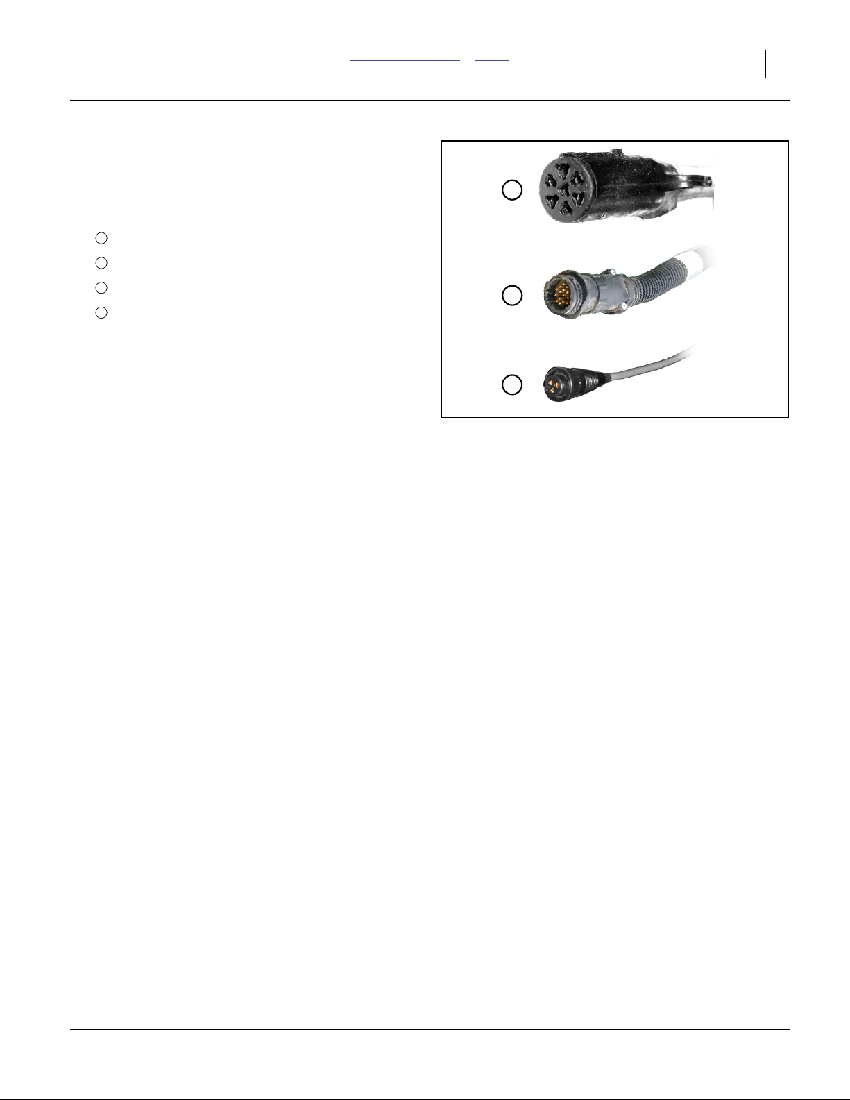
Electrical Hookup
Refer to Figure 7
Your fertilizer applicator is equipped with systems that
require separate electrical connections. For future
reference, note any optional connectors on this checklist.
1
❑ Lighting connector (standard)
2
❑ Console flow harness connector (optional)
3
❑ Console pressure connector (optional)
❑ Console speed connector (optional, and only if
sensor/radar is mounted on implement)
❑ ___________________________
Make sure tractor is shut down with accessory power off
before making connections.
These connections may be made in any order. The key
requirement is that all connections be made prior to
fertilizer applicator movement.
1
2
3
Figure 7
Connector Identification
25236
31083
32019
2012-03-28 Table of Contents Index 407-776M
Page 28
24 NP4000 Table of Contents Index Great Plains Manufacturing, Inc.
Hydraulic Hose Hookup
High Pressure Fluid Hazard:
Shut down tractor before making hydraulic connections.
Only trained personnel should work with system hydraulics.
Escaping fluid under pressure can have sufficient pressure to
penetrate the skin causing serious injury. If an accident
occurs, seek immediate medical assistance from a physician
familiar with this type of injury.
Use paper or cardboard, NOT BODY PARTS, to check for
leaks. Wear protective gloves and safety glasses or goggles
when working with hydraulic systems.
Refer to Figure 8
On implements with more than one hydraulic circuit,
hydraulic hoses are color coded to help you hookup
hoses to your tractor outlets. Hoses that go to the same
remote valve are marked with the same color.
Color Function
Red Lift
Gray Fold, Weight Transfer
Black Hydraulic Pump Drive (Option)
To distinguish hoses on the same hydraulic circuit, refer
to hose label.
• The hose under an extended-cylinder symbol feeds a
cylinder base end, or the return side of a hydraulic
motor.
• The hose under a retracted-cylinder symbol feeds a
cylinder rod end, or the pressure side of a hydraulic
motor.
Use a regular remote and not a dedicated tractor 3-point
remote
Secure hoses and cables so that they have sufficient
slack for hitch movements, but cannot get caught
between moving parts of fertilizer applicator. Failure to
safely route and secure hoses and cables could result in
damage requiring component repair/replacement, and
lost field time.
a
Figure 8
31733
Hose Handles
Machine Function Risk:
The NP4000 weight transfer system requires a tractor with
closed center hydraulics. Open center hydraulics are
incompatible.
a. Some tractors provide a special remote pair at the 3-point hitch arms. On some tractor models, this circuit has specific flow and/or
pressure-sensing behavior intended for certain implements (other than Nutri-Pro®). Nutri-Pro® lift and/or fold and weight transfer may
not function on this type of circuit.
407-776M Table of Contents Index 2012-03-28
Page 29
Great Plains Manufacturing, Inc. Table of Contents Index Preparation and Setup 25
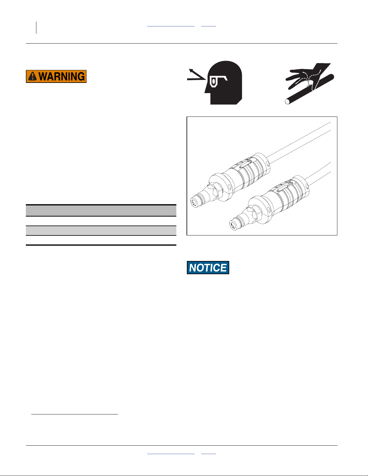
Hydraulic Pump Hookup
The hydraulic motor used is a 7 gpm (23 liter/min.) motor.
If the tractor used does not have the capabilities to adjust
the remotes down to this flow, then a Hydraulic Flow
Divider Kit must be installed so that flow can be
controlled to prevent operating the pump at excessive
speeds. See a Great Plains dealer for more information.
Outlet Port
Inlet Port
If the tractor has only one circuit capable of continuous
flow or only one capable of adjustable continuous flow,
reserve that circuit for the pump, and use another for the
main sprayer functions.
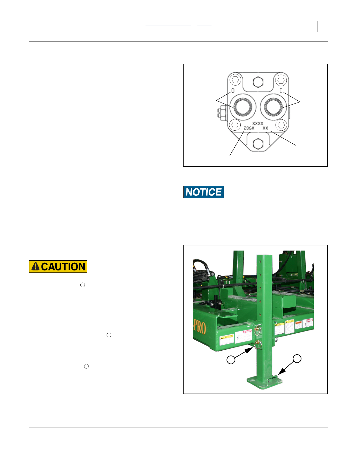
1. Connect the pump hydraulic hoses to suitable tractor
remotes.
Date Code
Refer to Figure 9
2. The pressure hose coming out of the tractor remotes
Motor Model (206N)
must be connected to the motor inlet port:
“I”, Base end on hose label),
and the return line connected to the motor outlet:
Figure 9
Ace Pump Connections
27141
“O”, Rod end on hose label.
3. Before operating, place a stop in the neutral position
for the tractor hydraulics so that the hydraulic lever
can only be moved to the float and down positions.
Refer to the tractor operator manual or tractor dealer
on information for the neutral stop.
4. See page 45 for setting flow rate.
Equipment Damage Risk:
DO NOT move the hydraulic lever into the Neutral position
while the hydraulic pump is running. To do so may cause
damage to the hydraulic pump.
Raise Parking Stands
Refer to Figure 10
Heavy Object Hazard:
Use the lifting handle . Push leg against frame while raising
or lowering. The leg weighs approximately 45 pounds (20 kg).
The leg could cause injury if you lose control of it while
raising or lowering.
1. Use tractor 2-point hitch and the lift-assist circuit to
slightly raise the implement. See “Raising/Lowering
Applicator” on page 35.
2. Remove cotters from pins .
3. Grasp the lifting handle. Use an assistant or
shoulder to hold leg against frame and inside
flanges.
4. Remove the pins .
5. Lift or lower the stand straight up or down.
6. Re-insert pins. Secure with cotters.
2
1
1
1
Figure 10
Parking Stand (Raised)
2
32030
2012-03-28 Table of Contents Index 407-776M
Page 30
26 NP4000 Table of Contents Index Great Plains Manufacturing, Inc.
Leveling Implement
During initial setup and periodically throughout the
season, check that the implement runs level. When
applying fertilizer, the top of the main frame should be
parallel to the ground, and level left to right.
Set Application Depth
Before checking or correcting side-to-side or
front-to-back level, set the application depth (which is
controlled by tool bar height).
®
The Nutri-Pro
application at:
0 to 6 inches (0 to 15.3 cm)
For adjustment, see “Application Height Adjustment”
on page 53.
To check level, lower the implement into the ground in
representative conditions.
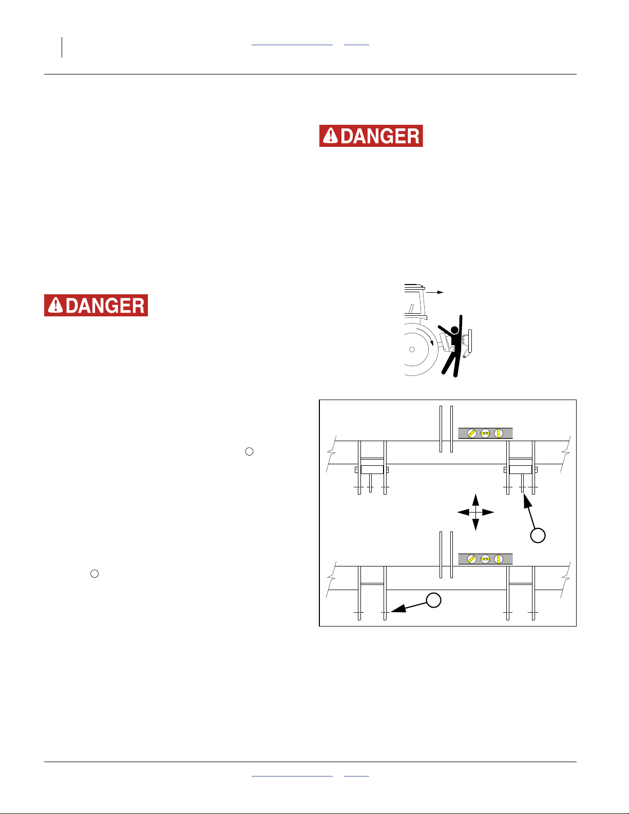
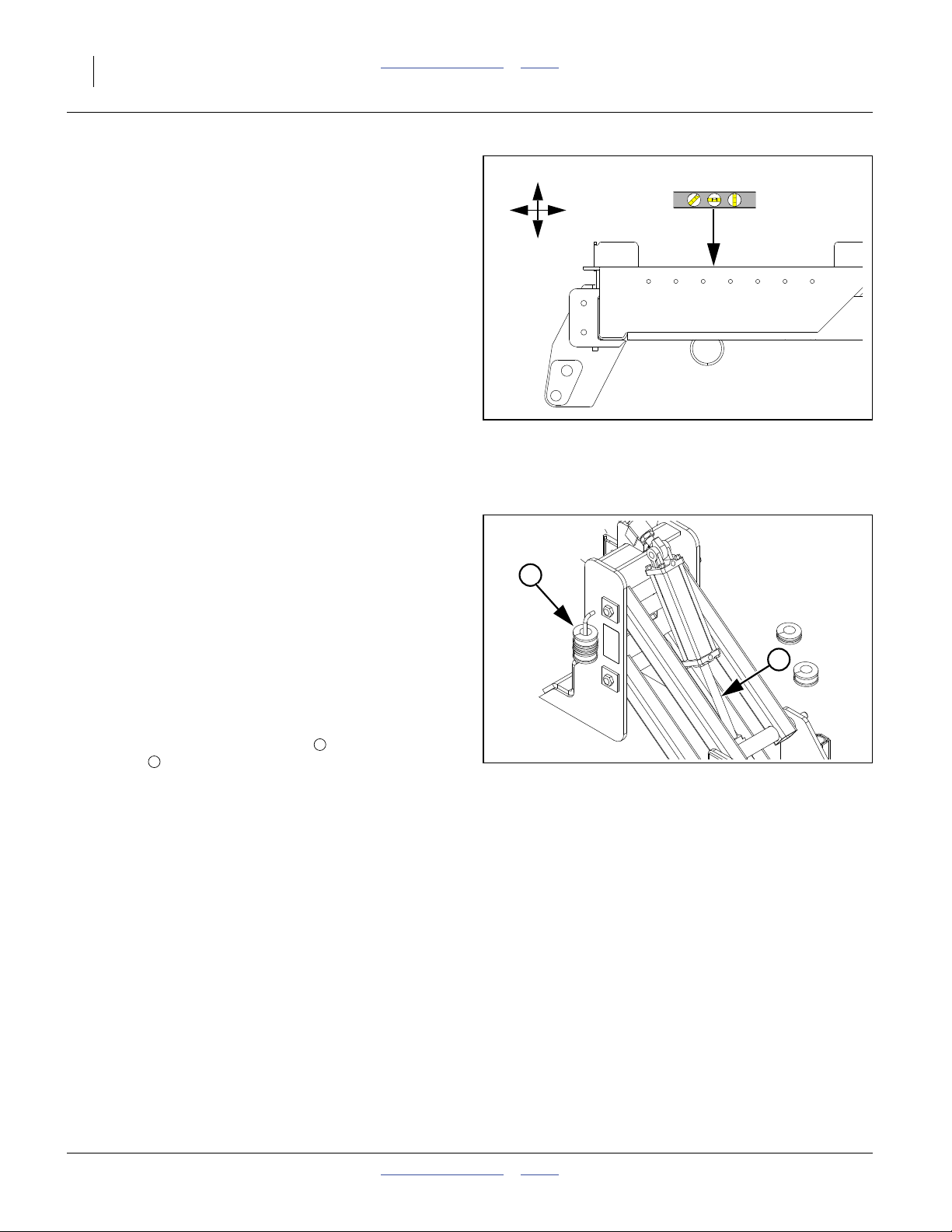
Front-to-Back Level (Spacers)
The rear lift-assist assembly must be set to match the
gauge wheels and 2-point hitch in front. Lift-assist
lowered height is controlled by (provided) spacers on the
lift cylinder rods.
To set:
1. Lower implement until lift assist wheels are just off
the ground.
2. Raise implement until wheels touch ground just
firmly enough to resist spinning.
Refer to Figure 12
(which depicts a lock channel installed on the cylinder rod)
3. Insert a combination of spacers to fill the space on
the rod between the cylinder end and clevis.
4. Raise and lower implement. Pull forward and check
coulter depth and front-to-back level. Adjust spacers
as required to achieve desired application depth.
5. Store unused spacers on any nearby hydraulic hose.
Make sure the spacers cannot slide into positions
that interfere with machine functions.
Liquid Fertilizer is designed for
5
6
F
.epsi
100%
U
B
D
Figure 11
2-Point Leveling
32002
5
6
Figure 12
Lift Assist Lowered Height
31636
407-776M Table of Contents Index 2012-03-28
Page 31

Great Plains Manufacturing, Inc. Table of Contents Index Preparation and Setup 27
Variable Rate Setup (Option)
This topic presumes that the Nutri-Pro®applicator has a
Raven SCS 450 console, speed radar, flow meter,
pressure sensor, and section control valves. It also
presumes that the console has been installed in the
tractor cab per “Console Installation” on page 111.
29
31
If the Nutri-Pro® applicator has dealer- or user-provisioned
controller or metering, carefully follow supplier
documentation for installation, setup, use and maintenance.
This Nutri-Pro® manual (407-776M) cannot describe your
system. Great Plains cannot assume any liability for results
with equipment not supplied by Great Plains.
Before first field use of the SCS 450, it must be
programmed with data specifying the system
configuration, consisting of various “CAL” numbers and
user elected “RATE” numbers. See the Raven SCS 450
manual (or the Calibration Card) for the keystroke
sequence for setting each of these values.
SCS 450: BOOM CAL
In the factory configuration, the hydraulic drive
Nutri-Pro® is connected to one boom (the front boom)
and has one “boom section” (BOOM 1). Because the
center and wings are operated as a single section, the
BOOM CAL number is the swath of the entire implement.
Use the values from the following table.
If using a modified row setup, determine the BOOM CAL
per the Raven SCS 450 manual.
Implement
Model
BOOM CAL
BOOM 1
30
Figure 13
Raven Flow Control and SCS 450
32
32020
NP4000-1236 432 inches (1097 cm)
NP4000-1238 456 inches (1158 cm)
NP4000-1630 480 inches (1219 cm)
NP4000-1630SD 510 inches (1295 cm)
SCS 450: SPEED CAL
A speed sensor connection to the Raven SCS 450 is
required. Perform a calibration per the manuals for the
sensor and the SCS 450.
A speed sensor input allows the SCS 450 to determine
and control application rates at arbitrary field speeds.
Note: The Raven flow control bundles offered by Great
Plains do not include a speed sensor, nor the cable
necessary to connect a Raven-compatible sensor
or radar to the SCS 450. See page 97 for an
available radar kit. See page 97 for harness cables
available from Great Plains or Raven.
2012-03-28 Table of Contents Index 407-776M
Page 32

28 NP4000 Table of Contents Index Great Plains Manufacturing, Inc.
SCS 450: METER CAL
This is the pulse-vs.-rate calibration number for the flow
meter ( in system diagrams in this manual).
Obtain this number from the tag affixed to the meter.
Enter it into the SCS 450 and record on the Calibration
Card.
30
SCS 450: VALVE CAL
This is the response time calibration number for the
control valve ( in system diagrams in this manual).
Obtain this number from the tag affixed to the valve.
Enter it into the SCS 450 and record on the Calibration
Card.
29
SCS 450: PRESSURE CAL
This DATA MENU sequence sets zero for the pressure
transducer ( in system diagrams in this manual).
Perform this operation only when lines are at zero
pressure.
32
SCS 450: RATE 1 CAL
This is your primary desired application rate, typically in
gallons per acre.
SCS 450: RATE 2 CAL
This is your secondary desired application rate, typically
in gallons per acre. If you have no alternate rate
preferred, set this to RATE 1 CAL, so that the control
valve won’t slew if you need to switch to MAN mode.
SCS 450: TANK VOL
Optional. If entered, the liquid fertilizer consumed (as
measured by the flow meter) is continuously subtracted
from this number, and may be used to signal a low tank
alarm. The number needs to be re-entered at each refill.
407-776M Table of Contents Index 2012-03-28
Page 33

Great Plains Manufacturing, Inc. Table of Contents Index Preparation and Setup 29
SCS 450: TIME
Optional. The SCS 450 (which is always in 24:00 hour
time format) defaults to 00:00 (and resets to that after 10
days of inactivity). You may use this menu to set the
actual time.
2012-03-28 Table of Contents Index 407-776M
Page 34

30 NP4000 Table of Contents Index Great Plains Manufacturing, Inc.
Operating Instructions
This section covers general operating procedures.
Experience, machine familiarity and the following
information will lead to efficient operation and good
working habits. Always operate farm machinery with
safety in mind.
Pre-Start Checklist
High Pressure Fluid Hazard:
Escaping fluid under pressure can have sufficient pressure to
penetrate the skin. Check all hydraulic lines and fittings before
applying pressure. Fluid escaping from a very small hole can
be almost invisible. Use paper or cardboard, not body parts,
and wear heavy gloves to check for suspected leaks. If injured,
seek immediate medical attention from a physician familiar
with this type of injury.
This checklist presumes that the nurse tank is not yet
connected.
1. Carefully review “Important Safety Information”
starting on page 1.
2. Lubricate fertilizer applicator as indicated under
“Lubrication and Scheduled Maintenance” on
page 87.
3. Check all tires for proper inflation. See “Tire
Inflation Chart” on page 104.
4. Check all bolts, pins and fasteners. Torque as shown
in “Torque Values Chart” on page 105.
5. Check fertilizer applicator for worn or damaged
parts. Repair or replace parts before going to the
field.
6. Check hydraulic hoses, fittings and cylinders for
leaks. Repair or replace before going to the field.
407-776M Table of Contents Index 2012-03-28
Page 35

Great Plains Manufacturing, Inc. Table of Contents Index Operating Instructions 31
Implement Locks
The Nutri-Pro® NP4000 Applicator is equipped with
several lock systems, which provide safety and/or
operational functions. Manual and manual reset locks
require operator intervention for specific tasks. Automatic
locks require no intervention, but you may need to be
aware of their function.
Lift-Assist Lock Channels
Refer to Figure 14
These 11 inch (28 cm) length manual lock channels
are installed on the rear lift-assist cylinders for
adjustments, transport, parking, storage and raised
servicing. The locks are held in place by a bent pin .
Fully raise the implement (page 35) to install or remove
the channels at the cylinder rods.
When not in use, the channels are stored on tubes on
the caster side faces.
1
2
3
Outer Wing Lock Channels
Refer to Figure 15 and Figure 16
These 201⁄4inch (51.4 cm) manual lock channels are
installed on the outer wing fold cylinders only for field
operations. They (and the inner wing locks) provide stops
limiting fold during lift for field turns. The locks are held in
place by a bent pin . See “Unfolding and Folding” on
page 37.
Fully unfold the implement (page 37) to install or remove
these locks.
Note: If the outer wing has not fully unfolded due to
ground contact, pull forward to bring wings level.
When not installed, the outer wing locks may be stored at
the mounting tab on the wing rest stops.
Note: Be sure to use the 201⁄4inch (51.4 cm) locks onthe
outer wing cylinders, and not the 11 inch (28 cm)
lift-assist locks.
3
4
2
1
3
Figure 14
Lift-Assist Cylinder Lock Channel
3
Figure 15
Outer Wing Lock Channel
1
2
1
32373
1
2
32368
Wing Lock Pins
Refer to Figure 16
These pins are manually inserted after fold, both as a
safety precaution, and to minimize wing-cradle impacts
during transport.
When not engaged, the pins are stored in tubes at the
base of the rest weldment.
See “Folding” on page 39.
2012-03-28 Table of Contents Index 407-776M
1
2
Figure 16
Wing Lock Pins
2
4
32374
Page 36

32 NP4000 Table of Contents Index Great Plains Manufacturing, Inc.
Inner Wing Lock Channels
Inner Locks in Transport
Refer to Figure 17
These manual-reset lock channels ( and ) are
permanently installed on the inner wing fold cylinder
clevises. These locks (and the outer wing locks) provide
stops limiting fold during lift for field turns.
The rear cylinder lock , equipped with a spring plunger,
also has a separate use during initial unfold, where it
limits inner wing travel to eliminate risk of opener
damage.
During pre-fold, transport and wings-folded storage, both
lock channels are retained by a pin in a holder .
Inner Locks During Unfold
Refer to Figure 18
1. Withdraw the pin , releasing at least the
spring-plunger lock channel .
2. Swing the spring plunger toward implement
center, over the stroke control valve , and rest the
spring-load bolt on the cylinder body.
3. Rest the standard lock channel on the front
cylinder face.
2
3
1 2
3 4
2
5
6
1
2
Figure 17
Inner Wing Locks: Transport
2
5
4
3
1
34107
3
Inner Wing Locks After Unfold
Refer to Figure 19
During the initial unfold, the spring-plunger aligns with
the cylinder axis. The spring-loaded bolt engages an
actuator on the stroke control valve, stopping inner wing
motion slightly above wings-level.
5
6
Figure 18
Inner Wing Locks: Pre-Unfold
5
Figure 19
Inner Wing Locks: Initial Unfold
34108
34104
407-776M Table of Contents Index 2012-03-28
Page 37

Great Plains Manufacturing, Inc. Table of Contents Index Operating Instructions 33
Inner Wing Locks in Field
See “Raising/Lowering Applicator” on page 35 for
complete field lift and lower instructions.
Refer to Figure 20
5
1. After initial unfold is complete (including outer wings,
see page 37), set the fold circuit to Neutral.
Crushing Hazard:
Keep body parts clear of, and not beneath blades and knives
when performing the next step. If the hydraulics are damaged
or incorrectly configured, some vertical motion could occur
when the spring-plunger is disengaged.
2. Rotate the spring-plunger assembly outward onto
5
Figure 20
Inner Wing Locks: Field
34105
the lock channel.
Note: Normally, nothing happens when the plunger is
disengaged. The actuator of the stroke control
valve remains depressed until the next step.
3. As needed, set or reset the height of the wing gauge
wheels.
4. Retract the fold circuit slightly. This resets (releases)
the stroke control valve.
5. Extend the fold circuit until the gauge wheels are in
ground contact.
6. Set the fold circuit to Float.
Inner Wing Locks Pre-Fold
See “Unfolding and Folding” on page 37 for complete
unfolding and folding instructions.
5
1
Refer to Figure 21
1. As needed, extend the fold circuit to free the inner
wing lock channels. If the inner wing is partially
raised, the channels may be captured by the bolts at
the cylinder faces.
2. Remove the pin at the holder.
3. Rotate the front lock channel fully outward.
3
1
3
4. Rotate the rear lock channel outward, while rotating
the spring-plunger assembly inward, until the rear
lock channel rests in the holder.
5. Secure both lock channels with the pin .
5
Figure 21
3
Inner Wing Locks: Pre-Fold
34106
2012-03-28 Table of Contents Index 407-776M
Page 38

34 NP4000 Table of Contents Index Great Plains Manufacturing, Inc.
Outer Wing Fold Latches
Refer to Figure 22
These latches are automatic, and should never require
operator action. The latches couple the outer wing to the
inner wing when folded, preventing movement of the
outer wing during transport (the two outer wings might
otherwise be able contact each other in unusual
circumstances).
When unfolded, the latch pivots out and down
(disengaged). During fold, the outer wing folds first, until
the stop posts contact each other. As the inner wing
then folds, and passes vertical, the latch swings into
engagement on the pins of the outer wing stop post.
At the start of unfold, the latches restrain the outer wings,
causing the inner wings to unfold first. As the inner wings
near the ground, the latches fall away, allowing the outer
wings to unfold.
2
1
3
2
2
1
3
Figure 22
Outer Wing Latch
32372
407-776M Table of Contents Index 2012-03-28
Page 39

Great Plains Manufacturing, Inc. Table of Contents Index Operating Instructions 35
Raising/Lowering Applicator
Operate the tractor hitch in “position” or “depth” control
mode, regardless of implement hitch type.
The implement may be raised and lowered while folded.
Raise For Transport (Folded)
These steps presume an implement parked or stored
folded, already raised, but on lift-assist locks and parking
stands.
1. Verify that lock channels are installed on the
lift-assist cylinders (page 31).
2. Raise the tractor 3-point hitch just enough to lift the
parking stand bases off the ground. Set the hitch
circuit to Neutral. Shut off the tractor.
3. Raise the parking stands (page 25).
Gradual Crushing Hazard:
Do not rely on hydraulic pressure alone to keep the implement
raised. Use parking stands (page 25) and transport/lift locks
(page 31) when working around a raised implement. The
tractor hitch may settle. The bypass orifices in the implement
lift-assist re-phasing system cause it to slowly lower.
Equipment Damage Risk:
Do not fully fold or fully unfold while lowered. Perform
complete fold and unfold only when fully raised. When
lowered, the wing coulters near the wing pivots may be
damaged by bending or ground dragging.
Raise Pre-Folding (Unfolded)
These steps presume an implement parked or stored
unfolded, already raised, but on lift-assist locks at rear,
on extended gauge wheels at wing tips, and on parking
stands at hitch.
1. Verify that lock channels are installed on the
lift-assist cylinders (page 31), on inner wing fold
cylinders (page 31) and on outer wing fold cylinders
(page 31).
2. Retract the fold circuit until all wing sections are
stopped by lock channels (page 31). Set fold circuit
to Neutral.
3. Raise the tractor 3-point hitch enough to lift gauge
wheels, coulters, and the parking stand bases off the
ground. Set the hitch circuit to Neutral. Shut off the
tractor.
4. Raise the parking stands (page 25).
5. Start the tractor. Extend the fold circuit until the
wings are level, or until all wing lock channels are
free. Set fold circuit to Neutral. Shut off tractor.
6. Set inner wing lock channels for pre-fold (page 33).
Remove and store outer wing lock channels
(page 31).
Field Lift
Figure 23
32367
Partial Fold to Lock Channels
These steps presume an unfolded implement in field
configuration (lift-assist locks out, spacers in, wing lock
channels in, coulters in ground).
1. Set the fold circuit to Retract. Wing sections fold
against the lock channels (see Figure 23 above).
2. Set the lift-assist circuit to Extend.
3. Raise the tractor 3-point hitch.
4. When partial fold and lifts are completed, set all
three circuits to Neutral for extended turns or field
moves.
With some experience this lift can be done with near
simultaneous circuit operation, and done while moving.
2012-03-28 Table of Contents Index 407-776M
Page 40

36 NP4000 Table of Contents Index Great Plains Manufacturing, Inc.
Lower While Folded
These steps presume that the intention is parking or
storage, on lift-assist locks and parking stands.
1. Verify that the lift lock channels are installed on the
lift-assist cylinders (page 31).
2. Retract the lift-assist circuit to lower the lift-assist
cylinders onto their locks.
Tip-Over and Crushing Hazard:
Never unhitch without using parking stands, particularly while
folded. A folded implement without parking stands deployed
will tip forward immediately upon unhitching. Anyone at the
hitch or in the tractor may be seriously injured or killed. The
tractor cab may be crushed.
3. Raise the tractor three-point hitch until the implement
mainframe is level front-to-rear, or the front is slightly
higher than the rear. Set the hitch circuit to Neutral.
Shut off the tractor.
4. Deploy the parking stands. Pin them so that the
frame will be level when lowered onto the stands.
5. Start the tractor. Lower the tractor hitch until the
implement is supported by the parking stands.
Equipment Damage Risk:
Although it is possible to fully lower the implement while
folded (with parking stands in place or while hitched), this is
not recommended. This can place the full weight of the
machine on the center coulters, exceeding their spring
capability.
Lower While Unfolded
These steps presume that the intention is to park, store
or service the implement, and that lift-assist lock and
parking stands are to be used. For field lower and field
adjustments, see topic “Field Lower” following.
1. Verify that all lock channels are in place on wing fold
cylinders.
2. To keep all coulters off the ground when unfolded
and lowered, crank the gauge wheels to full
extension (page 55).
3. Retract the fold circuit until inner and outer wing fold
is stopped by lock channels.
4. Set the fold circuit to Neutral.
5. Extend the lift-assist circuit to fully raise the
implement at rear. Set circuit to Neutral.
6. Raise the tractor three-point hitch until the implement
mainframe is level front-to-rear, or the front is slightly
higher than the rear. Set the hitch circuit to Neutral.
Shut off the tractor.
7. Install the lock channels at the lift-assist cylinders
(page 31).
8. Deploy the parking stands. Pin them so that the
frame will be level when lowered onto the stands.
9. Start the tractor. Retract the lift-assist circuit until the
cylinders rest on the lock channels.
10. Lower the hitch until the implement rests on the
parking stands at front.
11. Extend the fold circuit until the gauge wheels touch
the ground, then set the circuit to Float.
Field Lower
These steps are for lowering in the field after initial
line-up and after turns. Lift-assist lock channels are
presumed to have been replaced by spacers. The
down-pressure/weight transfer system is presumed to be
adjusted.
The key objectives for an optimal lowering are:
• avoid side loads on coulter discs or applicator tips by
avoiding lowering with drooped wing tips, and
• avoid applicator plugging by avoiding any reverse
motion of the applicator tips at the ground.
Being in slow forward motion during lower avoids both of
these risks. The following instructions presume a
lowering while stationary.
1. Check that wings are partially folded against locks,
or at least level. If they are drooping, retract the fold
circuit to correct.
2. Lower the tractor 3-point hitch to the preset field
height. Set the hitch circuit to Position or Depth
Control.
3. Retract the lift-assist circuit until the cylinders rest on
the spacers. Set the lift-assist circuit to Float.
Note: You may also lower the hitch and lift-assist
simultaneously, but avoid lowering the lift-assist
before the hitch.
4. Pull forward.
5. Extend the fold circuit to level the wings. Set the
circuit to continuous for weight transfer.
407-776M Table of Contents Index 2012-03-28
Page 41

Great Plains Manufacturing, Inc. Table of Contents Index Operating Instructions 37
Unfolding and Folding
Unfolding (At Field)
These instructions presume the implement has just
completed transport, is raised, and transport locks are
installed. It is being unfolded for field use.
1. Remove the wing lock pins (page 31).
2. Extend the lift-assist circuit to fully raise the
implement and free the lift-assist lock channels.
3. Un-pin all four inner wing lock channels (page 32).
Swing the spring-plunger assemblies onto their
respective fold cylinder bodies (page 32).
4. Extend the fold circuit to unfold the wings.
5. Set all circuits to Neutral. Shut off the tractor.
6. Install the outer wing lock channels (page 31)
7. Swing the spring-plunger assemblies outward onto
their lock channels (page 32).
8. Remove the lift-assist lock channels (page 31).
Install the spacers (page 26).
9. If wing gauge wheels were extended, crank them to
field height (page 55).
10. Retract the fold circuit slightly to reset the stroke
control valve.
Figure 24
32367
Normal Unfold Sequence
Notes about normal unfold:
• Inner wings unfold first. The outer wings are
constrained by the wing latches (page 34).
• Inner wing lock channels (page 32, not shown above),
if correctly preset, engage during inner wing unfold.
• Outer wings unfold last. The wing latches release just
before the inner wings are level.
2012-03-28 Table of Contents Index 407-776M
Page 42

38 NP4000 Table of Contents Index Great Plains Manufacturing, Inc.
Unfolding (Parking, Storage, Service)
To unfold, off field, for parking, storage or servicing,
unfold with the center section fully raised.
1. Hitch to a suitable tractor (page 22).
2. Extend the lift-assist circuit to fully raise the
implement rear.
3. Raise the tractor 3-point hitch.
4. If lift-assist lock channels are not installed, set
circuits to Neutral. Shut off the tractor. Remove
spacers (page 26). Install lock channels (page 31).
Re-start the tractor.
5. Un-pin all four inner wing lock channels (page 32).
Swing the spring-plunger assemblies onto their
respective fold cylinder bodies (page 32).
6. Extend the fold circuit to unfold the wings.
7. Set all circuits to Neutral.
8. Install the outer wing lock channels (page 31)
9. Swing the spring-plunger assemblies outward onto
their lock channels (page 32).
10. Retract the lift circuit slightly to reset the stroke
control valve. Extend the circuit to set the wings
level.
11. Shut off the tractor.
12. Unless using blocks or stands under wings, fully
extend wing gauge wheels (page 55).
Figure 25
Normal Unfold Sequence
32367
13. Deploy parking stands at desired or maximum
height.
14. Start the tractor. Retract lift circuit to lower lift
cylinders onto lock channels. Set lift circuit to Float.
15. Lower the 3-point hitch until the implement rests on
the parking stands at front.
16. Extend the fold circuit until the gauge wheels contact
the ground. Set the fold circuit to Float.
Notes about normal unfold:
• Inner wings unfold first. The outer wings are
constrained by the wing latches (page 34).
• Inner wing lock channels (page 32, not shown above),
if correctly preset, engage during inner wing unfold.
• Outer wings unfold last. The wing latches release just
before the inner wings are level.
407-776M Table of Contents Index 2012-03-28
Page 43

Great Plains Manufacturing, Inc. Table of Contents Index Operating Instructions 39
Folding
These instructions presume that the implement is
unfolded and lowered.
1. Verify that the wing lock pins (page 31) are not in the
wing rest cradles. Typically they are in storage tubes.
2. Set the fold/down-pressure circuit to Neutral.
3. Raise the implement (page 35). Set the lift and hitch
circuits to Neutral.
4. As needed, use the fold circuit, bring the wings to
near or slightly below level. Set fold circuit to Neutral.
Shut off tractor.
5. Remove spacers (page 26). Install lift-assist cylinder
locks (page 31).
6. Remove and store outer wing lock channels
(page 31).
7. Rotate inner wing lock channels into holders and pin
(page 33).
8. Start tractor. Retract fold circuit.
9. Watch outer wing sections. In a normal fold
(Figure 26), the outer wings fold first.
If the outer wings do not fold first (as in Figure 27),
STOP. Perform step 4, 6 and step 8 above.
Electrocution and Overhead Collision Hazards:
Do not fold with outer wings locks installed. Remove outer
wings locks before folding. With locks installed, the folded
implement may be over 21 feet (6.2 m) high. This dramatically
increases the risk of electrocution from overhead lines, with or
without direct contact. It is also too high for safe transport.
10. When both wings are seated in the wing rest cradles,
set the fold circuit to Float.
11. Retract lift circuit to lower lift-assist cylinders onto
lock channels. Set lift circuit to Float. Shut off tractor.
12. Install wing pins (page 31).
For parking/storage/service, lower the implement onto
parking stands.
Figure 26
Normal Fold Sequence
Figure 27
Abnormal Fold
32367
32367
2012-03-28 Table of Contents Index 407-776M
Page 44

40 NP4000 Table of Contents Index Great Plains Manufacturing, Inc.
Transport
Loss of Control Hazards:
Never transport a 2-point implement unless the tractor is
properly ballasted to provide adequate weight on the steering
wheels. A heavy 2-point implement can dangerously reduce
steering control. Check your tractor manual for ballasting
requirements. A normal turn could result in an accident and
serious injury or death.
Do not transport applicator with material in on-board tanks.
Add liquid fertilizer at field. Full tanks add 7200 pounds
(3270 kg) to the weight of the implement, almost all of it borne
by the tractor 2-point hitch. This can substantially reduce
tractor steering and does increase braking load. The
implement rear casters are free to swivel, and cannot provide
protection against under-steer in turns.
Loss of Control Hazard:
Never use the applicator to tow a nurse tank on public roads.
Tow the tank to the field with a separate vehicle. The
applicator cannot provide sufficient lateral control of a trailing
cart at highway speeds. The total weight of the train can also
easily exceed the steering and/or braking capability of the
tractor. A tank upset could occur during normal highway
maneuvers. The resulting accident or spill could cause serious
injury or death.
Braking and Loss of Control Hazard:
Do not exceed 20 mph (32 kph).
Loss of Control Hazard:
Never tow a 2-point implement that weighs more than 150% of
the tractor (transport tractor must weigh at least 67% of
implement). Ensure that the towing vehicle is adequate for the
task. Using an inadequate tow vehicle is extremely unsafe, and
can result in loss of control, serious injury and death.
Tractor weight matters. For field configuration (after
transport), tractor must weigh at least 150% of the loaded
implement plus any loaded nurse tank. This tractor weight
requirement is substantially higher than for transport.
Typicala NP4000 Weights by Configuration
NP4000-1630 NP4000-1630(SD) NP4000-1236 NP4000-1238
Configuration
Tankless Tankless Tankless Tankless
Dual Tank Dual Tank Dual Tank Dual Tank
Minimum 9080 lbs. 10580 lbs. 9328 lbs. 13468 lbs. 8820 lbs. 13666 lbs. 9424 lbs. 10924 lbs.
(4119 kg) (4799 kg) (4231 kg) (6109 kg) (4001 kg) (6199 kg) (4275 kg) (4955 kg)
Maximum 17235 lbs. 18255 lbs. 13998 lbs. 18503 lbs. 15351 lbs. 17197 lbs. 16546 lbs. 18046 lbs.
Empty
(7818 kg) (8280 kg) (6350 kg) (8393 kg) (6963 kg) (7800 kg) (7505 kg) (8186 kg)
Maximum 25455 lbs. 25703 lbs. 24397 lbs. 25246 lbs.
Full
Minimum: single coulter, no pump, no rear hitch, single manifold
Maximum: triple coulter, ground drive pump, rear hitch, tines, dual manifold, weights, side dress (1630 only)
a. Weights are approximate, and can vary by hundreds of pounds based on options, accessories and user modifications.
407-776M Table of Contents Index 2012-03-28
(11546 kg) (11659 kg) (11066 kg) (11452 kg)
32351W
Page 45

Great Plains Manufacturing, Inc. Table of Contents Index Operating Instructions 41
Transport Steps
Know your implement weight. See page 40 for a list of
approximate weight of various configurations.
If tractor capabilities are marginal, check actual weight of
implement at a scale.
1. Check that fertilizer applicator is securely hitched to
a sufficient tractor (page 22)
2. Verify correct operation of lights.
3. Raise fertilizer applicator (page 35).
4. Install lift cylinder locks (page 31).
5. Fold applicator if unfolded (page 37).
6. Plan the route. Avoid steep hills.
7. Always have lights on for highway operation.
8. Do not exceed 20 mph (32 kph). Comply with all
national, regional and local laws when traveling on
public roads.
9. Remember that the fertilizer applicator may be wider
than the tractor. Allow safe clearance.
10. Transport slowly over uneven or rough terrain.
Final Implement Setup
Prior to hitching nurse tank, make and check final
implement adjustments. This could include:
• Application depth, page 53.
• Application Rate, page 64.
• Row cleaner adjustments, page 63.
• Make a dry run to check implement functions, running
depth and sealing.
For nurse cart hitching, the implement may be raised or
lowered, folded or unfolded. However, raised and folded
hastens departure if any nurse tank problems are
discovered before cart hitching.
2012-03-28 Table of Contents Index 407-776M
Page 46

42 NP4000 Table of Contents Index Great Plains Manufacturing, Inc.
Loading Materials
Filling Tanks
The tanks may be loaded from the quick-fill inlet, or from
the lids (page 43).
If the fertilizer solution has any tendency to settle,
sediment, gel, coagulate, precipitate or stratify, load
material immediately prior to application. The tank
system has no agitators for sustaining suspensions.
Apply fertilizer soon after material loading. Clean out
unused materials promptly. Fertilizer allowed to remain in
the tanks for an extended period can settle, resulting in
excessive or insufficient concentrations during
application. System plugging can also occur.
1. Hitch the implement to a tractor. Filling an unhitched
implement is not recommended, as it can increase
parking stand loads above the bearing capacity of
the soil.
2. Inspect the tanks from the lids.
3. Drain excess condensation from the tank, so that this
water does not dilute the material to be loaded. See
“Material Clean-Out” on page 79.
4. Flush the tank if there is other residue present.
Tank Quick-Fill
Refer to Figure 28 and Figure 3 or Figure 4 on page 17 or 18
5. Position the implement on level ground, or tanks may
fill unevenly.
6. Connect the nurse-tank hose to the quick-fill
coupler located at the left end of the left tank.
Lock hose in place with cam-lock levers.
7. Open the discharge valve ( , not shown) of each
tank to be filled. If filling must be performed on
unlevel ground, fill one tank at a time.
8. Set the selector valve to “FILL” (handle arrow
pointing forward, toward elbow from inlet).
9. Open shut-off valve at quick-fill coupler.
10. Open any supply valve and fill tanks. Tanks are
marked with fill levels.
11. Close valve at supply, then quick-fill coupler, and
disconnect the nurse tank hose.
12. Set selector valve to OFF, or to PUMP if applying
immediately.
16
13
15
17
Agricultural Chemical Hazards:
Observe safety precautions specified by material suppliers.
Some chemicals can cause serious burns, lung damage and
death. Avoid contact with skin or eyes. Avoid prolonged
breathing of chemical fumes. Wear respirator and other
protective equipment as required by chemical manufacturer.
Seek medical assistance immediately if accident occurs. Know
what to do in case of an accident.
System Plugging Risk:
Use only pre-mixed liquid fertilizer. Fill tanks at field,
immediately prior to application. Do not use dry mixes. Do not
leave material in tanks for extended periods.
17
15
16
18
Figure 28
Inlet and Selector Valve
32082
407-776M Table of Contents Index 2012-03-28
Page 47

Great Plains Manufacturing, Inc. Table of Contents Index Operating Instructions 43
Tank Lid Fill
Employ two persons for top fill; one to secure the hose at
the tank, the other to control a supply line shut-off valve.
These steps presume completion of step 1 through
step 5 on page 42.
Refer to Figure 29 and Figure 3 or Figure 4 on page 17 or 18
13. Close selector valve (or set to PUMP; there is no
15
risk of material leakage through the boom until the
pump is operating).
14. Open both tank discharge valves to the selector
13
valve, if cross-filling from one tank to the next is
Chemical Hazard - Tank Lid:
For top loading, wear gloves and any other protective
equipment indicated for any materials that have ever been
used in the tank (not just the materials recently loaded or
presently being loaded). Normal operations splash material on
the underside of the lid. It is likely to be coated with residues
that could be highly concentrated, whether dry, damp or wet.
Remove the lid slowly to avoid throwing off material toward
yourself.
desired.
15. Open the lid of the tank to be filled.
12
The tank lid completely unscrews for a 7 in (18 cm)
opening.
16. Insert the supply hose.
17. Open the supply line valve. Monitor tank level. Fill to
desired level. Close supply valve.
18. Remove hose. Close and secure the tank lid. The lid
has twin threads. Make sure that both are evenly
engaged when tightening the lid, and that the lid is
fully seated.
12
Figure 29
Tank Lid Closed and Open
32083
2012-03-28 Table of Contents Index 407-776M
Page 48

44 NP4000 Table of Contents Index Great Plains Manufacturing, Inc.
Hitching Nurse Tank
Hitch a nurse tank to the implement only at the field, and
not prior to transport.
Mechanical Cart Hitching
1. Spot the implement to avoid reverse moves after cart
hitching.
Refer to Figure 30
2. Bring the implement rear hitch tongue and nurse
tank cart tongue into close proximity (a few inches).
3. Push down on the red tongue release handle .
This frees the implement rear hitch tongue to
extend 7 inches (17.8 cm) to the rear, and 9 inches
(23 cm) to either side, to assist with cart tongue
alignment.
4. Align the cart clevis hitch with the implement pull
bar. Insert and secure the 1 inch (2.6 cm) hitch pin.
5. Securely attach the cart’s safety chain(s) to the
hitch chain anchor(s) .
6. Optionally re-seat the implement rear hitch tongue,
at this time, by using the tractor to move the
implement backward several inches, until the latch
on the hitch re-engages.
46
44
43
45
47
44
43
17
16
45
49
47
50
Making Nurse Tank Connections
1. Close shut off valves on all hoses of both tank
and implement .
2. Route tank supply hose to implement inlet .
Allow ample slack for tight field turns and uneven
ground. Do not leave so much slack that the hose
can reach the ground.
3. Remove plug from implement inlet, and any cap on
tank supply hose.
4. Inspect and clean connector fittings.
5. Mate connectors of tank and implement supply
hoses. Fold cam levers forward to lock. Leave valves
closed.
6. If the tank has additional hoses, secure them at the
tank.
17
50 16
49
Figure 30
Implement-Cart Hitch
Equipment Damage Risk:
Use only pre-mixed liquid fertilizer.
46
32349
407-776M Table of Contents Index 2012-03-28
Page 49

Great Plains Manufacturing, Inc. Table of Contents Index Operating Instructions 45
Fertilizer Operation
For an aftermarket pump system, consult the pump or
system documentation. These pages describe the
available Great Plains systems. See page 14 through
page 20 for callout references.
Ground Drive Operation
The piston pump is ground driven. When the
applicator is lowered and in motion, the pump operates,
and fertilizer is applied based on the drive Range
sprocket, and pump adjuster dial setting .
Hydraulic Drive Operation
The centrifugal pump is driven by an integrated
hydraulic motor. The output of the pump is under
pressure whenever the hydraulic motor circuit is
activated. Rate is regulated by a flow control valve ,
and monitored by a flow meter , both connected to a
Raven SCS 450 console (or other compatible Raven
console).
Boom Operation
The liquid fertilizer boom system is designed to operate
(ideally) between 15 and 40 psi. Several system
elements affect system pressure, and need initial setup,
periodic maintenance, and adjustment.
Start-Up Preparation (Either Pump)
1. Check that ample fertilizer has been loaded into the
tanks. The liquid level must be higher than the
hydraulic pump for pump priming. Close and cap or
plug any tank fill inlet valves (such as in the Great
Plains plumbing system).
2. Check that tank valves (such as discharge, transfer,
selector) are configured and ready for use. In the
Great Plains tank plumbing system, this would be:
13
tank discharge valves open to selector valve
15
selector valve open to tanks and pump
3. On suitable ground, raise the applicator.
19
27
30
20
17
29
Possible Agricultural Chemical Hazard:
Avoid contact with skin or eyes. Wear proper protective
equipment as required by chemical manufacturer. Avoid
prolonged breathing of chemical fumes. Wear respirator as
required by chemical manufacturer. Some chemicals will cause
serious burns, lung damage, and death. Seek medical
assistance immediately if accident occurs. Know what to do in
case of accident.
Pump No-Flow Risk:
The hydraulica pump must be primed. The liquid level in the
tank must be at a higher elevation than the pump inlet. The top
of the pump must be fitted with either an air bleed line to the
top of a tank, or a manual bleed valve. The bleed line must be
open at least until the pump if filled with material.
When tanks and pump are ordered, the factory configuration
includes an air bleed line from the hydraulic pump to one of
the tank lids. User-configured systems must make provision for
pump priming.
a. The ground drive pump is a positive displacement piston
type, and normally self-primes at any liquid level.
2012-03-28 Table of Contents Index 407-776M
Page 50

46 NP4000 Table of Contents Index Great Plains Manufacturing, Inc.
Ground Drive Pump Start-Up
4. Check ground drive sprocket setup (page 72).
5. Set rate on pump adjuster dial.
Refer to Figure 3 on page 17 or Figure 4 on page 18
6. If relief valve has not been previously adjusted,
25
perform initial setting per page 71.
Prime the Ground Drive System.
7. Wearing gloves, manually rotate the ground drive
wheel until material appears at the applicator tubes.
Begin field operations.
The pump automatically operates when the implement is
lowered to ground contact and in motion. The pump
automatically stops when the implement is raised for
turns.
Hydraulic Drive Start-Up
Prior to first use, determine the hydraulic remote circuit
flow rate setting per the procedure on page 73.
4. Set console MASTER switch OFF.
5. Set console POWER switch ON.
6. Select FLOW CONTROL RATE1 or RATE2 as
desired, and verify rate setting.
7. Set console BOOMSa switch 1 ON.
8. Set the flow rate for the hydraulic remote circuit as
established by the procedure on page 73.
9. Activate the circuit by moving the lever to Retract.
You may hear the pump operating, but with the
MASTER switch off, no material flows to rows.
10. Set the MASTER switch ON. Check for material flow
at the applicators. Prime second hydraulic pump as
required.
11. Begin field operations. Monitor the fertilizer pressure
gauge (or PSI display on optional console).
Field Operations (Either Pump)
12. Monitor the fertilizer manifold pressure (gauge or PSI
display on optional console).
13. Mind the fertilizer tank levels while planting, both to:
a. confirm expected consumption rate, and;
b. avoid running the pump dry.
14. If residual fertilizer is not recovered at end of
planting, apply it to the last field planted.
15. Clean out fertilizer system per page 79.
Sharp Object Hazard:
Ground Drive: Exercise caution when near and handling the
ground drive wheel. Wear gloves. The tines may be sharp.
Equipment Damage/Material Misapplication Risks:
Ground Drive: Do not run the pump dry. With all drive chains
in place, the ground drive pump always runs when the
applicator is lowered and in motion. Air rapidly damages the
pump. Keep fluid in pump at all times. Disconnect a chain
when not applying fertilizer.
Hydraulic Drive: Do not run the pump dry. The pump runs
when the remote circuit is active, regardless of applicator
status. Air can damage the pump. Keep fluid in the pump at all
times. Set remote to Float when not applying fertilizer.
If fertilizer is exhausted prematurely, reload fertilizer
immediately. If fertilizer is not available, load clean water,
continue planting with pump operating (to flush system), and
disconnect pump drive before water is exhausted (to keep
pump wet).
Pauses and Turns
Ground Drive Pauses and Turns
When the implement is stopped, or lifted, the pump
stops. The boom is still pressurized, but this bleeds down
to 8 psi very quickly (seconds), at which point the nozzle
clamp check valves close off flow to the rows.
Hydraulic Drive Pauses and Turns
If the implement has the optional hydraulic drive system,
pauses cause the speed sensor to report zero speed,
which causes the console to close the flow control valve.
Set the pump hydraulic remote to Float is stopping for
and extended period.
For turns and field moves, set the MASTER switch OFF
to avoid material loss. If the factory configuration of the
plumbing has been modified for section control, use the
BOOM switches as desired for point row applications.
a. The factory configuration uses only Valve 1. If the plumbing system has been modified after delivery, it may be necessary to also
engage BOOMS switches 2 or 3.
407-776M Table of Contents Index 2012-03-28
Page 51

Great Plains Manufacturing, Inc. Table of Contents Index Operating Instructions 47
Monitor Operation (Option)
Refer to Figure 31
With the optional hydraulic drive pump, the optional
SCS 450 console monitors fertilizer flow, field speed, and
manifold pressure. It operates the control valve to deliver
fertilizer at your desired rate.
Once setup for the applicator and preferences, and
configured for the rates/limits, the monitor is typically
used in the “RATE 1” or “RATE 2” FLOW CONTROL
modes.
Starting Application with Console
1. Enter the tractor cab.
Refer to Figure 31
2. At the console, set the POWER switch ON.
3. Set the MASTER switch to ON.
4. Set the BOOMS 1 switch
a
on to ON
all others don’t-care (suggest OFF).
5. Select the desired RATE preset.
6. Engage the remote for the hydraulic drive pump.
Advance lever to preset for +35% of desired rate.
7. Lower implement to operating depth (if not already
lowered) and begin first pass.
See SCS 450 manual for monitor operation details.
.eps
33.0%
Figure 31
Typical Application Screen
32105
a. The factory configuration uses only Valve 1. If the plumbing system has been modified after delivery, it may be necessary to also
engage BOOMS switches 2 or 3.
2012-03-28 Table of Contents Index 407-776M
Page 52

48 NP4000 Table of Contents Index Great Plains Manufacturing, Inc.
Ending Application
1. Ground Drive: If possible, plan final passes so that
they occur prior to tank run-out. This keeps the pump
wet. If you do exhaust the material, refill with water.
2. At completion of application, apply almost all of the
remaining fertilizer on the last field. Refill the tank
with clean water.
3. Set application rate to maximum to shorten the
remaining steps:
• Ground Drive: Exchange the ground drive driving
sprocket to obtain High Range (page 72).
• Ground Drive: Set the pump dial to 10 (page 72).
• Hydraulic Drive: Set the console (Option) for
maximum rate.
4. Apply this water to the final field to flush the pump
and boom.
5. Close shut-off valves on both sides of all hose
connections.
6. Disconnect all cam-lock couplers from the tank to the
implement.
For a trailing nurse tank cart:
7. Disconnect the safety chains.
8. Remove the hitch pin. Move the trailer hitch off the
implement’s draw bar.
Piston Pump Damage Risk:
Ground Drive: When configuring the pump for high rates,
check the chart, slide chart or CDS-John Blue web calculator
to determine the maximum field speed that stays at or below
the pump’s maximum rated rpm.
407-776M Table of Contents Index 2012-03-28
Page 53

Great Plains Manufacturing, Inc. Table of Contents Index Operating Instructions 49
Field Set-Up Checklists
Use the following tables to develop a final checklist for
your tractor/fertilizer applicator configuration. Additional
or fewer steps may be necessary depending on tractor
features, fertilizer applicator options and planting
accessories.
Mechanical Checklist (Tractor Hitching) Page
Fertilizer Applicator hitched 22
Parking Stands stowed 25
Electrical Checklist Page
Verify electrical hookups solid 23
Turn optional console POWER switch to
ON. Check console and observe any
diagnostic messages
a. Refer to console manual.
a
Hydraulic System Checklist Page
Check tractor hydraulic reservoir full -
Make hydraulic connections 24
Inspect connections for leaks -
Row Units Checklist Page
Check row cleaner setup (Option) 63
Check tubing connections to applicators -
Check outlet behind arms -
Check coulter blade condition -
Check coulter depth 54
Mechanical Checklist (post-Hitching) Page
Plumbing System Checklist
(Prior to Tank Connection)
Orifice plate size matches rate 69
Fittings all secure -
Relief valve adjusted 71
Pump rate set 72
Strainer recently cleaned 80
Inlet shut-off valve closed 14
Page
Mechanical Checklist (Cart Hitching) Page
Nurse tank hitched 44
Hitch pin locked
Safety chains secured 44
Plumbing Checklist Page
Tank(s) loaded -
Supply hose shut-off valve closed 14
Discharge valve(s) open to pump 14
Vent (if any) open 14
Tank hose(s) routed to implement
connectors, mated and locked
Hose slack adjusted. 19
Unused hoses secured -
19
Remove wing lock pins 31
Fully raise implement 35
Unfold wings 37
Install outer wing locks 31
Remove lift-assist locks 31
Install spacers 26
Check front-to-rear level 26
Check side-to-side level 55, 84
Set application height 53
2012-03-28 Table of Contents Index 407-776M
Page 54

50 NP4000 Table of Contents Index Great Plains Manufacturing, Inc.
Field Operation Checklists
Perform all steps in “Pre-Start Checklist” on page 30
and “Field Set-Up Checklists” on page 49. The
implement is presumed to be unfolded and raised.
First Pass Pass Turns
First Pass Operation Checklist Page
1 Line-up at pass start -
2 Pull forward and stop. -
3 Check console POWER switch ON and
MASTER switch OFF (Option)
4 Open tank supply hose outlet valve. 19
5 Open implement supply inlet shut-off
valve.
6 Console (Option):
POWER on
MASTER on
RATE as desired
7 Set console switcha BOOM 1 on (Option)
8 Hydraulic remote for pump to preset 46
9 Lower implement:
a. lift-assist (retract, then Float)
b. hitch (lower, then Depth Control)
c. wings (extend, then low rate continuous
extend)
10 Begin first pass 47
11 Monitor the console (Option) for expected
reports of application rate/speed, and any
alarms.
12 Periodically check the implement gauge
for expected pressure.
a. The factory configuration uses only Valve 1. If the
plumbing system has been modified after delivery,
it may be necessary to also engage BOOMS
switches 2 or 3.
47
14
47
47
36
-
-
Pass Turn Operation Checklist Page
1 While slowing at end of pass, or stopped -
2 Retract fold circuit (to partially fold wings) 35
a
Extend lift cylinders to lift implement at
3
rear
a
Raise 3-point hitch
4
35
5 Make turn. Line up for next pass.
6 Lower implement (same as step 9) for
First Pass, at left.
7 Begin next pass
a. These steps are for a full stop prior to a turn. If the
lift is conducted while in motion, the exact order of
hitch and lift-assist raising is not critical. The
objective is to avoid any reverse motion of
applicator tips.
Ending Application
Ending Application Checklist Page
1 Plan final passes to avoid complete
run-out.
2 Apply excess fertilizer (leaving some) to
the final field.
3 Refill tank with clean water. 48
4 Set application rate to maximum. 48
5 Apply water to final field / flush system. 48
6 Close all shut-off valves at
tank/implement connections.
7 Disconnect all cam-lock couplers. 48
8 If using a nurse tank cart, disconnect
safety chain(s).
9 If using a nurse tank cart, remove hitch
pin and unhitch cart.
48
48
48
48
48
-
407-776M Table of Contents Index 2012-03-28
Page 55

Great Plains Manufacturing, Inc. Table of Contents Index Operating Instructions 51
Short-Term Parking
1. Conclude application per “Ending Application” on
page 48.
2. Choose an implement parking location with level firm
ground. Do not unhitch on a steep slope.
3. Fully raise implement (page 35).
4. Fold applicator (page 37).
5. Engage lift-assist transport locks (page 31), and
deploy parking stands (page 25).
6. Lower fertilizer applicator onto locks/stands.
7. Set all hydraulic circuits to Float.
8. Shut off tractor.
9. Disconnect hydraulic lines. Secure them so that they
do not touch the ground.
10. Disconnect electrical cables, capping where
provisioned.
11. Disconnect any safety chain. Unhitch. Restart tractor
and pull away from fertilizer applicator.
Long-Term Storage
Equipment Damage Risk:
Ground Drive: Keep the piston pump wet. Fertilizer suffices for
short-term parking. Flush with water for longer term parking.
Add RV antifreeze for winter storage. See page 79. Failure to
properly care for your pump and other cart components can
lead to serious equipment damage in a relatively short span of
time.
1. Conclude application per “Ending Application” on
page 48.
2. Choose an implement parking location with level firm
ground. Do not unhitch on a steep slope.
3. Fully raise implement (page 35).
4. Flush and fill pump per page 79.
If possible, remove pump from implement and store
indoors above freezing temperatures.
5. Clean applicator of mud, dirt, excess oil and grease.
6. Lubricate all points listed in Maintenance.
7. Apply grease to exposed cylinder rods to prevent
rust.
8. Inspect applicator for worn or damaged parts. Make
repairs and service during off season.
9. Use spray paint to cover scratches, chips, and worn
areas on the applicator to protect the metal.
10. Fold applicator.
11. Cover applicator with a tarp if stored outside.
2012-03-28 Table of Contents Index 407-776M
Page 56

52 NP4000 Table of Contents Index Great Plains Manufacturing, Inc.
Adjustments
To get full performance from your NP4000 fertilizer
applicator, you need an understanding of all component
operations, and many provide adjustments for optimal
field results. Some of these have been covered earlier in
this manual.
Even if your planting conditions rarely change, some of
these items need periodic adjustment due to normal
wear.
Adjustment Page The Adjustment Affects
Hitch Class 22 Tractor compatibility
Frame height 55 Application height consistency
Frame Level, front to back 26 Application consistency
Wing Level 84 Application depth consistency
Weight Transfer 56 Application depth consistency
Lift-Assist Wheel Angle 62 Placing tires in or out of rows
Fertilizer Rate 64 Application rate
Select and Install Orifice Plates 69 Consistent application rate across rows
Ground Drive Range 72 Minimum and maximum application rate.
Strainer Adjustment 71 Minimize cavitation and orifice clogging.
Ground Drive: Setting Relief Valve 71 Prevent system damage and material loss.
Ground Drive: Set Pump Drive Range 72 Set coarse application rate.
Ground Drive: Set Pump Rate Dial 72 Set fine application rate.
Hydraulic Drive: Pump Pressure 73 Correct pressure range for desired flow
Hydraulic Drive: Fertilizer Rate Raven
Fertilizer Relief Valve (Option) 71 System protection; minimizing material waste
Terra-Tine™ Row Cleaners (Option) 63 Row preparation
Coulters and Applicators 54 Trench depth and application height
Caster Stabilizers 91 Eliminate caster vibration in transport
Side Dress (Accessory) 112 Application between rows
a
Application rate
a. See 016-0159-831 Raven SCS-450 Installation, Operation and Service manual, or aftermarket console manual.
407-776M Table of Contents Index 2012-03-28
Page 57

Great Plains Manufacturing, Inc. Table of Contents Index Adjustments 53
Application Height Adjustment
Fertilizer release height is normally at or just above the
ground, and is controlled by three adjustments:
Refer to Figure 32
1. Tool bar height:
This affects coulter depth. The procedure for setting
tool bar height varies with hitch type:
See page 55
2. Fertilizer arm height (page 54):
This affects arm height relative to the coulter.
This adjustment is primarily to compensate for blade
wear.
3. Coulter height (page 54):
This affects coulter height relative to the tool bar, and
is normally not adjusted.
Factory settings:
25 in. (63.5 cm) above ground at 4 in. coulter depth
7.5 in. (19.1 cm) coulter shank distance
1 in. (2.5 cm) release height
3
5
1
2
6
7
4
Coulter Force
In normal operation at target running depth, the spring is
at full extension or only slightly compressed. It
compresses briefly as obstructions and denser soil are
encountered.
Coulter springs are set to 400 pounds (181 kg).
In normal operation at target running depth, the spring is
at full extension. It compresses briefly as obstructions
are encountered.
• In heavy no-till conditions, you may observe the
springs in compression most of the time. This means
that the blades are not reaching the desired coulter
depth. If drill weight is available, you can increase the
spring down-force to compensate.
• In light but rocky conditions, the factory spring setting
may be higher than needed. You can extend blade life
by reducing the force at which the blades ride up over
obstructions.
• Implement weight, in almost all applicator
configurations, is generally sufficient to load the
coulters to the full 400 pound factory setting.
Setting all springs above 400 pounds might require the
optional weight kit with some lighter triple-coulter
configurations.
Figure 32
Vantage I 20in Coulter
To adjust the coulter spring:
Refer to Figure 32
1. Raise the drill and install transport locks.
See “Raising/Lowering Applicator” on page 35.
2. Determine the new spring length desired.
Spring Length Force at Blade
10.25in (26.0 cm) 300 lbs. (136 kg)
10.0in (25.4 cm) 400 lbs. (181 kg)
9.75in (24.8 cm) 525 lbs. (238 kg)
3. Measure the current length of the spring(s) to be
changed. If already as short as 93⁄4in. (24.8 cm), or
as long as 101⁄4in. (26 cm), do not further adjust
them.
4. Loosen the jam nut .
5. Rotate the adjuster nut until the spring is at the
new length. Tighten the jam nut.
Note: If all springs are continuously in compression, the
coulters can lift the wing frames off the ground (at
the gauge wheels), resulting in uneven coulter
depth and/or uneven seed depth. If the drill is
already operating at maximum down-pressure,
reduce coulter depth.
6
7
5
31655
31197
2012-03-28 Table of Contents Index 407-776M
Page 58

54 NP4000 Table of Contents Index Great Plains Manufacturing, Inc.
Coulter Height and Castering
Coulter height is the main control for application height.
Coulters may need to be lowered for rows in tracks.
Coulters implement-wide need adjustment as blades
wear.
If desired coulter depth cannot be achieved due to
challenging soil conditions, consider installing the
optional weight kit (page 100 and page 122).
Coulters may also be set for rigid row alignment, or
limited castering.
Refer to Figure 33 and Figure 34
1. The factory setting for coulter height is a distance
1
of 7.5 in (19.1 cm) from frame bottom to top of
coulter mount casting.
2
1
6
At a tool bar height of 25 in (63.5 cm) above
ground, this is a blade depth of 4 in (10.2 cm).
2
3
2. For fields where frequent sharp turns are
unavoidable, you can reduce coulter plowing by
allowing the coulters to caster at the pivot casting.
Loosen the jam nuts at . Loosen the set screws
4
just enough to allow the casting to swivel. Re-tighten
the jam nuts. Do not remove the center stop screw.
3. As blades wear, keep the release height constant
5
by raising the applicator weldment on the coulter
arm. Loosen the bolts . Slide the weldment up.
6
Tighten the bolts.
If the application height is still too low after this
adjustment, the coulter blades may be worn and in
need of replacement.
Refer to the Vantage I manual (204-376M) for further
coulter adjustments.
eps
75%
3
Figure 33
Vantage I Coulter, Left
5
31655
4
4
eps
100%
407-776M Table of Contents Index 2012-03-28
Vantage I Coulter, Right
Figure 34
31597
Page 59

Great Plains Manufacturing, Inc. Table of Contents Index Adjustments 55
Tool Bar Height Adjustment
Center section tool bar height is set by the tractor hitch.
Lift-assist spacers (page 26) must be selected and in
place to assure front-to-back level.
Wing end tool bar height is set by independent gauge
wheels on each wing end. Wings are maintained at level
in the field with the weight-transfer system (page 56).
1. Move to smooth level ground with soil as similar as
possible to field conditions. Set tractor brakes.
2. Determine the desired coulter depth.
3. Unfold the implement (page 37).
4. Raise the implement to bring the wing coulters off
the ground, and the wings slightly above level.
Refer to Figure 35
5. At the each gauge wheel, use the crank to remove
tension at the pin . Remove the pin.
2
1
6. Use the crank to extend the wheels far enough to
keep the wing coulters off the ground.
7. Unfold the wings until the gauge wheels are on the
ground. Set lift/fold circuit to Float.
8. Use the 2-point hitch to lower the implement until the
center section coulters are just at ground level.
9. Check frame front-to-back level and adjust spacers
(page 26) as necessary.
10. Adjust the gauge wheel heights to bring the wing
coulters to the same height as the center section
(just above the ground).
1
2
3
Figure 35
Gauge Wheel Adjustment
Equipment Damage Risk:
Use the pin . Crank the tube up against the pin. Wheel loads
2
transmitted to the crank can damage the crank.
Note: Turn crank clockwise to raise implement (lower
wheel), and counterclockwise to lower implement
(raise wheel).
Note: At maximum height, the coulters are off the
ground. This configuration is useful for unfolded
parking, storage and service.
32354
Make a record of the setting needed for coulter
depth prior to setting for maximum.
11. Measure the length of exposed gauge wheel tube.
3
12. Crank the wheel up by the desired coulter depth
(exposed tube length becomes length minus the
3
coulter depth). Capture this setting by re-inserting
and securing the pin .
2
13. Crank the wheel up until the tube solidly contacts the
pin. This transfers wheel loads to the pin, and not to
the crank.
14. At the center section, measure the tool bar height
above the ground. Operating height is this distance
less the desired coulter depth.
15. Pull forward, lowering the 2-point hitch to operating
Figure 36
Jack Handle Adjustment
32170
height. Set a stop on the 2-point circuit to capture
this height.
16. Adjust weight-transfer (page 56) to hold wings level
at this coulter height for these field conditions.
2012-03-28 Table of Contents Index 407-776M
Note: Prior to folding, fold the jack handle down
alongside the jack body. This retains the jack
handle and prevents it from hitting the fertilizer
tanks when folded (if so equipped).
Page 60

56 NP4000 Table of Contents Index Great Plains Manufacturing, Inc.
Weight Transfer Adjustment
Weight Transfer Safety Information
Crushing and High Pressure Fluid Hazards:
This adjustment requires working near the unfolded and
lowered implement with the hydraulic system active. Assign
two people to this task, one in the tractor, ready to shut down
on hand signal from adjuster or any unplanned event.
High Pressure Fluid Hazard:
Escaping fluid under pressure can penetrate the skin causing
serious injury. Use a piece of paper or cardboard, NOT BODY
PARTS, to check for suspected leaks. Wear protective gloves
and safety glasses or goggles when working with hydraulic
systems. If an accident occurs, seek immediate medical
attention from a physician familiar with this type of injury.
2012+ Weight Transfer System
Applicators made in 2012 and later have two valve
bodies and one gauge for the weight transfer system.
2011 applicators, described on page 58, have a single
body with two gauges.
Refer to Figure 37 and Figure 40 (depicting NP3000)
Wing fold cylinders can extend, during field operation,
to push the wings down using mainframe/center weight.
Weight transfer is enabled by opening the weight-transfer
shut-off valve , and controlled by two adjustment
valves ( and ). See circuit diagram on page 107. The
fold circuit is set to continuous flow (in unfold mode) to
maintain the active weight transfer.
The weight-transfer shut-off valve must be open for
weight transfer. When closed, it bypasses the reducing
valve for faster fold cylinder operation (and faster 2-point
lift-assist).
The pressure reducing valve controls the flow to the
cylinders.
The bypass valve returns excess oil to the tractor.
1
2 3
1
2
3
Crushing Hazard:
Keep body parts clear of wings, row cleaners and coulters
while adjusting. Keep all bystanders well away. You will be
seriously injured or killed if you are caught between lowering
row implements and ground.
Falling Hazard - Tires Not a Step:
Do not use tires as steps or platforms. At some transfer
settings, cylinders can lift wheels sufficiently for them to spin.
3
2
Fold/Weight Transfer System
1
Figure 37: 2012+
34093
407-776M Table of Contents Index 2012-03-28
Page 61

Great Plains Manufacturing, Inc. Table of Contents Index Adjustments 57
Adjust the weight transfer to achieve consistent coulter
depth, while keeping the wings level with the center
section. If insufficient weight is transferred, outside
(wing) coulters may run higher than center section. If too
much weight is transferred, center section may run high.
If adjusted when the tractor is cold, re-adjustment may
be required when the oil warms. Monitor the pressure
gauge during early field operations.
Refer to Figure 39 on page 58 and Figure 38
1. In field conditions, unfold (page 37), lower implement
(page 35), and set or check application depth
(page 26).
2. Pull forward to put coulters in ground.
3. Put tractor in Park and set parking brake.
4. Open weight-transfer shut-off valve .
5. Release the bypass valve lock disc . Turn the
bypass valve knob fully clockwise to shut-off all
bypass oil flow. Tighten lock disc.
6. Set tractor to half throttle. Adjust tractor flow control
valve so that wings fold/unfold at a reasonable
speed. Keep tractor running for step 7 through
step 10.
Note: On 2-point implements, fold and unfold are followed
by lift and lower operations.
7. Set tractor remote circuit for unfold. Lock lever for
continuous operation.
8. At the pressure reducing valve , release the lock
disc .
6
9. Adjust the knob for an initial value of 800 psi on
the gauge . Tighten the lock disc.
10. At the bypass valve , release the lock disc .
Adjust the bypass valve knob counter-clockwise until
the pressure reading just begins to fall from the value
set at step 9. Turn the knob clockwise1⁄4turn.
Tighten the lock disc.
11. Observe implement operation, and re-adjust
down-pressure as necessary after oil warm-up.
Repeat step 7 through step 10. The bypass valve
needs to be closed prior to any adjustment to
increase weight transfer.
8
5
7
3 3
1
3
2
8
3
2
1
5
Weight Transfer Adjustment
4
7
Figure 38
6
32041
2012-03-28 Table of Contents Index 407-776M
Page 62

58 NP4000 Table of Contents Index Great Plains Manufacturing, Inc.
2011 Weight Transfer System
Refer to Figure 39 and Figure 40
Wing fold cylinders can extend, during field operation,
to push the wings down using mainframe/center weight.
Weight transfer is controlled by three adjustment valves
at a valve block ( ). See circuit diagram on page 108.
The fold circuit is set to continuous flow (in unfold mode)
to maintain the active weight transfer.
A bypass valve returns excess oil to the tractor.
Pressure reducing valves for the inside wings and
outside wings controls the flow to the cylinders
Adjust the weight transfer to achieve consistent coulter
depth, while keeping the wings level with the center
section. If insufficient weight is transferred, outside
(wing) coulters may run higher than center section. If too
much weight is transferred, center section may run high.
If adjusted when the tractor is cold, re-adjustment may
be required when the oil warms. Monitor the pressure
gauge during early field operations.
1
2
4
6
1
Figure 39: 2011
Fold/Weight Transfer System
34135
1
2
4
6
Figure 40
Weight Transfer Valves
32353
407-776M Table of Contents Index 2012-03-28
Page 63

Great Plains Manufacturing, Inc. Table of Contents Index Adjustments 59
Weight Transfer Setup - 2011
Refer to Figure 41
1. In field conditions, unfold implement (page 37) and
leave raised.
2. Put tractor in Park and set parking brake.
3. Release the bypass valve lock disc . Turn the
bypass valve knob fully clockwise (closed), then
2
3
open one turn. Tighten lock disc.
4. Set tractor to half throttle. Adjust tractor flow control
valve to a low rate, but high enough that wings
fold/unfold at a reasonable speed. Keep tractor
running for step 5 through step 10.
Note: The faster the flow of oil through the system the
greater potential for oil heating, premature wear or
tractor damage.
5. In field conditions, unfold (page 37), lower implement
(page 35), and set or check coulter depth (page 54).
6. Pull forward to put coulters in ground.
7. Set tractor remote circuit for unfold. Lock lever for
continuous operation.
8. Release reducing valve lock discs ( and ). Adjust
pressure reducing valve knobs ( and ) until the
5 7
4 6
pressure gauges reads 1200 psi (83 bar) each.
Never exceed 1400 psi (97 bar).
9. While watching pressure gauges, release bypass
valve lock disc . Slowly open valve knob until
3 2
both gauges read approximately 1100 psi (76 bar).
Pressure might rise and then fall off as knob is
opened. If pressure exceeds 1400 psi (97 bar)
during this step, the tractor flow is too high; reduce
tractor flow. Set bypass valve lock disc at 1100 psi.
10. Adjust Inside Wing pressure reducing valve knob
3
4
to 650-900 psi (45-62 bar) pressure setting, never
exceeding 1100 psi (76 bar). Adjust Outside Wing
valve knob to 650-750 psi (45-52 bar) pressure
6
setting, never exceeding 1000 psi. Set lock discs (
7
and ).
11. In field operation, Lock the tractor hydraulic lever for
the fold circuit for continuous downward oil flow. If
wings are running too high, increase pressure
setting to the appropriate valve ( and/or ) to level
4 6
machine. If center is too high, decrease pressure
setting with knob on Inside Wing valve.
4
5
3
4
7
6
Figure 41
Weight Transfer Adjustment
Machine Damage Risk:
Never leave tractor valve centered (Neutral) when unfolded
with machine in motion. Machine damage may occur when
wings flex up or down.
5
2
32353
2012-03-28 Table of Contents Index 407-776M
Page 64

60 NP4000 Table of Contents Index Great Plains Manufacturing, Inc.
Caster Angle Adjustment
Your operations may require that the lift-assist tires be
in-row or out-of-row. In-row spacing varies with basic
implement row spacing. Post-emergence (side-dress),
for example, typically requires out-of-row placement. The
forward caster parallel arm weldments may be pivoted
and pinned for wheel spacing.
Loss of Control and Machine Damage Risks:
Never operate with one or both pins removed, or with pins
installed but not in a caster weldment tube. Always install the
caster pin from the top, in case cotter is lost. If the caster arms
are free to pivot at both ends, they can strike other implement
components, and directional control is substantially reduced.
This could contribute to machine upset, a road accident,
serious injury or death.
Changing Spacing
Details of pin placement vary.
See page 61 for 2012+ models
See page 62 for 2011 models.
This is a two person operation. If the applicator frame is
not exactly level, the caster arms may be difficult to
control with one hand.
1. Hitch the applicator to a suitable tractor (page 22).
2. Raise the applicator. Move to a level, and firm or
hard surface.
3. While raised, remove any lift lock channel or spacers
on the lift-assist cylinder.
4. Lower the applicator until the caster tires are just out
of ground contact. Set the lift circuit to Neutral and
shut off the tractor.
5. Remove the hairpin cotter at a caster pin. Have one
person control caster position. Remove the pin.
6. Reposition the caster as desired for the new spacing.
Insert the pin. Secure with cotter. Repeat for other
caster.
90
120
90 inches
(2.29 m)
Figure 42
Caster Wheel Spacings
120 inches
(3.05 m)
34116
407-776M Table of Contents Index 2012-03-28
Page 65

Great Plains Manufacturing, Inc. Table of Contents Index Adjustments 61
2012+ Caster Adjustment
Figure 43
90 Inch (30 inch In Row) Spacing
With the caster pins the through the holes third from
the rear of the lift assist frame, and through the inside
tubes of the forward caster pivot weldments, the caster
arms are in straight trail, and provide a
90 inch (2.29 m) wheel spacing.
Wheels are directly behind 30 inch rows.
90
148
120 Inch (30 inch Out of Row) Spacing
With the caster pins the through the holes second
from the rear of the lift assist frame, and through the
inside tubes of the forward caster pivot weldment, the
caster arms are angled out, and provide a
120 inch (3.05 m) wheel spacing.
Wheels are between 30 inch rows.
120
148 Inch (36/38 inch In Row) Spacing
With the caster pins the through the rear holes of the
lift assist frame, and through the inside tubes of the
forward caster pivot weldment, the caster arms are
angled out, and provide a
148 inch (3.76 m) wheel spacing.
Wheels are between 36 and 38 inch rows.
148
120
90
Figure 43
2012+ Caster Wheel Spacing Pin
Note: Other configurations of the pins are not
recommended. In particular, it is not necessary to
set a wheel stance asymmetry for side-dress.
34117
2012-03-28 Table of Contents Index 407-776M
Page 66

62 NP4000 Table of Contents Index Great Plains Manufacturing, Inc.
2011 Caster Adjustment
Refer to Figure 44 and Figure 45
90 Inch (In Row) Spacing
With the caster pins the through leading outside holes
of the lift assist frame, and through the outside tubes of
the forward caster pivot weldment, the caster arms are in
straight trail, and provide a 90 inch (2.29 m) wheel
spacing. The wheels are directly behind 30 inch rows.
120 Inch (Out of Row) Spacing
With the caster pins the through inside holes of the lift
assist frame, and through the inside tubes of the forward
caster pivot weldment, the caster arms are angled out,
and provide a 120 inch (3.05 m) wheel spacing. The
wheels are in between 30 inch rows.
Loss of Control and Machine Damage Risks:
Never operate with one or both pins removed, or with pins
installed but not in a caster weldment tube. Always install the
caster pin from the top, in case cotter is lost. If the caster
arms are free to pivot at both ends, they can strike other
implement components, and directional control is substantially
reduced. This could contribute to a road accident, serious
injury or death.
3
2
90 inches
(2.29 m)
1
1
1
120 inches
(3.05 m)
2
Figure 44
2011 Caster Wheel Spacings
32356
Changing Spacing
This is a two person operation. If the applicator frame is
not exactly level, the caster arms may be difficult to
control with one hand.
1. Hitch the applicator to a suitable tractor (page 22).
2. Raise the applicator. Move to a level, and firm or
hard surface.
3. While raised, remove any lift lock channel or spacers
on the lift-assist cylinder.
4. Lower the applicator until the caster tire are just out
of ground contact. Set the lift circuit to Neutral and
shut off the tractor.
5. Remove the hairpin cotter at a caster pin . Have
one person control caster position. Remove the pin.
6. Reposition the caster as desired for the new spacing.
Insert the pin. Secure with cotter. Repeat for other
caster.
4 3
Note: Other configurations of the pins are not
recommended. In particular, it is not necessary to
set a wheel stance asymmetry for side-dress.
2
3
1
4
Figure 45
2011 Caster Wheel Spacing Pin
32357
407-776M Table of Contents Index 2012-03-28
Page 67

Great Plains Manufacturing, Inc. Table of Contents Index Adjustments 63
Row Implement Adjustments
Terra-Tine™ Adjustments
Note: All adjustments must be made with the implement
in the fully raised position.
Refer to Figure 46
1
Excess Wear Risk:
Check that the Terra-Tine™ Row Cleaner tines DO NOT touch
the coulter blade or any other attachments. Such contacts
cause excess wear to all parts involved. At least1⁄2in. (13 mm)
clearance is recommended.
1. When the blade is out of the soil, adjust the lock
collar height to set the height of tine fingers flush with
the bottom of coulter blade.
2. Side-to-side alignment can be done by rotating the
shank mount around the vertical shaft and
retightening the square head set screw.
3. The factory setting for Terra-Tine™ height is a
distance of 5.4 in. (13.7 cm) from frame bottom to
top of Terra-Tine™ mount.
Height may be adjusted at the mount set screw, or at
the frame clamp. Changing arm angle also
1
changes tine height.
4. The factory setting for arm angle is minimum
1
(pivot mount hole closest to Terra-Tine™ mount).
Terra-Tine™ Down Force
Refer to Figure 47
A series of three holes in the spring adjuster and pivot
mount plate provide five combinations for different
2
1
levels of spring tension. The following table shows the
down-force levels available.
Figure 46
Terra-Tine™ Height
Note: All adjustments must be made with the implement
in the fully raised position.
Note: The factory setting is an initial setting. Vary it as
needed for your field condition and application
needs.
Position 1:
Minimum
Force
31658
Terra-Tine™ Spring Tension (per Tine Disc)
Position Newtons Pounds
2
1
15312
27617
39822
412027
Position 5:
Maximum
Force
513831
31875
Note: Changing force also changes height.
Figure 47
13156
Terra-Tine™ Force
2012-03-28 Table of Contents Index 407-776M
Page 68

64 NP4000 Table of Contents Index Great Plains Manufacturing, Inc.
Fertilizer Rate
Rate setting is materially different for each pump type:
• Ground Drive: rate is positively set by the drive system
and piston pump dial.
• Hydraulic Drive: rate is set on the console.
The console operates a flow control valve. The valve
adjusts the rate up to the peak value available at the
current setting for hydraulic pump rpm.
Adjustments to orifice plates must also be made to
provide back-pressure, keeping the boom within a
specific safe pressure range that assures consistent
delivery.
Determining Application Rate
Great Plains recommends checking with your local
agronomist as soil conditions vary. Soil conditions in your
area may need less or more fertilizer than represented in
the chart.
If your target rate is weight per area, you need to know
the material density to convert it to liquid volume
measure:
Rate Setting Steps:
1. Determine the rate (below).
2. Install suitable orifice plates (page 69).
3. Check strainer screen size (page 71).
4. Ground Drive: Set the ground drive Range
(page 72), and ground drive dial (page 72).
Hydraulic Drive: Set the pump pressure (page 73);
set the desired rate on the console (see
016-0159-831 Raven SCS-450 Installation,
Operation and Service manual).
5. Check the manifold pressure and relief valve during
operation (page 71).
Ground Drive:
The tables, and web calculator provided expect rates to
be expressed as
[U.S.customary] gallons per [U.S.Survey] acre or
liters per hectare.
The slide chart provided is gal/ac only.
Volume_per_Area Weight_per_Area Density÷=
If you want to use the slide chart, and have only a metric
rate value, convert it to U.S.customary units:
Gallons_per_Acre 0.107 Liters_per_Hectare×=
407-776M Table of Contents Index 2012-03-28
Page 69

Great Plains Manufacturing, Inc. Table of Contents Index Fertilizer Rate 65
42.4 37
53.0 47
63.6 56
74.2 65
84.8 75
95.4 84
10 6.0 94
11 6.6 2.1 103
12 7.2 2.3 112
13 7.8 2.5 122
14 8.4 2.7 131
15 9.0 2.9 140
16 9.6 3.1 150
17 3.3 159
18 3.4 168
19 3.6 178
20 3.8 187
21 4.0 196
22 4.2 206
23 4.4 215
24 4.6 224
25 4.8 234
26 5.0 243
27 5.2 253
28 5.4 262
29 5.5 271
30 5.7 281
31 5.9 290
32 6.1 299
33 6.3 309
34 6.5 318
35 6.7 327
36 6.9 337
37 7.1 346
38 7.3 355
39 7.5 365
40 7.7 374
41 7.8 384
42 8.0 393
43 8.2 402
44 8.4 412
45 8.6 421
46 8.8 430
47 9.0 440
48 9.2 449
49 9.4 458
50 9.6 468
51 9.8 477
52 10.0 486
Gallons
per
Acre
Liters
per
Hectare
Ground Drive Rate: NP4000-1236
NP4000-1236 Fertilizer Rate
Use slide chart or internet for more precise rate setting.
Driving Sprocket
15 47
Dial Setting
NP4000-1236 JohnBlue Reference Data
Use the data below with the CDS-John Blue 115797-01
slide chart or with the CDS-John Blue internet calculator.
Pump Type
Data
Preference
Application
Rate
Drive
System
Swath Width 432 in (1097.3 cm)
Drive
(Required):
(Optional):
(Optional):
(Optional):
Sprocket Ratio
(for slide chart)
Ground Speed
a. For easier scale readings (but same net ratio), use:
Loaded Radius: 20
Sprocket Ratio: 1.9
b. For easier scale readings (but same net ratio), use:
Loaded Radius: 10
Sprocket Ratio: 3.0
c. Gallons per acre is independent of speed between
2 mph and 9 mph (3-14 kph). See advisory below.
(•) Piston Pump
NGP-7050 Series
(•) <user-specified>
<user-specified>
(•) Ground Drive
Loaded Radius: 17.55in (44.58cm)
Driven
25
15 or 47
__
__
(Required):
(Optional):
(Optional):
(Optional):
Driving 15T:
Driving 47T:
15
15
__
__
1.67
5.22
a
b
5 mphc / 8 kph
2012-03-28 Table of Contents Index 407-776M
Equipment Damage Risk:
Ground Drive: Plant at or below 9 mph (14.4 kph) with the
47T Driving sprocket installed. The pump is rated for 450 rpm
maximum, which is exceeded at and above 9 mph (14.4 kph).
32358C
Page 70

66 NP4000 Table of Contents Index Great Plains Manufacturing, Inc.
42.5 37
53.2 47
63.8 56
74.4 65
85.1 75
95.7 84
10 6.3 2.0 94
11 7.0 2.2 103
12 7.6 2.4 112
13 8.2 2.6 122
14 8.9 2.8 131
15 9.5 3.0 140
16 3.2 150
17 3.4 159
18 3.6 168
19 3.8 178
20 4.0 187
21 4.2 196
22 4.4 206
23 4.6 215
24 4.8 224
25 5.0 234
26 5.3 243
27 5.5 253
28 5.7 262
29 5.9 271
30 6.1 281
31 6.3 290
32 6.5 299
33 6.7 309
34 6.9 318
35 7.1 327
36 7.3 337
37 7.5 346
38 7.7 355
39 7.9 365
40 8.1 374
41 8.3 384
42 8.5 393
43 8.7 402
44 8.9 412
45 9.1 421
46 9.3 430
47 9.5 440
48 9.7 449
49 9.9 458
Gallons
per
Acre
Liters
per
Hectare
Ground Drive Rate: NP4000-1238
NP4000-1238 Fertilizer Rate
Use the slide chart or internet calculator for more precise
rate setting.
Driving Sprocket
15 47
Dial Setting
NP4000-1238 JohnBlue Reference Data
Use the data below with the CDS-John Blue 115797-01
slide chart or with the CDS-John Blue internet calculator.
Pump Type
Data
Preference
Application
Rate
Drive
System
Swath Width 456 in (1158.2 cm)
Drive
(Required):
(Optional):
(Optional):
(Optional):
Sprocket Ratio
(for slide chart)
Ground Speed
a. For easier scale readings (but same net ratio), use:
Loaded Radius: 20
Sprocket Ratio: 1.9
b. For easier scale readings (but same net ratio), use:
Loaded Radius: 10
Sprocket Ratio: 3.0
c. Gallons per acre is independent of speed between
2 mph and 9 mph (3-14 kph). See advisory below.
(•) Piston Pump
NGP-7050 Series
(•) <user-specified>
<user-specified>
(•) Ground Drive
Loaded Radius: 17.55in (44.58cm)
Driven
25
15 or 47
__
__
(Required):
(Optional):
(Optional):
(Optional):
Driving 15T:
Driving 47T:
15
15
__
__
1.67
5.22
a
b
5 mphc / 8 kph
407-776M Table of Contents Index 2012-03-28
Equipment Damage Risk:
Ground Drive: Plant at or below 9 mph (14.4 kph) with the
47T Driving sprocket installed. The pump is rated for 450 rpm
maximum, which is exceeded at and above 9 mph (14.4 kph).
32358D
Page 71

Great Plains Manufacturing, Inc. Table of Contents Index Fertilizer Rate 67
32.0 28
42.7 37
53.3 47
64.0 56
74.7 65
85.3 75
96.0 84
10 6.7 2.1 94
11 7.3 2.3 103
12 8.0 2.6 112
13 8.7 2.8 122
14 9.3 3.0 131
15 10.0 3.2 140
16 3.4 150
17 3.6 159
18 3.8 168
19 4.0 178
20 4.3 187
21 4.5 196
22 4.7 206
23 4.9 215
24 5.1 224
25 5.3 234
26 5.5 243
27 5.7 253
28 6.0 262
29 6.2 271
30 6.4 281
31 6.6 290
32 6.8 299
33 7.0 309
34 7.2 318
35 7.4 327
36 7.7 337
37 7.9 346
38 8.1 355
39 8.3 365
40 8.5 374
41 8.7 384
42 8.9 393
43 9.1 402
44 9.4 412
45 9.6 421
46 9.8 430
47 10.0 440
Gallons
per
Acre
Liters
per
Hectare
Ground Drive Rate: NP4000-1630 Standard
NP4000-1630 Fertilizer Rate
Use the slide chart or internet calculator for more precise
rate setting.
Driving Sprocket
15 47
Dial Setting
NP4000-1630 JohnBlue Reference Data
Use the data below with the CDS-John Blue 115797-01
slide chart or with the CDS-John Blue internet calculator.
Pump Type
Data
Preference
Application
Rate
Drive
System
Swath Width 480 in (1219.2 cm)
Drive
(Required):
(Optional):
(Optional):
(Optional):
Sprocket Ratio
(for slide chart)
Ground Speed
a. For easier scale readings (but same net ratio), use:
Loaded Radius: 20
Sprocket Ratio: 1.9
b. For easier scale readings (but same net ratio), use:
Loaded Radius: 10
Sprocket Ratio: 3.0
c. Gallons per acre is independent of speed between
2 mph and 9 mph (3-14 kph). See advisory below.
(•) Piston Pump
NGP-7050 Series
(•) <user-specified>
<user-specified>
(•) Ground Drive
Loaded Radius: 17.55in (44.58cm)
Driven
25
15 or 47
__
__
(Required):
(Optional):
(Optional):
(Optional):
Driving 15T:
Driving 47T:
15
15
__
__
1.67
5.22
a
b
5 mphc / 8 kph
2012-03-28 Table of Contents Index 407-776M
Equipment Damage Risk:
Ground Drive: Plant at or below 9 mph (14.4 kph) with the
47T Driving sprocket installed. The pump is rated for 450 rpm
maximum, which is exceeded at and above 9 mph (14.4 kph).
32358A
Page 72

68 NP4000 Table of Contents Index Great Plains Manufacturing, Inc.
32.1 28
42.8 37
53.5 47
64.2 56
75.0 65
85.7 75
9 6.4 2.0 84
10 7.1 2.3 94
11 7.8 2.5 103
12 8.5 2.7 112
13 9.2 2.9 122
14 9.9 3.2 131
15 3.4 140
16 3.6 150
17 3.8 159
18 4.1 168
19 4.3 178
20 4.5 187
21 4.7 196
22 5.0 206
23 5.2 215
24 5.4 224
25 5.6 234
26 5.9 243
27 6.1 253
28 6.3 262
29 6.6 271
30 6.8 281
31 7.0 290
32 7.2 299
33 7.5 309
34 7.7 318
35 7.9 327
36 8.1 337
37 8.4 346
38 8.6 355
39 8.8 365
40 9.0 374
41 9.3 384
42 9.5 393
43 9.7 402
44 9.9 412
Gallons
per
Acre
Liters
per
Hectare
Ground Drive Rate: NP4000-1630 Side Dress (SD)
NP4000-1630(SD) (17-Row) Fertilizer Rate
Use the slide chart or internet calculator for more precise
rate setting.
Driving Sprocket
15 47
Dial Setting
NP4000-1630(SD) JohnBlue Reference Data
Use the data below with the CDS-John Blue 115797-01
slide chart or with the CDS-John Blue internet calculator.
Pump Type
Data
Preference
Application
Rate
Drive
System
Swath Width 510 in (1295.4 cm)
Drive
(Required):
(Optional):
(Optional):
(Optional):
Sprocket Ratio
(for slide chart)
Ground Speed
a. For easier scale readings (but same net ratio), use:
Loaded Radius: 20
Sprocket Ratio: 1.9
b. For easier scale readings (but same net ratio), use:
Loaded Radius: 10
Sprocket Ratio: 3.0
c. Gallons per acre is independent of speed between
2 mph and 9 mph (3-14 kph). See advisory below.
(•) Piston Pump
NGP-7050 Series
(•) <user-specified>
<user-specified>
(•) Ground Drive
Loaded Radius: 17.55in (44.58cm)
Driven
25
15 or 47
__
__
(Required):
(Optional):
(Optional):
(Optional):
Driving 15T:
Driving 47T:
15
15
__
__
1.67
5.22
a
b
5 mphc / 8 kph
407-776M Table of Contents Index 2012-03-28
Equipment Damage Risk:
Ground Drive: Plant at or below 9 mph (14.4 kph) with the
47T Driving sprocket installed. The pump is rated for 450 rpm
maximum, which is exceeded at and above 9 mph (14.4 kph).
32358B
Page 73

Great Plains Manufacturing, Inc. Table of Contents Index Fertilizer Rate 69
Select and Install Orifice Plates
Agricultural Chemical Hazard:
Wear protective gloves when changing orifice plates. Consult
material manufacturer or supplier documents for proper
handling and steps to take if skin contact occurs.
Refer to Figure 48
Orifice plates at each drop line nozzle provide
38
back-pressure that balances flow in the manifolds,
assuring that each row obtains the same flow rate. For a
given rate, there may be more than one orifice size that
provides the recommended back-pressure.
Plates are provided with the system in three sizes.
Additional sizes are available. In general, the orifice
needs to be small enough to create a minimum pressure
in the manifold but large enough to prevent the manifold
pressure from exceeding the maximum:
15 psi min., 15-40 optimal, 65 psi max.
Using an orifice size too large can result in unequal flow
at rows. Using a size too small can cause excess
back-pressure resulting in material dumping at the relief
valve.
Determine Orifice Size
The chart below shows rate ranges for each Great Plains
orifice size and row spacing. You may need to change to
the next higher or lower orifice for a different fertilizer
solution density and/or a different ground speed.
To reduce orifice plugging and pump wear, use the
largest orifice practical for your fertilizer application rate.
38
Figure 48
Fertilizer Drop Line Nozzle
Material Loss or Misapplication Risks:
Orifice size must be appropriate for rate selected. Drop line
orifice plates do not affect rate on ground drive pumps, and
are not used to control rate on hydraulic drive pumps. If the
orifice size is too small, over-pressure in system may result in
material loss at the ground drive relief valve. A size too small
for a hydraulic drive system may require excess pressure to
achieve the target rate. An orifice size too large may result in
uneven application across all rows.
If changing rate, changing material, changing field speed or
shutting off rows, review orifice sizing.
29984
For rate ranges in liters per hectare, see page 109.
Orifice Plate Size 20 28* 34* 48* 59 80 98
Recommended Rate Range in Gallons per Acre. Range is 15 - 40 PSI
Nozzle Spacing
(Values based on: 5.0 mph, 10.7 lbs/gallon Fertilizer solution density)
30 in. Triple Coulter 3.4 - 5.5 6.3 - 10 9.5 - 15 18 - 30 28 - 46 51 - 83 80 - 131
36 in. Triple Coulter 2.8 - 4.6 5.3 - 8.6 7.9 - 13 15 - 25 23 - 38 43 - 69 67 - 110
38 in. Triple Coulter 2.6 - 4.3 5.0 - 8.1 7.5 - 12 15 - 24 22 - 36 40 - 66 64 - 104
30 in. Single Coulter 1.1 - 1.8 2.1 - 3.4 3.2 - 5.2 6.1 - 10 9.3 - 15 17 - 28 27 - 44
36 in. Single Coulter 0.9 - 1.5 1.8 - 2.9 2.6 - 4.3 5.1 - 8.4 7.7 - 13 14 - 23 22 - 37
38 in. Single Coulter 0.9 - 1.4 1.7 - 2.7 2.5 - 4.1 4.8 - 7.9 7.3 - 12 13 - 22 21 - 35
* These sizes standard in most Great Plains fertilizer systems.
2012-03-28 Table of Contents Index 407-776M
31014C
Page 74

70 NP4000 Table of Contents Index Great Plains Manufacturing, Inc.
Install Orifice Plates
Refer to Figure 49
Insert the plate inside the gasket supplied with the
nozzle . Insert the gasketed plate with the legend side
39
facing out the nozzle outlet (typically up).
In general, the orifice needs to be small enough to
38
create enough pressure in the manifold to operate the
check valves in the boom clamps, but not so much
35
that the system dumps product at the boom relief valve.
The recommend operating pressure is: 15 to 40 psi
Using an orifice size too large can result in unequal flow
at rows, intermittent flow, and flow stoppage at rows
where pressure falls below the 8 psi required to open the
clamp check valve. Using a size too small can cause
excess back-pressure resulting in material dumping at
the boom relief valve.
Use the same size at all active rows.
37
36 38
35
39
37
Excess Back-Pressure Risk:
If using a size of 0.048in or larger, remove the 828-046C
nozzle from the outlet of the coulter applicator tine.
Row Shutoff
Refer to Figure 49
Unused drop lines may be shut off by replacing the
nozzle with a Great Plains 832-042C cap .
Nutri-Pro® boom systems typically have more nozzles
than coulters, and include caps for unused rows.
When installing a cap:
• It is not necessary to remove the gasketed orifice plate
• Use a tie wrap or other line to secure the loose nozzle
• Adjust pump and/or orifice plates for new rate and row
Mis-Application or Material Loss Risk:
Do not apply materials after row shut-off or row turn-on
without first reviewing setup. Merely changing the number of
active rows does not change the application rate. If pump
and/or orifice size changes are not also made, pressures could
be too low or too high.
39 36
from inside the clamp. The cap includes its own gasket
that seals at the end of the clamp port.
and drop line tubing to the boom.
spacing.
Figure 49
29984
Fertilizer Orifice Plate
Note: Replacement nozzles include gaskets.
Gaskets may also be ordered separately as
37
Great Plains part number CP18999-EPR.
Agricultural Chemical Hazard:
Wear protective gloves when changing orifice plates and
strainer screens. Consult material manufacturer or supplier
documents for proper handling and steps to take if skin contact
occurs.
Alternate Orifice Plates
Orifice Part Port Port
Size Number Diameter Area
20 832-052C 0.020 in 0.20 mm²
28* 832-056C 0.028 in
0.40 mm²
34* 832-053C 0.034 in 0.59 mm²
48* 832-054C 0.048 in 1.17 mm²
59 832-057C 0.059 in
1.76 mm²
80 832-055C 0.080 in 3.24 mm²
98 832-059C 0.098 in 4.87 mm²
Check your accessories before ordering.
29993* Sizes standard in many fertilizer bundles.
407-776M Table of Contents Index 2012-03-28
Page 75

Great Plains Manufacturing, Inc. Table of Contents Index Fertilizer Rate 71
Strainer Adjustment
Refer to Figure 50
A Banjo brand strainer is supplied with the ground
drive fertilizer pump. It is plumbed before the
CDS-John Blue pump. The standard 80 mesh screen
should be suitable for most applications. Other screen
sizes are available from Banjo Corporation.
If changing screen sizes, keep in mind the following.
• A smaller mesh (100) will keep very small manifold
orifice plates from plugging so often. However, the
screen will have to be cleaned more often.
• A larger mesh (50) or (30) will pass more material but
should only be considered when using large manifold
orifice plates.
• Mesh sizes below 30 are not recommended for use
with CDS-John Blue pumps.
• A plugged or partially plugged screen will starve the
pump resulting in a reduced application rate.
• Mesh sizes: (Smallest) 100, 80, 50, 30 (Largest)
18
1
1
18
Figure 50
Strainer
18418
Ground Drive: Setting Relief Valve
A relief valve is plumbed after the ground drive pump
outlet to protect the manifold and pump from excessive
pressure. Any product that activates the relief valve
discharges from the dump line .
To set relief valve:
Refer to Figure 51
1. Unlock plastic jam nut from relief valve knob .
2. Unscrew knob counter-clockwise until it loses
contact with internal spring.
3. Screw knob clockwise two turns. Start at this setting.
4. While operating in the field, observe manifold
gauge , and watch for relief valve discharge .
5. If valve is dumping product and gauge reads under
65 psi, stop tractor and turn knob clockwise (looking
down)1⁄4 turn. Continue operating at normal field
speed. Repeat this step as needed until no product
is discharged from relief valve.
6. If pressure gauge reads above 65 psi, change to a
larger orifice. Go to step 2. Repeat steps.
24 26
26
2 3
25
26
25
{
3
2
Figure 51
Fertilizer Relief Valve
24
31729
2012-03-28 Table of Contents Index 407-776M
Page 76

72 NP4000 Table of Contents Index Great Plains Manufacturing, Inc.
Ground Drive: Set Pump Drive Range
Refer to Figure 52
Two Driving sprockets are provided for the pump:
Low Range: 15T
High Range: 47T
The choice of Driving sprocket depends on the
application rate desired. The pump adjuster dial (see
Figure 53) must be in the range 2-10 for consistent pump
rate.
Use the rate chart on page 68 to determine which Range
to use for the rate desired.
For implements with optional variable rate capability,
choose the sprocket which, at dial setting 10, provides a
rate higher than the maximum you intend to use. If Low
range suffices, use it for reduced pump wear.
To change Driving sprocket:
1. Loosen the bolt securing the rear idler . Slide the
idler forward. Lift the chain off the lower Driving
sprocket.
2. Remove pins at the storage and Driving shafts.
3. Exchange sprockets. Re-pin.
4. Re-engage idler for slack of3⁄8in (9mm) in the
longest chain span .
1
2
3
1
3
4 5
6
4
2
Figure 52
Pump Range Sprockets
6
5
31656
Ground Drive: Set Pump Rate Dial
Refer to Figure 53
Consult the 12-M-43 CDS-John Blue NGP Pump Parts
and Instructional manual for complete details on pump
operation and maintenance.
1. Loosen the nut at the setting pointer.
2. Use the setting wrench to rotate the dial until the
desired pump setting is under the pointer .
Note: Settings below 2 are not recommended.
If presently using High range, switch to Low range
and use the dial setting for your rate in Low range.
3. Tighten the nut.
Material Loss/Equipment Damage Risks:
Operate only with material loaded, or disconnect chain or
remove sprocket if not intending to apply material. Ground
drive wheel and chain system operate whenever the implement
is lowered and in motion. The pump must not be run dry.
7
8
9
8
7
9
Figure 53
Adjuster for NGP-7055-K Pump
31320
407-776M Table of Contents Index 2012-03-28
Page 77

Great Plains Manufacturing, Inc. Table of Contents Index Fertilizer Rate 73
Hydraulic Drive: Pump Pressure
These steps presume an applicator with optional
on-board tanks and optional Raven SCS 450 console.
Flow-Based Adjustment
This adjustment verifies pump pressure, fertilizer flow
and boom pressure.
1. Fill tank(s) with water.
2. Verify that the drop line orifice plates are the correct
size for the intended application rate (see page 69).
3. Move applicator to a location where water and
residual material in system is harmless to soil.
4. Set hydraulic remote circuit for pump to Float.
Set flow rate to minimum.
5. Set tank discharge and selector valves to enable
material flow from tank(s) to the pump.
Refer to Figure 54
6. Set the Console FLOW switch to MAN.
7. Set MASTER switch OFF.
8. Set the POWER switch to ON.
9. Verify that the BOOM CAL, SPEED CAL, METER
CAL, VALVE CAL, and RATE CALs have been
entered correctly into the console.
10. Press the SELF TEST button.
11. Enter the applicator’s expected field speed.
12. Turn MASTER switch and BOOMS 1, 2 and 3 ON.
13. Start tractor. Move remote lever for pump to Retract.
14. Increase the circuit flow rate until the console
pressure reading is between 15 and 45 psi.
15. Operate the FLOW CONTROL switch to the INC
position until the RATE is about 35% higher
a
than the
intended field rate. Increase the hydraulic flow as
needed to keep the psi in the 15-to-45 range.
16. Reduce the RATE (via the DEC switch) to the
desired field rate. Verify that the pressure is still in
the 15-to-45 range.
17. Make a record of the flow rate setting for the
hydraulic circuit.
18. Set pump hydraulic circuit to FLOAT.
19. Set console switches:
MASTER to OFF.
FLOW switch to RATE 1.
.eps
33.0%
Figure 54
Typical Adjustment Display
32106
Dead-Head Adjustment
This adjustment verifies only pump pressure, but is
quicker than the flow-based adjustment, and delivers no
material to the applicators.
1. Fill tank(s) with water or fertilizer.
2. Set hydraulic remote circuit for pump to Float.
Set flow rate to minimum.
3. Set tank discharge and selector valves to enable
material flow from tank(s) to the pump.
4. Set the Console FLOW switch to MAN.
5. Set MASTER switch OFF.
6. Set the POWER switch to ON.
7. Push the FLOW CONTROL to the DEC position and
hold it there for several seconds to close the valve.
8. Turn the MASTER switch and BOOMS 1, 2 and 3
ON.
9. Start tractor. Move remote circuit lever for pump to
Retract.
10. Increase the circuit flow rate until the console
pressure reading is 45 psi.
11. Make a record of the flow rate setting for the
hydraulic circuit.
12. Set pump hydraulic circuit to FLOAT.
13. Set console switches:
MASTER to OFF.
FLOW switch to RATE 1.
a. Hydraulic oil heating causes the pump performance to gradually decline by 30% over several hours. Setting the remote to have a 35%
excess capability assures that adequate flow will be available for the duration of application.
2012-03-28 Table of Contents Index 407-776M
Page 78

74 NP4000 Table of Contents Index Great Plains Manufacturing, Inc.
Troubleshooting
General Implement Troubleshooting............................ 74
General Application Troubleshooting........................... 75
Ground Drive Pump Troubleshooting .......................... 76
Hydraulic Drive Pump Troubleshooting ....................... 77
General Implement Troubleshooting
Problem Cause Solution
Fold or unfold jerky or
imbalanced
Lift jerky or imbalanced
Lift-Assist casters
oscillating
Uneven application
depth
Wings too
Shallow
Center too
Shallow
Outer wings folding in
field lift
Outer wings not folding
before inner wings
Air in lines Bleed fold circuit (page 83).
Air in lines Bleed lift circuit (page 82).
Caster stabilizer too lightly set Increase spring tension on caster
stabilizer piston (page 91).
Excessive field speed. Reduce field speed.
Coulters set too deep, lifting entire
implement
Rough application conditions. Rework the field.
Insufficient weight transferred to
wings
Excess weight transferred to wings Decrease weight transfer (page 56).
Outer wing lock channels not
installed
Outer wing lock channels still
installed
Reduce coulter depth.
Increase weight transfer (page 56).
Install outer wing lock channels
(page 31).
Remove outer wing lock channels
(page 31).
407-776M Table of Contents Index 2012-03-28
Page 79

Great Plains Manufacturing, Inc. Table of Contents Index Troubleshooting 75
General Application Troubleshooting
Problem Cause Solution
Excess
Material
Remaining
Material
Consumption
Too High
Rows Not
Fertilized
No Fertilizer
Flow
Applicators
plugging
frequently
Low Manifold
Pressure
High Manifold
Pressure
Field size different. After ruling out metering problems, re-check geography.
Excessive gaps between applicator
passes.
Field size different. After ruling out metering problems, re-check geography.
Excessive overlap Gap between opposing pass end trenches should be one
Tank or system Leak Suspend application. Check for leaks.
Check for plugged row-unit tube Stop application. Lift implement and inspect applicators.
Strainer plugged Close all valves. Inspect strainer (page 80). Clean screen
Material run-out Check tank level.
Applicator tips too low for coulter
depth
Coulter blades too worn Replace coulter blades.
Field too wet Wait for drier conditions.
Applicator not level from front to rear Check implement front-to-back level (page 26).
Tractor rocking backward during
stops, or lift sequence pushing
applicators backward
Rate, speed or material viscosity too
low for orifice plate size
Strainer clogged Clean strainer, and possibly use coarser screen size
Ground Drive: Relief valve set too
low
Boom leak Repair boom.
Tank vent closed or plugged; pump
cavitating
Material run-out Refill.
Orifice plate size too small Replace orifice plates (page 69).
Applicator nozzle orifice smaller than
orifice plate.
Orifice plates plugged Clean plates. Check sizing.
Gap between opposing pass end trenches should be one
row space (e.g. 30in)
row space (e.g. 30in). Also check tracks for unintended
re-applications, particularly if relying on GPS mapping.
as needed.
Raise applicator weldment (page 54).
Refine stopping and/or lifting technique to avoid reverse
coulter motion in ground.
Re-check pump rate determination, Range sprocket, pump
dial and console setup (Option). If correct, replace orifice
plates with a smaller size (page 69).
(page 71).
Adjust relief valve (page 71).
Check tank lid. check pump prime.
Remove nozzle.
2012-03-28 Table of Contents Index 407-776M
Page 80

76 NP4000 Table of Contents Index Great Plains Manufacturing, Inc.
Ground Drive Pump Troubleshooting
The CDS-John Blue NGP Pump Parts and Instructional
manual (12-M-43) has additional troubleshooting
information.
Problem Cause Solution
Low Rate
High Rate
Low Manifold
Pressure
Product
Dumping at
Relief Valve
High Manifold
Pressure
Ground drive on Low Range when
rate requires High
Dial setting incorrect Re-check Range and Dial settings for rate.
Ground drive slipping Check condition of arm and chains. Check operating height
Pump damaged See CDS-John Blue NGP Pump Parts and Instructional
Ground drive on High Range when
rate requires Low
Dial setting incorrect Re-check Range and Dial settings for rate.
Relief valve set too low Adjust relief valve (page 71).
Ground drive on Low Range when
rate requires High
Field speed too low Increase speed or reduce orifice plate size.
Ground drive wheel or chains
slipping
Rate, speed or material viscosity too
high for orifice plate size
Orifice plates clogged Use larger plates (page 69) or finer strainer screen
Relief valve set too low Adjust relief valve (page 71).
Applicators plugged Clean out applicator tubes
Material slushy due to low
temperature, or actual ice in boom
Ground drive on High Range when
rate requires Low
Field speed too high Reduce speed or increase orifice plate size.
Exchange Range sprockets (page 72).
of implement (may be too high). If soil is too wet, try
reconfiguring for a lower manifold pressure, or wait for dryer
conditions.
manual.
Exchange Range sprockets (page 72).
Exchange Range sprockets (page 72).
Check condition of arm and chains. Check operating height
of implement (may be too high). If soil is too wet, try
reconfiguring for a lower manifold pressure, or wait for dryer
conditions.
Re-check pump rate determination, Range sprocket, pump
dial and console setup (Option). If correct, replace orifice
plates with a larger size (page 69).
(page 71).
Wait for warmer conditions.
Exchange Range sprockets (page 72).
407-776M Table of Contents Index 2012-03-28
Page 81

Great Plains Manufacturing, Inc. Table of Contents Index Troubleshooting 77
Hydraulic Drive Pump Troubleshooting
The Ace Pump Instruction manual (HYD-MAN) and the
Raven SCS-450 Installation, Operation and Service
manual (016-0159-831) have additional troubleshooting
information.
Problem Cause Solution
Rate Alarm,
Low
Rate Alarm,
High
Low Manifold
Pressure
Excess
Material
Remaining
(but no
alarms)
System not fully charged Prime system. Check for blocked air bleed line on standard
first pump. Open petcock on user-plumbed second pump.
One or more manual valves not fully
open
Control valve malfunction or harness
status
Incorrect VALVE CAL for Control
Valve or METER CAL for flow meter.
Control Valve failed, or harness
status
Pump not primed
Mis-adjusted bypass valve in pump
motor
Impeller or volute worn Repair pump.
Incorrect console setup Re-check METER CAL and BOOM CAL.
Flow meter malfunction Consult dealer.
Suspend operations. Check all manual valves from nurse
tank withdrawal valve (if any) to inlet shut-off valve.
Check harness connections and fuses.
Use console SELF-TEST mode to command rate to zero.
Check indicator at control valve.
Command rate to maximum. Check valve open.
Recheck console setup against values provided for
components (page 27).
Check harness connections and fuses.
Use console SELF-TEST mode to command rate to zero.
Check indicator at control valve.
Command rate to maximum. Check valve open.
Close valve or re-adjust for Open Center system (see pump
manual)
Material
Consumption
Incorrect console setup Re-check METER CAL and BOOM CAL.
Flow meter malfunction Consult dealer.
Too High (but
no alarms)
No Fertilizer
Flow
2012-03-28 Table of Contents Index 407-776M
Pump not primed Factory-installed pump: check bleed line for plugging.
Second pump: open petcock valve or check bleed line.
Strainer plugged Close all valves. Inspect strainer (page 80). Clean screen
as needed.
Material run-out Check tank level.
Page 82

78 NP4000 Table of Contents Index Great Plains Manufacturing, Inc.
Maintenance and Lubrication
Proper servicing and maintenance is the key to long
implement life. With careful and systematic inspection,
you can avoid costly maintenance, downtime and repair.
Always turn off and remove the tractor key before making
any adjustments or performing any maintenance.
Crushing Hazard:
Always have transport locks in place and/or use stands when
working on implement. You may be severely injured or killed
by being crushed under a falling implement.
High Pressure Fluid Hazard:
Check all hydraulic lines and fittings before applying pressure.
Fluid escaping from a very small hole can be almost invisible.
Use paper or cardboard, not body parts, and wear heavy
gloves to check for suspected leaks. Escaping fluid under
pressure can have sufficient pressure to penetrate the skin. If
an accident occurs, seek immediate medical assistance from a
physician familiar with this type of injury.
1. After using your applicator for several hours, check
all bolts to be sure they are tight.
2. Ground Drive: Remove excess slack from chains.
Clean and use chain lube on all roller chains as
needed.
3. Maintain proper air pressure in tires.
4. Keep pump full of liquid at all times.
5. Clean applicator on a regular basis. Regular and
thorough cleaning will lengthen equipment life and
reduce maintenance and repair.
6. Lubricate areas listed under “Lubrication and
Scheduled Maintenance” on page 87.
7. Replace any worn, damaged, or illegible safety
labels by obtaining new labels from your Great
Plains dealer.
407-776M Table of Contents Index 2012-03-28
Page 83

Great Plains Manufacturing, Inc. Table of Contents Index Maintenance and Lubrication 79
Material Clean-Out
With proper attention to maintenance, end of day
clean-out, end of season clean-out and winterization,
you can substantially increase the life and reliability of
your fertilizer system. Protect the pump, clean the tanks,
strainers, lines and nozzles, and you can avoid costly
and time-consuming repairs at the next season.
Fertilizers are usually highly corrosive to metals other
than stainless steel. Suspension fertilizers can clog
system components in storage.
1. Flush entire system with clean water.
2. Remove end caps from booms and flush booms out
with water. Drain and replace end caps.
3. Remove strainer and drain it out. Drain all lines and
tanks completely to prevent freezing damage.
4. Flush pump per pump supplier manual. Fill pump
with RV antifreeze and cap off.
5. Wash all spilled fertilizer off the applicator.
Possible Chemical Hazard:
Wear proper protective equipment as required by chemical
manufacturer. Avoid prolonged breathing of chemical fumes.
Wear respirator as required by chemical manufacturer. Some
chemicals will cause serious burns, lung damage, and death.
Avoid contact with skin or eyes. Seek medical assistance
immediately if accident occurs. Know what to do in case of an
accident.
Equipment Damage Risk:
Do not leave fertilizer or fertilizer residue in pump. Do not
allow air to enter pump. Even for short periods of storage, the
entrance of air into the pump causes RAPID and SEVERE
CORROSION.
Tank Clean-Out
Refer to Figure 55 -which depicts the dischargevalvesopen to
the selector valve (not shown)
For bulk recovery of unused material, or for rinsing out
tanks, dump line elbows are provided at the tank
discharge valves .
For connection of collection hoses, the elbows require a
hose with 11⁄2inch inside diameter.
Possible Chemical Hazard:
Operate the valves from above. Wear chemical gloves. Inspect
the valves from below only when flow is shut off. Wear eye
protection when working under the tanks.
The valve operating handles have the word “FLOW” and
a raised arrow that point in the open direction of flow.
This provides tactile indication of handle orientation.
1. Connect any drain or collection hoses to the
elbows .
2. Check that the selector valve is closed.
3. Rotate one or both tank discharge valve
operating handles to the elbows.
4. As desired, rinse out tanks from open lids.
Note: Parts of the tank plumbing system (to the selector
valve) are below the elbows. These lines must be
disconnected to completely drain them.
13
1
14
14
15
13
13
13
17
1
Figure 55
Tank Discharge Valves
14
13
13
14
14
32017
14
15
Figure 56
Tank System Valves
2012-03-28 Table of Contents Index 407-776M
31955
Page 84

80 NP4000 Table of Contents Index Great Plains Manufacturing, Inc.
Liquid Fertilizer Strainer Maintenance
Refer to Figure 57
The fertilizer system uses an in-line strainer to keep
damaging particulates out of the pump. The strainer
becomes clogged over time, reducing pump rate. Plan to
clean the strainer several times per season. Don’t wait
for application rates to fall below target. Higher quality
liquid fertilizers may require less frequent cleaning.
Disassemble and clean the strainer prior to storage to
prevent caking.
In Season Filter Cleaning
1. Shut off the ball valve at the filter, to minimize
product spill.
2. Unscrew and remove the bottom canister of the filter.
3. Wash the filter cartridge with water, or replace with
new cartridge if necessary.
4. Reinstall the cartridge, canister, and turn on the ball
valve.
End of Season Filter Cleaning
1. Load 10 to 15 gallons (40 to 60 liters) of clean water
in each supply tank.
2. Pump most of it through the system. If doing this by
hand-turning the ground drive wheel, first install the
largest drop-line orifice size, and set the pump
adjuster to maximum, to increase flow.
3. With valves open, remove the canister. Clean
strainer and canister.
4. Drain lines. Remove boom end-caps to drain wings.
5. Re-install strainer and canister.
6. Add 2 pints (1 liter) of RV antifreeze to the tank.
Pump until tank is just empty (which leaves some
fluid in strainer).
7. Open supply line at pump inlet. Introduce
RV antifreeze, and operate pump until pump is filled.
Figure 57
Strainer
18418
407-776M Table of Contents Index 2012-03-28
Page 85

Great Plains Manufacturing, Inc. Table of Contents Index Maintenance and Lubrication 81
Pump Maintenance and Repair
Ace Hydraulic Pump
The Ace pump is designed for long life and service.
Through the years, it may be necessary to replace the
mechanical seal or service components of the pump.
A mechanical seal may weep slightly, but if it starts to
drip, the pump will have to be disassembled. Before
disassembly, be sure to wash it out with fresh water.
If the pump leaks, before removal from applicator, run
the pump with adequate water in tank to diagnose the
actual pump problem.
Refer to the Ace Pump Instruction manual (HYD-MAN)
for disassembly instructions.
Coulter Disc Replacement
Replace 20 in. (52 cm) coulter blades when adjusting
application depth and/or applicator level becomes
difficult. Signs that blade replacement is indicated are:
• Coulter blade diameter is close to, or below,
15 in. (38 cm).
• Height adjustment, when level, requires no lift-assist
spacers (page 26).
• Fertilizer arm adjustment is at the upper limit
(page 53).
See page 94 for replacement and alternate coulter
blades.
Figure 58
Ace Pump Parts
31965
2012-03-28 Table of Contents Index 407-776M
Page 86

82 NP4000 Table of Contents Index Great Plains Manufacturing, Inc.
Hydraulic Maintenance
As with any hydraulic system, contamination is the most
common cause of performance problems and
pre-mature wear. Make a special effort to properly clean
quick couplers prior to attaching the hoses to tractor, and
never let them fall to the ground.
High Pressure Fluid Hazard:
Relieve pressure before disconnecting hydraulic lines.Wear
protective gloves and safety glasses or goggles when working
with hydraulic systems. Use a piece of paper or cardboard,
NOT BODY PARTS, to check for suspected leaks. Escaping
fluid under pressure can penetrate the skin, causing serious
injury. If an accident occurs, seek immediate medical
assistance from a physician familiar with this type of injury.
Bleed only at JIC and NPT fittings.
Never try to bleed a QD (Quick Disconnect) fitting.
Avoid bleeding at ORB fittings. The O-ring is likely to be
torn if any pressure remains in the circuit.
Crushing Hazard:
When reconnecting fittings at fold cylinder ports, verify that a
0.063 inch (1⁄16inch, 1.6 mm) orifice plate (Great Plains part
number 196-430D) is installed at each port. A missing plate
could result in a dangerously fast unfold, which might result in
equipment damage, injury or death.
System Contamination Risk:
Always use liquid pipe sealant when adding or replacing NPT
(National Pipe Thread, tapered thread) pipe-thread fittings. To
avoid cracking hydraulic fittings from over tightening, and to
keep tape fragments from clogging filters, do not use plastic
sealant tape.
Over-Torque and Leak Risks:
JIC (Joint Industry Conference 37° Flare) fittings do not
require high torque. Excess torque causes leaks. JIC and
ORB (O-Ring Boss) fittings do not require sealant.
Bleeding Lift Hydraulics
Normally bleeding should not be required other than to
raise fully and hold lever on for one minute or until all
cylinders extend fully.
JIC Torque Chart
Size Foot-Pounds N-m
7
⁄16-20
1
⁄2-20 15-16 20-22
9
⁄16-18 18-20 24-28
3
⁄4-16 38-42 52-58
7
⁄8-14 57-62 77-85
11
⁄16-12 79-87 108-119
11-12 15-16
407-776M Table of Contents Index 2012-03-28
Page 87

Great Plains Manufacturing, Inc. Table of Contents Index Maintenance and Lubrication 83
Bleeding Fold Hydraulics
Normally the fold hydraulics are bled at the factory before
shipping, and bleeding should not be required.
1. Connect the fold circuit to a hydraulic source, such
as a tractor remote.
2. Set the source circuit to Float to relieve any pressure
in the lines.
3. Disconnect both base and rod ends of all fold
cylinders.
4. Support the cylinders with ports facing up, and with
cylinders oriented so that rods cannot strike
implement parts when at full extension.
5. Orient cylinders with base ends higher than rod
ends. Set circuit to Neutral.
One cylinder at a time:
6. Crack (slightly loosen) a JIC connection at a fold
cylinder base end.
7. Extend the circuit slowly until fluid appears at the
fitting.
8. Set the circuit to Neutral. Tighten the fitting.
9. Repeat step 6 through step 8 for the remaining
cylinders.
10. Retract the fold cylinders. Set circuit to Neutral.
11. Orient cylinders with rod ends higher than base
ends.
One cylinder at a time:
12. Crack (slightly loosen) a JIC connection at a fold
cylinder rod end.
13. Extend the circuit slowly until fluid appears at the
fitting.
14. Set the circuit to Neutral. Tighten the fitting.
15. Repeat step 12 through step 14 for the remaining
cylinders.
16. Set circuit to Float.
17. Re-pin base and rod ends of cylinders to center
section and wing lugs.
18. Test fold function carefully.
Crushing and Equipment Damage Hazards:
Bleed after servicing fold cylinders or their hoses. Air in the
system makes it hazardous to fold the implement. If it is
necessary to service fold hydraulics while folded, the first
unfold is especially dangerous. Wing motion can be uneven or
jerky in fold. Unfolding wings could fall suddenly. Anyone
nearby could be seriously injured or killed. Equipment damage
is likely.
High Pressure Fluid Hazard:
Wear safety goggles and gloves. The bleed procedure requires
partially opening pressurized hydraulic lines. Escaping fluid
under pressure can penetrate the skin, causing serious injury.
If an accident occurs, seek immediate medical assistance from
a physician familiar with this type of injury.
2012-03-28 Table of Contents Index 407-776M
Page 88

84 NP4000 Table of Contents Index Great Plains Manufacturing, Inc.
Wing Leveling
Before checking wing level, check that the center section
is level left to right (“Rear Eyebolt Adjustment”). Rear
eyebolts above the rear casters can affect left-right level
if out of adjustment.
Wing level is controlled entirely by gauge wheel height. If
wings are not running level, adjust gauge wheels.
5
1
Rear Eyebolt Adjustment
Side to side level at rear is controlled by eyebolts at the
lift cylinder bases. On 2-point, rear height is set by
spacers (page 26).
Check that both eyebolts are set to the same reveal .
Refer to Figure 59
The factory setting is a distance of:
1
4.5 in. (11.4 cm)
from the end of the eyebolt to the top face of the lug tube.
To adjust the eyebolt, loosen the hose guide nut , then
the jam nut . Rotate the adjust nut to set bolt reveal.
Check that the hose loop is on top.
Tighten jam nut , then hose guide nut .
3 4
5
3 2
1
2
Figure 59
2
3
4
31622
407-776M Table of Contents Index 2012-03-28
Page 89

Great Plains Manufacturing, Inc. Table of Contents Index Maintenance and Lubrication 85
Caster Brake Adjustment
Refer to Figure 60
The rear lift-assist wheels each have independent
adjusters for the caster pivot brake. The piston acts as
a pivot brake, and helps prevent caster oscillation during
transport. The adjustments will vary depending on
different field-to-field conditions as well as road transport
conditions.
If the caster is oscillating during transport turns or in field
use, adjust the pressure plate bolt .
Pressure Plate Adjustment
Refer to Figure 60 and Figure 61
1. Loosen the jam nut .
2. Turn the bolt counterclockwise until the bolt is
turning freely.
3. Drive screw in (down) until it contacts spring plate .
4. Drive screw in another 1 inch (2.5 cm).
5. Tighten the jam nut.
Use more tension as needed to eliminate caster vibration
during highway transport.
Replace UHMW piston if its length is less than
1
1
⁄4in. (3.2 cm). Also replace piston if missing,
damaged, tilted, or top of piston is visible.
3
2
1
2
1
2
3
4
1
4
Figure 60
Caster Brake Components
32319
2
3
Figure 61
Rear Caster Adjustment Bolt
32359
2012-03-28 Table of Contents Index 407-776M
Page 90

86 NP4000 Table of Contents Index Great Plains Manufacturing, Inc.
Chain Maintenance (Option)
Initially check the ground drive pump chains after the first
10 hours of applicator use. The slack of new chains
tends to increase during the first few hours of operation
due to seating. Thereafter, check the chains every 100
hours.
Lubricate chains any time there is a chance of moisture,
and when being stored at the end of the planting season.
Chain Slack
Refer to Figure 62, which, for clarity, greatly exaggerates
slack, and omits the idlers.
1. Measure the span for allowable slack:
Locate the longest span of each chain (usually the
span which does not run through the idlers).
2. Determine the ideal slack:
Long chains (over 36 in. / 91 cm):
1
⁄4in. per ft. (21 mm/m)
Vertical short chains:
1
⁄4in. per ft. (21 mm/m)
Horizontal short chains:
1
⁄2in. per ft. (42 mm/m)
3. Measure the current slack :
Acting at a right angle to the chain span at the centre
of the span, deflect the chain in both directions. The
slack is the distance of the movement.
4. Adjust the idlers for ideal slack.
Whenever mounting a chain, make sure the clip at the
removable link is oriented to minimize snags.
Refer to Figure 63 (arrow shows chain direction)
Install clip with open end facing away from direction of
chain travel (shown by gray or striped arrows in chain
routing diagrams).
1
2
Measuring Chain Slack
Chain Clip Orientation
1
2
Figure 62
Figure 63
27264
26482
407-776M Table of Contents Index 2012-03-28
Page 91

Great Plains Manufacturing, Inc. Table of Contents Index Maintenance and Lubrication 87
Lubrication and Scheduled Maintenance
Intervals
Multi-purpose
spray lubricant
Multi-purpose
grease lubricant
Multi-purpose
oil lubricant
Inspection
(operating hours)
50
at which service
is required
Inner Wing Pivots
8
1 zerk each pin,
2 pins per wing;
4 zerks total
Type of Lubrication: Grease
Quantity: Until grease emerges
32286
Outer Wing Pivots
1 zerk each pin,
2 pins per wing;
4 zerks total
Type of Lubrication: Grease
Quantity: Until grease emerges
Caster Pivots
1 zerk each caster;
2 zerks total
Type of Lubrication: Grease
Quantity: Until grease emerges
8
32286
8
31638
2012-03-28 Table of Contents Index 407-776M
Page 92

88 NP4000 Table of Contents Index Great Plains Manufacturing, Inc.
Lift- Assist Parallel Arms
8
(2 zerks each arm,
2 arms per caster,
2 casters per implement;
8 zerks total
Type of Lubrication: Grease
Quantity: Until grease emerges
32319
Vantage I Coulter Hubs (Option)
10
1 zerk per coulter,
12 to 48 total
Type of Lubrication: Grease
Quantity: Until grease emerges
Fertilizer Pump Bearings (Option)
10
4 zerks per pump
Type of Lubrication: Grease
Quantity: Until grease emerges
Refer to JohnBlue manual for pump maintenance.
32328
29990
407-776M Table of Contents Index 2012-03-28
Page 93

Great Plains Manufacturing, Inc. Table of Contents Index Maintenance and Lubrication 89
Fertilizer Pump Crankshaft
10
2 inspection/fill ports
Type of Lubrication: SAE 90 EP Gear Oil
Quantity: 8 fluid ounce capacity
Refer to JohnBlue manual for pump maintenance.
29990
Vantage I Coulter Pivots
20
1 grease bank zerk per coulter pivot,
3 or more grease banks;
12 to 48 zerks total
Note: The side dress coulter pivot zerk is at the coulter.
Type of Lubrication: Grease
Quantity: Until grease emerges
Tire Pressures
20
2 lift-assist tires,
2 gauge wheel tires
Check tire pressures more frequently on a new
implement, and with new tires. Check tire pressures
before making any level adjustments, and whenever
there are application problems. See page 104 for tire
pressures.
CAUTION
To Avoid Injury or Machine Damage from Improper Tire
Inflation or Torquing of Wheel Bolts:
Maximum inflation pressure of tires is 80 psi.
Torque wheel bolts to 300 lb-ft.
848 801C
31597
32081
2012-03-28 Table of Contents Index 407-776M
Page 94

90 NP4000 Table of Contents Index Great Plains Manufacturing, Inc.
Ground Drive Wheel Hub (Option)
10
1 zerk at each bearing casting;
4 total
Type of Lubrication: Grease
Quantity: Until grease emerges
31079
Fertilizer Drive: Chains (Option)
As Required
3 chains
Type of Lubrication: Chain Lube
Quantity = Coat thoroughly
Note: Lubricate chains any time there is a chance of
moisture, and when being stored at the end of the
planting season.
31079
Caster Wheel Bearings
Seasonal
2 races total
Type of Lubrication: Grease
Quantity = repack
32319
407-776M Table of Contents Index 2012-03-28
Page 95

Great Plains Manufacturing, Inc. Table of Contents Index Maintenance and Lubrication 91
Gauge Wheel Hubs
Seasonal
1 zerk each hub,
2 hubs per implement;
2 zerks total
Type of Lubrication: Grease
Quantity: Until resistance is felt
32318
Caster Stabilizers
31052
Seasonal
One UHMW brake piston each caster;
2 total.
See page 85 for inspection and adjustment.
2
1
2012-03-28 Table of Contents Index 407-776M
Page 96

92 NP4000 Table of Contents Index Great Plains Manufacturing, Inc.
Options
The base Nutri-Pro® NP4000 is a 2-point/lift-assist tool
bar with a choice of:
front frame (tanks or no tanks)............................Page 92
coulters (single or triple-row; without nozzles) ............. 94
Discretionary options include:
manifold (three choices)............................................... 95
coulter applicators (three choices) ............................... 94
pump (two choices)...................................................... 96
trailing hitch.................................................................. 98
row cleaners................................................................. 93
weight kit .................................................................... 100
These options are installed prior to delivery if
ordered with the applicator.
Accessories available include:
Category II hitch pins ................................................... 93
controller console......................................................... 97
side dress extension (three choices) ........................... 99
speed sensor ............................................................... 97
a variety of speed sensor cables, for new or existing
sensors................................................................. 97
2-Point Hitch and Tank Selection
A forward sub-frame is required on the applicator, and is
supplied with the choice of tanking.
32344
Tank/Hitch
Dual 300 gallon tanks,
large forward sub-frame
No tanks,
small forward sub-frame
The tank option (41) includes tank plumbing, selector
valve, and quick-fill inlet at the front tool bar.
The no-tank option (40) includes no plumbing. Use with a
tractor-mounted or trailing nurse tank requires
customer-provisioned plumbing.
Field conversion is not presently documented.
Conversion requires replacement of the forward
sub-frame.
Original
Option
41 407-709A
40 407-708A
Part Bundle
31943
31844
407-776M Table of Contents Index 2012-03-28
Page 97

Great Plains Manufacturing, Inc. Table of Contents Index Options 93
Category II Hitch Pin Kit
This kit adapts the applicator for use with tractors having
Category II hitches.
Option Packages Part Number
CAT 2 HITCH PIN KIT 596-060A
31077
Row Cleaners
Terra-Tine™ Row Cleaners
These row cleaners are frame-mounted ahead of the
forward single coulters. Option 30 and ‘A kits equip an
entire applicator (excluding side dress). Option 30 is
factory-installed.
Packages
12 Row, for NP4000-1236 30 407-869A
12 Row, for NP4000-1238 30 407-874A
16 Row, for NP4000-1630 30 407-707A
Single row Double Terra-Tine™ - 207-254S
If a 17th Terra-Tine™ is desired for side dress, order one
207-254S in addition to the 16-row option or kit.
Machine Damage Risk (Dual Tank Configurations): The shank
(rod) of the 17th (side dress) coulter must be mounted on the
rear face of the front tool bar to avoid interference with the
fertilizer tanks in folding.
See “Terra-Tine™ Adjustments” on page 63.
Original
Option
Part
Number
32008
2012-03-28 Table of Contents Index 407-776M
Page 98

94 NP4000 Table of Contents Index Great Plains Manufacturing, Inc.
Coulters, Blades and Applicators
Vantage I Coulters
Figure at right shows a coulter with Turbo blade and
optional applicator attachment.
A choice of Vantage I coulters is standard. Choose
between single and three-coulter, and between fluted
and turbo 20in blades. These kits provide strip-till
capability, and do not include liquid fertilizer applicator
tubing.
Coulter Package
Triple: Fluted Coulters 10 204-255A
Triple: Turbo Coulters 11 204-256A
Single: Fluted Coulters 12 204-257A
Single: Turbo Coulters 13 204-258A
Double (rear): Fluted 14 204-268A
Double (rear): Turbo 15 204-269A
See “Coulter Height and Castering” on page 54.
Original
Option
Part
Bundle
Vantage I Attachment Kits
These kits include applicator tubing weldments, fittings
and hardware. For side dress application, if no rear
applicators are available for relocation, order one each
204-261K and 800-390C for the13th row.
Manifold Package
REAR CLTR FERT TINE OPTION
(24 applicator arm kits)
FRNT CLTR FERT TINE OPTION
(12 applicator arm kits)
FRONT & REAR TINE OPTION
(36 applicator arm kits)
RH FERT - TINE ASSY - 204-261K
CLAMP WRM DRV #6 SS - 800-390C
Original
Option
60 204-259A
61 204-260A
62 204-271A
Part
Bundle
31655
31925
Coulter Blades
Single Blade Part Number
20.3in fluted blade (5⁄16in wave) 820-074C
20.2in turbo blade (3⁄4in wave) 820-180C
407-776M Table of Contents Index 2012-03-28
.eps
99.7%
31260
Page 99

Great Plains Manufacturing, Inc. Table of Contents Index Options 95
Manifolds and Accessories
Fertilizer wet booms (manifolds) are not standard. Select
one or two booms and attachment kits depending on row
applicators installed. Order pumps separately.
Manifolds
Manifolds are installed before delivery if ordered (as
options) with the applicator. If a pump is also ordered,
only the front manifold is plumbed to the pump. Manifolds
include drop lines, but not row applicator tines.
Manifold Package
1ST PRODUCT MANIFOLD
(16-outlet forward boom)
SECOND PRODUCT MANIFOLD
(32-outlet rear boom)
FRONT & REAR MANIFOLD
(12-outlet front & 32-outlet rear)
Original
Option
65 407-710A
66 407-711A
67 407-712A
Part
Bundle
Fertilizer Orifice Plates
The manifold systems, and the side dress accessory
include size 28, 34 and 48 plates. To order alternate
plates, use the following part numbers. Order one per
row unit.
See “Select and Install Orifice Plates” on page 69.
31958
29984
2012-03-28 Table of Contents Index 407-776M
Page 100

96 NP4000 Table of Contents Index Great Plains Manufacturing, Inc.
Pumps
Pumps are not standard. One pump may be installed
prior to delivery if ordered as an option. If a second pump
is desired, order the bundle part number.
Pump Package
LIQUID FERT. GROUND DRIVE PUMP
FERT VAR. HYD. DRIVE WITH TANK
FERT VAR. HYD. DRIVE NO TANK
Original
Option
22 407-725A
23 407-633A
24 407-644A
Part
Bundle
Ground Drive Pump
Ground drive pump bundle (22) 407-725A includes a
ground drive assembly, CDS-John Blue NGP-7055K
piston pump, plumbing for on-board tanks (tanks ordered
separately), relief valve, pressure gauge and passive
manifold for a three section boom (boom ordered
separately).
Hydraulic Drive Pumps
Hydraulic drive pump bundle (23) 407-633A and
(24) 407-644A include hydraulic hoses from the hitch,
Ace 150F-HYD-206 hydraulic motor, fittings and impeller
pump, plumbing for on-board tanks (tanks ordered
separately), three-section solenoid valves, pressure
sensor, flow meter, electronic control valve and
harnesses compatible with Raven SCS 440 or SCS 450
consoles (console not included).
Pump bundle (24) 407-644A has shorter hydraulic
hoses, and is intended for use on applicators without
on-board tanks.
The Ace pump includes all fittings needed for use with
open center and load-sensing (LS) or
pressure-compensating (PC) closed center hydraulic
systems. Fitting removal and/or needle valve adjustment
is required prior to first use (see page 110).
Hydraulic drive pump bundles (23) 407-633A and
(24) 407-644A and require a new or existing Raven
SCS 440 or SCS 450 controller, and a new or existing
compatible speed sensor.
32021
32022
User-Provisioned Tanks
For tractor-mounted or trailing nurse tanks, some
customer-provisioned plumbing is required.
For trailing nurse tank, also order a rear hitch (page 98).
407-776M Table of Contents Index 2012-03-28
Second Pump Note:
A second pump requires user-provisioned plumbing to
the tractor tank, trailing nurse tank, or to one of the
on-board tanks. A second hydraulic pump requires a
second controller console.
A second hydraulic pump requires a user-configured air
bleed line for priming. The supplied fitting and tubing may
be incompatible with the tanking used. Replace the
topmost1⁄8 in. NPT plug with a1⁄8in. NPT petcock valve.
 Loading...