

Great Plains NP3000A Operator Manual

Table of Contents Index
30-Foot Fertilizer Applicators
Operator Manual
Nutri-Pro® NP3000 and NP3000A
Manufacturing, Inc.
www.greatplainsmfg.com
Read the operator manual entirely. When you see this symbol, the
subsequent instructions and warnings are serious - follow without
exception. Your life and the lives of others depend on it!
31959
Illustrations may show optional equipment not supplied with standard unit, or may show
NP30, NP40 or NP4000 models where the topic function is identical.
EN
© Copyright 2013 Printed 2014-04-22 407-613M
Table of Contents Index

Table of Contents Index
Table of Contents Index

Great Plains Manufacturing, Inc. Table of Contents Index iii
Table of Contents
Important Safety Information ...................................... 1
Anhydrous Ammonia Safety...........................................1
Safety Decals ................................................................. 9
Introduction ................................................................18
Description of Unit ........................................................18
Models Covered .......................................................18
Intended Usage ........................................................18
Document Family......................................................18
Using This Manual........................................................19
Owner Assistance ........................................................20
Application Overview.................................................21
Anhydrous: System Components.................................21
NH3 System Narrative ..............................................22
Conventional Liquid: Applicator System Components .28
Hydraulic Drive System Components (Options).......28
Ground Drive System Components (Options)..........29
Liquid System Narrative ...........................................30
Trailing Nurse Tank Components.................................33
Nutri-Pro® Rear Hitch (Option) ..................................... 33
Hitch (Option) and Nurse Tank Components (User-Pro-
visioned) ...........................................................34
Preparation and Setup ...............................................35
Initial Setup...................................................................35
Post-Delivery/Seasonal Setup......................................35
NP3000A: Get Expert Advice .......................................36
Pre-Application Setup...................................................36
Hitching Tractor to Applicator .......................................36
2-Point Hitching ........................................................37
NP3000A: Emergency Shut-Off Rope......................38
Electrical Hookup......................................................40
Hydraulic Hose Hookup............................................ 41
Hydraulic Pump Hookup.......................................42
Raise Parking Stands ...........................................42
Leveling Implement ...................................................... 43
Set Application Depth...............................................43
2-Point Front-to-Back Level (Spacers) .....................43
Meter / Variable Rate Setup (Option) ...........................44
SCS 450 Setup Data ............................................ 46
Wash Water..................................................................46
Sealer Setup (NP3000A)..............................................46
Operating Instructions...............................................47
Pre-Start Checklist .......................................................47
Raising/Lowering Applicator.........................................48
Raise/Lower .............................................................48
Raising (Field, Unfolded) ......................................48
Raising (When Folded).........................................48
Lowering (Field, Unfolded) ...................................49
Lower (Service/Parking, Folded) ..........................49
Lift Cylinder Locks ....................................................50
Unfolding and Folding ..................................................51
Unfolding ..................................................................51
Unfolding (At Field)...............................................51
Unfolding (Service) ...............................................51
Folding..................................................................52
Transport...................................................................... 53
Transport Steps........................................................ 54
Final Applicator Setup.................................................. 54
Operations............................................................ 55
NH
3
NH
Nurse Tanks ..................................................... 55
3
NH3: Safing Applicator Before Cart Hitch.................55
NH3: Check Hydrostatic Relief Valves ..................... 56
NH3: Close Bleed Valves ......................................... 56
NH3: Check Hose Discharged..................................56
NH3: Hitching Nurse Tank ........................................ 57
NH3: Mechanical Cart Hitching............................. 57
NH3: Making Nurse Tank Connections .................... 58
NH3: Connect Cart Hose ...................................... 59
NH3: Dry Run ........................................................... 59
NH3: Pass Planning.................................................. 60
NH3: Start of Pass Planning ................................. 60
NH3: Monitor Operation............................................61
NH3: Field Application .............................................. 61
NH3: Starting Tank Flow....................................... 61
NH3: Starting Application...................................... 62
NH3: Suspending Application ............................... 63
NH3: Field Turns................................................... 63
NH3: Stopping Application.................................... 64
NH3: Breakaway Event............................................. 65
NH3: Unhitching Nurse Tank .................................... 67
NH3: Exchanging Nurse Tanks ............................ 67
NH3: Final Nurse Tank Unhitch ............................ 67
Liquid Operations......................................................... 68
Liq: Filling On-Board Tanks...................................... 68
Liq: Tank Quick-Fill .............................................. 68
Liq: Tank Lid Fill ................................................... 69
Liq: Hitching Conventional Nurse Tank....................70
Liq: Mechanical Cart Hitching .............................. 70
Liq: Making Nurse Tank Connections ..................70
Liq: Ground Drive Pump Start-Up ............................ 71
Liq: Prime the Ground Drive System.................... 71
Liq: Hydraulic Drive Start-Up.................................... 71
Liq: Field Operations (Either Pump).........................71
Liq: Fertilizer Operation............................................72
Liq: Monitor Operation (Option)................................ 73
Suspending Application............................................ 73
Liq: Stopping Application.......................................... 73
Field Set-Up Checklists................................................ 74
Field Operation Checklists ........................................... 76
Short-Term Parking...................................................... 77
Long-Term Storage...................................................... 77
Adjustments ............................................................... 78
Row Adjustments ......................................................... 79
Anhydrous Coulter Application Depth ...................... 79
Depth Reference Information ............................... 79
Anhydrous Coulter Castering ............................... 79
NH3 Sealer Adjustments .......................................... 80
Sealer Down-Pressure Adjustment ...................... 80
Sealer Spacing or Setback Adjustment................ 80
Sealer Angle Adjustment...................................... 80
Terra-Tine™ Adjustments (Option) .......................... 81
2014-04-22 Table of Contents Index 407-613M

iv NP3000/A Table of Contents Index Great Plains Manufacturing, Inc.
Vantage I Coulter Adjustments ................................ 82
Vantage I Coulter Height and Castering .............. 83
Tool Bar Height Adjustment ......................................... 84
Weight Transfer Adjustment ........................................ 85
Weight Transfer Safety Information ......................... 85
Terra-Tine™ Adjustments........................................ 87
Terra-Tine™ Down Force .................................... 87
Fertilizer Rates ........................................................... 88
Anhydrous Fertilizer Rate ............................................ 88
Conventional Liquid Fertilizer Rate .............................. 88
Rate Setting Steps: .................................................. 88
Determining Application Rate .................................. 88
Ground Drive:....................................................... 88
Ground Drive Rate: NP3000-1230 Standard ............... 89
NP3000-1230 Fertilizer Rate ................................... 89
NP3000-1230 JohnBlue Reference Data................. 89
Ground Drive Rate: NP3000-1230 Side Dress (SD).... 90
NP3000-1230SD Fertilizer Rate............................... 90
NP3000-1230SD JohnBlue Reference Data............ 90
Select and Install Orifice Plates ................................... 91
Determine Orifice Size ......................................... 91
Alternate Orifice Plates ........................................ 92
Tramlines and Doubled Rows .............................. 92
Row Shutoff ............................................................. 93
Strainer Adjustment ..................................................... 93
Ground Drive: Setting Relief Valve .............................. 94
Ground Drive: Set Pump Drive Range......................... 94
Ground Drive: Set Pump Rate Dial .............................. 95
Hydraulic Drive: Pump Pressure.................................. 96
Flow-Based Adjustment ........................................... 96
Dead-Head Adjustment............................................ 96
Troubleshooting......................................................... 97
Maintenance and Lubrication ................................. 105
Avoid Trapped Anhydrous ......................................... 106
Avoid Line Traps .................................................... 106
Avoid Ball Traps..................................................... 107
System Discharge...................................................... 108
Normal Discharge .................................................. 108
System Blow-Out ............................................... 109
Loop Clearing..................................................... 109
Clearing Plugged Tines.............................................. 110
Clearing Plugged Application Tubes...................... 110
Clearing Plugged Vapor Tubes.............................. 111
Hydrostatic Relief Valve Maintenance ....................... 112
Relief Valve Inspection ...........................................112
Valve Replacement.................................................113
Replacement Log .......................................................114
Metering System Maintenance ...................................117
Material Clean-Out (Liquid) ........................................118
Tank Clean-Out ......................................................118
Liquid Fertilizer Strainer Maintenance ........................119
Pump Maintenance and Repair ..................................120
Ace Hydraulic Pump ...............................................120
Coulter Disc Replacement..........................................120
NH3 Coulter Spring Setting.........................................121
Hydraulic Maintenance ...............................................122
Bleeding Lift Hydraulics ..........................................122
Bleeding Fold Hydraulics ........................................123
Wing Leveling .............................................................124
Rear Eyebolt Adjustment............................................124
Caster Brake Adjustment............................................125
Chain Maintenance.....................................................126
Lubrication and Scheduled Maintenance ...................127
Options ......................................................................131
Appendix A - Reference Information ......................142
Specifications and Capacities.....................................142
Tire Inflation Chart ......................................................143
Dimensions.................................................................144
Torque Values Chart ..................................................145
Plumbing Diagrams ....................................................146
Controller System Diagrams.......................................154
Hydraulic Diagrams ....................................................157
Chain Routing.............................................................159
Appendix B - Initial Setup ........................................160
Post-Delivery Checklist...............................................160
Lift-Assist Valve Setup................................................161
Appendix C - Option Setup......................................162
Hydraulic Pump Setup................................................162
Pump Fittings and Needle Valve ............................162
Console Installation ................................................163
Appendix D - Accessory Installation ......................164
Side Dress Installation................................................164
Conventional Liquid Side Dress..............................164
Reverting to Pre-Emergence ......................................174
Weight Kit Installation (s/n C1017A+).........................175
Warranty .....................................................................176
Index ..........................................................................177
407-613M Table of Contents Index 2014-04-22

Great Plains Manufacturing, Inc. Table of Contents Index 1
Important Safety Information
Anhydrous Ammonia Safety
The NP3000A Nutri-Pro® applicator includes several
manuals in addition to this Operator manual that contain
crucial safety information:
• 407-551M Using Anhydrous Ammonia Safely
• 016-0159-403 Raven AccuFlow™ Operator manual
• 016-0159-831 Raven SCS-450 Installation, Operation
and Service manual
• FVC062 Squibb-Taylor Flo-Max™ manual (breakaway
coupler)
Read all of these manuals. If you do not have the current
edition of one or more, contact Great Plains for a
replacement copy.
b
a
EPA EHS (Extremely Hazardous Substance):
Despite the common odor, anhydrous ammonia properties are
dramatically different from those of household ammonia
cleaning solutions (dilute ammonium hydroxide).
An uncontrolled release of NH3anhydrous ammonia can easily
be fatal or cause permanent disabling injury.
If you are new to NH3 operations, study everything you can
about this chemical and how to use it safely.
Suffocation, Blinding, Burning, Freezing, Disabling and
Disfigurement Hazards:
Your life and health,
the lives and health of your workers and community,
the continued commercial availability of anhydrous ammonia,
and continuation of agricultural NH3 transport exceptions
depend on you conducting meticulously careful operations.
Read All Manuals
The Anhydrous Safety manual (407-551M), this manual,
the meter manual and the breakaway coupler manual
(FVC062) are required reading for safe operations. All
operators of this equipment must read these manuals.
Even if you are an experienced anhydrous ammonia
operator, read the “Using Anhydrous Ammonia Safely”
manual (407-551M).
The diamond icons and decal image above appear in this
manual whenever a topic deals with anhydrous ammonia
safety. See the “Using Anhydrous Ammonia Safely”
manual (407-551M) for details on these signs. These
topics do not apply to NP3000 models configured only
for conventional liquid fertilizer.
a. AccuFlow™ is a trademark of Raven Industries.
b. Flo-Max™ is a trademark of Squibb-Taylor, Inc.
2014-04-22 Table of Contents Index 407-613M

2 NP3000 and NP3000A Table of Contents Index Great Plains Manufacturing, Inc.
Look for Safety Symbol
The SAFETY ALERT SYMBOL indicates there is a
potential hazard to personal safety involved and extra
safety precaution must be taken. When you see this
symbol, be alert and carefully read the message that
follows it. In addition to design and configuration of
equipment, hazard control and accident prevention are
dependent upon the awareness, concern, prudence and
proper training of personnel involved in the operation,
transport, maintenance and storage of equipment.
Be Aware of Signal Words
Signal words designate a degree or level of hazard
seriousness.
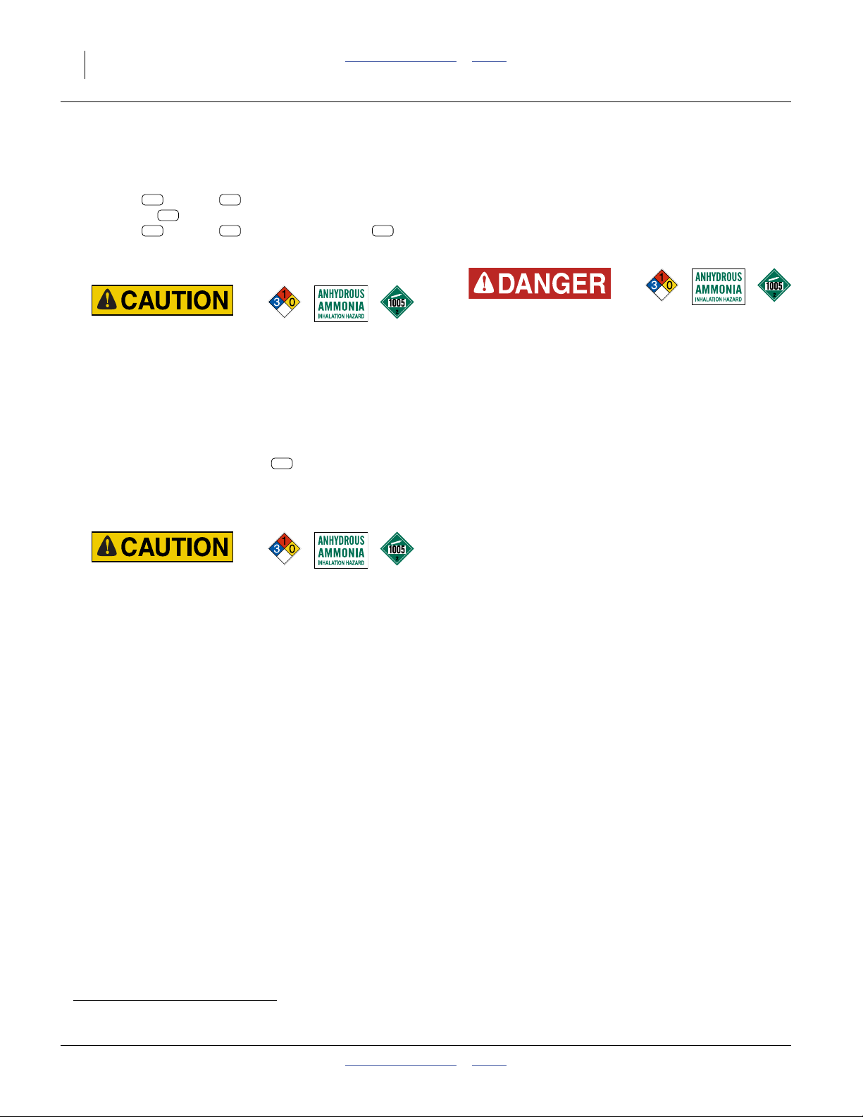
DANGER indicates an imminently hazardous situation
which, if not avoided, will result in death or serious injury.
This signal word is limited to the most extreme situations,
typically for machine components that, for functional
purposes, cannot be guarded.
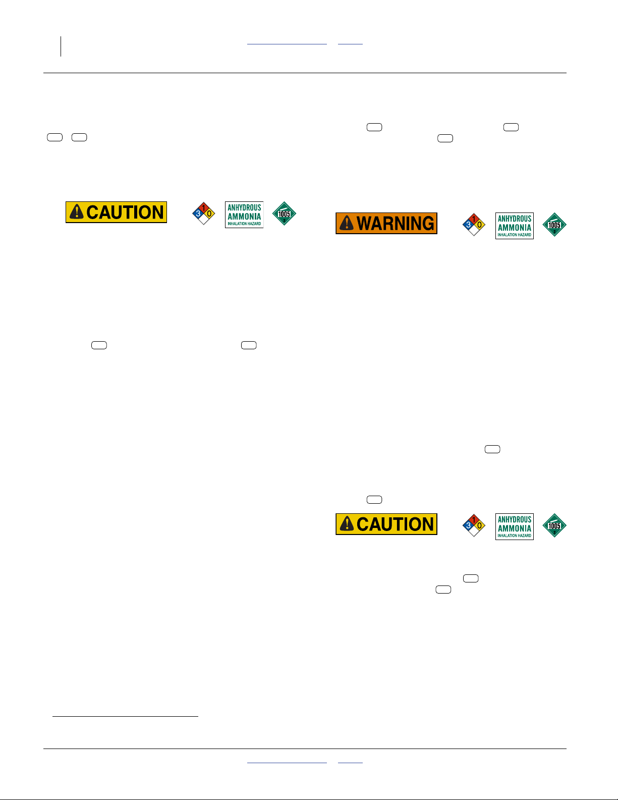
WARNING indicates a potentially hazardous situation
which, if not avoided, could result in death or serious
injury, and includes hazards that are exposed when
guards are removed. It may also be used to alert against
unsafe practices.
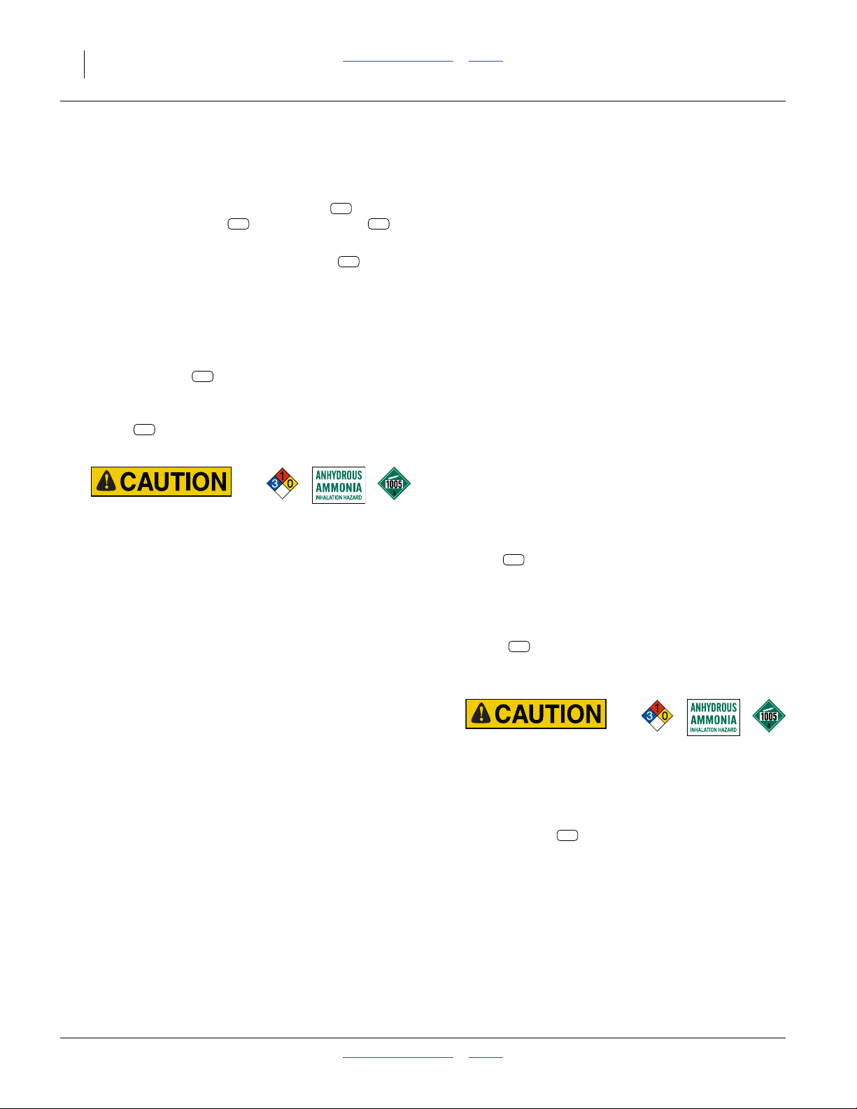
CAUTION indicates a potentially hazardous situation
which, if not avoided, may result in minor or moderate
injury. It may also be used to alert against unsafe
practices.
Prepare for Emergencies
▲ Be prepared if a fire starts.
▲ Keep a first aid kit and fire extinguisher handy.
▲ Keep emergency numbers for doctor, ambulance, hospital
and fire department near phone. Know the reporting
requirement for spills or releases of the chemicals you are
using. Have contact numbers available.
▲ For anhydrous ammonia operations, have additional
contact information for:
• national response center
• regional (state) response center
• local response center
▲ If a fire threatens an anhydrous ammonia tank, evacuate the
area. The tank may heat up faster than the relief valve can
vent the rising pressure, resulting in a catastrophic gas
release and possibly an explosion.
407-613M Table of Contents Index 2014-04-22

Great Plains Manufacturing, Inc. Table of Contents Index Important Safety Information 3
Be Familiar with Safety Decals
▲ Read and understand “Safety Decals”onpage9,
thoroughly.
▲ Read all instructions noted on the decals.
▲ Keep decals clean. Replace damaged, faded and illegible
decals.
Wear Protective Equipment (PPE)
▲ Wear clothing and equipment appropriate for the job. Avoid
loose-fitting clothing.
▲ Waterproof, wide-brimmed hat
▲ Face shield, goggles or full face respirator.
▲ Prolonged exposure to loud noise can cause hearing
impairment or loss. Wear suitable hearing protection such
as earmuffs or earplugs.
▲ Avoid wearing entertainment headphones while operating
machinery. Operating equipment safely requires the full
attention of the operator.
▲ See manual 407-551M for specific requirements and
recommendations for NH
▲ Goggles with side shields or a full face respirator are
required if handling or applying dusts, wettable powders, or
granules or if being exposed to spray mist.
▲ Cartridge-type respirator approved for pesticide vapors
unless conventional liquid fertilize label specifies another
type of respirator.
▲ Waterproof, unlined gloves. Neoprene is recommended.
▲ Cloth coveralls/outer clothing changed daily; waterproof
items if there is a chance of becoming wet with spray.
▲ Waterproof apron
▲ Waterproof boots or foot coverings
▲ Do not wear contaminated clothing. Wash protective
clothing and equipment with soap and water after each use.
Personal clothing must be laundered separately from
household articles.
▲ Clothing contaminated with certain pesticides must be
destroyed according to state and local regulations. Read
chemical label for specific instructions.
PPE.
3
2014-04-22 Table of Contents Index 407-613M
4 NP3000 and NP3000A Table of Contents Index Great Plains Manufacturing, Inc.
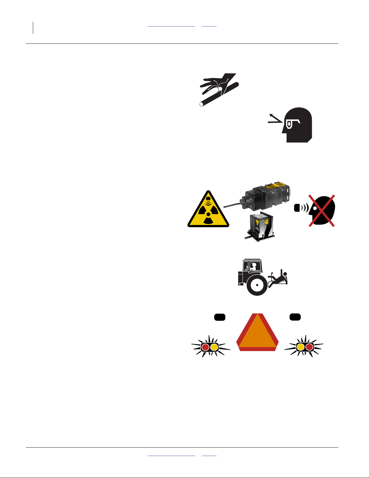
Avoid High Pressure Fluids
Escaping fluid under pressure can penetrate the skin,
causing serious injury. This fertilizer applicator requires a
Power-Beyond port, which is always under pressure
when the tractor is running.
▲ Avoid the hazard by relieving pressure before disconnecting
hydraulic lines.
▲ Use a piece of paper or cardboard, NOT BODY PARTS, to
check for suspected leaks.
▲ Wear protective gloves and safety glasses or goggles when
working with hydraulic systems.
▲ If an accident occurs, seek immediate medical attention
from a physician familiar with this type of injury.
Minimize Radiation Exposure
The optional DICKEY-john® RVS II and RVS III Radars
are intentional radiators of RF energy. Although its
radiated energy level is far below the limits set by
EN 61010-1:1993 A2:1995-Chapter 12.4, it is advisable
not to look directly into the face of the unit.
The radar must radiate toward the ground and at least
20 cm (8 inches) away from a human during use to
comply with the RF human exposure limits as called out
in FCC 47 CFR Sec.2.1091. DO NOT RE-MOUNT OR
USE THE RADAR IN A MANNER INCONSISTENT
WITH ITS DEFINED USE.
Keep Riders Off Machinery
Riders obstruct the operator’s view. Riders could be
struck by foreign objects or thrown from the machine.
▲ Never allow children to operate equipment.
▲ Keep all bystanders away from machine during operation.
Use Safety Lights and Devices
Slow-moving tractors and towed implements can create
a hazard when driven on public roads. They are difficult
to see, especially at night.
▲ Use flashing warning lights and turn signals whenever
driving on public roads.
▲ Use lights and devices provided with implement.
407-613M Table of Contents Index 2014-04-22
Great Plains Manufacturing, Inc. Table of Contents Index Important Safety Information 5
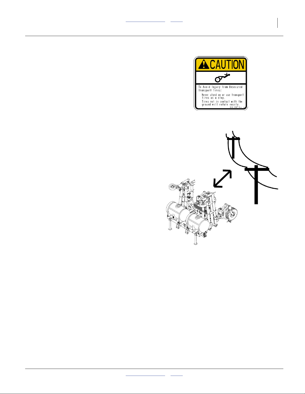
Tires Not a Step
Do not use gauge wheel or lift-assist tires as steps. A tire
could spin underfoot, resulting in a fall onto the applicator
or ground, possibly causing serious injury.
▲ The gauge wheel tires can be in poor ground contact at any
time, even with the fertilizer applicator lowered in the field.
They can appear to be in ground contact, and spin easily, in
multiple conditions.
▲ The lift-assist tires can be in poor ground contact, or out of
ground contact, whenever the fertilizer applicator is
lowered.
Remain Clear of Overhead Lines
▲ If the fertilizer applicator contacts a power line, lethal
voltage may be present on all metal parts. At higher voltage,
the applicator does not need to be in line contact for the
hazard to exist. Maintain at least 10 foot (3 m) clearance.
▲ Electrocution can occur without direct contact between the
energized fertilizer applicator and a person near the
fertilizer applicator.
▲ Watch for sagging, damaged or low electrical lines. The
folded fertilizer applicator could contact lines lower than
13 feet 2 inches (4 m). Overhead lines at farm structures
are a particular hazard.
▲ Watch for all electrical lines during folding and unfolding
operations. Use a spotter during folding and unfolding.
Know the location and height of all lines during transport
and in fields.
▲ If an electrical hazard is observed while on the ground near
the applicator, hop at least 100 feet (30 m) away with both
feet together and summon professional help. At higher
voltage, lethal voltage gradients can also be present at the
soil surface.
▲ Consult your tractor manual for advice on how to respond
to an electrical hazard event while in the cab.
2014-04-22 Table of Contents Index 407-613M
6 NP3000 and NP3000A Table of Contents Index Great Plains Manufacturing, Inc.
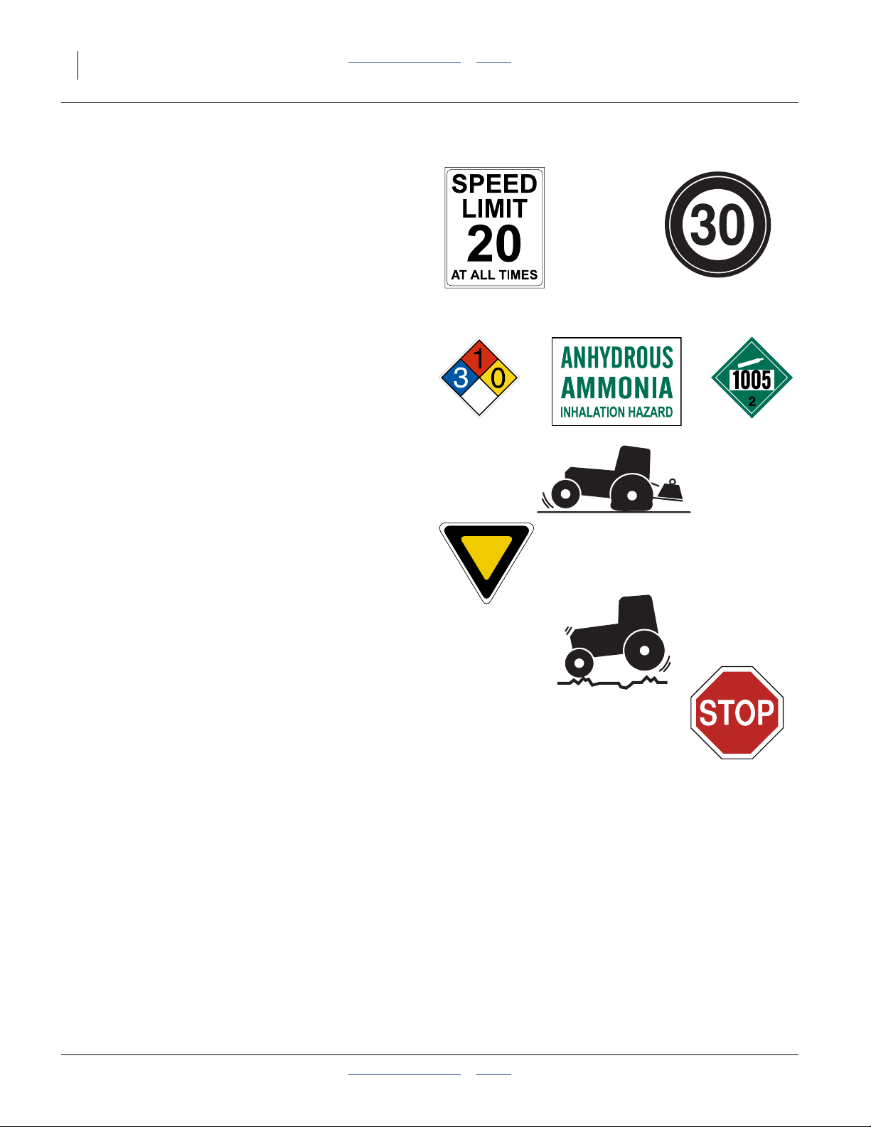
Transport Machinery Safely
Maximum transport speed for applicator is 20 mph (32
kph), 13 mph (22 kph) in turns. Some rough terrains
require a slower speed. Sudden braking can cause a
towed load to swerve and upset.
▲ Do not transport an applicator that weighs over 20,000
pounds (9060 kg). Loading liquid fertilizer tanks or
transporting with a nurse tank hitch to the applicator can
easily exceed this limit.
▲ Tow nurse tank separately. Do not tow a nurse tank in train
with the applicator on public roads.
▲ Never park an anhydrous ammonia tank on public roads or
anywhere near sites with high occupancy or high-risk
populations, such as shopping areas, events, schools,
hospitals, retirement communities, etc.
▲ Avoid transporting an anhydrous ammonia tank through
populated areas.
▲ Do not tow a lift-assisted 2-point applicator or nurse tank
that, when fully loaded, weighs more than 1.5 times the
weight of towing vehicle.
▲ Do not transport a 2-point applicator that exceeds the
capacity or ballasting of the tractor. There may not be
enough front wheel traction for safe steering.
▲ Carry reflectors or flags to mark fertilizer applicator in
case of breakdown on the road.
▲ Keep clear of overhead power lines and other obstructions
when transporting. Refer to transport dimensions under
“Specifications and Capacities” on page 142.
▲ Do not exceed 20 mph (32 km/h). Never travel at a speed
which does not allow adequate control of steering and
stopping. Reduce speed if towed load is not equipped with
brakes.
▲ Reduce speed on rough roads.
▲ Comply with national, regional and local laws.
▲ Do not fold or unfold the fertilizer applicator while the
tractor is moving (other than field lift).
407-613M Table of Contents Index 2014-04-22
Great Plains Manufacturing, Inc. Table of Contents Index Important Safety Information 7
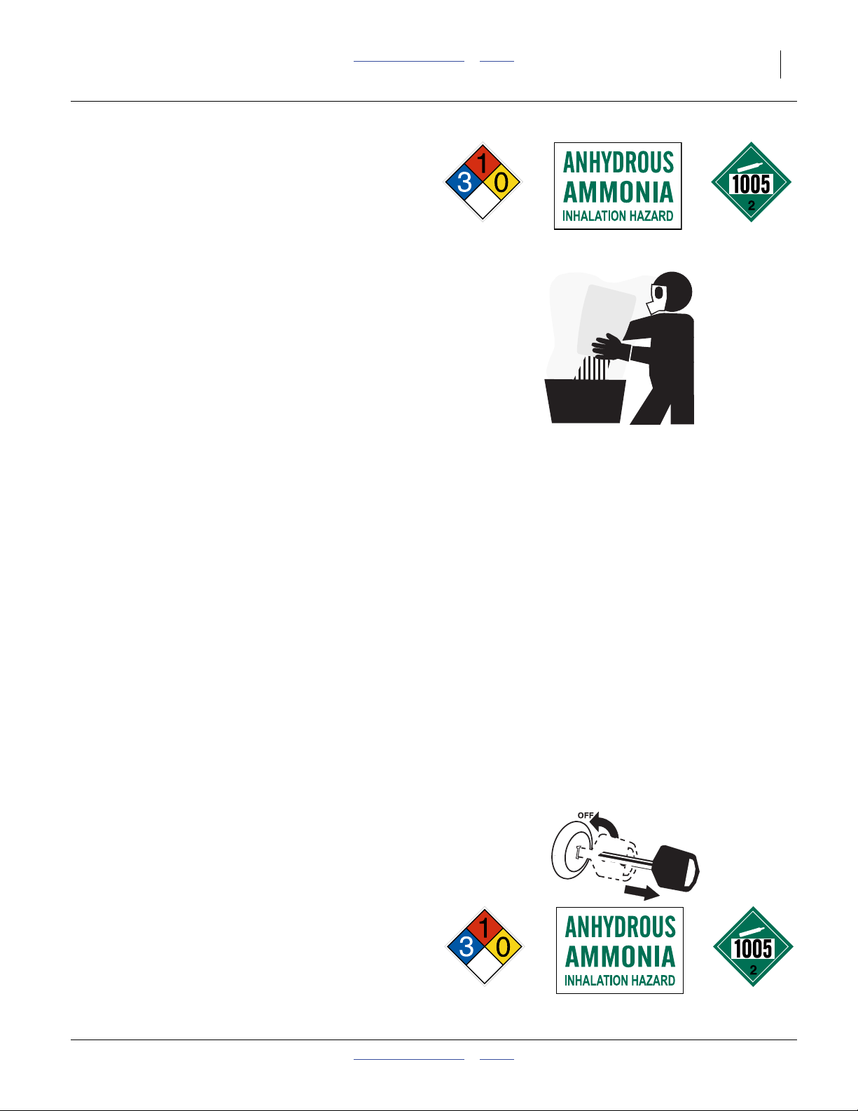
Handle Chemicals Properly
See manual 407-551M for specific requirements and
recommendations for NH
For Conventional Liquid Materials
Agricultural chemicals can be dangerous. Improper use
can seriously injure persons, animals, plants, soil and
property.
▲ Read and follow chemical supplier instructions.
▲ Wear protective clothing.
▲ Handle all chemicals with care.
▲ Agricultural chemicals can be dangerous. Improper use can
seriously injure persons, animals, plants, soil and property.
▲ Inhaling smoke from any type of chemical fire is a serious
health hazard.
▲ Store or dispose of unused chemicals as specified by the
chemical manufacturer.
▲ If chemical is swallowed, carefully follow the chemical
manufacturer’s recommendations and consult with a doctor.
▲ If persons are exposed to a chemical in a way that could
affect their health, consult a doctor immediately with the
chemical label or container in hand. Any delay could cause
serious illness or death.
▲ Dispose of empty chemical containers properly. By law
rinsing of the used chemical container must be repeated
three times. Puncture the container to prevent future use. An
alternative is to jet-rinse or pressure rinse the container.
▲ Wash hands and face before eating after working with
chemicals. Shower as soon as application is completed for
the day.
▲ Apply only with acceptable wind conditions. Wind speed
must be below 5 mph (8 km/h). Make sure wind drift of
chemicals will not affect any surrounding land, people or
animals.
▲ Never wash out a tank within 100 feet (30 m) of any
freshwater source or in a car wash.
.
3
Shutdown and Storage
▲ Lower fertilizer applicator, put tractor in park, turn off
engine, and remove the key.
▲ Secure fertilizer applicator using locks and supports
provided.
▲ Detach and store fertilizer applicator in an area where
children normally do not play.
▲ Park an anhydrous ammonia applicator downwind of
occupied areas until it is purged of NH3 residues.
▲ Do not leave NH3 nurse tanks unattended.
2014-04-22 Table of Contents Index 407-613M

8 NP3000 and NP3000A Table of Contents Index Great Plains Manufacturing, Inc.
Tire Safety
Tire changing can be dangerous and should be
performed by trained personnel using correct tools and
equipment.
▲ When inflating tires, use a clip-on chuck and extension hose
long enough for you to stand to one side–not in front of or
over tire assembly. Use a safety cage if available.
▲ When removing and installing wheels, use wheel-handling
equipment adequate for weight involved.
Practice Safe Maintenance
▲ Understand procedure before doing work. Use proper
tools and equipment. Refer to this manual.
▲ Work in a clean, dry area.
▲ Lower the fertilizer applicator, put tractor in park, turn off
engine, and remove key before performing maintenance. If
work must be performed with applicator raised, use blocks
or jackstands rated for the fertilizer applicator weight.
▲ Make sure all moving parts have stopped and all system
pressure is relieved.
▲ Allow applicator to cool completely.
▲ Disconnect battery ground cable (-) before servicing or
adjusting electrical systems.
▲ Welding: Disconnect battery ground. Avoid fumes from
heated paint.
▲ Inspect all parts. Make sure parts are in good condition
and installed properly.
▲ Remove buildup of grease, oil or debris.
▲ Remove all tools and unused parts from fertilizer
applicator before operation.
Safety At All Times
Thoroughly read and understand the instructions in this
manual before operation. Read all instructions noted on
the safety decals.
▲ Be familiar with all applicator functions.
▲ Operate machinery from the driver’s seat only.
▲ Do not leave applicator unattended with tractor engine
running.
▲ Do not stand between the moving tractor and applicator
during hitching.
▲ Keep hands, feet and clothing away from power-driven
parts.
▲ Wear snug-fitting clothing to avoid entanglement with
moving parts.
▲ Make sure all persons are clear of working area.
407-613M Table of Contents Index 2014-04-22
Great Plains Manufacturing, Inc. Table of Contents Index Important Safety Information 9
Safety Decals
Safety Reflectors and Decals
Your implement comes equipped with all lights, safety
reflectors and decals in place. They were designed to
help you safely operate your implement.
▲ Read and follow decal directions.
▲ Keep lights in operating condition.
▲ Keep all safety decals clean and legible.
▲ Replace all damaged or missing decals. Order new decals
from your Great Plains dealer. Refer to this section for
proper decal placement.
▲ When ordering new parts or components, also request
corresponding safety decals.
To install new decals:
1. Clean the area on which the decal is to be placed.
2. Peel backing from decal. Press firmly on surface,
being careful not to cause air bubbles under decal.
31960
818-055C
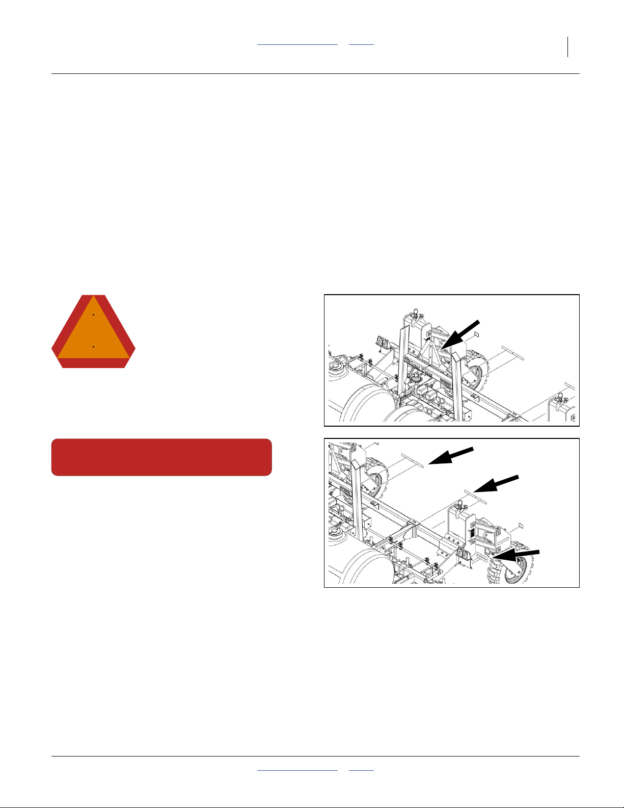
Slow Moving Vehicle Reflector
On a mount attached to the transport rest assembly;
1 total
838-266C
Red Reflectors
On the rear face light bracket, and
rear face of lift assist mount carrier tube;
4 total
31960
2014-04-22 Table of Contents Index 407-613M
10 NP3000 and NP3000A Table of Contents Index Great Plains Manufacturing, Inc.
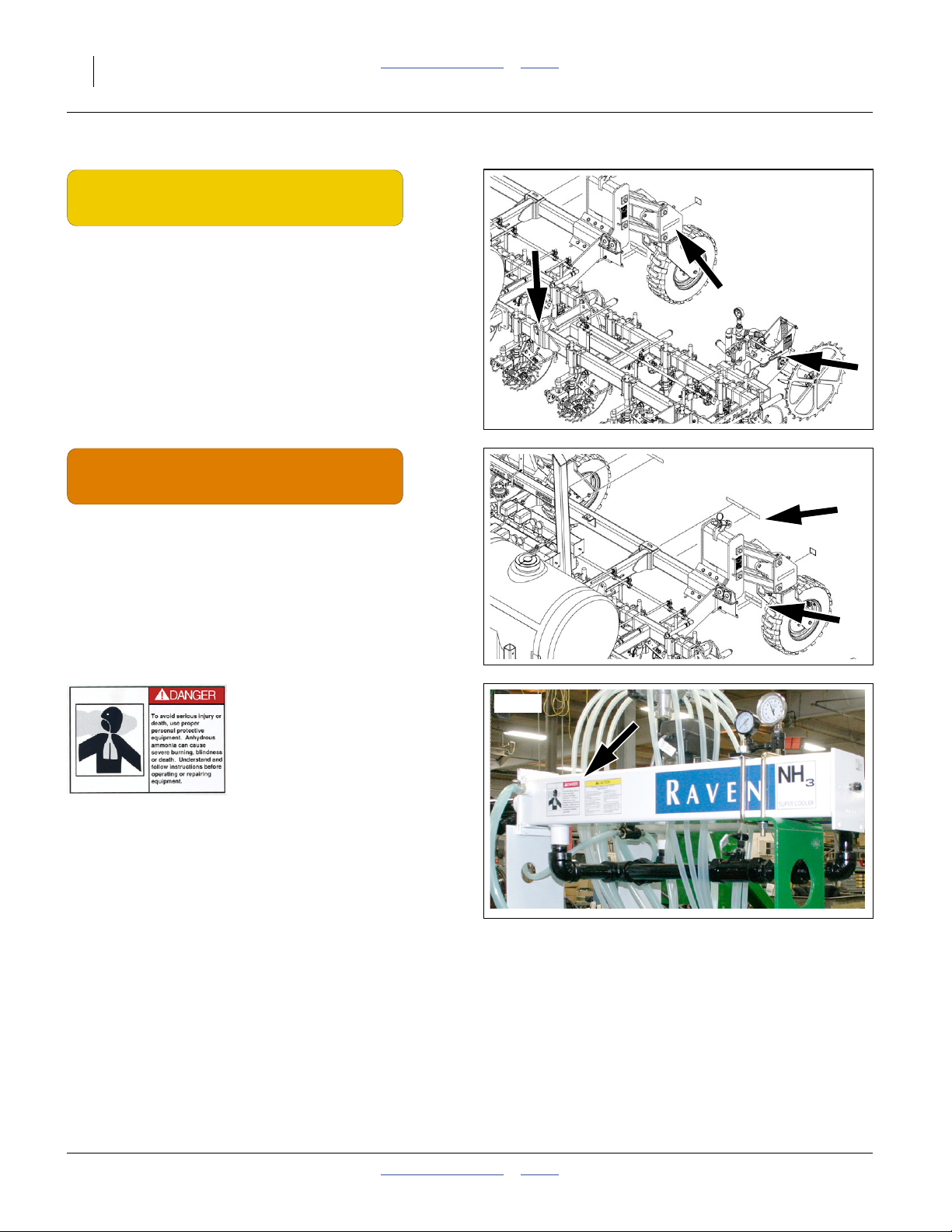
31960
838-265C
Amber Reflectors
On the outside faces of casters,
on the outside faces of lift assist braces,
Option: on the outside face of each ground drive pump;
4, 5 or 6 total
31960
838-267C
Daytime Reflectors
On the rear face of light bracket (below reds),
rear face of lift assist mount carrier tube (outboard of
reds);
4 total
Raven 039-0159-034 (Option) Danger: Ammonia
On front or back side of Raven AccuFlow™;
2 or 4 total
Order replacement from Raven Industries.
31603
407-613M Table of Contents Index 2014-04-22
Great Plains Manufacturing, Inc. Table of Contents Index Important Safety Information 11
31618
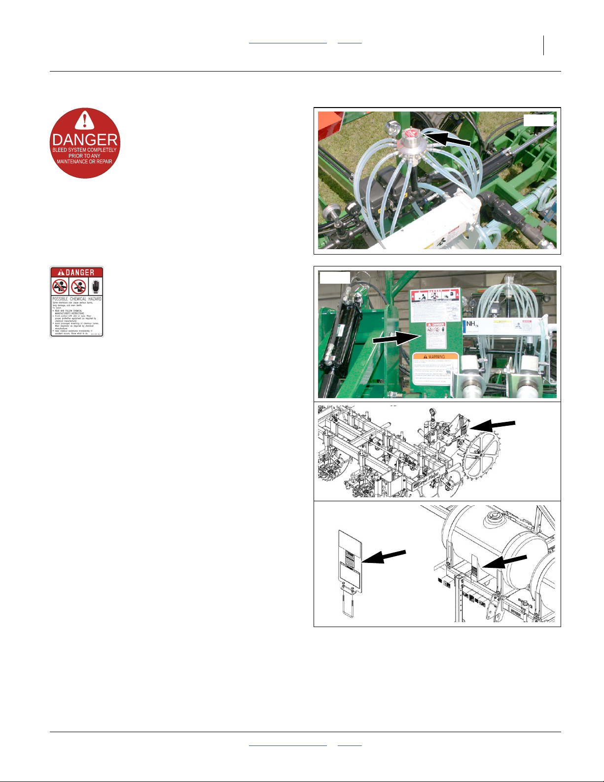
115527-01 (Option) Danger: Bleed System
On top of CDS-John Blue Impellicone® flow divider;
1 total
31604
818-323C Danger: Possible Chemical Hazard
NH3 models: On decal mount near Flo-Max™ coupler:
1 total
See “NH3 Operations” on page 55 and separate manual
“Using Anhydrous Ammonia Safely” (407-551M).
Conventional Models: On left face of ground drive pump
mount;
1 total
See “Liquid Operations” on page 68.
Conventional Models: On decal mount at optional rear
hitch and/or on front face of each center tank leg;
1 total
See “Liquid Operations” on page 68.
32339
31960
32339
2014-04-22 Table of Contents Index 407-613M
12 NP3000 and NP3000A Table of Contents Index Great Plains Manufacturing, Inc.
.eps
35.8%
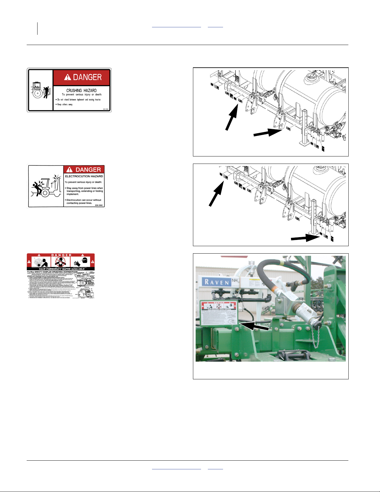
818-590C Danger: Hitch Crush
On front of frame tube, both sides of hitch;
2 total
31960
.eps
30.7%
838-599C Danger: Electrocution
On frame tube, outside parking stands;
2 total
848-534C (Squibb-Taylor FM125-2000) Danger: Safety Coupler (Option)
On decal mount near Flo-Max™ coupler;
1 total
This decal summarizes the mechanical procedure for
coupler re-connection after a breakaway event. Rely on
these instructions only if the Squibb-Taylor Flo-Max™
manual is not available. See “NH3: Breakaway Event”
on page 65.
31960
31529
407-613M Table of Contents Index 2014-04-22
Great Plains Manufacturing, Inc. Table of Contents Index Important Safety Information 13
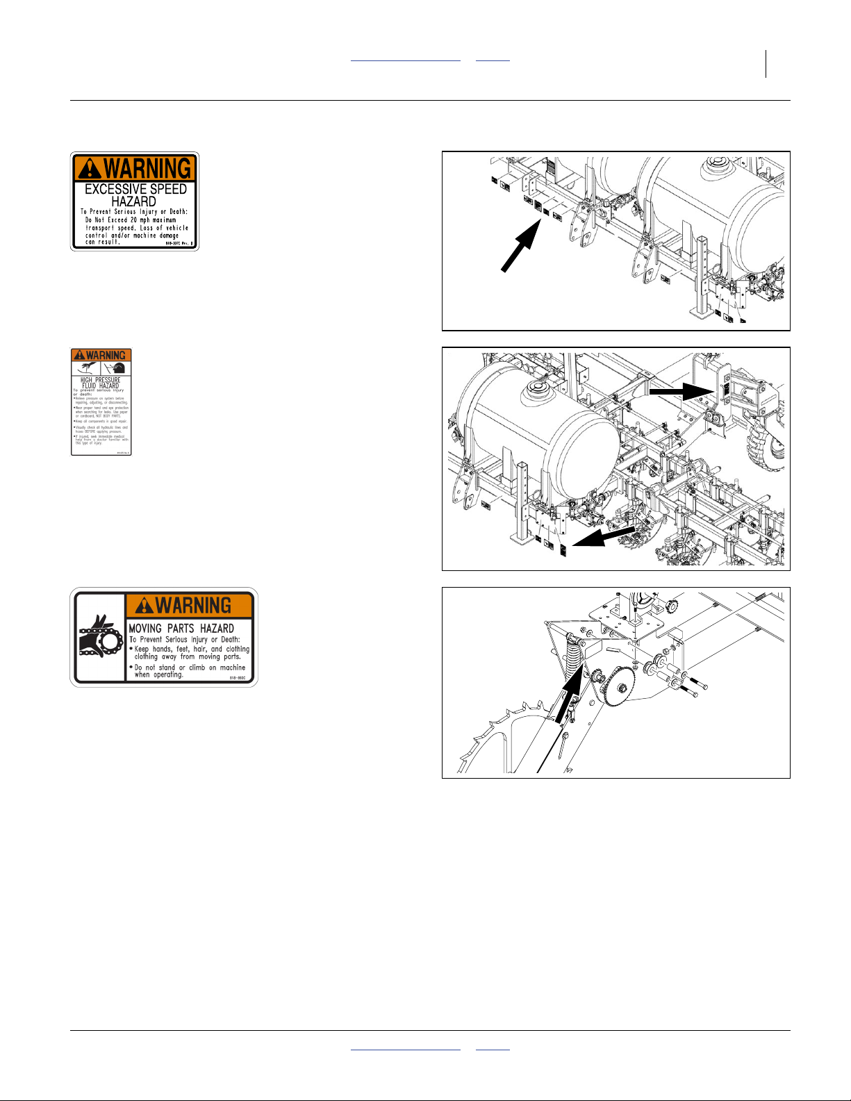
818-337C Warning: Speed
On front face of front tool bar, right of center;
1 total
31960
818-437C Warning: High Pressure Fluid Hazard
on front face of front tool bar, left end,
on each lift-assist mount;
3 total
818-860C (Option) Warning: Moving Parts
Option: on mount of each ground drive,
0, 1 or 2 total
31960
31085
2014-04-22 Table of Contents Index 407-613M
14 NP3000 and NP3000A Table of Contents Index Great Plains Manufacturing, Inc.
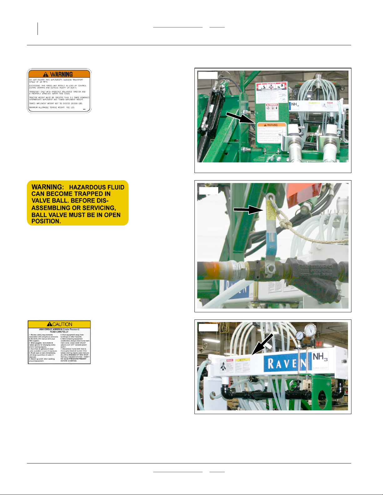
31604
848-551C Warning: Towing
On decal mount near Flo-Max™ coupler:
1 total
See “Transport” on page 53 and “Liq: Hitching
Conventional Nurse Tank” on page 70 for further
information.
31528
(no part number) Warning: Ball Valve (Option)
This decal should not apply to 2013+ NP3000A
applicators, but might be encountered on nurse tank
valves, or if repairs are made with old-stock after-market
parts. See “Avoid Ball Traps” on page 107.
Older unvented ball valves can trap fluid inside the ball if
closed with the line fully charged. Great Plains ball
valves shipped in 2011 and later have a bleed orifice on
the downstream side of the valve ball and do not require
this decal.
Raven 039-0159-035 Caution: Ammonia (Option)
On front or back side of Raven AccuFlow™;
2 or 4 total
Order replacement from Raven Industries.
31603
407-613M Table of Contents Index 2014-04-22
Great Plains Manufacturing, Inc. Table of Contents Index Important Safety Information 15
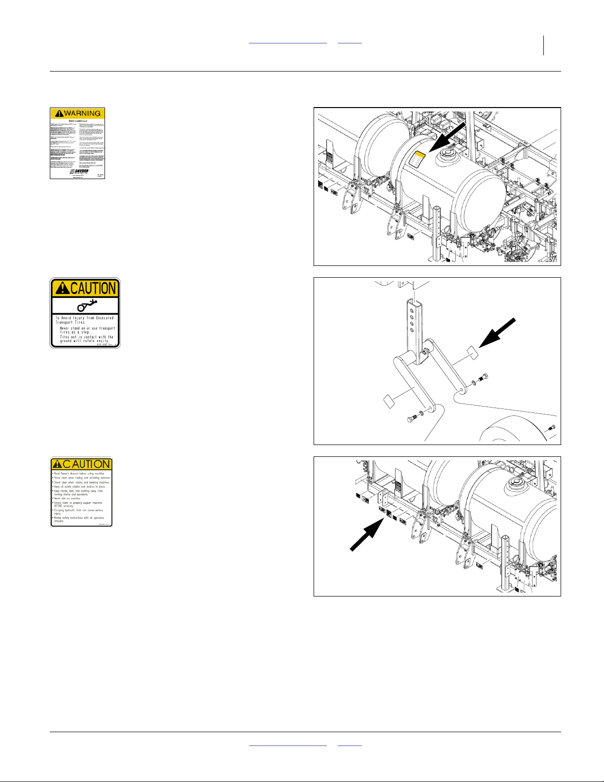
Snyder 997176 (Option) Warning: Tank Installation and Use
On upper front face of each tank:
0 or 2 total
Replacement decals available from Snyder Industries:
www.snydernet.com
31690
31921
818-398C Caution: Tires Not a Step
Outside faces of manual gauge wheel arms;
2 total
818-587C Caution: Read Operator’s Manual
On front face of front tool bar, right of center;
1 total
31960
2014-04-22 Table of Contents Index 407-613M
16 NP3000 and NP3000A Table of Contents Index Great Plains Manufacturing, Inc.
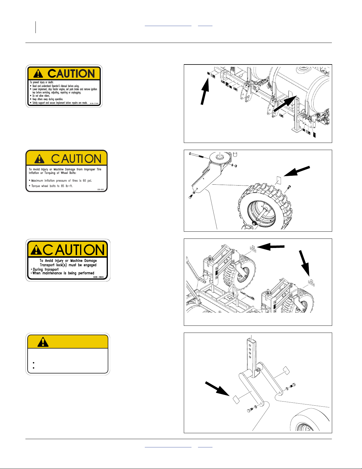
818-719C Caution: Read Operator’s Manual
On front face of front tool bar, right of center;
1 total
31960
838-092C Caution: Tire Pressure and Bolt Torque
Each lift-assist tire rim;
2 total
838-380C Caution: Transport Locks
On rear face of caster weldments, above red reflectors;
2 total
See “Important Safety Information” on page 1.
CAUTION
To Avoid Injur y or Machine Damage from Improper Tire
Inflation or Torquing of Wheel Bolts:
Maximum inflation pressure of tires is 90 psi.
Torque wheel bolts to 120 lb-ft.
838-595C
31045
32339
31921
838-595C Caution: Tire Pressure and Bolt Torque
Inside faces of manual gauge wheel arms;
2 total
407-613M Table of Contents Index 2014-04-22
Great Plains Manufacturing, Inc. Table of Contents Index Important Safety Information 17
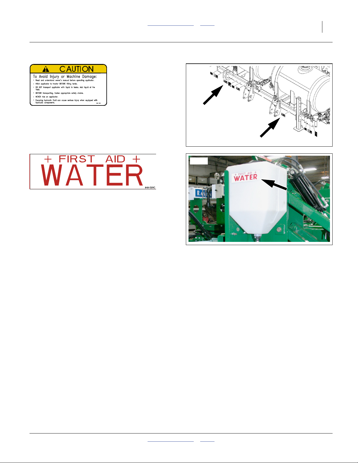
848-736C Caution: General
On front face of front tool bar, both sides;
2 total
31960
31599
848-539C General Safety: First Aid Water (Option)
On left and right sides of the wash water tank;
2 total
See “Ammonia Emergency Action” in the “Using
Anhydrous Ammonia Safely” manual (407-551M), and
“Wash Water” on page 46.
2014-04-22 Table of Contents Index 407-613M
18 NP3000 and NP3000A Table of Contents Index Great Plains Manufacturing, Inc.
Introduction
Great Plains welcomes you to its growing family of new
product owners. The 30-Foot Fertilizer Applicator
(NP3000 and NP3000A) has been designed with care
and built by skilled workers using quality materials.
Proper setup, maintenance, and safe operating practices
will help you get years of satisfactory use from the
machine.
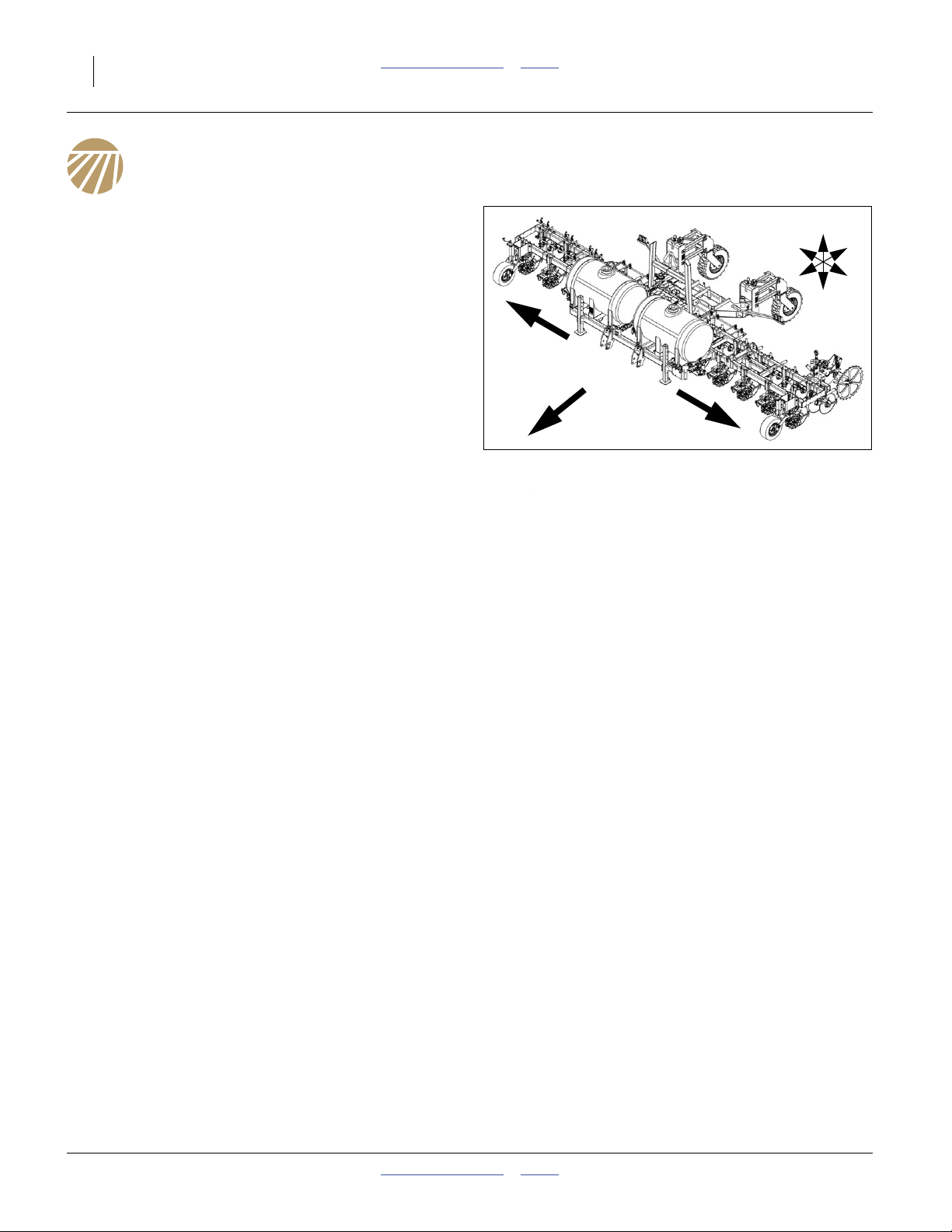
Description of Unit
The Nutri-Pro® is an applicator implement for
conventional liquid fertilizer, anhydrous ammonia (NH
or both. It has a working width (swath) of 30 feet (9.1 m).
The applicator has single or triple coulters with tines for
sub-soil application from optional on-board or
user-provisioned tanks.The NP3000/A has a lift-assisted
2-point hitch.
When configured for conventional liquid fertilizer, the
NP3000 model is designed for use with
an optional ground-drive CDS-John Blue® piston pump,
an optional variable-rate Ace hydraulic drive pump, or
a user-provisioned pump.
When configured for anhydrous ammonia the NP3000A
model relies on NH3 vapor pressure from a separately
provisioned trailing nurse tank.
A Raven SCS 450 console is available for sectional and
variable-rate control.
Models Covered
Conventional Liquid Fertilizer Models
NP3000-1230 30-Foot, 12-Row, 30 inch
NP3000-1230+SD 32.5-Foot, 13-Row, 30-inch
Anhydrous Model (configurable for two materials)
NP3000A-12C30 30-Foot, 12-Row, 30 inch
NP3000A-12C30+SD 32.5-Foot, 13-Row, 30-inch
Intended Usage
Use the NP3000/A Fertilizer Applicator to apply
compatible fertilizers. Do not modify Great
Plains-provisioned components, or install
user-provisioned components, except as authorized or
recommended by Great Plains.
)
3
U
R
F
D
R
L
Figure 1
NP3000/A Fertilizer Applicator
Document Family
407-613M NP3000/Aa Operator/Rate Manual
(this document)
407-613P NP3000 and NP3000A Parts manual
407-613Q NP3000/A Pre-Delivery manual
Manuals for Options:
407-551M Using Anhydrous Ammonia Safely
12-M-29 CDS-John Blue® IP-1300/1800
Impellicone® parts
016-0159-403 Raven AccuFlow™ Operator manual
016-0159-831 Raven SCS-450 Installation, Operation
and Service manual
FVC062 Squibb-Taylor Flo-Max™ manual
12-M-43 CDS-John Blue NGP Pump Parts and
Instructional manual
HYD-MAN
b
Ace Pump Instruction manual
a. For NP30A and NP40A, see manual 407-502M.
For NP30L and NP40L, see manual 407-313M.
For 2012- NP4000, see manual 407-776M.
For 2013+ NP4000/A, see manual 417-199M.
b. Available from Ace Pump Corporation:
http://www.acepumps.com
31959
B
L
407-613M Table of Contents Index 2014-04-22

Great Plains Manufacturing, Inc. Table of Contents Index Introduction 19
Using This Manual
This manual familiarizes you with safety, assembly,
operation, adjustments, troubleshooting, and
maintenance. Read this manual and follow the
recommendations to help ensure safe and efficient
operation.
The information in this manual is current at printing.
Some parts may change to assure top performance.
“Option” refers to components not part of the standard
product, and not “optional” steps. If the component is
installed, the instructions apply.
Identifies an Economic (not a Safety) Risk:
NOTICE provides a crucial point of information related to the
current topic. Read and follow the instructions to avoid damage
to equipment and ensure desired field results.
Note: This form sets off useful information about the
current topic, or forestalls possible
misunderstanding.
Right-hand and left-hand as used in
this manual are determined by facing
the direction the machine will travel
while in use unless otherwise stated.
An orientation rose in some line crt
illustrations shows the directions of:
Up, Back, Left, Down, Front, Right.
R
F
U
B
L
D
Single-digit and single-letter callouts refer to local
1
illustrations. The callout numbers/letters may be
re-used for different items on other pages.
Two-digit callouts in the range to and to
A00
L00
24 24
refer to the same tank and Nutri-Pro®plumbing
L51
system components throughout this manual. “A00”
references are for Anhydrous. “L00” references are
for conventional Liquid.
Callouts and above refer to parts of Options
(see Appendix C).
A11 A36 L11
2014-04-22 Table of Contents Index 407-613M
20 NP3000 and NP3000A Table of Contents Index Great Plains Manufacturing, Inc.
Owner Assistance
If you need customer service or repair parts, contact a
Great Plains dealer. They have trained personnel, repair
parts and equipment specially designed for Great Plains
products.
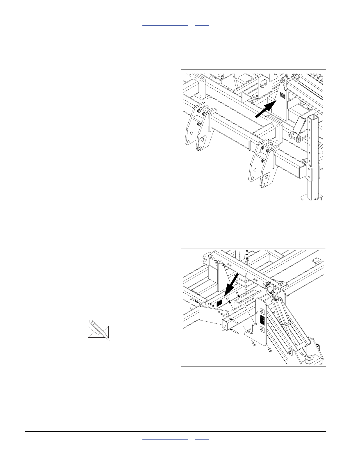
Refer to Figure 2 or Figure 3
Your machine’s parts were specially designed and
should only be replaced with Great Plains parts. Always
use the serial and model number when ordering parts
from your Great Plains dealer.
For 2013 and later applicators, the serial number plate is
located on the center section, on the front face of the left
front fold cylinder mount.
For 2012 and earlier applicators, the serial-number plate
is located on the rear face of the center frame, ahead of
the left caster pivot.
Record your fertilizer applicator model and serial number
here for quick reference:
Model Number:__________________________
Serial Number: __________________________
Your Great Plains dealer wants you to be satisfied with
your new machine. If you do not understand any part of
this manual or are not satisfied with the service received,
please take the following actions.
1. Discuss the matter with your dealership service
manager. Make sure they are aware of any problems
so they can assist you.
2. If you are still unsatisfied, seek out the owner or
general manager of the dealership.
For further assistance write to:
Figure 2
2013+ Serial Number Location
M # NP40A-25S20
36030
Product Support
Great Plains Mfg. Inc., Service Department
PO Box 5060
Salina, KS 67402-5060
gp_web_cs@greatplainsmfg.com
785-823-3276
Figure 3
2012- Serial Number Plate
407-613M Table of Contents Index 2014-04-22
31885
Great Plains Manufacturing, Inc. Table of Contents Index 21
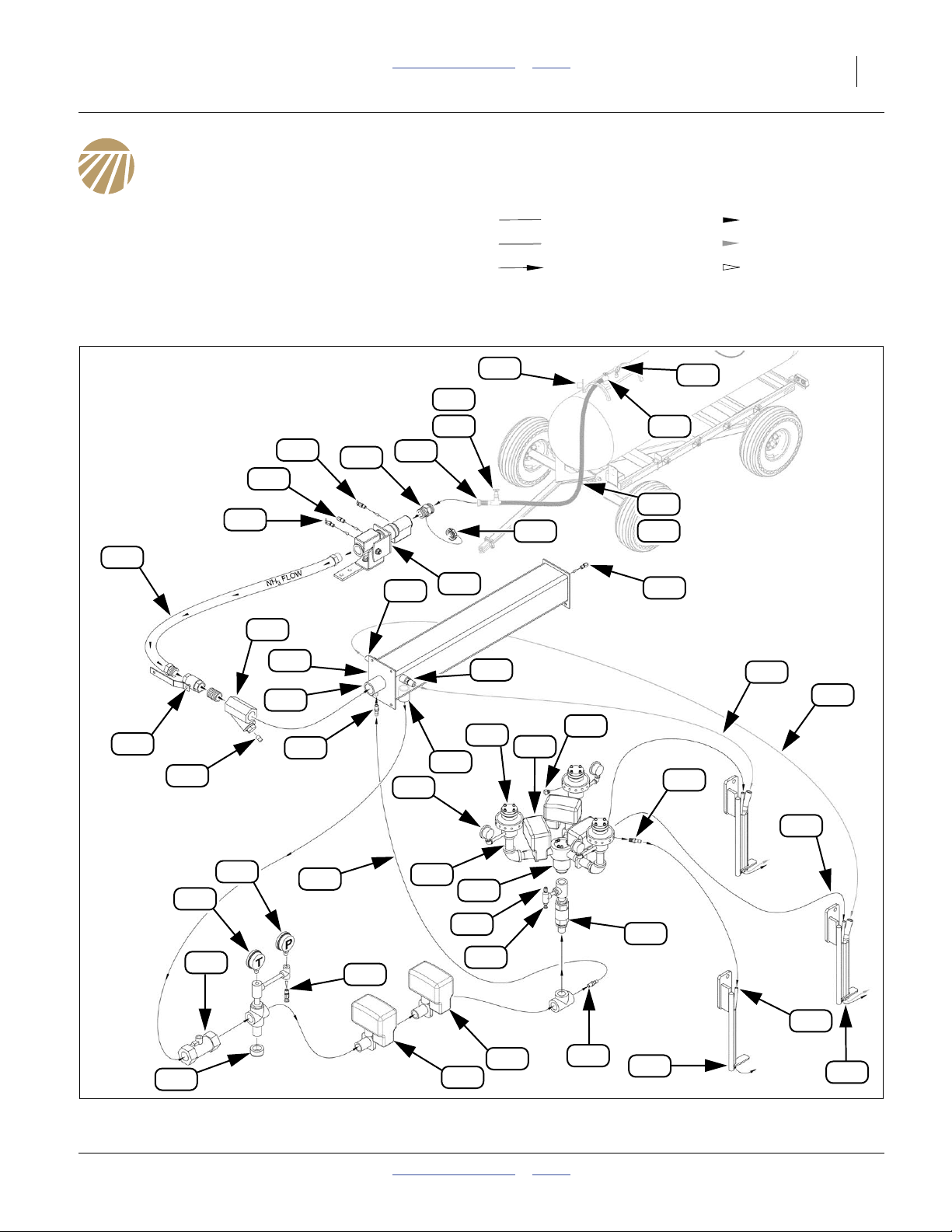
Application Overview
Legend:
Tank, plumbing and setup requirements differ for
anhydrous (A) and conventional systems (L). The next
few pages provide an overview of both systems.
Anhydrous: System Components
Single-Cooler Section Control Configuration - see
page 146 through page 150 for alternates.
Callout numbers A11 through A36 identify the same
applicator and tank components throughout this manual.
Liquid NH
NH3 Vapor Vapor Flow
Direction of Flow Exception Flow
3
Liquid Flow
A17
A18
A20
A15
A16
A19
A13
A21
A22
A34
A12
A7
A47
A42
A10
A11
A14
A24
A6
A47
A40
A11
A39
A17
A15
A8
A9
A23
A48
A48
A44
A43
A45
A27
A25
A28
A33
A29
A41
A38
A37
A36
A35
A45
A31
A26
Anhydrous Ammonia (NH3) Plumbing (Single-Cooler w/ Section Control)
2014-04-22 Table of Contents Index 407-613M
A30
Figure 4
A32
A46
A49
34958
22 NP3000 and NP3000A Table of Contents Index Great Plains Manufacturing, Inc.
NH3 System Narrative
This list describes a single-cooler anhydrous system with
section control. A dual-cooler system has two of
components through , and two additional
dual-tube tines . A single-section system lacks
components through and has only one of .
Refer to Figure 6 on page 29
A11.Acme cap
Suffocation, Blinding and Burning Hazards:
See “NH3: Safing Applicator Before Cart Hitch” on
page 55, for safe opening procedure.
This captive cap protects the inlet when no nurse
tank is connected. NH3might be sealed behind this
cap.
A12.Acme inlet
The nurse tank hose coupler connects here and
must have 13⁄4-4 female Acmea swivel coupler. See
page 58 for nurse tank connection.
A13.Coupler Inlet Bleed Valve
Suffocation, Blinding and Burning Hazards:
See “About Bleed Valves:” on page 38.
This fitting is carefully opened at normal and
abnormal disconnects, to bleed NH3 liquid and
vapor from the hoses (or to bleed just the nurse tank
hose upon breakaway). It is also opened prior to
Acme cap removal to verify that the line is
discharged. See “NH3: Making Nurse Tank
Connections” on page 58, “NH3: Unhitching
Nurse Tank” on page 67 and “NH3: Breakaway
Event” on page 65.
A11 A24
A49
A35 A39 A40
A7
A14.Breakaway Coupler
Upon Event: Probable Chemical Hazard:
See “NH3: Breakaway Event” on page 65.
This assembly is designed to separate and seal the
lines if between 300 to 400 pounds of pull force is
applied to the nurse tank hose. In normal
operations, this does not happen.
Should the hitch fail, and both safety chains fail, or
an operator makes serious basic safety errors, the
breakaway separates to protect the hoses from
rupture. Spring-loaded checks inside the breakaway
seal both ends of the now-broken connection. If the
line was charged, 60 cc of liquid NH3is released on
breakaway.
Resetting a parted breakaway coupler is a complex
operation requiring tools. Consult the breakaway
manual for details. More significant matters are
safing the applicator and nurse tank, then correcting
the cause of the breakaway. See “NH3: Breakaway
Event” on page 65.
A15.Breakaway Hydrostatic Relief Valve
In normal operation, this valve does not activate.
It is designed to open at 375 psi, well above the
250-265 psi operating pressure of the nurse tank’s
main pressure relief valve.
Operator action is periodic inspection, and to
replace this hydrostatic relief valve, a time-dated
part, when it reaches the end of its operating life
(see page 114). See “Hydrostatic Relief Valve
Maintenance” on page 112 for maintenance.
Valve function: when operating valves are closed on
both sides of the breakaway (or on just the
applicator side upon a breakaway event), NH3 can
be trapped in the breakaway coupler. As the NH
warms, it could create dangerously high pressure.
This relief valve opens to vent excess pressure.
3
a. Acme refers to the ANSI/ASME B1.5-1997 screw thread, which has a trapezoidal thread profile.
407-613M Table of Contents Index 2014-04-22

Great Plains Manufacturing, Inc. Table of Contents Index Application Overview 23
A16.Coupler Outlet Bleed Valve
Suffocation, Blinding and Burning Hazards:
See “About Bleed Valves:” on page 38.
This fitting is kept closed in normal operations.
When the breakaway is properly coupled, the inlet
bleed valve bleeds the entire assembly, and
A13
applicator supply hose. On breakaway, this valve is
used to bleed the applicator side of the
disconnection. See “NH3: Breakaway Event” on
page 65.
A17.Supply Hose
This connects the breakaway coupler to the
emergency shut-off valve. Operator action is to
replace this hose, a time-dated part, when it
reaches the end of its operating life (see page 114).
A18.Emergency Shut-off Valve
The handle of this is valve has a rope which is
routed to the tractor cab (see page 38). Closing this
valve stops NH3flow to the cooler, metering system
and tines. There can still be a substantial amount of
NH3 in the system, for some time, with this valve
closed. See the “Using Anhydrous Ammonia
Safely” manual (407-551M) for emergency
operation.
A19.Strainer
This filter contains a 20 mesh screen and two
ceramic magnets to remove debris from the NH
flow.
A20.Strainer Magnets
These capture ferrous metal debris of any size.
They need to be cleaned every 4 to 5 tank loads.
See page 117.
A21.AccuFlow™ Super Cooler (Heat Exchanger)
For effective application, NH3needs to remain in the
liquid state until released underground. This is
accomplished by refrigeration. Some of the flow is
tapped , fed back to the cooler at , vaporized
and used to chill the fluid passing from to .
A32 A34
A22 A24
A22.Cooler Intake
Liquid NH
enters the cooler here.
3
A23.Cooler Hydrostatic Relief Valve
In normal operation, this valve never activates. NH
3
can get trapped in the system between the
emergency shut-off valve and the On/Off
valve , if both valves are closed while the system
A31
A18
is charged. As the liquid warms and pressure rises,
this valve protects the system with periodic
releases.
This valve is set to activate at 350 psi, higher than
the nurse tank’s relief valve.
Operator action is periodic inspection, and to
replace this hydrostatic relief valve, a time-dated
part, when it reaches the end of its operating life
(see page 115). See “Hydrostatic Relief Valve
Maintenance” on page 112 for maintenance.
A24.Cooler Outlet
Chilled liquid NH3 exits the cooler here.
A25.Flow Meter
This fitting converts fluid flow to pulses for the
SCS 450 controller. It has a range of 1-60 gpm. A
tag on the cable lead provides a “METER CAL”
number specific to the installed meter (and accurate
only for NH3 fluid flow, and not NH3 vapor flow).
A26.Drain Cap
The plumbing cross and lower cap below the
temperature gauge are provided to allow the gauge
3
probe to be exposed to the full NH3 stream. This
cap does not require periodic clean-out.
A27.Temperature Gauge
This gauge reports the temperature of the chilled,
flowing, NH3. When NH3 is not flowing, this gauge
slowly drifts up to ambient temperature.
Checking the temperature and pressure gauges
A28
against the chart in the “Using Anhydrous
Ammonia Safely” manual (407-551M), or in the
Raven AccuFlow™ manual, indicates whether the
flowing NH3 is in a liquid state.
Normal field temperatures of the chilled flowing NH
3
are in the range 20 to 83°F (-7 to 28°C).
2014-04-22 Table of Contents Index 407-613M
24 NP3000 and NP3000A Table of Contents Index Great Plains Manufacturing, Inc.
A28.Pressure Gauge
This gauge reports the pressure of the NH
exits the cooler. If line valves are closed, a pressure
reading above zero indicates NH
between the emergency shut-off valve and the
On/Off solenoid valve (the Control Valve
A31 A30
is present
3
A18
does not completely close).
Checking the pressure and temperature against
the chart in the “Using Anhydrous Ammonia
Safely” manual (407-551M), or in the Raven
AccuFlow™ manual, indicates whether the flowing
NH3 is in a liquid state.
When valves are open but NH3 is not flowing, this
gauge normally reads within 5 psi of the nurse tank
pressure gauge . If they are materially different
A17
at zero flow, one of the gauges may be defective.
When NH3 is flowing, the pressure reported by this
gauge is lower than the tank pressure.
A28
A29.Cooler Bleed Valve
Suffocation, Blinding and Burning Hazards:
See “About Bleed Valves:” on page 38.
This valve is normally closed. It is used to bleed
trapped NH3 from the cooler system when valves
are closed. It can also be used to accelerate
clearing the cooler system for maintenance.
A30.Control Valve
This is a variable electronic valve controlled by the
SCS 450. It is the primary control point for
application rate. When power is off, this valve
remains at its most recent setting.
This valve has a visible indicator above the valve
ball casing, indicating whether open, closed or in
between.
When commanded to a rate of zero, this valve does
not completely close. Use shut-off valves to
completely stop flow. A full slew from fully open to
minimum takes approximately 9 seconds.
A27
after it
3
A31.Master Shut-Off Valve
This is the normal control for starting and stopping
total application flow in the field (for turns, etc.). This
component is an open/close solenoid valve
controlled by the “MASTER” switch on the SCS 450.
When power is off, this valve remains at its most
recent setting.
This valve has a visible indicator above the valve
ball casing, indicating whether open or closed.
Operation of this valve is essentially instantaneous.
Its valve ball is equipped with a downstream relief
orifice.
A32.Refrigerant Tap
A small amount of the NH3flow is taken at this point
to provide refrigeration at the cooler. There are no
operational items for this fitting.
A33.Refrigerant Line
This tubing passes tapped refrigerant NH3 to the
cooler. Operator action is to replace this tubing,
a time-dated part, when it reaches the end of its
operating life. See page 115.
A34.Cooler Refrigerant Inlet
Tapped refrigeration flow enters the cooler at this
fitting, and is vaporized to chill the liquid entering at
fitting . There are no operational items for this
A22
fitting.
A35.Section Control Check Valve
(Section Control Option Only)
This prevents back flow when section shut-off
valves are off with NH3 present. There are no
A39
operational items for this fitting.
A36.Section Control Bleed Valve
Suffocation, Blinding and Burning Hazards:
See “About Bleed Valves:” on page 38.
(Section Control Option Only)
This valve is normally closed. It is used to bleed
trapped NH3 from the section control system if all
section valves are closed.
A39
407-613M Table of Contents Index 2014-04-22

Great Plains Manufacturing, Inc. Table of Contents Index Application Overview 25
A37.Section Control Relief Valve
(Section Control Option Only)
In normal operation, this valve never activates.
NH3can get trapped in the system between the
section control check valve and the section
shut-off valves , if all section valves are closed
A39
A35
while the system is charged. As the liquid warms
and pressure rises, this relief valve protects the
system with periodic releases.
This valve is set to activate at 350 psi.
Operator action is periodic inspection, and to
replace this hydrostatic relief valve, a time-dated
part, when it reaches the end of its operating life
(see page 115). See “Hydrostatic Relief Valve
Maintenance” on page 112 for maintenance.
A38.Section Flow Divider
(Section Control Option Only)
This is a CDS-John Blue®Impellicone® manifold.
It evenly splits the NH3 flow for distribution through
the row flow dividers . There are no operational
A40
items for this component.
A39.Section Shut-Off Valves
(Section Control Option Only)
These are the normal controls for suspending
per-section application flow in the field (for point
rows, pass overlap, etc.). These are open/close
solenoid valves controlled by the “BOOMS”
switches on the SCS 450.
When used with the SCS 450 or other suitable
sectional application controller, shutting off a
section causes the total flow to be reduced by1⁄3 of
the all-sections-on rate, keeping the rate constant
for the section(s) still active.
Each section valve has a visible indicator above the
valve ball casing, indicating whether open or closed.
Operation of each section valve is essentially
instantaneous. However, there is considerable
residual NH3in the section flow divider and delivery
tubes after shut-off. When console power is off, the
valves remain at their most recent setting.
The valve balls are equipped with a downstream
relief orifice.
A40.Row Flow Divider(s)
This is a CDS-John Blue®Impellicone® manifold. It
evenly splits the NH3flow for distribution through the
delivery tubes . There are no operational items
A45
for this component.
A41.Flow Divider Manifold Inlet
NH3 liquid flow enters the flow divider here.
A42.Flow Divider Pressure Gauge
This gauge reports the pressure prior to flow
division. It normally reads lower than the cooler and
nurse tank pressure gauges.
A43.Flow Divider Outlet
Each of these ports receives an equal fraction of the
NH3 liquid flow.
A44.Flow Divider Plug
Unused ports are plugged with a steel NPT plug.
Unused ports do not affect flow balance at the other
ports.
A45.Delivery Tube
This tubing passes NH3 liquid flow to the tines.
Operator action is to replace this tubing, a
time-dated part, when it reaches the end of its
operating life. See page 116.
A46.Coulter Tine (Single)
Tines inject the liquid NH3. All but two (or four) of the
rows are equipped with tines having a single smaller
liquid delivery tube. Tines need frequent inspection
for wear and damage.
A47.Cooler Vapor Outlets (2)
Two vapor outlets direct the now-gaseous
refrigerant flow (that entered at ) to two special
tines per cooler.
A49
A34
A48.Vapor Tube
This tubing passes NH3vapor flow to the dual tines.
Operator action is to replace this tubing,
a time-dated part, when it reaches the end of its
operating life. See page 116.
A49.Coulter Tine (Dual)
There are two of these special tines per cooler (four
total on a dual-cooler applicator). They direct the
vaporized refrigerant NH3 gas into the soil at the
larger rear vapor tube. They are otherwise identical
to the single-tube tines .
A46
2014-04-22 Table of Contents Index 407-613M
26 NP3000 and NP3000A Table of Contents Index Great Plains Manufacturing, Inc.
The following callouts are for trailing nurse tank cart
components. See the “Using Anhydrous Ammonia
Safely” manual (407-551M) for all nurse tank callouts
( - ). The present manual lists only those required
A1
A36
for applicator field operations.
A6.Acme Parking Plug
A threaded stud (or other means) for storage of the
outlet hose when not coupled to the applicator.
Excess NH3 Release Hazard:
If the outlet hose is entirely dismounted (both ends free)
for transport and storage, and both ends are 13⁄4-4 Acme,
be sure about which end is which. Installing a hose
backwards can result in needless excess NH3 release at
unhitching, or a line segment unprotected by bleed and/
or relief valves.
A7.Acme Female Hose Coupler
This end of the hose connects the tank withdrawal
valve to the leading applicator inlet at the
A13 A12
breakaway coupler. For use with a Nutri-Pro
®
applicator, the outlet end of the hose must be
equipped with a 13⁄4-4 female Acme fitting.
The outlet end of the hose has a swivel collara or
shroud containing the female Acme fitting. This
allows connection without needing to twist the hose.
Acme hose couplers are intended for hand
tightening only. Do not use tools to make the
cart-applicator connection. A liquid-tight seal is
made by the gasket in the male Acme fitting on the
applicator break-away coupler.
For dual-tank carts, each tank usually has its own
hose.
A8.Outlet Hose Assembly
The hose may have zero, one or two operating
valves , one or more bleed valves , and a
hydrostatic relief valve . The outlet end may
A10 A11
A12
have an Acme. plug.
Hose valves are typically hand wheel valves, or
lever valves. Read any documents provided for the
valves. Have the terminal or dealer explain how the
valves work.
Suffocation, Blinding and Burning Hazards:
Never test an anhydrous ammonia hose valve unless you
are absolutely certain the hose and valve bodies are
empty, or both hose ends are securely connected to
sealed systems.
▲ A two-valve hose can contain a substantial amount of
NH
even when completely disconnected. See “Avoid
3
Line Traps” on page 106.
▲ Older ball valves can contain NH3 inside the ball
when closed, even though disconnected at both ends.
See “Avoid Ball Traps” on page 107.
Follow instructions for bleeding and checking. Never use
a valve handle as a carrying handle. Keep hands clear of
bleed valves when carrying a hose.
A9.Nurse Tank Hose Body
NH3 hoses are time-dated components. Operator
action is to replace the assembly when it
A8
reaches the end of its operating life.
A10.Hose Valve(s)
The hose may have zero, one or two operating
valves .
A10
Excess NH3 Release and Trapping Hazards:
Understand hose and tank withdrawal valve functions
and sequencing. This manual presumes a hose with a
single outlet-end shut-off valve , and a tank outlet
with a withdrawal valve . If the hose in use is
A10
A15
different, have the hose provider explain the correct
order for operations.
a. Acme collars may be aluminum, but all internal coupler components must be NH3-safe, typically stainless steel.
407-613M Table of Contents Index 2014-04-22
 Loading...