

Page 1

Great Plains Manufacturing, Inc. General Information 1
Min-Till Ladder Kit
Installation Instructions for use with
Two- and Three-Section Folding Drills
Applies to Models:
• 2S-2600/2610/F/HD/HDF
• 3S-3000/F/HD/HDF
• 3S-4000/F/DH/HDF
When you see this symbol, the subsequent instructions
!
and warnings are serious - follow without exception.
Your life and the lives of others depend on it!
General Information
These instructions explain how to install the Min-Till Ladder Kit. This kit replaces the single fixed walkboard steps
with 3-step swing-down ladders.
Each kit converts an entire drill.
These instructions apply to:
Kit Kit Description
195-065A Min-Till Ladder Kit
This kit contains all components necessary for installation.
If installing this kit as part of Pre-Delivery, install the
walkboards (without any fixed steps) prior to installing
the ladders.
Before You Start
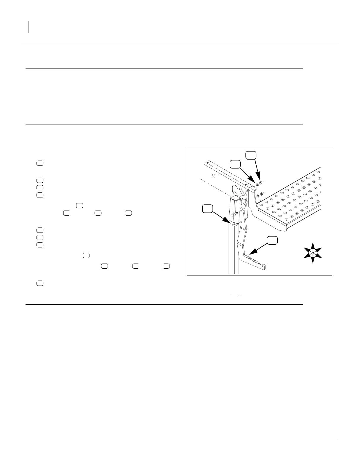
Refer to Figure 1
Review these instructions, and make sure you understand where and how the ladders install, and which existing parts are removed.
!
WARNING
If unfolded, the drill must be hitched to a tractor during
Opener Lift, to avoid negative tongue weight. Hitch loads can
range between +4000 pounds (folded) and -1000 pounds
(unfolded), depending on drill model and configuration.
Tools Required
• basic hand tools
• if unfolding is desired, a tractor with two hydraulic circuits and suitable hitch
These instructions presume an existing drill with fixed
steps. The installation may be done with the drill folded
or unfolded.
Figure 1
Ladder Installed
Notations and Conventions
“Left” and “Right” are facing in the
direction of machine travel. An orientation rose in the line art illustrations
shows the directions of Left, Right,
Front, Back, Up, Down.
1
11 26
to
51 55
to
callouts identify components in the currently
referenced Figure or Figures.
callouts reference new parts from the list on
page 6. The descriptions match those on the
cartons, bags or item tags, as well as your
updated Parts Manual.
callouts reference affected existing parts
from the table on page 7. The descriptions
match those in your Parts Manual.
U
F
L
R
B
D
27033
U
F
L
R
B
D
09/10/2007 195-066M
Page 2
2 Ladder Kit Great Plains Manufacturing, Inc.
Pre-Assembly Preparation
1. Inventory the contents per “New Parts: Kit 195065A” on page 6.
2. If the drill is unfolded, lower the parking stands, lower
the openers, and lower the drill.
Remove Fixed Steps
Begin with the left step.
Refer to Figure 2
3. Loosen both nuts
54
NUT HEX 1/2-13 PLT.
4. On the lower bolt only, remove and save:
54
NUT HEX 1/2-13 PLT
55
WASHER LOCK SPRING 1/2 PLT
53
HHCS 1/2-13X1 3/4 GR5
54
55
5. Swing the step backward, and re-install the saved
lower bolt , washer and nut .
6. Remove and save the upper:
54
NUT HEX 1/2-13 PLT
55
WASHER LOCK SPRING 1/2 PLT
53
HHCS 1/2-13X1 3/4 GR5
7. Remove the step . It is not re-used.
8. Re-install the saved bolt , washer and nut
9. Repeat step 3 through step 8 for the right hand step
52
(shown in Figure 8 on page 7).
51
53 55 54
51
53 55 54
Install Ladder Mounts
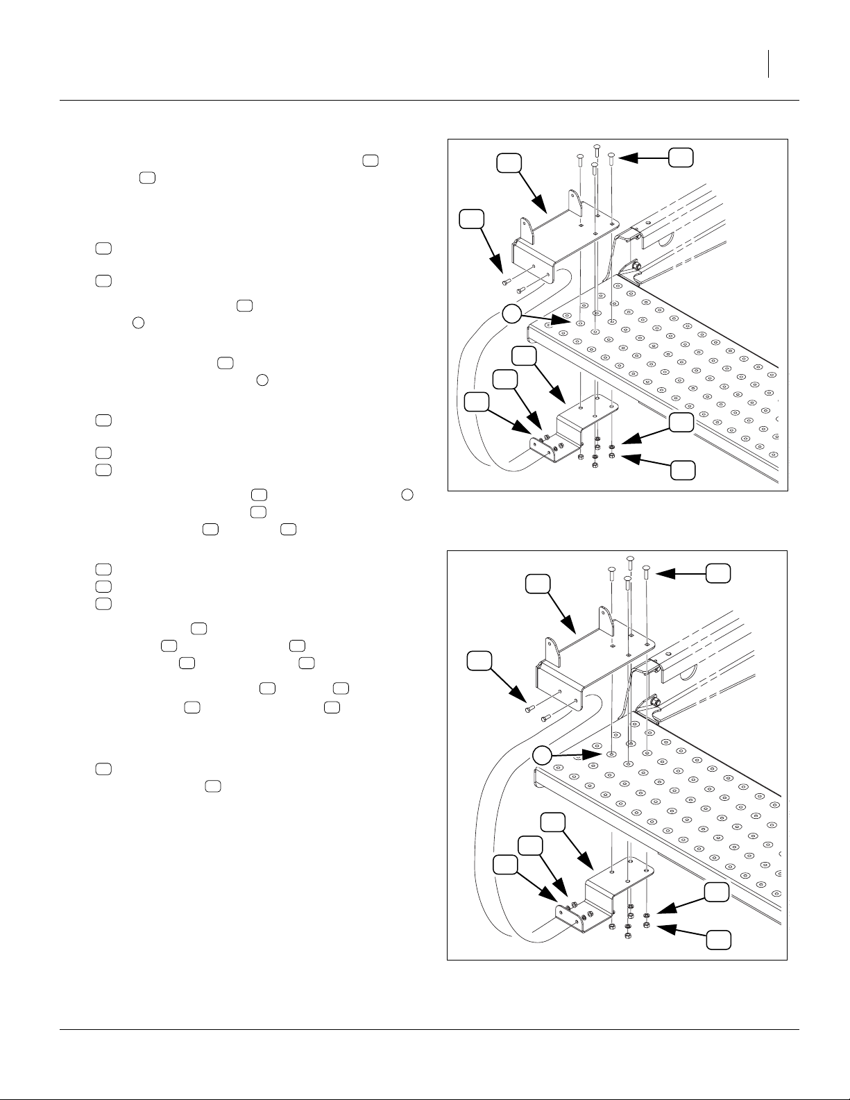
Where to place the top ladder mount depends on the drill
configuration.
If the drill has the Small Seeds Box installed (or will be),
the outer rear hole of the mount is the second row from
the rear edge of the walkboard (see Figure 3 on page 3).
If Small Seeds is not installed, the corner mount hole is
the third row from the rear edge (see Figure 4 on
page 3).
Regardless of drill configuration, the outer rear hole of
the top mount the second row in from the end of the
walkboard.
53
51
Figure 2
Remove Left Step
U
F
L
R
B
D
27035
195-066M 09/10/2007
Page 3
Great Plains Manufacturing, Inc. Install Ladder Mounts 3
Refer to Figure 3 or Figure 4
Top mount weldments are provided in left-side ( ) and
right-side ( ) versions and are not interchangeable. All
other parts may be used on either end. Start with the left
wing:
10. Select one:
13
and four:
17
14
195-063H LADDER MOUNT TOP WELDMENT LH,
802-030C RHSNB 7/16-14X1 3/4 GR5.
13
13
16
17
11. Position the top mount over the four walkboard
4
holes appropriate for the drill’s configuration (see
page 2).
12. Insert the four bolts to loosely hold the top mount
in place on the walkboard .
13. Select one:
15
195-340D LADDER MOUNT BOTTOM PLATE
and four sets of:
23
804-014C WASHER LOCK 7/16 PLT
19
803-015C NUT HEX 7/16-14 PLT
14. Position the bottom plate under the walkboard
and inside the top mount . Loosely hold it in place
with the washers and nuts .
15. Select two sets of:
16
802-017C HHCS 3/8-16X1 GR5
22
804-013C WASHER LOCK SPRING 3/8 PLT
20
803-068C NUT HEX FLANGE 3/8-16 PLT
16. Insert the bolts through the side holes in both the
top mount and bottom plate , and secure with
lock washers and flange nuts .
17. Tighten the four
the top mount to the bottom plate .
16
13 15
22 20
7
13 15
13
17
4
15 4
13
23 19
⁄
in nuts on bolts , securing
16
19 17
22
16
4
15
20
Figure 3
Small Seeds Mount Location
13
23
19
27055
17
Refer to Figure 7 on page 6
18. Selecting one:
14
195-064H LADDER MOUNT TOP WELDMENT RH
in place of mount , repeat step 10 through step 17
for right wing section.
13
4
15
20
22
23
19
Figure 4
Location, No Small Seeds
09/10/2007 195-066M
27036
Page 4

4 Ladder Kit Great Plains Manufacturing, Inc.
Install Ladders
The ladders mount between the lugs of the upper
mounts. Flat washers are placed outside the ladder side
frames and inside the lugs (between ladder side frame
and mount). Bolt heads are to the inside, to minimize
obstructions to foot movement during climbing.
Refer to Figure 5
(which shows only the left side assembly,
on a drill without Small Seeds)
Start with the left walkboard.
19. Select one:
12
195-062H
LADDER WELDMENT 3-STEP NARROW
12
13
20. Lay the ladder on the walkboard with the swing
holes up and near the top mount lug holes. Align
12
13
the holes in the ladder in between the holes in the
lugs.
21. Select two sets of:
18
802-079C HHCS 3/8-16X1 1/4 GR5
24
804-016C WASHER FLAT 1/2 SAE PLT
21
803-209C NUT FLANGE LOCK 3/8-16 PLT
22. Insert a bolt through (in this order):
• the ladder side plate,
• a washer , and
• the mount lug.
Secure with lock nut .
18
12
24
13
21
23. Repeat step 19 through step 22 for right wing walkboard.
24. Swing both ladders down to check operation and
position for decal placement.
18
Figure 5
Ladder Installation
21
24
27037
195-066M 09/10/2007
Page 5

Great Plains Manufacturing, Inc. Install Reflectors and Decals 5
Install Reflectors and Decals
The new ladder top mount may obscure existing decals
and reflectors on the walkboard. The ladder kit includes
replacements to apply as needed.
To install new reflectors and decals:
• Clean and dry the area where the reflector or decal
is to be placed.
• Peel backing from reflector or decal. Press firmly
on surface, being careful not to cause air bubbles
under reflector or decal.
Refer to Figure 6
Start on the left walkboard, outer end:
25. Select one:
26
838-265C DECAL REFLECTOR AMBER 1 1/2X9
25
Place the reflector decal on the outside of the ladder
mount , between the ladder side plates (so it
won’t be damaged by ladder operation)
26. Select one:
26
Place the reflector decal on the rear and corner of the
ladder mount . This decal is slightly longer than
that side of the mount. Wrap the excess around the
corner.
27. Select one:
25
Place the 838-102C Danger decal forward of and
near the top of the ladder, where it is visible to climbers.
28. Repeat step 25 through step 27 for right wing walkboard ladder.
13 12
838-265C DECAL REFLECTOR AMBER 1 1/2X9
13
838-102C
DECAL WARNING FALLING HAZARD
25
Operations
Swing ladders up and onto walkboards during:
• folding and unfolding,
• transport,
• field operations,
• unattended parking, and;
• storage.
12
26
Figure 6
Replacement Decals
26
13
27016
09/10/2007 195-066M
Page 6

6 Ladder Kit Great Plains Manufacturing, Inc.
Parts Lists
New Parts: Kit 195-065A
25
17
26
24
18
12
13
16
15
Your kit includes the parts illustrated above and listed
below. The part call-out numbers in this list match all Figures in the installation instructions.
20
Figure 7
New Parts
21
14
23
19
27034
Left- and right-hand kit parts are identical except for:
top mount: Left: , Right: .
13 14
Callout Quantity Part Number Part Description
11
12
13
14
15
16
17
18
19
20
21
22
23
24
25
26
195-066M 09/10/2007
1 195-066M This manual (not shown above)
2 195-062H LADDER WELDMENT 3-STEP NARROW
1 195-063H LADDER MOUNT TOP WELDMENT LH
1 195-064H LADDER MOUNT TOP WELDMENT RH
2 195-340D LADDER MOUNT BOTTOM PLATE
4 802-017C HHCS 3/8-16X1 GR5
8 802-030C RHSNB 7/16-14X1 3/4 GR5
4 802-079C HHCS 3/8-16X1 1/4 GR5
8 803-015C NUT HEX 7/16-14 PLT
4 803-068C NUT HEX FLANGE 3/8-16 PLT
4 803-209C NUT FLANGE LOCK 3/8-16 PLT
4 804-013C WASHER LOCK SPRING 3/8 PLT
8 804-014C WASHER LOCK 7/16 PLT
4 804-016C WASHER FLAT 1/2 SAE PLT
2 838-102C DECAL WARNING FALLING HAZARD
4 838-265C DECAL REFLECTOR AMBER 1 1/2X9
Page 7

Great Plains Manufacturing, Inc. Parts Lists 7
Existing Parts Affected
54
55
53
51
Existing Parts Affected
The following existing parts may be involved in the kit
installation. The Disposition column indicates whether
parts are left in place, moved or not re-used.
Figure 8
The part call-out numbers in the list match all Figures in
the installation instructions. Descriptions match those in
your drill Parts manual.
52
Existing Parts List
Callout Part No. Part Description Part Disposition
51
195-121D STEP LH Removed. Not re-used.
52
195-122D STEP RH Removed. Not re-used.
53
802-082C HHCS 1/2-13X1 3/4 GR5 Saved and re-used.
54
803-020C NUT HEX 1/2-13 PLT Saved and re-used.
27035
55
804-015C WASHER LOCK SPRING 1/2 PLT Saved and re-used.
09/10/2007 195-066M
Page 8

Reference Information
Abbreviations Torque Values
GR Grade
HHCS Hex Head Cap Screw (Bolt)
LH Left Hand
PLT Plated
RH Right Hand
RHSNB Round Head Shank Neck Bolt
SAE Society of Automotive Engineers
(mechanical standard)
EOD
Fastener/Fitting Ft-Lbs N-m
3
⁄
-16 Grade 5
8
7
⁄
-14 Grade 5
16
1
⁄
-13 Grade 5
2
31 42
67 49
105 76
Great Plains Manufacturing, Inc.
Corporate Office: P.O. Box 5060
Salina, Kansas 67402-5060 USA
 Loading...