

Page 1
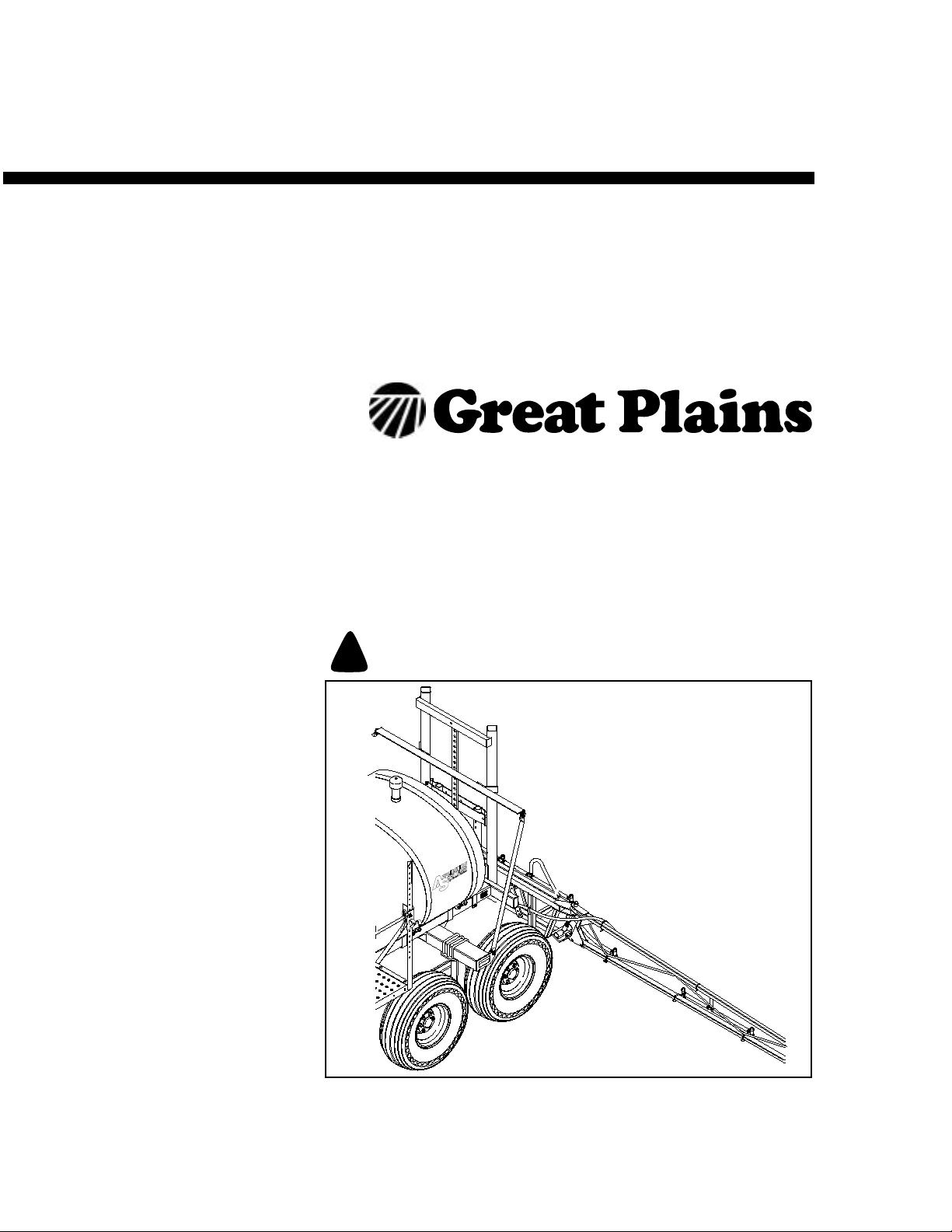
Operator’ s Manual
1993+ MF30, MF40 & MF45
Manual Fold Sprayer Booms
Manufacturing, Inc.
Read the operator’s manual entirely.Whenyouseethissymbol, the subsequent
instructions and warnings are serious - follow without exception. Your life and
!
the lives of others depend on it!
20233
12234
Cover illustration may show optional equipment not supplied with standard unit.
© Copyright 1997 Printed 4/15/2003
500-048M
Page 2

Table of Contents
Important Safety Information. . . . . . . . . . . . . . . . 1
Wear Protective Equipment . . . . . . . . . . . . . . . 5
Handle Chemicals Properly . . . . . . . . . . . . . . . 6
Safety Decals . . . . . . . . . . . . . . . . . . . . . . . . . 8
Introduction. . . . . . . . . . . . . . . . . . . . . . . . . . . . . . 9
Description of Unit . . . . . . . . . . . . . . . . . . . . . . 9
Intended Usage . . . . . . . . . . . . . . . . . . . . . 9
Models Covered. . . . . . . . . . . . . . . . . . . . . 9
Using This Manual . . . . . . . . . . . . . . . . . . . . . . 9
Definitions . . . . . . . . . . . . . . . . . . . . . . . . . 9
Owner Assistance . . . . . . . . . . . . . . . . . . . . . . 9
Preparation and Setup . . . . . . . . . . . . . . . . . . . . 10
Tractor Requirements. . . . . . . . . . . . . . . . . . . 10
Before You Start. . . . . . . . . . . . . . . . . . . . . . . 10
Sprayer/Boom Assembly Instructions . . . . . . 10
3-Point/Boom Assembly Instructions . . . . . . . 14
Operating Instructions. . . . . . . . . . . . . . . . . . . . 15
Basic Sprayer Operating Procedures. . . . . . . 15
Parking. . . . . . . . . . . . . . . . . . . . . . . . . . . . . . 15
Transporting . . . . . . . . . . . . . . . . . . . . . . . . . . 17
General Notes For Field Operation . . . . . . . . 18
Operating Checklist . . . . . . . . . . . . . . . . . . . . 18
Adjustments. . . . . . . . . . . . . . . . . . . . . . . . . . . . .19
Boom Height. . . . . . . . . . . . . . . . . . . . . . . . . .19
Nozzle Pressure . . . . . . . . . . . . . . . . . . . . . . .19
Break-Away Pivot . . . . . . . . . . . . . . . . . . . . . .19
Troubleshooting. . . . . . . . . . . . . . . . . . . . . . . . . .20
Maintenance and Lubrication. . . . . . . . . . . . . . .21
Maintenance . . . . . . . . . . . . . . . . . . . . . . . . . .21
Equipment Cleanup . . . . . . . . . . . . . . . . .21
General Information . . . . . . . . . . . . . . . . .21
Storage . . . . . . . . . . . . . . . . . . . . . . . . . . . . . .21
Lubrication . . . . . . . . . . . . . . . . . . . . . . . . . . .21
Swing Arm Pivot Joints. . . . . . . . . . . . . . .21
Break-Away Boom Pivot. . . . . . . . . . . . . .22
Hinge Tube Pivot. . . . . . . . . . . . . . . . . . . .22
Outer Fold Arm Pivot . . . . . . . . . . . . . . . .22
Specifications and Capacities . . . . . . . . . . . . . .23
Appendix . . . . . . . . . . . . . . . . . . . . . . . . . . . . . . .24
Torque Values Chart . . . . . . . . . . . . . . . . . . . .24
Warranty . . . . . . . . . . . . . . . . . . . . . . . . . . . . .25
© Copyright 1997Allrights Reserved
Great Plains Manufacturing, Inc. provides this publication“as is” without warranty of any kind, either expressed or implied. While every precaution has been takenin the
preparationofthismanual,GreatPlainsMan uf acturing,Inc.assumesno responsibility for errorsoromissions.Neither is any liabilityassumedfordamages resulting from
theuseof the information contained herein. Great Plains Manufacturing,Inc. reservestheright to reviseandimproveits products as it sees fit. This publication describes
the state of this product at the time of its publication, and may not reflect the product in the future.
Great Plains Manufacturing, Incorporated Trademarks
The following are trademarks of Great Plains Mfg., Inc.: Application Systems, Ausherman, Land Pride, Great Plains
All other brands and product names are trademarks or registered trademarks of their respective holders.
Printed in the United States of America.
4/15/2003
500-048M
Page 3

Important Safety Information
Look for Safety Symbol
The SAFETY ALERT SYMBOL indicates there is
apotential hazard to personal safetyinvolvedand
extrasafety precaution must be taken. When you
see this symbol, be alert and carefully read the
message that follows it. In addition to design and
configuration of equipment, hazard control and
accident prevention are dependent upon the
awareness, concern, prudence and proper training of personnel involved in the operation,
transport, maintenance and storage of
equipment.
Important Safety Information
!
1
Be Aware of Signal Words
Signal words designate a degree or level of hazard seriousness.
DANGER indicates an imminently hazardous situation which, if not avoided, will result in death or
serious injury. This signal word is limited to the
most extreme situations, typically for machine
components that, for functional purposes, cannot
be guarded.
WARNINGindicates a potentially hazardous situationwhich, if not avoided,could resultin death or
serious injury, and includes hazards that are exposed when guards are removed. It may also be
used to alert against unsafe practices.
CAUTION indicates a potentially hazardous situation which, if not avoided,may result in minor or
moderate injury. It may also be used to alert
against unsafe practices.
DANGER
!
WARNING
!
CAUTION
!
4/15/2003
500-048M
Page 4

1993+ MF30, MF40 & MF45
2
Be Familiar with Safety Decals
▲ Read and understand “Safety Decals,” page 8,
thoroughly.
▲ Read all instructions noted on the decals.
Keep Riders Off Machinery
Riders obstruct the operator’s view.Riders could
be struck by foreign objects or thrown from the
machine.
▲ Never allow children to operate equipment.
▲ Keep all bystanders away from machine dur-
ing operation.
Shutdown and Storage
▲ Fold the Manual Fold Sprayer Boom, put trac-
tor in park, turn off engine, and remove the
key .
▲ Secure Manual Fold Sprayer Boom using
blocks and supports provided.
OFF
▲ Detach and store Manual Fold Sprayer Boom
in an area where children normally do not play.
Use Safety Lights and Devices
Slow-moving tractors and towed implements can
create a hazard when driven on public roads.
They are difficult to see, especially at night.
▲ Use flashing warning lights and turn signals
whenever driving on public roads.
▲ Use lights and devices provided with imple-
ment.
Use A Safety Chain
▲ Use a safety chain to help control drawn
machinery should it separate from tractor
drawbar.
▲ Use a chain with a strength rating equal to or
greater than the gross weight of towed
machinery.
▲ Attach chain to tractor drawbar support or
other specified anchor location. Allow only
enough slack in chain to permit turning.
▲ Replace chain if any links or end fittings are
broken, stretched or damaged.
▲ Do not use safety chain for towing.
500-048M
4/15/2003
Page 5

Transport Machinery Safely
Maximum transport speed for implement is 20
mph. Some rough terrains require a slower
speed.Sudden brakingcan cause atowed loadto
swerve and upset.
▲ Do not exceed 20 mph. Never travel at a
speed which does not allow adequate control
of steering and stopping. Reduce speed if
towed load is not equipped with brakes.
▲ Comply with state and local laws.
▲ Do not tow an implement that, when fully
loaded, weighs more than 1.5 times the weight
of towing vehicle.
▲ Carry reflectors or flags to mark Manual Fold
Sprayer Boom in case of breakdown on the
road.
Important Safety Information
3
▲ Keep clear of overhead power lines and other
obstructions when transporting. Refer to transport dimensions under “Specifications and
Capacities,” page 23.
▲ Do not fold or unfold the Manual Fold Sprayer
Boom while the tractor is moving.
Avoid High Pressure Fluids
Escaping fluid under pressure can penetrate the
skin, causing serious injury.
▲ Avoid the hazard by relieving pressure before
disconnecting hydraulic lines.
▲ Use a piece of paper or cardboard, NOT
BODY PARTS, to check for suspected leaks.
▲ Wear protective gloves and safety glasses or
goggles when working with hydraulic systems.
▲ If an accident occurs, see a doctor immedi-
ately. Any fluid injected into the skin must be
surgically removed within a few hours or gangrene may result.
4/15/2003
500-048M
Page 6

1993+ MF30, MF40 & MF45
4
Practice Safe Maintenance
▲ Understand procedure before doing work. Use
proper tools and equipment. Refer to this manual for additional information.
▲ Work in a clean, dry area.
▲ Fold the Manual Fold Sprayer Boom, put trac-
tor in park, turn off engine, and remove key
before performing maintenance.
▲ Make sure all moving parts have stopped and
all system pressure is relieved.
▲ Allow Manual Fold Sprayer Boom to cool com-
pletely.
▲ Disconnect battery ground cable (-) before
servicing or adjusting electrical systems or
before welding on Manual Fold Sprayer Boom.
▲ Inspect all parts. Make sure parts are in good
condition and installed properly.
▲ Remove buildup of grease, oil or debris.
▲ Remove all tools and unused parts from Man-
ual Fold Sprayer Boom before operation.
Prepare for Emergencies
▲ Be prepared if a fire starts.
▲ Keep a first aid kit and fire extinguisher handy.
OFF
▲ Keep emergency numbers for doctor, ambu-
lance, hospital and fire department near
phone.
Tire Safety
Tire changing can be dangerous and should be
performed by trained personnel using correct
tools and equipment.
▲ When inflating tires, use a clip-on chuck and
extension hose long enough for you to stand
to one side–not in front of or over tire assembly. Use a safety cage if available.
▲ When removing and installing wheels, use
wheel-handling equipment adequate for
weight involved.
500-048M
911
4/15/2003
Page 7

Wear Pr otective Equipment
Great Plains advises all users of chemical pesticides or
herbicides to use the following personal safety
equipment.
▲ Waterproof, wide-brimmed hat
▲ Waterproof apron.
▲ Face shield, goggles or full face respirator.
▲ Goggles with side shields or a full face respirator is
required if handling or applying dusts, wettable powders, or granules or if being exposed to spray mist.
▲ Cartridge-type respirator approved for pesticide
vapors unless label specifies another type of respirator.
▲ Waterproof, unlined gloves. Neoprene gloves are
recommended.
Important Safety Information
5
▲ Cloth coveralls/outer clothing changed daily; water-
proof items if there is a chance of becoming wet with
spray
▲ Waterproof boots or foot coverings
▲ Do not wear contaminated clothing. Wash protective
clothing and equipment with soap and water after
each use. Personal clothing must be laundered separately from household articles.
▲ Clothing contaminated with certain pesticides must
be destroyed according to state and local regulations. Read chemical label for specific instructions.
▲ Wear clothing and equipment appropriate for the job.
Avoid loose-fitting clothing.
▲ Prolonged exposure to loud noise can cause hear-
ing impairment or loss. Wear suitable hearing protection such as earmuffs or earplugs.
▲ Avoid wearing radio headphones while operating
machinery. Operating equipment safely requires the
full attention of the operator.
4/15/2003
500-048M
Page 8

1993+ MF30, MF40 & MF45
6
Handle Chemicals Properly
▲ Read and follow chemical manufacturer’s
instructions.
▲ Wear protective clothing.
▲ Handle all chemicals with care.
▲ Agricultural chemicals can be dangerous.
Improper use can seriously injure persons,
animals, plants, soil and property.
▲ Inhaling smoke from any type of chemical fire
is a serious health hazard.
▲ Store or dispose of unused chemicals as
specified by the chemical manufacturer.
▲ Before adding chemical to the tank, make
sure tank is at least half full. Do not pour concentrate into an empty tank.
▲ Never leave fill hose attached to the sprayer
after filling tank. Chemicals in tank can siphon
out of tank and contaminate freshwater
source.
▲ Always keep hand-wash tank filled with clean
water and have soap available in case of an
emergency. Immediately and thoroughly flush
any area of the body that is contaminated by
chemicals.
▲ Spray only with acceptable wind conditions.
Wind speed must be below 5 mph. Make sure
wind drift of chemicals will not affect any surrounding land, people or animals.
▲ Never wash out the sprayer tank within 100
feet of any freshwater source or in a car wash.
▲ Rinse out the tank. Spray rinse water on last
field sprayed.
▲ Do not touch sprayer components with mouth
or lips.
▲ If chemical is swallowed, carefully follow the
chemical manufacturer’s recommendations
and consult with a doctor.
▲ If persons are exposed to a chemical in a way
that could affect their health, consult a doctor
immediately with the chemical label or container in hand. Any delay could cause serious
illness or death.
▲ Dispose of empty chemical containers prop-
erly. By law rinsing of the used chemical container must be repeated three times. Puncture
the container to prevent future use. An alternative is to jet-rinse or pressure rinse the container.
▲ Wash hands and face before eating after
working with chemicals. Shower as soon as
spraying is completed for the day.
500-048M
4/15/2003
Page 9

Safety At All Times
Thoroughly read and understand the instructions
in this manual before operation. Read all instructions noted on the safety decals.
▲ Be familiar with all Manual Fold Sprayer Boom
functions.
▲ Operate machinery from the driver’s seat only.
▲ Do not leave Manual Fold Sprayer Boom unat-
tended with tractor engine running.
▲ Do not dismount a moving tractor. Dismount-
ing a moving tractor could cause serious injury
or death.
▲ Do not stand between the tractor and Manual
Fold Sprayer Boom during hitching.
▲ Keep hands, feet and clothing away from
power-driven parts.
Important Safety Information
7
▲ Wear snug-fitting clothing to avoid entangle-
ment with moving parts.
▲ Watch out for wires, trees, etc., when folding
and raising Manual Fold Sprayer Boom. Make
sure all persons are clear of working area.
▲ Do not turn tractor too tightly, causing Manual
Fold Sprayer Boom to ride up on wheels. This
could cause personal injury or equipment
damage.
▲ Use only water without pesticides added to
calibrate the sprayer. Do not exceed the calibrated sprayer speed and pressure when
operating.
▲ When using a PTO pump, be sure that PTO
shield is in place on the tractor, PTO coupler
bolts are torqued to the correct specification,
and torque bar is properly chained to tractor
drawbar.
▲ Spray with the boom in the unfolded position
only.
▲ The boom has many pinch points during field
operation and folding. Keep all bystanders
away.
4/15/2003
500-048M
Page 10

1993+ MF30, MF40 & MF45
8
Safety Decals
Your implement comes equipped with all safety
decals in place. They were designed to help you
safely operate your implement.
▲ Read and follow decal directions.
▲ Keep all safety decals clean and legible.
▲ Replace all damaged or missing decals. Order
new decals from your Great Plains dealer.
Refer to this section for proper decal placement.
818-055C
Slow Moving Vehicle Label
Middle rear of center section, one total
▲ When ordering new parts or components, also
request corresponding safety decals.
▲ To install new decals:
1. Clean the area where the decal is to be
placed.
2. Peel backing from decal. Press firmly on
surface, being careful not to cause air
bubbles under decal.
12214
818-335C
Red Reflector
818-367C
Danger Power Line Hazard
500-048M
12215
12299
4/15/2003
Page 11

Introduction
Introduction
9
GreatPlains welcomesyouto itsgrowingfamilyof
new product owners. This Manual Fold Sprayer
Boom has been designed with care and built by
skilled workers using quality materials. Proper
setup, maintenance and safe operating practices
willhelp you get yearsof satisfactory use from the
machine.
Description of Unit
The MF30, MF40 and MF45 sprayer booms are
capable of spraying at either 30’, 40’ or 45’ depending on your model.
Intended Usage
Usethese booms aspart ofa pressurized sprayer
system to apply liquid pesticides, herbicides or
fertilizers to production-agriculture crops only.Do
not modify sprayerfor use with attachments other
than those approved by Great Plains.
Models Covered
MF30, MF40 and MF45
Using This Manual
This manual will familiarize you with safety, assembly, operation, adjustments, troubleshooting
and maintenance. Read this manual and follow
the recommendations to help ensure safe and efficient operation.
The information in this manual is current at printing. Some parts may change to assure top
performance.
Definitions
The following terms are used throughout this
manual.
Owner Assistance
If you need customer service or repair parts, contact a Great Plains dealer. They have trained
personnel, repair parts and equipment specially
designedforManualFoldSprayerBoom products.
Your machine’sparts werespeciallydesigned and
should only be replaced with Manual FoldSprayer
Boom parts. Always use the serial and model
number when ordering parts from your Great
Plains dealer.
Record your sprayermodel and serial number
here for quick reference:
Model Number:__________________________
Serial Number: ___________________________
Your Great Plains dealer wants you to be satisfied
with your new machine. If you do not understand
anypart of this manualor are not satisfied with the
service received, please take the following
actions.
1. Discussthematterwithyourdealershipservice
manager.Make sure they are aware of any
problems so they can assist you.
2. If you are still unsatisfied, seek out the owner
or general manager of the dealership.
3. For further assistance write to:
Product Support
Great Plains Mfg. Inc., Service Department
PO Box 5060
Salina, KS 67402-5060
4/15/2003
Right-hand and left-hand as used in this manual
are determined by facing the direction the machine will travel while in use unless otherwise
stated.
IMPORTANT: A crucial point of information related to the preceding topic. For safe and correct operation, read and follow the directions
provided before continuing.
NOTE: Useful information related to the preceding topic.
500-048M
Page 12

1993+ MF30, MF40 & MF45
10
Preparation and Setup
Tractor Requirements
When using a 3-point boom, the tractor must havea standard Category II, Category II Quick Hitch, or a Category
III-narrow 3-point.
Before You Start
Read and understand the ownersmanualfor your sprayer
boom. A basic understanding of how the boom works will
aid in the assembly and set up of your sprayer boom.
Before attempting to assemble the boom, use the following as a checklist. Having all the needed parts and equipmentreadily at handwill speed up yourassembly taskand
will make the job as safe as possible.
1. Check for all sprayerboom components and hardware. The loose components used to fasten the
booms are packaged in a box with a packing list and
are shipped with the crate.
2. If a bolt,pin or othercomponent has been removed,or
if you are unsure about where it is used, refer to the
parts section of this manual to identify it.
3. Have a fork lift or loader present to lift the booms
wings when assembling the sprayer boom.
4. Two people are required to assemble boom.
Sprayer/Boom
Assembly Instructions
Refer to Figure 1
1. Position the sprayer trailer in a clear, level area with
the jack placed in the park position. Adjust the jack so
that the sprayer tank is level and the elevator mast is
straight up and down.
2. Adjust the elevatorlocated on the pull-type sprayerto
thelowestposition. Refer tothesprayer Owner’sManual for elevatoradjustment instructions.
3. Install the center section of the boom (16) with the
hardware(17) provided if installed on a 3-Pointboom,
a TA500, or a TA520 sprayer. If the boom is installed
on another sprayer, install the hardware with the following modifications:
If the boom is attached to a 3P200/300 3-Point sprayer,the 501-027S accessory kit must bepurchased. Installthe spacer tube (4) asillustrated in Figure 2using
the bolts (5), nuts (7), and flat washers (6).
When attaching the boom to a SA750, SA700, or
SA1000sprayer,the 506-086Vkit mustbepurchased.
Assemble the spacer tubes (22) as illustrated in Figure1 in between theboom center section (16) andthe
elevatorusing the hardware provided.
When mounting the boom on a TS sprayer,refer to
Figure 4. To mount the boom on the TS sprayer, the
506-129V kit must be purchased. Assemble the center section of the boom onto the elevator with the
spacer blocks (1) in between.
4. Insert the level-floatlock pin (21)intoit'slock position,
as shown, if not already done.
5. Before installing a boom wing (14), make sure the outerboom frame is foldedover andfastened to the inner
boom frame with the transport pin or a cable tie as
shown (13). With the outer boom frame folded, it is
easier to maneuver the boom wing during assembly.
6. To assemble a boom wing, hook the round tubing of
the boom wing (14) into the upper hinge brackets of
the center boom section. Use a forklift or loader to lift
the weight of the boom wing.
7. Assemble the pivot rod (4) and nut (3) through the
hinge components shown. Assemble the washer (8)
so that it’s smaller diameter fits down into the spring
(7). With a 1/2 inch open end wrench, hold the top of
the pivot rod while tightening the top (9) and bottom
(3) nuts to compress the spring. Tighten the nuts
evenlyso they have approximately the same thread
depthon the pivotrod, and the dimension from thetop
of the round pivot bar to the flat washer above the
spring is 5 3/8 of an inch. Repeat steps 5, 6, and 7 for
the other boom wing.
8. With the boom wings unfolded, assemble the 1/2" x 1
3/4" long bolts, flat washers, and flange nuts (5). Before tightening, align outer boom sections with the
center section of the boom by rotating plate (6).
Torque the nuts to 85 foot-pounds.
9. Install and centerthenozzle bar (18) tothe center section of the boom with the 5/16" x 3" long bolts and
flange nuts (19). Torque the nuts to 18 foot-pounds.
10. Attach the feed-line hoses (15) from the center frame
nozzle bar to the nozzle(s) on the boom wings (14)
with the hose clamps provided.
11. Remove cap plugs on solenoid hose barbs (located
on the sprayer) and attach boom feed-line hoses (10,
11 and 12) from the three separate boom sections to
the electric solenoids with the hose clamps provided.
Make sure that the left boom feed-line hose is connected to the front hose solenoid {front being toward
thehitch}.Thelefthoseandsolenoidare markedwith
a red tape. The center boom feed-line hose (11) is
connected to the middle solenoid. The middle hose
and solenoid are marked with a yellowtape. The right
boom feed-line hose (12) is connected to the back solenoid.Theright hose and solenoid are markedwith a
green tape.
Ifthe boom isgoing to bemounted on thetandem axle
sprayerthat has front folding booms, route the boom
hoses in front of the boom break-awaypivot (4)
through the hose supports located on the front of the
boom center section and through the supports under
the sprayer trailer.
500-048M
4/15/2003
Page 13

Preparation and Setup
11
Ifthe boom is going to be mounted on a SingleAxle or
Trailer Sprayer with rear folding booms, route the
boom hoses in back of the boom break-away pivot,
through the hose supports located on the front of the
boom center section, and through the supports under
the sprayer.
12. If the boom is being attached to a Great Plains TA500
or TA520 TandemAxle Sprayer,adjust the boom fold
latches (2) to the desired boom height and fold the inner boom sections forward. If the fold latch interferes
with a nozzle on the folded boom, use the extension
brackets(1) to reposition the boom fold latches. Refer
to Field Adjustments in the Tandem Axle Sprayer
Owner’sManual for more information. Fasten the fold
latch on the tandem axle sprayerto secure the boom.
13. Fold and unfold the boom wings to check any pinch
points where the hose maybecome damaged. Unfold
the boom, remove the boom level-float lock pin (21)
and rock the boom to check any pinch points around
the swing-bars (20). Use the cable-ties included to
fasten hoses in such a way as to prevent hose damage.
14. Whenattaching the manualfoldboom toa 3P200/300
3-Point sprayer, the 501-027S accessory kit must be
purchased. Refer to Figure 2 for the assembly of the
fold brackets. Attach the boom supports (3) to the
sprayerframe using the u-bolts(2) and nuts (1)provided. Center the boom supports (3) on the sprayer
frame.
If the boom is being attached to a Great Plains Single
Axle Sprayer,you must purchase the 506-087V accessory kit and assemble the fold bracketsas illustrated in Figure 3. Attach the fold brackets (1) as you
position the painted spacer washers (2) in the bottom
holes between the elevatorand the fold brackets (1).
To mount the fold bracketson a TS sprayer, refer to
Figure 4. Mount the fold brackets(2) with the spacer
blocks (1) in between the fold bracketsand the elevator as illustrated.
15. Whenassemblingthe manual foldboomto 200/300 3Point Sprayer, you need to have a 501-027S
3-PointTank Sprayermanualfoldboom mount. Attach
the boom supports (3) with the 1/2” u-bolts (2) and
1/2” flange nuts (1). Attach the with spacer blocks (4)
and1/2” x4”bolts (5),1/2” washers(6)and 1/2”flange
nuts (7). Refer to Figure 2.
16. Check to see all nuts are tightened. See Torque Val-
ues Chart for Common Bolt Sizes in Appendix for ad-
4/15/2003
Figure 1
Manual Fold Boom Assembly Illustration
11945
500-048M
Page 14

1993+ MF30, MF40 & MF45
12
ditional torque specifications. Check to see that all
hose clamps are tight.
17. Fill the sprayer tank 1/4 full of water. Hook up the
pumpto a tractor as described in the SprayerOwner’s
Manual. Operate the pump with the control box boom
switches off and the agitation wide open. If unit is
equipped with solenoid throttling valves open throttling valves full open. With the pump running, turn on
all the boom switchesand flush out the boom lines beforeassemblingthenozzles. Allow waterto flow outof
all nozzles at least ten seconds to ensure all foreign
matter is removed from the plumbing.
18. Assemble the nozzles onto the nozzle check valves
and operate each section. If storing unit, refer to Stor-
age in the SprayerOwner’s Manual.
14313
Figure 2
Fold Bracket Assembly Illustration {3-Point}
500-048M
11954
Figure 3
Fold Bracket Assembly Illustration {Single Axle}
4/15/2003
Page 15

Preparation and Setup
13
14359
12243
Figure 4
Fold Bracket Assembly Illustration {Trailer Sprayer}
Figure 5
Hitch Pin Configuration
4/15/2003
500-048M
Page 16

1993+ MF30, MF40 & MF45
14
3-Point/Boom
Assembly Instructions
1. Refer to Figure 5 on page 13 to determine the pin and
spacer configuration needed for your tractor.
Mount the 3-point attachment (1) to a tractor with the pins
provided.
Makesure that the 3-point attachment is levelso that after
the boom is assembledit will not hit the tractor when the 3point is raised.
2. Follow Step 3 through Step 10 under Sprayer/Boom
Assembly Instructions beginning on page 10 to complete the assembly of the boom.
Refer to Figure 6
3. Attach the fold bracket (4) to the 3-point attachment
(1) with the four 1/2" x 4" long bolts (5), 1/2" flange
nuts (7), and flat washers (6). Assemble the coupler
bracket (8) as shown when you assemble the fold
bracket.
4. Fasten the male fluid connectors (2) to the coupler
bracket(8) with the coupler clamps (9). Use the 5/16"
x 3/4" long bolts and 5/16" flange nuts to secure the
coupler clamps.
5. Attach boom line hosesfromthe three separate boom
sectionsto thecam-lock malefluid connectors(2) with
the hose clamps provided. Make sure to route the
boom hoses behind the boom break awaypivot (Figure 1 (4)) so that when the boom foldsto the back, the
hoseswill not stretch. Youwill need to route the hoses
from your tractor to the cam-lock female fluid connectors (3), which fasten into the stationary male fluid
connectors mounted on the 3-point frame.
6. If the 3-point boom is being mounted on a tractor with
Great Plains side-mount tanks, removethe cap plugs
on the solenoid hose barbs and route the left boom
feed-line hose from the corresponding female fluid
connector to the right solenoid {right being as you sit
in the tractor} marked with red tape. Connect the center boom feed-line hose from the corresponding female fluid connector to the middle solenoid marked
withyellow tape. Nowconnect the right feed-line hose
from the corresponding female fluid connector to the
left solenoid marked with green tape.Take care when
routing the boom hoses to the tractor to ensure there
willbe nokinking, drooping,hanging belowthe tractor,
orrubbing on thetractor frame whenin operation. Use
cable ties to fasten and protect the hose.
7. Fold and unfold the boom wings and check for any
pinch points where the hose may become damaged.
Unfoldthe boom, remove the boom level float lockpin
(Figure 1 (21)) and rock the boom to check any pinch
points around the swing bars (Figure 1 (20)). Use the
includedcableties tofasten thehoses insuch awayto
preventhose damage.
8. Check to see all nuts are tightened. See Torque Val-
ues Chart for Common Bolt Sizes in Appendix for additional torque specifications. Check to see that all
hose clamps are tight.
Fill the sprayer tank 1/4 full of water.Hook up the pump to
a tractor and operate the pump with the control box boom
switches off and the agitation wide open. If unit is
equipped with solenoid throttling valves open throttling
valves full open. With the pump running, turn on all the
boom switches and flush out the boom lines before assemblingthe nozzles.Allow water toflow out ofall nozzles
at least ten seconds to ensure all foreign matter is removed from the plumbing.
11955
500-048M
Assemble fold bracket like
shown in Figure 2 on Page 12.
Figure 6
3-Point Assembly Illustration
4/15/2003
Page 17

Operating Instructions
Basic Sprayer
Operating Procedures
1. Make sure to read the label on the chemical compound that is to be applied. It is the law.
2. Consider howthe chemical willbe stored andhow you
willdispose ofthe chemical,according tothe chemical
label.
3. When calibrating, filling the tank, or working around
chemicals, wear protective clothing that covers the
body. Referto WearProtective Equipment on page 5.
Have soap and clean water available to wash any exposed areas. Never open a container with your bare
hands.
4. When filling thesprayer,itis better to mixthe chemical
in the field where it is to be applied. Positionthe sprayer 100 feet from any well or other water source before
mixing chemical.
5. By law, you must repeat the rinsing of the chemical
container 3 times. The container should then be punctured to prevent future use. An alternative is to jetrinse or pressure rinse the container.
6. Check the condition of hoses and connections frequently. Release system pressure before working on
the sprayer by shutting off the pump and flipping the
individual boom section switches on the control box.
always wear rubber gloves when making repairs or
adjustments.
7. Apply spray when the wind is 5 m.p.h. or less. Minimizedrift byusing nozzletipswith thelargest practical
openings and by operating the sprayerboom at the
lowest practical height and lowest practical pressure.
Refer to Figure 7
8. After unfolding the boom, remove the level float pin
and place it in the storage position.
Operating Instructions
NOTE: If possible, do not operate your Great Plains
Sprayer boom without first unlocking the level-float
pin. The boom will float over the contours of the
ground more effectively and minimize stress on the
boom.
9. Drive at the same speed you used in your calibration.
Refer to SprayerCalibrations in the Sprayer Owner’s
Manual. Keep your sprayer calibrated.
10. If possible work crosswise to the wind, starting from
the downwind side of the field. Do this so you won’t
everbe heading directly into chemical fumes.
11. Take note of adjoining crops, houses, gardens, people, etc.
12. When you are finished spraying, empty the tank and
flush the sprayer with water, including the pump, the
nozzlesand the by-pass linefrom the solenoids. Properly store the chemical emptied from the tank or dispose of it by the recommendations on its label.
13. When turning at the end of a field, make sure you are
correct on the rows so that the boom will not overlap
on crop previously sprayed.
15
Parking
The following list should be followedwhen you want to unhook your boom.
1. Flush the boom out with antifreeze (Great Plains
strongly recommends the use of recreational vehicle
antifreeze)to preventdamage to components when a
freeze occurs.
Refer to Figure 8
2. Lock the level float pin and fold the booms.
4/15/2003
Storage Position For
Level Float Pin
Figure 7
Level -Float Pin In Storage Position
12004
12005
Lock Position For
Level Float Pin
Figure 8
Level-Float Pin In Lock Position
500-048M
Page 18

1993+ MF30, MF40 & MF45
16
3. Maneuver the tractor where the boom will be parked.
The storage position for the boom should be in a flat,
levelarea where wind cannot blow it over and preferablywhere it is sheltered from direct sunlight and rain.
Refer to Figure 9
4. Assemble the parking stands as illustrated. if you are
parking a 3-Point boom. As a safety precaution, you
have to fold out the boom wings before these stands
can be assembled.
Refer to Figure 10
5. If you are parking a 3-Pointsprayer, assemble the
parking stand on the back of the 3-PointSprayer as illustrated.
6. If the ground is soft, place a board or plate under the
support to widen the ground contact area.
7. Lower the 3-Pointon the tractorand bring the boom to
rest on the parking stands.
8. Unhook the PTO pump or unplug hydrauliclines from
the hydraulic pump, which ever is applicable.
9. Unhook the cam-lock connectors from the boom as
well as the hydraulic hoses and position them so they
are resting on the frame of the boom.
10. Remove the 3-Point pins from the tractor and pull the
tractor away from the boom.
14923
Figure 9
3-Point Stand Assembly
NOTE: If the sprayer is being hitched up and operated forthe first time, it is important to followthe safety,
set up, adjustment, and operating information in the
front of this manual.
Referto3-Point/BoomAssembly Instructions, onpage 14,
when you are preparing to hitch the sprayer to the tractor.
14924
500-048M
Figure 10
3-Point Sprayer Stand Assembly
4/15/2003
Page 19

Transporting
For transporting a boom mounted on a tandem axle
sprayer.
Refer to Figure 11
1. Park your sprayer in an open area where you will not
hit power lines, buildings, etc. when the boom is folded.
2. Secure the level-floatpin inthe lock position,Figure8,
page 15.
3. Fold the outer boom wings over and fasten the clevis
pin (1) into the fold post on both wings of the sprayer.
4. Fold the boom wings forward and position the boom
wing on the fold latch. If the fold latch happens to be
positioned where a hose fitting or nozzle is, you will
need to reposition the fold latch with the fold latch extension (3). Unbolt the fold latch extension and use it
to reposition the fold latch. Discard the fold latch extension if not needed.
5. Position the fold latch lever(2) in the down position to
secure the boom for transport.
Fortransporting a 3-point boom mounted on a single axle
sprayer.
Operating Instructions
11587
Figure 11
Tandem Axle Sprayer Boom Trans-
port Illustration
17
Refer to Figure 12
1. Fold the left boom wing up and fastenthe corresponding lynch pin (1). Secure the safety wire on the lynch
pin.
2. Fold the right boom wing and fasten the corresponding lynch pin (1). Secure the safety wire on this lynch
pin as well.
3. Do not exceed 20 mph transporting your sprayer.
4. Do not transport sprayerwhile filled with chemical
mixture.Never allow riders when transporting the
sprayer.
5. When transporting your sprayer, be sure to watch the
height clearances of your folded boom to prevent
damage to the boom and possible injury.
!
DANGER
Contact with electrical power lines can cause death by electrocution.
11956
Figure 12
Single Axle Sprayer Or 3-Point Mounted Boom
Transport Illustration
4/15/2003
500-048M
Page 20

1993+ MF30, MF40 & MF45
18
General Notes For Field Operation
1. Securely hitch the sprayer to the tractor or the 3-point
boom to the tractor.
2. Lubricatethe sprayerboom as needed. Referto Lubri-
cation on page 21.
3. When transportingthesprayer,do notexceed20 mph
and do not transport with chemical inthe tank. Fasten
thelevel-floatpin in the lockposition beforefolding the
booms. Before transporting fasten the sprayer fold
latch if mounted on a tandem axle, see Figure 3-5 on
page 12. If the boom is mounted on a single axle or a
3-point, secure the transport lynch pins before transporting. See Figure 12, page 17.
4. Never allow anyone to ride on the sprayer.
5. Calibrate the sprayer with water only, not chemical
and water. Refer to the calibration procedures in the
Application Guide.
6. Remove the level-floatpin from the lockposition,after
being transported and unfolded, to the storage position. See Figure 7, page 15.
NOTE: If possible, do not operate your Great Plains
Sprayer Boom without first unlocking the level-float
pin. The boom will float over the contours of the
ground more effectively and minimize the stress on
the boom.
10. Check the sprayerinitially and periodically for loose
bolts, pins and hose clamps. Check the hoses,
pumps, valves and fittings for leaks.
Operating Checklist
Check
“Safety Rules” in this Manual
The tractor’s brak es to make sure the y operate properly.
Lubricate the boom as needed.
Booms must be locked in place before tr ansporting.
Use safety equipment as listed on page 1.
Fill with water and calibrate spray er BEFORE adding chemical to
the tank.
Check hoses, pumps and valv es for an y leaks.
Check nozzles for streaks and non-uniformity.
Check sprayer initially and periodically f or loose bolts, pins and
chains.
7. Adjust the boom height required for the nozzles and
spacing to be used. (Refer to nozzle tables in the
SprayerManual or the Application Guide.)
8. Check the nozzles for streaks and non-uniformity. If
cleaning the nozzles, wear Personal Safety Equip-
ment and use a nozzle brush. Do not blow on the nozzle or place your lips on the nozzle.
9. Safely and carefully add the chemical to the sprayer
tank. Always wear "Personal Safety Equipment" as
shown on page 5. By law, you must repeat the rinsing
of the chemical container three times. The container
should then be punctured to preventfuture use. An alternativeistojet-rinseorpressurerinsethecontainer.
When adding chemical, remain at least 100 feet from
any water well or fresh water source. Follow chemical
manufacturer’srecommendations forsafe handling of
chemicals.
500-048M
4/15/2003
Page 21

Adjustments
Boom Height
After calibrating your sprayer for the specific nozzle you
will useatadesiredpressure,and tractor speed, the main
field adjustment is the boom height. Refer to Elevator Op-
tion in the Sprayer Owner’s Manual. Depending on which
type of nozzle you are using, you need to set your boom
height so that you achieve the correct overlap for that specific nozzle. If the crop canopy is taller in some fields than
others, you will need to adjust the boom height accordingly. Refer to the nozzle charts located in the SprayerOwner’s Manual or the Application Guide to determine the
height of the boom needed.
EXAMPLE: A 2.5 Metercone nozzle at 20 inch spacing is
being used. From the nozzle chart (refer to the Sprayer
Owner’s Manual or the Application Guide), a height of 19
to 21 inches above the top of the crop is required. If the
cropis6inchesoff the ground, the boom height should be
set to 25 to 27 inches off the ground.
After setting your boom height on the booms mounted on
the Tandem Axle Sprayers,there maybe a need to adjust
thefoldlatchwhen theboom is readyto be folded.Referto
Figure 11, page 17. If a hose fitting or nozzle ispositioned
where the fold latch is located, the fold latch needs to be
offset with the foldlatch extension provided. The foldlatch
extensioncan be mounted in the forward or rear direction;
in any direction the fold latch needs to be repositioned. After repositioning the fold latch, be sure to torque bolts to
the specifications listed in the Torque Values Chart for
Common Bolt Sizes in Appendix. If boom height is in the
lower ranges, you may want to raise the boom for transport. Refer to Elevator in the Sprayer Owner’s Manual.
Adjustments
19
Nozzle Pressure
Another area that will need some field adjustments is the
nozzle pressure. As your tank leveldecreases, you may
haveto adjust the boom pressure to keep the pressure at
the same magnitude for what the sprayer was calibrated
for. Watch your pressure gauge and be aware of changes
in the pressure.
Break-Awa y Pivot
The boom break-away pivot spring should be adjusted so
thatthe compressed length is53/8 of an inch.If the spring
is not compressed to 5 3/8", the boom will tend to break
awayover bumps and wear out the break-away mechanism. Refer to step 7 under Sprayer/Boom Assembly In-
structions on page 10, along with Figure 1 on page 11.
4/15/2003
500-048M
Page 22

1993+ MF30, MF40 & MF45
20
Troubleshooting
Problem Problem Area Specific Checks Corrections
Pressure Increasing
Between Gauge & nozzle
Boom hoses becoming
clogged
Boom hoses pinched Use cable ties to position hose
Remove obstruction from
clogged area.
so it will not kink.
500-048M
4/15/2003
Page 23

Maintenance and Lubrication
Maintenance and Lubrication
21
Maintenance
Proper servicing and adjustment is the key to the long life
of any farm implement. With careful and systematic inspection, you can avoid costly maintenance, time and repair.
Equipment Cleanup
Nozzles should be cleaned with a low pressure (less than
30 psi) air hose, and periodically replaced. Haul a supply
tank of water so you can clean the spray tank and applicator out in the field. Never wash tank out in the yard or at a
car wash.
Dispose of left-over chemical in the same manner described on the manufacture’s label of the chemical last
usedinthe sprayer.Rinse out the tankandspray the rinse
water on the last field that was sprayed.
General Information
If equipment is to be used in freezing or near freezingconditions, protect pump and plumbing system by thoroughly
draining liquid and pumping antifreeze solution through
system to coat the interior of the pump and plumbing.
Before working on, servicing or making adjustments on
sprayer, always disengage power, shut off tractor engine,
makesureallmovingparts havestopped,and allpressure
in the system is relieved.
Checktheconditions ofhoses andconnections frequently.
Releasethe system pressure beforeworking on the sprayer.To release the pressure flip the boom section switches
on and off without the pump running. Alwayswear rubber
gloveswhen makingrepairs or adjustments.Make sure all
Protective Equipment (gloves,goggles, etc.) listed on
page 5, are stored in an easily accessible place but protected from potential contamination from dust or chemicals.
Check the sprayerfor any loose bolts, pins, and hose
clamps.
Checkthe hoses, pumps, valves,andfittingsfor any leaks.
Inspect all parts of the sprayer for wear and rust. Repair
and paint parts as necessary.
Storage
1. Empty solution from your sprayertank and store or
disposeof the chemical as recommended bythemanufacturer’s chemical label.
2. Change filters in the tractor cab after finished.
3. Wash off the exterior of the boom thoroughly using a
safe solvent or soap and water.
4. Flush the boom out with antifreeze (Great Plains
stronglyrecommends the use of RVantifreeze) to prevent damage to components when a freeze occurs.
5. Inspect allparts ofthe sprayerboom forwear andrust.
Repair and paint parts as necessary.
6. Store the boom in a dry area away from direct sunlight.Followtheinstructionsto parkthe boom.Referto
Parking on page 15.
Lubrication
Lubrication
Legend
11943
4/15/2003
Multipurpose
spray lube
Multipurpose
grease lube
Multipurpose
oil lube
50
Intervals at which
lubrication is required
10
Swing Arm Pivot Joints
Thegreasezerksarelocatedin the shaft on the lower pivots
and in the tube on the upper pivots. Grease until you just begin to see grease come out.
Type of Lubrication: NLGI grade 2 or 3 grease lubricant
500-048M
Page 24

1993+ MF30, MF40 & MF45
22
11943
30
Break-Away Boom Pivot
A zerk is located on the round pivot bar on both sides of the
sprayer boom. Grease until you just begin to see grease
come out.
Type of Lubrication: NLGI grade 2 or 3 grease lubricant
30
Hinge Tube Pivot
Thegreasezerk is located on top pivot tube of the boom fold
hinge. Grease until you just begin to see grease come out.
Type of Lubrication: NLGI grade 2 or 3 grease lubricant
11943
11966
30
Outer Fold Arm Pivot
Azerk is located on thehinge point of the outerboom wing on
bothsides of thesprayerboom. Greaseuntil you justbegin to
see grease come out.
Type of Lubrication: NLGI grade 2 or 3 grease lubricant
500-048M
4/15/2003
Page 25

Specifications and Capacities
Specifications and Capacities
Boom Width 30’ 40’ 45’
23
Rear Fold Transport
Width
Nozzle Spacing 15" 20" 30”
Material 1 1/2" Square Tubing & 1 1/4" x 2" Rectangular Tubing
Weights 430# 460# 460#
91 1/2" 91 1/2" 135”
4/15/2003
500-048M
Page 26

1993+ MF30, MF40 & MF45
24
Appendix
Torque Values Chart
Bolt Head Identification
Bolt Head Identification
Bolt Size
(Inches)
1
in-tpi
1/4" - 20 7.4 5.6 11 8 16 12 M 5 X 0.8 4 3 6 5 9 7
1/4" - 28 8.5 6 13 10 18 14 M 6 X 1 7 5 11 8 15 11
5/16 - 18 15 11 24 17 33 25 M 8 X 1.25 17 12 26 19 36 27
5/16" - 24 17 13 26 19 37 27 M 8 X 1 18 13 28 21 39 29
3/8" - 16 27 20 42 31 59 44 M10 X 1.5 33 24 52 39 72 53
3/8" - 24 31 22 47 35 67 49 M10 X 0.75 39 29 61 45 85 62
7/16" - 14 43 32 67 49 95 70 M12 X 1.75 58 42 91 67 125 93
7/16" - 20 49 36 75 55 105 78 M12 X 1.5 60 44 95 70 130 97
1/2" - 13 66 49 105 76 145 105 M12 X 1 90 66 105 77 145 105
1/2" - 20 75 55 115 85 165 120 M14 X 2 92 68 145 105 200 150
9/16" - 12 95 70 150 110 210 155 M14 X 1.5 99 73 155 115 215 160
9/16" - 18 105 79 165 120 235 170 M16 X 2 145 105 225 165 315 230
5/8" - 11 130 97 205 150 285 210 M16 X 1.5 155 115 240 180 335 245
5/8" - 18 150 110 230 170 325 240 M18 X 2.5 195 145 310 230 405 300
3/4" - 10 235 170 360 265 510 375 M18 X 1.5 220 165 350 260 485 355
3/4" - 16 260 190 405 295 570 420 M20 X 2.5 280 205 440 325 610 450
7/8" - 9 225 165 585 430 820 605 M20 X 1.5 310 230 650 480 900 665
7/8" - 14 250 185 640 475 905 670 M24 X 3 480 355 760 560 1050 780
1" - 8 340 250 875 645 1230 910 M24 X 2 525 390 830 610 1150 845
1" - 12 370 275 955 705 1350 995 M30 X 3.5 960 705 1510 1120 2100 1550
1-1/8" - 7 480 355 1080 795 1750 1290 M30 X 2 1060 785 1680 1240 2320 1710
1 1/8" - 12 540 395 1210 890 1960 1440 M36 X 3.5 1730 1270 2650 1950 3660 2700
1 1/4" - 7 680 500 1520 1120 2460 1820 M36 X 2 1880 1380 2960 2190 4100 3220
1 1/4" - 12 750 555 1680 1240 2730 2010
1 3/8" - 6 890 655 1990 1470 3230 2380
1 3/8" - 12 1010 745 2270 1670 3680 2710
1 1/2" - 6 1180 870 2640 1950 4290 3160
1 1/2" - 12 1330 980 2970 2190 4820 3560
Grade 2 Grade 5
N · m2ft-lb3N · m ft-lb N · m ft-lb mm x pitch4N · m ft-lb N · m ft-lb N · m ft-lb
Torque tolerance + 0%, -15% of torquing values. Unless otherwise specified use torque values listed above.
Grade 8
Bolt Size
(Metric)
1
in-tpi = nominal thread diameter in inches-threads per inch
4
mm x pitch = nominal thread diameter in millimeters x thread pitch
5.8 8.8 10.9
Class 5.8 Class 8.8 Class 10.9
2
N· m = newton-meters
3
ft-lb= foot pounds
500-048M
4/15/2003
Page 27

Warranty
Great Plains Manufacturing, Incorporated warrants to the original purchaser that this spraying equipment will be free from defects inmaterial
and workmanship for a period of one year from the date of original purchasewhenused as intended and under normal service and conditions
for personal use; 90 days for commercial or rental purposes. This Warranty is limited to the replacement of any defective part by Great Plains
Manufacturing, Incorporated and the installation by the dealer of any
such replacement part. Great Plains reserves the right to inspect any
equipment or part which are claimed to have been defective in material
or workmanship.
This Warranty does not apply to any part or product which in Great
Plains’ judgement shall have been misused or damaged by accident or
lack of normal maintenance or care, or which has been repaired or altered in a way which adversely affects its performance or reliability, or
which has been used for a purpose for which the product is not designed. This Warranty shall not apply if the product is towed at a speed
in excess of 20 miles per hour.
Claims under this Warrantymust bemadetothedealerwhichoriginally
sold the product and all warranty adjustments must by made through
such dealer. Great Plains reserves the right to make changes in materials or design of the product at any time without notice.
This Warranty shall not be interpreted to render Great Plains liable for
damages of any kind, direct, consequential, or contingent, to property.
Furthermore,Great Plains shallnotbe liable fordamagesresulting from
any cause beyond its reasonable control. This Warranty does not extend to loss of crops, losses caused by harvest delays or any expense
or loss for labor, supplies, rental machinery or for any other reason.
No other warranty of any kind whatsoever, express or implied, is
made with respect to this sale; and all implied warranties of merchantability and fitness for a particular purpose which exceed
the obligations set forth in this written warranty are hereby disclaimed and excluded from this sale.
This Warranty is not valid unless registered with Great Plains Manufacturing, Incorporated within 10 days from the date of original purchase.
Appendix
25
4/15/2003
500-048M
Page 28

Great Plains Manufacturing, Inc.
Corporate Office: P.O. Box 5060
Salina, Kansas 67402-5060 USA
 Loading...