

Page 1

Operator’ s Manual
5, 7, & 9 Shank
Verti-Till Ripper
Manufacturing, Inc.
www.greatplainsmfg.com
Read the operator’s manual entirely. When you see this symbol, the subsequent
instructions and warnings are serious - follow without exception. Your life and
!
the lives of others depend on it!
21569
Cover illustration may show optional equipment not supplied with standard unit.
© Copyright 2003 Printed
8/6/2006
596-098M
Rev. A
Page 2

Table of Contents
Important Safety Information. . . . . . . . . . . . . . . . . . 1
Safety Decals. . . . . . . . . . . . . . . . . . . . . . . . . . . . 7
Introduction. . . . . . . . . . . . . . . . . . . . . . . . . . . . . . . 11
Description of Unit . . . . . . . . . . . . . . . . . . . . . . . 11
Models Covered. . . . . . . . . . . . . . . . . . . . . . 11
Using This Manual . . . . . . . . . . . . . . . . . . . . . . . 11
Definitions . . . . . . . . . . . . . . . . . . . . . . . . . . 11
Owner Assistance . . . . . . . . . . . . . . . . . . . . . . . 12
Preparation and Setup . . . . . . . . . . . . . . . . . . . . . . 13
Prestart Checklist. . . . . . . . . . . . . . . . . . . . . . . . 13
Hitching Tractor to Implement. . . . . . . . . . . . . . . 13
Hitch Height . . . . . . . . . . . . . . . . . . . . . . . . . 13
Hitching to Tractor . . . . . . . . . . . . . . . . . . . . 14
Hydraulic Hose Hookup . . . . . . . . . . . . . . . . . . . 14
Bleeding Hydraulics . . . . . . . . . . . . . . . . . . . . . . 15
Bleeding Transport Cylinders. . . . . . . . . . . . 15
Bleeding Coulter Cylinders . . . . . . . . . . . . . 15
Mounting Wheels . . . . . . . . . . . . . . . . . . . . . . . . 16
Mounting Coulter Gangframe. . . . . . . . . . . . . . . 17
Mounting Wings . . . . . . . . . . . . . . . . . . . . . . . . . 18
Shank Mounting . . . . . . . . . . . . . . . . . . . . . . . . . 19
Rigid and Parabolic Shanks. . . . . . . . . . . . . 19
Shank Mounting . . . . . . . . . . . . . . . . . . . . . . . . . 20
No-Till Shanks . . . . . . . . . . . . . . . . . . . . . . . 20
Installing Shins and Tips . . . . . . . . . . . . . . . . . . 21
Installing Shins and Tips . . . . . . . . . . . . . . . . . . 22
Machine Adjustments. . . . . . . . . . . . . . . . . . . . . 23
Auto Reset Shanks . . . . . . . . . . . . . . . . . . . 23
Coulter Gang Springs . . . . . . . . . . . . . . . . . 23
Operating Instructions . . . . . . . . . . . . . . . . . . . . . . 24
Prestart Checklist . . . . . . . . . . . . . . . . . . . . . . . . 24
Field Operation. . . . . . . . . . . . . . . . . . . . . . . . . . 25
Leveling the Implement . . . . . . . . . . . . . . . . 25
Setting the Tillage Depth Gage . . . . . . . . . . 25
Setting the Coulter Depth Gage. . . . . . . . . . 26
Normal Field Operations . . . . . . . . . . . . . . . 27
Transporting . . . . . . . . . . . . . . . . . . . . . . . . . . . . 28
Parking . . . . . . . . . . . . . . . . . . . . . . . . . . . . . . . . 29
Troubleshooting . . . . . . . . . . . . . . . . . . . . . . . . . . . 30
Maintenance and Lubrication . . . . . . . . . . . . . . . . 31
Maintenance. . . . . . . . . . . . . . . . . . . . . . . . . . . . 31
Storage. . . . . . . . . . . . . . . . . . . . . . . . . . . . . . . . 32
Lubrication . . . . . . . . . . . . . . . . . . . . . . . . . . . . . 33
Wheel Bearings . . . . . . . . . . . . . . . . . . . . . . 33
Shank Pivot Arms . . . . . . . . . . . . . . . . . . . . 33
Rockshaft Pivot . . . . . . . . . . . . . . . . . . . . . . 33
Lift Link Bearings . . . . . . . . . . . . . . . . . . . . . 34
Gang Bearings. . . . . . . . . . . . . . . . . . . . . . . 34
Walking Tandem Bearings . . . . . . . . . . . . . . 34
Appendix . . . . . . . . . . . . . . . . . . . . . . . . . . . . . . . . . 35
Torque Values Chart. . . . . . . . . . . . . . . . . . . . . . 35
Tire Inflation Chart . . . . . . . . . . . . . . . . . . . . . . . 35
Specification and Capacities. . . . . . . . . . . . . . . . . 36
Hydraulic Schematics. . . . . . . . . . . . . . . . . . . . . 37
Warranty. . . . . . . . . . . . . . . . . . . . . . . . . . . . . . . 39
© Copyright 2003 All rights Reserved
Great Plains Manufacturing, Inc. provides this publication “as is” without warr anty of any kind, either expressed or implied. While e v ery precaution has been taken in the
preparation of this manual, Great Plains Manufacturing, Inc. assumes no responsibility for errors or omissions . Neither is any liability assumed for damages resulting from
the use of the information contained herein. Great Plains Manufacturing, Inc. reserves the right to revise and improv e its products as it sees fit. This publication describes
the state of this product at the time of its publication, and may not reflect the product in the future.
Great Plains Manufacturing, Incorporated Trademarks
The following are trademarks of Great Plains Mfg., Inc.: Application Systems, A usherman, Land Pride, Great Plains
All other brands and product names are trademarks or registered trademarks of their respective holders.
Printed in the United States of America.
8/6/07
596-098M
Page 3

Important Safety Information
Look for Safety Symbol
The SAFETY ALERT SYMBOL indicates there is
a potential hazard to personal safety inv olved and
extra saf ety precaution must be taken. When y ou
see this symbol, be alert and carefully read the
message that follows it. In addition to design and
configuration of equipment, hazard control and
accident prevention are dependent upon the
awareness, concern, prudence and proper training of personnel involv ed in the operation,
transport, maintenance and storage of
equipment.
Important Safety Information
!
1
Be Aware of Signal Words
Signal words designate a degree or lev el of hazard seriousness.
DANGER indicates an imminently hazardous situation which, if not avoided, will result in death or
serious injury. This signal word is limited to the
most extreme situations, typically f or machine
components that, for functional purposes, cannot
be guarded.
WARNING indicates a potentially hazardous situation which, if not avoided, could result in death or
serious injury, and includes hazards that are exposed when guards are removed. It ma y also be
used to alert against unsafe practices.
CAUTION indicates a potentially hazardous situation which, if not avoided, ma y result in minor or
moderate injury . It may also be used to alert
against unsafe practices.
DANGER
!
WARNING
!
CAUTION
!
8/6/07
596-098M
Page 4
5, 7, & 9 Shank
2
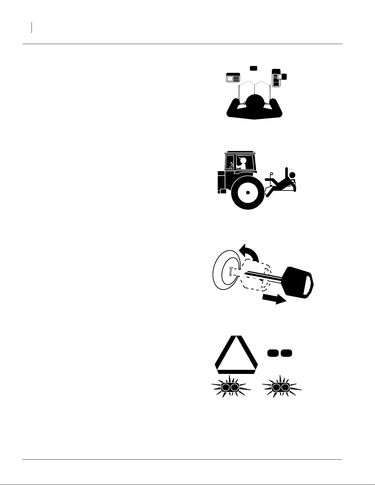
Be Familiar with Safety Decals
▲ Read and understand “Safety Decals,”page 7,
thoroughly.
▲ Read all instructions noted on the decals.
Keep Riders Off Machinery
Riders obstruct the operator’s view. Riders could
be struck by foreign objects or thro wn from the
machine.
▲ Never allow children to operate equipment.
▲ Keep all bystanders away from machine dur-
ing operation.
Shutdown and Storage
▲ Lower implement, put tractor in park, turn off
engine, and remove the key.
▲ Secure implement using blocks and supports
provided.
▲ Detach and store implement in an area where
children normally do not play.
Use Safety Lights and Devices
Slow-moving tractors and towed implements can
create a hazard when driven on public roads.
They are difficult to see, especially at night.
▲ Use flashing warning lights and turn signals
whenever driving on public roads.
▲ Use lights and devices provided with imple-
ment.
OFF
596-098M
8/6/07
Page 5

Transport Machinery Safely
Maximum transport speed for implement is 20
mph. Some rough terrains require a slower
speed. Sudden braking can cause a towed load to
swerve and upset.
▲ Do not exceed 20 mph. Never travel at a
speed which does not allow adequate control
of steering and stopping. Reduce speed if
towed load is not equipped with brakes.
▲ Comply with state and local laws.
▲ Do not tow an implement that, when fully
loaded, weighs more than 1.5 times the weight
of towing vehicle.
▲ Carry reflectors or flags to mark implement in
case of breakdown on the road.
▲ Keep clear of overhead power lines and other
obstructions when transporting.
Important Safety Information
3
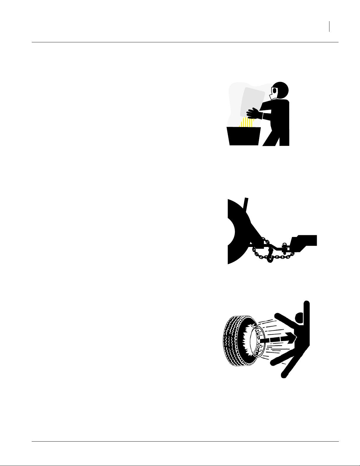
Avoid High Pressure Fluids
Escaping fluid under pressure can penetrate the
skin, causing serious injury.
▲ Avoid the hazard by relieving pressure before
disconnecting hydraulic lines.
▲ Use a piece of paper or cardboard, NOT
BODY PARTS, to check for suspected leaks.
▲ Wear protective gloves and safety glasses or
goggles when working with hydraulic systems.
▲ If an accident occurs, see a doctor immedi-
ately. Any fluid injected into the skin must be
surgically removed within a few hours or gangrene may result.
8/6/07
596-098M
Page 6

5, 7, & 9 Shank
4
Practice Safe Maintenance
▲ Understand procedure before doing work. Use
proper tools and equipment. Refer to this manual for additional information.
▲ Work in a clean, dry area.
▲ Lower the implement, put tractor in park, turn
off engine, and remove key before performing
maintenance.
▲ Make sure all moving parts have stopped and
all system pressure is relieved.
▲ Allow implement to cool completely.
▲ Disconnect battery ground cable (-) before
servicing or adjusting electrical systems or
before welding on implement.
▲ Inspect all parts. Make sure parts are in good
condition and installed properly.
▲ Remove buildup of grease, oil or debris.
▲ Remove all tools and unused parts from
implement before operation.
Prepare for Emergencies
▲ Be prepared if a fire starts.
▲ Keep a first aid kit and fire extinguisher handy.
OFF
▲ Keep emergency numbers for doctor, ambu-
lance, hospital and fire department near
phone.
Wear Pr otective Equipment
▲ Wear protective clothing and equipment.
▲ Wear clothing and equipment appropriate for
the job. Avoid loose-fitting clothing.
▲ Because prolonged exposure to loud noise
can cause hearing impairment or hearing loss,
wear suitable hearing protection such as earmuffs or earplugs.
▲ Because operating equipment safely requires
your full attention, avoid wearing radio headphones while operating machinery.
911
596-098M
8/6/07
Page 7
Handle Chemicals Properly
Agricultural chemicals can be dangerous. Improper use can seriously injure persons, animals,
plants, soil and property .
▲ Read and follow chemical manufacturer’s
instructions.
▲ Wear protective clothing.
▲ Handle all chemicals with care.
▲ Avoid inhaling smoke from any type of chemi-
cal fire.
▲ Store or dispose of unused chemicals as
specified by chemical manufacturer.
Use A Safety Chain
▲ Use a safety chain to help control drawn
machinery should it separate from tractor
drawbar.
Important Safety Information
5
▲ Use a chain with a strength rating equal to or
greater than the gross weight of towed
machinery.
▲ Attach chain to tractor drawbar support or
other specified anchor location. Allow only
enough slack in chain to permit turning.
▲ Replace chain if any links or end fittings are
broken, stretched or damaged.
▲ Do not use safety chain for towing.
Tire Safety
Tire changing can be dangerous and should be
performed by trained personnel using correct
tools and equipment.
▲ When inflating tires, use a clip-on chuck and
extension hose long enough for you to stand
to one side–not in front of or over tire assembly. Use a safety cage if available.
▲ When removing and installing wheels, use
wheel-handling equipment adequate for
weight involved.
8/6/07
596-098M
Page 8

5, 7, & 9 Shank
6
Safety at All Times
Thoroughly read and understand the instructions
in this manual before operation. Read all instructions noted on the safety decals.
▲ Be familiar with all implement functions.
▲ Operate machinery from the driver’s seat only.
▲ Do not leave implement unattended with trac-
tor engine running.
▲ Do not dismount a moving tractor. Dismount-
ing a moving tractor could cause serious injury
or death.
▲ Do not stand between the tractor and imple-
ment during hitching.
▲ Keep hands, feet and clothing away from
power-driven parts.
▲ Wear snug-fitting clothing to avoid entangle-
ment with moving parts.
▲ Watch out for wires, trees, etc., raising imple-
ment. Make sure all persons are clear of working area.
▲ Do not turn tractor too tightly, causing imple-
ment to ride up on wheels. This could cause
personal injury or equipment damage.
596-098M
8/6/07
Page 9
Important Safety Information
7
Safety Decals
Your implement comes equipped with all safety
decals in place. They were designed to help you
safely operate your implement.
▲ Read and follow decal directions.
▲ Keep all safety decals clean and legible.
▲ Replace all damaged or missing decals. Order
new decals from your Great Plains dealer.
Refer to this section for proper decal placement.
▲ When ordering new parts or components, also
request corresponding safety decals.
▲ To install new decals:
1. Clean the area on which the decal is to be
placed.
2. Peel bac king from decal. Press firmly on
surface, being careful not to cause air
bubbles under decal.
818-055C
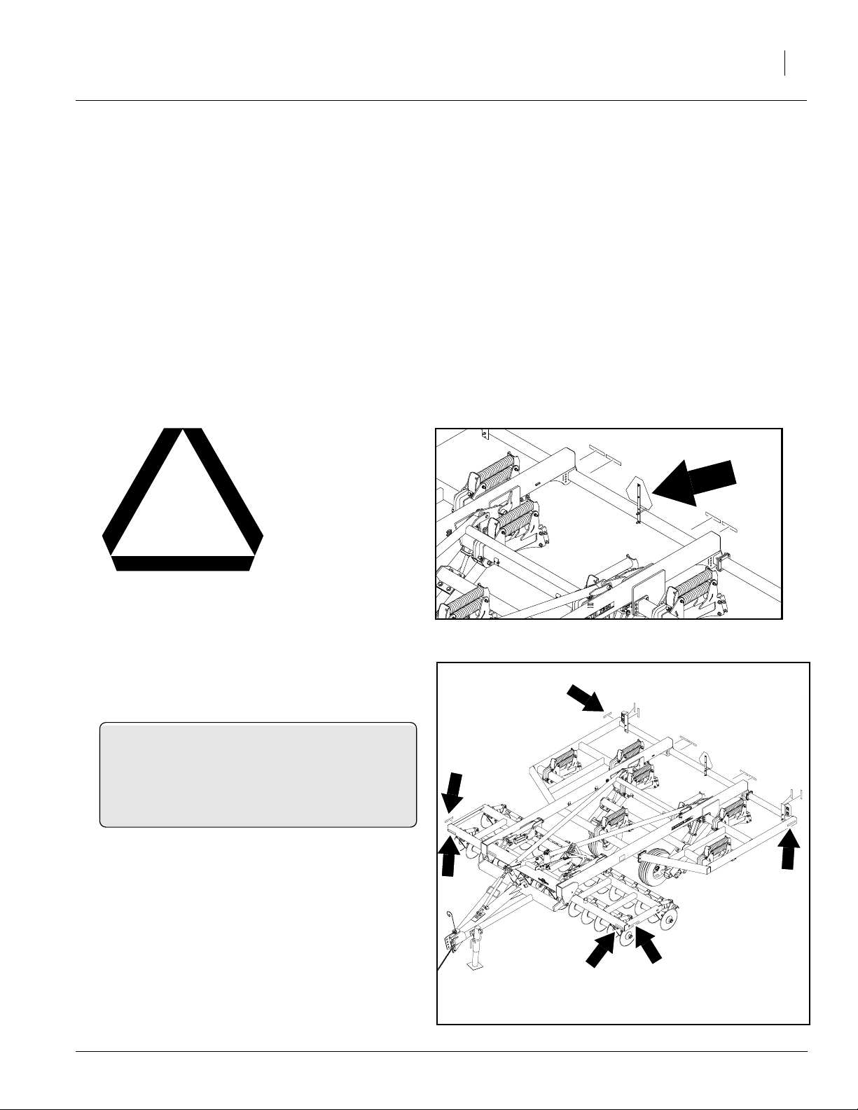
Slow Moving Vehicle Label
838-265C
Amber Reflectors
Reflector located on outside edges front and rear,
outside edges on front frame, left of center on front
frame; 6 reflectors total
21574
8/6/07
21574
596-098M
Page 10
5, 7, & 9 Shank
8
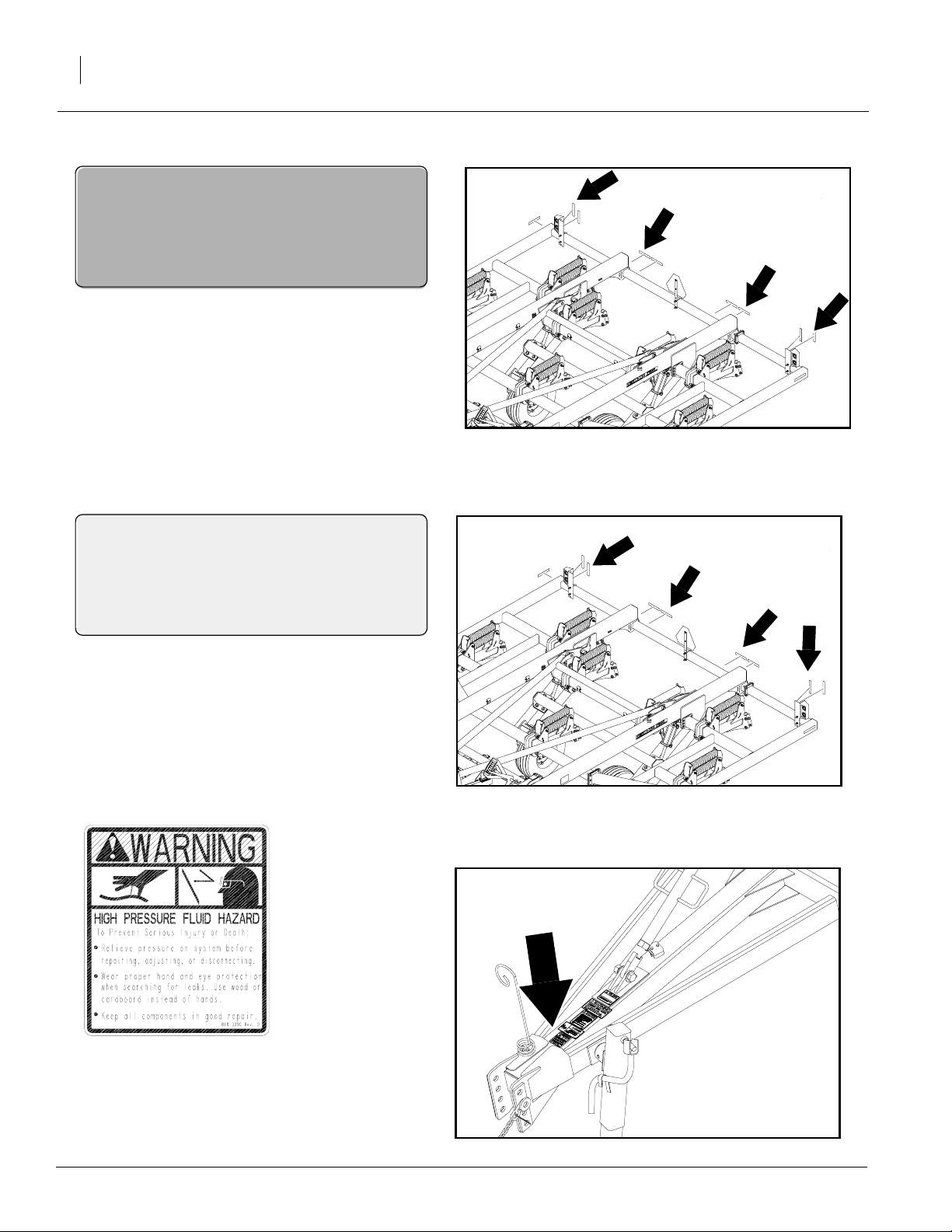
838-266C
Red Reflectors
Reflector located on both ends and center left and
right on rear; 4 reflectors total
21574
838-267C
Daytime Reflectors
Reflector located on both ends and center left and
right on rear; 4 reflectors total
818-339C
Warning, High Pressure Fluid Hazard
One decal located on tongue
21574
21612
596-098M
8/6/07
Page 11
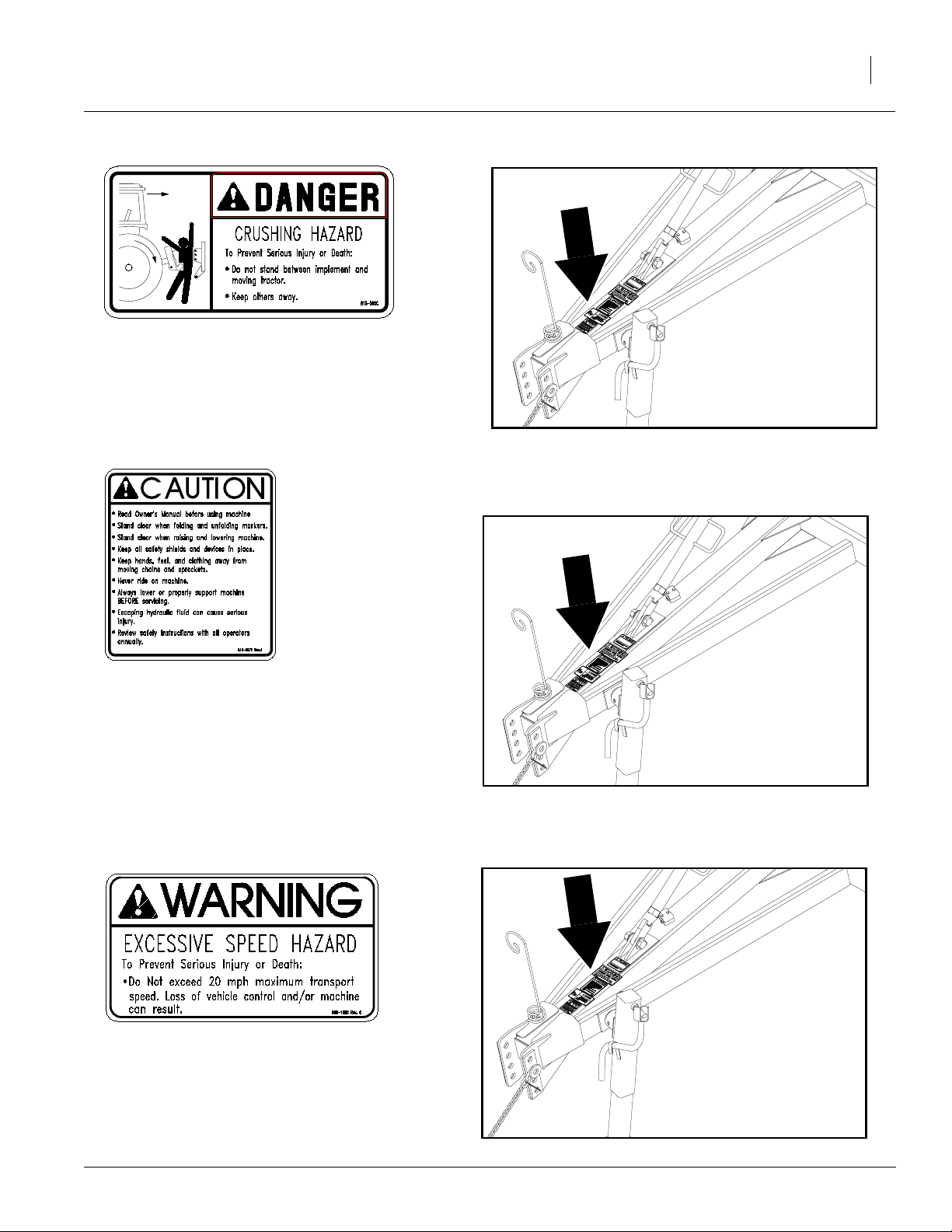
818-590C
Danger, Crushing Hazard
One decal located on tongue
Important Safety Information
21612
9
818-587C
Caution, Operational Machine
One decal located on tongue
818-188C
Warning, Excessive Speed Hazard
One decal located on tongue
21612
21612
8/6/07
596-098M
Page 12
5, 7, & 9 Shank
10
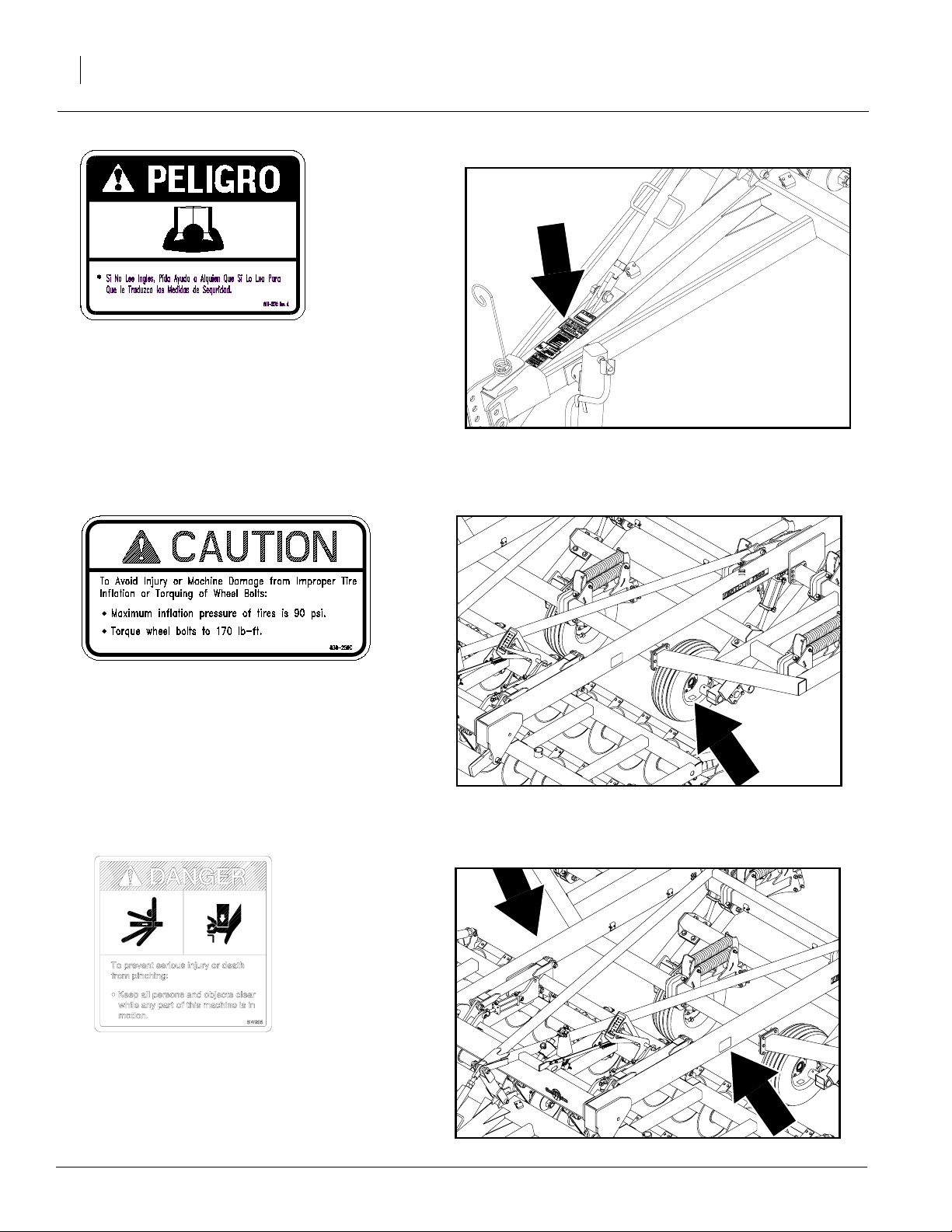
818-557C
Danger, Cannot Read English
One decal located on tongue
21612
838-259C
Caution, Tire Pressure
Decal located on all wheels; 4 decals total
838-112C
Danger, Pinching Hazard
Decal located on both sides of the frame; 2 decals
total
21574
21574
596-098M
8/6/07
Page 13

Introduction
Great Plains welcomes you to its growing f amily of
new product owners. This implement has been
designed with care and built by skilled workers using quality materials. Proper setup, maintenance
and safe operating practices will help y ou get
years of satisfactory use from the machine.
Description of Unit
The V erti-Till Ripper is designed to cut and size
residue, till soil for f aster seedbed warming, break
up soil crust on hard dried fields while eliminating
compaction layers.
Models Covered
VT 5300, VT 7225, VT 7300 and VT 9225 V ertiTill Rippers.
Introduction
11
Using This Manual
This manual will familiarize you with safety, assembly, operation, adjustments, troubleshooting
and maintenance. Read this manual and follo w
the recommendations to help ensure safe and efficient operation.
The information in this manual is current at printing. Some parts may change to assure top
performance.
Definitions
The following terms are used throughout this
manual.
Right-hand and left-hand as used in this manual
are determined by facing the direction the machine will travel while in use unless otherwise
stated.
IMPORTANT: A crucial point of information related to the preceding topic. For safe and correct operation, read and follow the directions
provided before continuing.
21569
NOTE: Useful inf ormation related to the preceding topic.
8/6/07
596-098M
Page 14

5, 7, & 9 Shank
12
Owner Assistance
If you need customer service or repair parts, contact a Great Plains dealer. The y ha ve trained
personnel, repair parts and equipment specially
designed for Great Plains products.
Y our machine’ s parts were specially designed and
should only be replaced with Great Plains parts.
Always use the serial and model number when ordering parts from your Great Plains dealer.
Record your implement model and serial number
here for quick ref erence:
Model Number:__________________________
Serial Number: ___________________________
Your Great Plains dealer wants you to be satisfied
with your new machine. If y ou do not understand
any part of this manual or are not satisfied with the
service received, please take the following
actions.
1. Discuss the matter with your dealership service manager. Mak e sure they are a w are of
any problems so they can assist y ou.
2. If you are still unsatisfied, seek out the owner
or general manager of the dealership.
3. For further assistance write to:
Product Support
Great Plains Mfg. Inc., Service Department
PO Box 5060
Salina, KS 67402-5060
596-098M
8/6/07
Page 15

Preparation and Setup
This section will help you prepare your tractor and
implement for use. Bef ore going to the field, you
must hitch a tractor to the implement, hook up hydraulics and check that hydr aulics ha ve been
bled.
Prestart Checklist
1. Read and understand “Important Safety Information,” page 1.
2. Check that all working parts are moving freely, bolts are tight, and cotter pins are spread.
3. Check that all grease fittings are in place and
lubricated. Refer to “Lubrication,” page 33.
Preparation and Setup
13
4. Check that all saf ety decals and reflectors are
correctly located and legible. Replace if damaged. See “Safety Decals,” page 7.
5. Inflate tires to pressure recommended and
tighten wheel bolts as specified. See “Appendix,” page 35.
Hitching Tractor to Implement
!
DANGER
Y ou may be sever ely injur ed or killed by being crushed
between the tractor and implement. Do not stand or
place any part of your body between implement and
moving tractor. Stop tractor engine and set park brake
before installing the hitch pin.
Hitch Height
For proper operation, the main frame of the VertiTill should be level in the field. A turnbuc kle between the tongue and level linkage is used to le vel
the V erti-Till.
Refer to Figure 1
1. For most hitch heights the hitch should be installed inverted using the middle two bolts
holes. If the tractor hitch height is extremely
high or low , and the turnbuc kle will not allo w
the frame to be leveled, the hitch can be
moved up or down in the holes pro vided. The
hitch can also be flipped over f or more adjustment.
Turnbuckle
21649
Hitch in normal
position
Figure 1
Turnbuckle and Hitch
8/6/07
596-098M
Page 16

5, 7, & 9 Shank
14
Hitching to Tractor
1. Back tractor to implement. Use the scre w jack
to adjust the hitch up or down as needed.
2. Finish backing the tractor until the hitch pin
holes align. Place the tractor in park and pin
the implement to the tractor using the tractor’ s
original equipment hitch pin as outlined in the
tractor’s oper ator manual.
3. Securely attach the implement’ s saf ety chain
to the tractor as outlined in the tractor’ s operator manual.
4. Connect the light harness and plug in the hydraulic hoses. (See Hydraulic Hose Hookup
below).
Refer to Figure 2
5. Lower the jack until the full w eight of the implement is on the tractor drawbar. Remove
the jack from the side of the tongue and store
it on the storage stob located on the top lefthand side of the coulter frame.
21650
Figure 2
Jack in Storage Position
Hydraulic Hose Hookup
Refer to Figure 3
Great Plains hydraulic hoses have color coded
handles to help you hook up hoses to your tractor
outlets. Hoses that go to the same remote valve
are marked with the same color.
Color Hydraulic Function
Black Transport Lift Cylinders
Red Coulter Cylinders
Yellow Seedbed Conditioner
One plastic grip in each color shows a retracting
cylinder and the other shows an extending
cylinder.
22570
Figure 3
Hydraulic Hose Label
596-098M
8/6/07
Page 17

Bleeding Hydraulics
!
WARNING
Escaping fluid under pressur e can have sufficient pr essure to penetrate the skin. Check all hydraulic lines
and fittings before applying pressure. Fluid escaping
from a very small hole can be almost in visible. Use paper or cardboard, not body parts, and wear heavy
gloves to check for suspected leaks. If injured, seek
medical assistance from a doctor that is familiar with
this type of injury. Foreign fluids in the tissue must be
surgically removed within a few hours or gangrene
will result.
If the implement is being hooked to a tractor for the
first time, the hydraulic system ma y ha v e to be
purged of air.
Preparation and Setup
15
1. Check the h ydraulic fluid in the tr actor reservoir and fill to proper lev el.
Bleeding T ransport Cylinders
2. Back the paddle aw ay from the hydraulic
depth control valve on the implement.
3. With the transport locks installed on the transport cylinders, see “Transporting, ” page 30,
crack open the JIC fittings on the rod ends.
Engage the hydraulics to “lower” the implement until fluid escapes from the loose fittings. Tighten these two fittings.
4. Raise the implement and remove the tr ansport locks. Lower the implement completely.
5. Crack open the JIC fittings on the base end of
the transport cylinders. Engage the hydraulics to “raise” the implement until fluid escapes from the loose fittings. Tighten these
fittings.
6. Raise and lower the implement se ver al times
to ensure smooth operation. If the unit raises
unevenly or is not smooth, y ou may have to
repeat the bleeding procedure.
Bleeding Coulter Cylinders
1. Start with the implement fully raised to allow
for a full range of coulter frame movement.
2. Lower the coulter frame . Crack the fittings on
the base end of the coulter cylinders. Engage
the hydraulics to “raise” the coulters until fluid
escapes from the loose fittings. Tighten these
fittings.
8/6/07
3. Raise the coulter frame and bloc k it in place
so it cannot lower . Crack the fittings on the rod
end of the coulter cylinders. Engage the hydraulics to “lower” the coulters until fluid escapes from the loose fittings. Tighten these
fittings.
596-098M
Page 18

5, 7, & 9 Shank
16
Mounting Wheels
Refer to Figure 4
1. Mount the outside wheels (1) to the wheel
arms (2) by inserting the spindle pin in the
rear mounting bracket.
2. Secure pin in place with a 5/16” x 4” bolt and
5/16” lock nut.
596-098M
21580
Figure 4
Mounting Wheels
8/6/07
Page 19

Mounting Coulter Gangframe
Refer to Figure 5
1. Slide the coulter gangframe (1) under the
front end of the V erti-Till Ripper . Make sure
the coulters angle towards the back of the ripper.
2. P osition the coulter gangframe (1) so the four
lifting brackets are directly below the four
brackets on the front and rear coulter gangframe rockshaft.
3. Using the hydraulics of the implement, r aise
or lower the coulter and/or transport cylinders. Align the holes in the coulter frame with
the coulter lift arms.
4. Insert pins (2) aligning holes in the ends of the
pins with the holes in the brackets. Secure
pins with 3/8” x 2 1/2” bolts and 3/8” lock nuts.
Preparation and Setup
17
8/6/07
21581
Figure 5
Mounting Coulter Gangframe
596-098M
Page 20

5, 7, & 9 Shank
18
Mounting Wings
Refer to Figure 6
1. Attach the right-hand (1) and left-hand (2)
wings to the main frame using 5/8” x 2 1/4”
bolts, 5/8” lock washers and 5/8” nuts .
596-098M
21582
Figure 6
Mounting Wings
8/6/07
Page 21

Shank Mounting
Straight and Parabolic Shanks
Refer to Figure 7
1. Attach the straight shank (shown) (1) to the auto
reset shank mount (shown) (2) using 3/4” x 6”
GRD8 bolts (3), 3/4” hardened flat washers (4),
3/4” lock washers (5) and 3/4” nuts (6).
2. Place two flat washers (4) against the head of the
bolt (3) and one flat washer (4) next to the lock
washer (5).
NOTE: Extra hardened washers allo ws use of longer
bolt to keep threads out of the shear area.
3.
Torque bolts (3) to 400 FT LBS.
IMPORTANT: Torque bolts (3) to 400 FT LBS.
Preparation and Setup
19
Note: The parabolic shank and the rigid shank mount
will use same hardware and instructions.
8/6/07
22741
Figure 7
Shank Mounting
596-098M
Page 22

5, 7, & 9 Shank
20
Shank Mounting
No-Till Shanks
Refer to Figure 8
1. Attach the no-till shank (shown) (1) to the auto reset shank mount (shown) (2) using 3/4” x 6”
GRD8 bolts (3), 3/4” hardened flat washers (4),
3/4” lock washers (5) and 3/4” nuts (6).
2. Place two flat washers (4) against the head of the
bolt (3) and one flat washer (4) next to the lock
washer (5).
NOTE: Extra hardened washers allo ws use of longer
bolt to keep threads out of the shear area.
3. Torque bolts (3) to 400 FT LBS.
IMPORTANT: Torque bolts (3) to 400 FT LBS.
Note: Mounting to the rigid shank mount will use same
hardware and instructions.
596-098M
22740
Figure 8
No-Till Shank Mounting
8/6/07
Page 23

Installing Shins and Tips
Straight and Parabolic Shanks
Refer to Figure 9
1. Attach straight shin retainer (shown) (1) to the
straight shank using 1/2 x 2 1/2” bolts and 1/2”
lock nuts.
2. Slide one end of the straight shin (shown) (2)
under the shin retainer (1). Hold the lower end
in place by installing a tip (1 1/4” x 2” with fin
shown) (3). Use 1/2” x 2 1/2” bolts and 1/2”
flange lock nuts to secure tip.
Note: The the retainers and shins for the parabolic
shank and rigid shank mount use the same hardware.
Preparation and Setup
21
8/6/07
21603
Figure 9
Shims and Tips
596-098M
Page 24

5, 7, & 9 Shank
22
Installing Shins and Tips
No-Till Shanks
Refer to Figure 10
1. Attach the no-till shin retainer (1) to the no-till
shank using 1/2” x 1 3/4” bolts, 1/2” lock
washers and 1/2” nuts.
2. Remove the 1/2” x 1 3/4” roll pin (2) and sa ve
for later use.
3. Slide one end of the no-till shin (3) under the
no-till shin retainer (1). Hold the lower end in
place by installing a no-till tip (4). Secure the
no-till tip in place with the roll pin (2) removed
in step 2.
4. Insert larger roll pin (5) through second hole
in the no-till tip (4) to help secure tip.
596-098M
21655
Figure 10
No-Till Shins and Tips
8/6/07
Page 25

Machine Adjustments
Auto Reset Shanks
Refer to Figure 11
1. The dual spring package should be preloaded so
both top and bottom springs are loaded evenly
and measure 20.75 inches (for machines with S/
N 1054mm-) and 23.8 inches (for machines with
S/N 1055mm+) from end of coil to end of coil.
The bottom of the shank arm will just touch the
down stop on the shank mount when the springs
are at the correct preload.
24464
Preparation and Setup
S/N 1055mm +
Down Stop
(not visible)
S/N 1054mm -
23
Coulter Gang Springs
Refer to Figure 12
2. The coulter gangs are cushioned with a preloaded coil spring. The nut near the bottom trunnion
should be adjusted so the spring assembly measures 14 1/2” from inside of upper washer to inside of lower washer.
8/6/07
21657
Down Stop
(not visible)
Figure 11
Auto Reset Shanks
21658
Figure 12
Coulter Gang Springs
596-098M
Page 26

5, 7, & 9 Shank
24
This section covers general operating procedures. Experience, machine familiarity and the
following inf ormation will lead to efficient operation and good working habits. Always operate
farm machinery with safety in mind.
Prestart Checklist
Escaping fluid under pressur e can have sufficient pr essure to penetrate the skin. Check all hydraulic lines
and fittings before applying pressure. Fluid escaping
from a very small hole can be almost in visible. Use paper or cardboard, not body parts, and wear heavy
gloves to check for suspected leaks. If injured, seek
medical assistance from a doctor that is familiar with
this type of injury. Foreign fluids in the tissue must be
surgically removed within a few hours or gangrene
will result.
Operating Instructions
!
WARNING
1. Carefully read “Important Safety Information, ”
page 1.
2. Lubricate implement as indicated under “Lubrication,” page 33.
3. Check all tires f or proper inflation. See “Appendix,” page 35.
4. Check all bolts, pins and f asteners. Torque as
shown in “Appendix,” page 35.
5. Check implement f or worn or damaged parts.
Repair or replace parts before going to the
field.
6. Check h ydraulic hoses, fittings and cylinders
for leaks. Repair or replace bef ore going to
the field.
596-098M
8/6/07
Page 27

Field Operation
Operating Instructions
25
!
DANGER
Y ou may be sever ely injur ed or killed by being crushed
between the tractor and implement. Do not stand or
place any part of your body between implement and
moving tractor. Stop tractor engine and set park brake
before installing hitch pin.
The leveling links and depth indicator linkages f or
both the tillage depth and coulter depth are interactive. Each step in these field adjustments relies
on the previous step being done correctly. Complete the following steps in the order listed.
Leveling the Implement
1. While pulling forward in a le vel field, lo wer the
V erti-Till to a depth of around 8” to 10”. The
depth you choose is not critical at this point.
Refer to Figure 13
2. Stop the tractor with the Verti-Till in the
ground and check the frame f or level. The two
main frame tubes running the length of the
unit should be parallel to the ground.
a. If the frame is high in front, loosen the jam
nut and shorten the turnbuckle on the
tongue. Secure the jam nut.
b. If the frame is low in front, loosen the jam
nut and lengthen the turnbuckle on the
tongue. Secure the jam nut.
Note: Repeat step 2 as needed until implement is
level.
Setting the Tillage Depth Indicator Gage
1. Pull the Verti-Till forward in the field and fully
lower the unit (16”). In hard conditions you
may hav e to till a small area twice to be able to
pull the unit at full depth.
Turnbuckle
21649
Figure 13
Turnbuckle
Depth
Pointer
Refer to Figure 14
2. Stop the tractor and from the tractor seat observe where the tillage depth pointer is pointing. With the unit fully lowered the depth
indicator should read 16.
8/6/07
21659
Figure 14
Tillage Depth Indicator
596-098M
Page 28

5, 7, & 9 Shank
26
Refer to Figure 15
3. To adjust this reading, loosen the two bolts
joining the tip depth link and lengthen or shorten as needed. Retighten and check the setting
from the tractor seat.
Note: The tip depth link has two notches that can
be aligned with each other and used as a starting
point when adjusting the length of this link.
Once set, the tip depth indicator will show actual
tip depth and is very accurate through a range of 6”
to 16”.
Before moving on to the ne xt step , the unit can be
raised from the full 16” depth. The depth you chose
in not critical, but should be at least 6” deep.
Setting the Coulter Depth Indicator Gage
1. Adjust the cutting depth of the coulters to
about 2” or 3” while traveling through the field.
Stop the tractor and dig to find the bottom of
several coulters . Measure or estimate an average cutting depth.
21660
Figure 15
Tip Depth Pointer Linkage
Depth
Pointer
Refer to Figure 16
2. Observe from the tractor seat the coulter
depth pointer. Adjust the coulter depth linkage
until the indicator reads the same depth you
averaged in step 1 abo ve.
Refer to Figure 17
3. To adjust the coulter depth pointer, loosen the
two bolts joining the coulter depth link and
lengthen or shorten as needed. Retighten and
check the setting from the tractor seat.
Note: The coulter depth link has two notches that
can be aligned with each other and used as a starting point when adjusting the length of this link.
Once set, the coulter depth indicator will show actual coulter depth and is very accurate through a
range of 1” to 4”.
Note: As the coulter blades wear you will not be
cutting the same depth as with a new 20” blade.
The coulter depth linkage can be adjusted periodically as the blade wears so it will continue to report an accurate cutting depth.
21659
Figure 16
Coulter Depth Indicator
596-098M
21661
Figure 17
Coulter Depth Pointer Linkage
8/6/07
Page 29

Normal Field Operations
For drills with S/N: 1025MM and below.
Refer to Figure 18
1. Lower the frame to a desired tillage depth. The
depth control paddle can be pushed up against
the depth control valve stem and loc k ed with
the knob. The unit will automatically stop at this
depth each time the unit is lowered.
For drills with S/N: 1026MM and above.
Refer to Figure 19
Knob
Operating Instructions
Paddle
Valve Stem
Figure 18
Depth Control Paddle
27
21660
1. Raise the implement fully and install the cylinder locks, see “Lock Cylinders ,” page 28. Pull
the spring loaded pin (1) and slide the moveable depth stop (2) to achiev e desired tillage
height and re-engage pin. The top hole allows
for a 16” tilling depth and the lower hole allo ws
for a 6” tilling depth. Repeat for opposite wheel
arm.
NOTE: Be sure the lock pins are set in the same
holes on both wheel arms.
2. Adjust the coulters up or down to achieve different tilling, cutting and mixing results. A pilot
operated check valv e in the coulter lift circuit
will lock the coulters at the depth you choose.
3. Always lift the unit out of the g round when turning at field ends and other short radius turns to
avoid damage and premature wear to the
shanks and coulter gangs.
4. Both the Auto reset and Rigid shank mounts
are protected by shear bolts for e xtreme overloads. If the shank bolt shears replace the lower bolt with the correct shear bolt, use GP part
number 802-060C. (HHCS 5/8-11 x 4 Gr5)
Note: For your con venience a series of holes in 4
gussets on the rear of the machine have been provided for spare shear bolt storage.
22563
Deep
16”
Frame
Bumper
w
Shallo
6”
Figure 19
Manual Depth Stop
8/6/07
596-098M
Page 30

5, 7, & 9 Shank
28
Transporting
!
WARNING
T owing the implement at high speeds or with a vehicle
that is not heavy enough could lead to loss of vehicle
control. Loss of vehicle control could lead to serious
road accidents, injury and death. T o r educe the hazard,
do not exceed 20 mph. Check that your tractor has
enough ballast to handle the weight of the implement.
Refer to your tractor operator’ s manual for ballast requirements.
!
CAUTION
Failure of hydraulic cylinders during transport will
cause implement to drop suddenly , which could lead to
serious road accidents, injury or death. To prevent an
accident, always install cylinder locks before transporting implement.
Before transporting the implement, follow and
check these items:
Refer to Figure 20
Lock Cylinders. Cylinder locks are supplied for
both hydraulic transport cylinders. With implement fully raised, position lock channel ov er rod of
cylinder and secure into place with the pin and
spring clip.
NOTE: The cylinder locks can only be installed or
removed after the implement is fully raised.
When cylinder locks are not being used they can
be stored on the storage tubes located on the underside of the main frame directly above each
wheel.
Clearance. Remember that the implement is wider that the tractor. Allo w safe clearance.
Road rules. Comply with all federal, state and local safety laws when tra veling on public roads.
21621
Figure 20
Transport Locks
596-098M
8/6/07
Page 31

Parking
Perf orm the f ollo wing steps when parking the implement. Refer to “Storage”, page 32, to prepare
for long-term storage.
1. Park implement on a le vel, solid area.
2. Lower implement until the weight is resting on
the transport lock channels or remove and
store the transport lock channels then lower
the implement until the shanks are resting on
the ground.
3. Securely block tires to prevent rolling.
4. Remove tongue jac k from stor age stob. Pin
jack on side of tongue. If ground is soft, place
a board or plate under jack.
5. Extend jack until tongue weight is off tractor
drawbar.
Operating Instructions
29
6. Unplug hydraulic hoses and wiring harness
from tractor. Do not allo w hose ends or harness ends to rest on the ground.
7. Remove hitch bolt and saf ety chain from tractor drawbar .
8/6/07
596-098M
Page 32

5, 7, & 9 Shank
30
Troubleshooting
Problem Cause Solution
Tip depth changes
Coulter depth changes
Coulter gangs uneven
Ripper point depths uneven
Shear bolts shear too often
Leaking hydraulic cylinders (external or internal).
Failing depth stop valve. Install seal kit or replace depth stop
Leaking hydraulic fittings. Check fittings for leaks, see page
Leaking hydraulic cylinders (external or internal).
Failing P.O. check valve. Install seal kit or replace check
Install seal kit or replace cylinder.
valve.
15 for safety message, tighten or
replace.
Install seal kit or replace cylinder.
valve.
Check/adjust preload on gang
springs.
Re-level the implement.
Check/adjust preload on auto reset
shank.
Re-level the implement.
Check tire pressure.
Check depth stops for even.
Order the auto reset shank mount
in rocky conditions.
Depth pointers not accurate
596-098M
Level unit and re-zero pointers.
Check shank spring preload.
Check coulter blade wear.
8/6/07
Page 33

Maintenance and Lubrication
Maintenance
Proper servicing and maintenance is the key to long
implement life. With careful and systematic inspection, you can avoid costly maintenance , downtime
and repair.
Always turn off and remove the tr actor k ey before
making any adjustments or performing any
maintenance.
!
WARNING
You may be severely injured or killed by being crushed
under the falling implement. Always have transport
locks in place and frame sufficiently blocked up when
working on implement.
Maintenance and Lubrication
OFF
31
!
WARNING
Escaping fluid under pressure can have sufficient pressure to penetrate the skin. Chec k all hydr aulic lines and
fittings before applying pressure. Fluid escaping from a
very small hole can be almost invisible. Use paper or
cardboard, not body parts, and wear heavy gloves to
check for suspected leaks. If injur ed, seek medical assistance from a doctor that is familiar with this type of injury. Foreign fluids in the tissue must be surgically
removed within a few hours or gangrene will result.
Refer to Figure 21
1. After using the implement for se veral hours,
check all bolts to be sure they are tight.
2. After one hour and again after five hours retorque the grade 8 bolts (1) to 400 FT LBS. Retorque periodically.
3. After one hour and again after five hours retorque the grade 8 clamp bolts (2) to 400 FT
LBS. Re-torque periodically.
4. Lubricate areas listed under “Lubrication”, page
33.
5. Inflate tires as specified on “Tire Inflation
Chart”, page 35.
8/6/07
Figure 21
Re-torque Bolts
22742
596-098M
Page 34

5, 7, & 9 Shank
32
6. Replace any worn, damaged or illegible saf e-
7. To increase seal and bearing life, the taper
8. To increase seal and bearing life, the taper
ty decals. Order new decals from your Great
Plains dealer. See “Saf ety Decals”, page 7.
roller bearings in all 4 transport wheels
should be checked f or play at least once a
season. Lower the unit so the shanks contact
the ground. Retract the transport cylinders
until the transport wheels are off the ground.
Rock each wheel side to side to check f or
play. Remove the dust cap and remove pla y
with the slotted nut as needed.
roller bearings in the walking tandems should
be checked in a similar manner . Each walking
tandem has a slotted nut which can be used
to remove pla y. There is no dust cap to remove. The nut is visible from the outside.
Storage
Store implement where children do not play. If
possible, store the drill inside for longer lif e.
1. Remove an y dirt and debris that can hold
moisture and cause corrosion.
2. Lubricate areas noted under “Lubrication”,
page 33.
3. Inspect implement for worn or damaged
parts. Make repairs and service during the off
season.
4. Use spray paint to co ver scratches, chips and
worn areas on the implement to protect the
metal.
5. Retract the hydr aulic cylinders so the plated
rod is inside the barrel to minimize rust.
596-098M
8/6/07
Page 35

Lubrication
Maintenance and Lubrication
33
Multipurpose
spray lube
Shank Pivot Arms
Type of Lubrication: Grease
Quantity = Until grease emerges
Seasonally
50
Multipurpose
grease lube
Multipurpose
oil lube
50
Intervals at which
lubrication is required
21618
Wheel Bearings
Type of Lubrication: Grease
Quantity = Repack
Rockshaft Pivot
Type of Lubrication: Grease
Quantity = Until grease emerges
21619
10
21620
8/6/07
596-098M
Page 36

5, 7, & 9 Shank
34
Gang Bearings
Type of Lubrication: Grease
Quantity = Until grease emerges
50
10
21663
21618
Lift Link Bearings
Type of Lubrication: Grease
Quantity = Until grease emerges
Seasonally
Walking Tandem Bearings
Type of Lubrication: Grease
Quantity = Repack
21664
21665
596-098M
8/6/07
Page 37

Appendix
Torque Values Chart
Bolt Head Identification
Bolt Head Identification
Appendix
35
Bolt Size
(Inches)
1
in-tpi
1/4" - 20 7.4 5.6 11 8 16 12 M 5 X 0.8 4 3 6 5 9 7
1/4" - 28 8.5 6 13 10 18 14 M 6 X 1 7 5 11 8 15 11
5/16 - 18 15 11 24 17 33 25 M 8 X 1.25 17 12 26 19 36 27
5/16" - 24 17 13 26 19 37 27 M 8 X 1 18 13 28 21 39 29
3/8" - 16 27 20 42 31 59 44 M10 X 1.5 33 24 52 39 72 53
3/8" - 24 31 22 47 35 67 49 M10 X 0.75 39 29 61 45 85 62
7/16" - 14 43 32 67 49 95 70 M12 X 1.75 58 42 91 67 125 93
7/16" - 20 49 36 75 55 105 78 M12 X 1.5 60 44 95 70 130 97
1/2" - 13 66 49 105 76 145 105 M12 X 1 90 66 105 77 145 105
1/2" - 20 75 55 115 85 165 120 M14 X 2 92 68 145 105 200 150
9/16" - 12 95 70 150 110 210 155 M14 X 1.5 99 73 155 115 215 160
9/16" - 18 105 79 165 120 235 170 M16 X 2 145 105 225 165 315 230
5/8" - 11 130 97 205 150 285 210 M16 X 1.5 155 115 240 180 335 245
5/8" - 18 150 110 230 170 325 240 M18 X 2.5 195 145 310 230 405 300
3/4" - 10 235 170 360 265 510 375 M18 X 1.5 220 165 350 260 485 355
3/4" - 16 260 190 405 295 570 420 M20 X 2.5 280 205 440 325 610 450
7/8" - 9 225 165 585 430 820 605 M20 X 1.5 310 230 650 480 900 665
7/8" - 14 250 185 640 475 905 670 M24 X 3 480 355 760 560 1050 780
1" - 8 340 250 875 645 1230 910 M24 X 2 525 390 830 610 1150 845
1" - 12 370 275 955 705 1350 995 M30 X 3.5 960 705 1510 1120 2100 1550
1-1/8" - 7 480 355 1080 795 1750 1290 M30 X 2 1060 785 1680 1240 2320 1710
1 1/8" - 12 540 395 1210 890 1960 1440 M36 X 3.5 1730 1270 2650 1950 3660 2700
1 1/4" - 7 680 500 1520 1120 2460 1820 M36 X 2 1880 1380 2960 2190 4100 3220
1 1/4" - 12 750 555 1680 1240 2730 2010
1 3/8" - 6 890 655 1990 1470 3230 2380
1 3/8" - 12 1010 745 2270 1670 3680 2710
1 1/2" - 6 1180 870 2640 1950 4290 3160
1 1/2" - 12 1330 980 2970 2190 4820 3560
Grade 2 Grade 5
N · m2ft-lb3N · m ft-lb N · m ft-lb mm x pitch4N · m ft-lb N · m ft-lb N · m ft-lb
Torque tolerance + 0%, -15% of torquing values. Unless otherwise specified use torque values listed above.
Grade 8
Bolt Size
(Metric)
1
in-tpi = nominal thread diameter in inches-threads per inch
4
mm x pitch = nominal thread diameter in millimeters x thread pitch
5.8 8.8 10.9
Class 5.8 Class 8.8 Class 10.9
2
N· m = newton-meters
3
ft-lb= foot pounds
Tire Inflation Chart
Tire Size Inflation
12.5L x 15” Load Range F . HYW Serv . 90
8/6/07
PSI
NOTE: All tires are warranted by the original manufacturer
of the tire. Tire warranty inf ormation can be found in the brochures included with your Operator’ s and P arts Manuals or
online at the manufacturer’s websites. For service assistance or information, contact your nearest Authorized F arm
Tire Retailer.
Manufacturer Website
Titan www.titan-inlt.com
Goodyear www.goodyearag.com
Firestone www.firestoneag.com
596-098M
Page 38

5, 7, & 9 Shank
36
Specifications and Capacities
Overall Height
Overall Length (no rear attachments)
Overall Width
Working Width
Shank Count and Spacing
Till Depth
Tires
Coulters
5300 7225 7300 9225
78” (6.5’)
314.25” (26.2’) 352.50” (29.4’) 314.25” (26.2’) 352.50” (29.4’)
155.75” (12.98’) 215.76” (17.98’)
12.5’ 17.5’
5 on 30” centers 7 on 22.5” centers 7 on 30” centers 9 on 22.5” centers
6” to 16”
12.5L 15 Load Range F on 8 bolt 10” rim
2” Turbo on 15” spacing (7.5” cutting width) 2 gangs
596-098M
8/6/07
Page 39

Hydraulic Schematics (for S/N: 1025MM and below)
Specifications and Capacities
37
8/6/07
21575
596-098M
Page 40

5, 7, & 9 Shank
38
Hydraulic Schematics (for S/N: 1026MM and abo ve)
596-098M
22564
8/6/07
Page 41

Specifications and Capacities
Warranty
Great Plains Manufacturing, Incorporated warrants to the original purchaser that this seeding equipment will be free from defects in material
and workmanship for a period of one year from the date of original purchase when used as intended and under normal service and conditions
for personal use; 90 days for commercial or rental purposes. This Warranty is limited to the replacement of any defective part by Great Plains
Manufacturing, Incorporated and the installation by the dealer of any
such replacement part. Great Plains reserves the right to inspect any
equipment or part which are claimed to have been defective in material
or workmanship.
This Warranty does not apply to any part or product which in Great
Plains’ judgement shall have been misused or damaged by accident or
lack of normal maintenance or care, or which has been repaired or altered in a way which adversely affects its performance or reliability, or
which has been used for a purpose for which the product is not designed. This Warranty shall not apply if the product is towed at a speed
in excess of 20 miles per hour.
Claims under this Warranty must be made to the dealer which originally
sold the product and all warranty adjustments must by made through
such dealer. Great Plains reserves the right to make changes in materials or design of the product at any time without notice.
This Warranty shall not be interpreted to render Great Plains liable for
damages of any kind, direct, consequential, or contingent, to property.
Furthermore, Great Plains shall not be liable for damages resulting from
any cause beyond its reasonable control. This Warranty does not extend to loss of crops, losses caused by harvest delays or any expense
or loss for labor, supplies, rental machinery or for any other reason.
No other warranty of any kind whatsoever, express or implied, is
made with respect to this sale; and all implied warranties of merchantability and fitness for a particular purpose which exceed
the obligations set forth in this written warranty are hereby disclaimed and excluded from this sale.
This Warranty is not valid unless registered with Great Plains Manufacturing, Incorporated within 10 days from the date of original purchase.
39
8/6/07
596-098M
Page 42

Great Plains Manufacturing, Inc.
Corporate Office: P.O. Box 5060
Salina, Kansas 67402-5060 USA
 Loading...