

Page 1
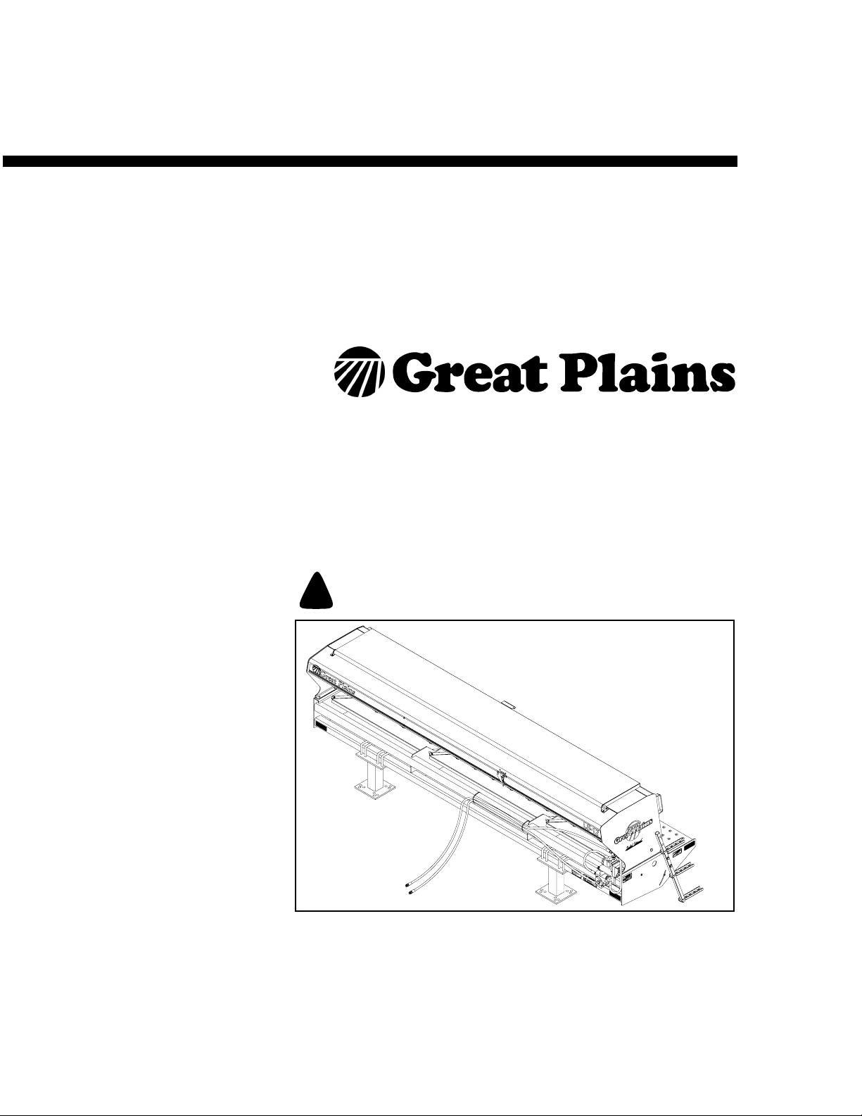
Operator’s Manual
LS10 and LS12
Levee Seeder
Manufacturing, Inc.
Read the operator’s manual entirely. When you see this symbol, the subsequent
instructions and warnings are serious - follow without exception. Your life and
!
the lives of others depend on it!
18173
Cover illustration may show optional equipment not supplied with standard unit.
© Copyright 1999 Printed
3/20/2006
117-055M
Page 2

Table of Contents
Important Safety Information . . . . . . . . . . . . . . . . .1
Safety at All Times. . . . . . . . . . . . . . . . . . . . . . . .5
Safety Decals. . . . . . . . . . . . . . . . . . . . . . . . . . . .6
Introduction . . . . . . . . . . . . . . . . . . . . . . . . . . . . . . .9
Description of Unit . . . . . . . . . . . . . . . . . . . . . . . .9
Intended Usage . . . . . . . . . . . . . . . . . . . . . . . 9
Models Covered . . . . . . . . . . . . . . . . . . . . . . 9
Using This Manual . . . . . . . . . . . . . . . . . . . . . . . .9
Definitions . . . . . . . . . . . . . . . . . . . . . . . . . . .9
Owner Assistance . . . . . . . . . . . . . . . . . . . . . . .10
Preparation and Setup. . . . . . . . . . . . . . . . . . . . . . 11
Prestart Checklist. . . . . . . . . . . . . . . . . . . . . . . . 11
Tools Required . . . . . . . . . . . . . . . . . . . . . .11
Mount Seeder on Plow . . . . . . . . . . . . . . . . . . .11
Hydraulic Hose Hookup . . . . . . . . . . . . . . . . . . .12
Operating Instructions. . . . . . . . . . . . . . . . . . . . . . 13
Prestart Checklist. . . . . . . . . . . . . . . . . . . . . . . . 13
Field Operation . . . . . . . . . . . . . . . . . . . . . . . . . 14
Transporting . . . . . . . . . . . . . . . . . . . . . . . . . . . .14
Parking. . . . . . . . . . . . . . . . . . . . . . . . . . . . . . . .15
Adjustments . . . . . . . . . . . . . . . . . . . . . . . . . . . . . 16
Seeding Rate Adjustment. . . . . . . . . . . . . . . . . 16
Seed Cup Doors. . . . . . . . . . . . . . . . . . . . . . . . 16
Seeding Rate Chart . . . . . . . . . . . . . . . . . . . . . 17
Distribution Panels . . . . . . . . . . . . . . . . . . . . . . 17
Troubleshooting . . . . . . . . . . . . . . . . . . . . . . . . . . 18
Maintenance and Lubrication . . . . . . . . . . . . . . . 19
Maintenance. . . . . . . . . . . . . . . . . . . . . . . . . . . 19
Drive Chain . . . . . . . . . . . . . . . . . . . . . . . . 20
Lubrication . . . . . . . . . . . . . . . . . . . . . . . . . . . . 20
Storage. . . . . . . . . . . . . . . . . . . . . . . . . . . . . . . 21
Removing Seeder from Plow . . . . . . . . . . . 21
Specifications and Capacities . . . . . . . . . . . . . . . 22
Appendix . . . . . . . . . . . . . . . . . . . . . . . . . . . . . . . . 23
Torque Values Chart. . . . . . . . . . . . . . . . . . . . . 23
Hydraulic Schematics. . . . . . . . . . . . . . . . . . . . 24
Warranty. . . . . . . . . . . . . . . . . . . . . . . . . . . . . . 25
© Copyright 1999 All rights Reserved
Great Plains Manufacturing, Inc. provides this publication “as is” without warranty of any kind, either expressed or implied. While every precaution has been taken in the
preparation ofthis manual,Great PlainsManufacturing, Inc.assumes noresponsibility for errors or omissions. Neither is any liability assumed fordamages resultingfrom
the use of the information contained herein. GreatPlains Manufacturing, Inc. reserves theright to revise and improve its products as it sees fit. Thispublication describes
the state of this product at the time of its publication, and may not reflect the product in the future.
The following are trademarks of Great Plains Mfg., Inc.: Application Systems, Ausherman, Land Pride, Great Plains
All other brands and product names are trademarks or registered trademarks of their respective holders.
117-055M 3/20/06
Great Plains Manufacturing, Incorporated Trademarks
Printed in the United States of America.
Page 3

Important Safety Information
Look for Safety Symbol
The SAFETY ALERT SYMBOL indicates there is
a potential hazard to personal safety involved and
extra safety precaution must be taken. When you
see this symbol, be alert and carefully read the
message that follows it. In addition to design and
configuration of equipment, hazard control and
accident prevention are dependent upon the
awareness, concern, prudence and proper training of personnel involved in the operation,
transport, maintenance and storage of
equipment.
Important Safety Information
!
1
Be Aware of Signal Words
Signal words designate a degree or level of hazard seriousness.
DANGER indicates an imminently hazardous situation which, if not avoided, will result in death or
serious injury. This signal word is limited to the
most extreme situations, typically for machine
components that, for functional purposes, cannot
be guarded.
WARNING indicates a potentially hazardous situation which, if not avoided, could result in death or
serious injury, and includes hazards that are exposed when guards are removed. It may also be
used to alert against unsafe practices.
CAUTION indicates a potentially hazardous situation which, if not avoided, may result in minor or
moderate injury. It may also be used to alert
against unsafe practices.
DANGER
!
WARNING
!
CAUTION
!
3/20/06
117-055M
Page 4
LS10 and LS12
2
Be Familiar with Safety Decals
▲ Read thoroughly and understand “Safety
▲ Read all instructions noted on decals.
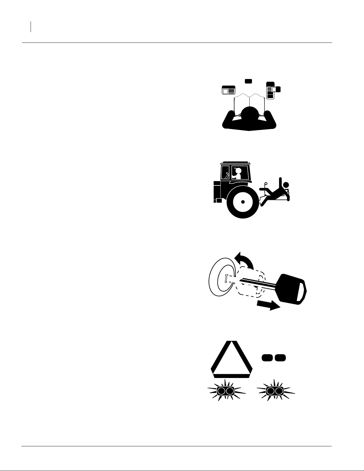
Keep Riders Off Machinery
Riders obstruct operator’s view. Riders could be
struck by foreign objects or thrown from machine.
▲ Never allow children to operate equipment.
Decals,” page 6.
▲ Keep all bystanders away from machine dur-
ing operation.
Shutdown and Storage
▲ Lower seeder and plow, put tractor in park,
turn off engine, and remove key.
▲ Detach and store seeder and plow in an area
where children do not play.
Use Safety Lights and Devices
Slow-moving tractors and implements can create
a hazard when driven on public roads. They are
difficult to see, especially at night.
▲ Use flashing warning lights and turn signals
whenever driving on public roads. Use lights
and devices provided with implement.
OFF
117-055M
3/20/06
Page 5

Transport Machinery Safely
▲ Comply with state and local laws.
▲ Maximum transport speed for implement is 20
mph. Do not exceed 20 mph. Never travel at a
speed that does not allow adequate control of
steering and stopping. Some rough terrains
require a slower speed.
▲ Check that your tractor has enough ballast to
handle the weight of implement. Refer to your
tractor operator’s manual for ballast requirements.
▲ Keep clear of overhead power lines and other
obstructions when transporting. Refer to transport dimensions under “Specifications and
Capacities,” page 22.
Important Safety Information
3
Avoid High Pressure Fluids
▲ Escaping fluid under pressure can penetrate
the skin, causing serious injury.
▲ Avoid the hazard by relieving pressure before
disconnecting hydraulic lines.
▲ Use a piece of paper or cardboard, NOT
BODY PARTS, to check for suspected leaks.
▲ Wear protective gloves and safety glasses or
goggles when working with hydraulic systems.
▲ If an accident occurs, see a doctor immedi-
ately. Any fluid injected into the skin must be
surgically removed within a few hours or gangrene may result.
3/20/06
117-055M
Page 6

LS10 and LS12
4
Practice Safe Maintenance
▲ Understand procedure before doing work. Use
proper tools and equipment. Refer to this manual for additional information.
▲ Work in a clean, dry area.
▲ Lower seeder and plow, put tractor in park,
turn off engine, and remove key before performing maintenance.
▲ Make sure all moving parts have stopped and
all system pressure is relieved.
▲ Allow seeder parts to cool completely.
▲ Do not grease or oil seeder while it is in opera-
tion.
▲ Inspect all parts. Make sure parts are in good
condition and installed properly.
▲ Remove buildup of grease, oil or debris.
▲ Remove all tools and unused parts from
seeder before operation.
OFF
Prepare for Emergencies
▲ Be prepared if a fire starts.
▲ Keep a first aid kit and fire extinguisher handy.
▲ Keep emergency numbers for doctor, ambu-
lance, hospital and fire department near
phone.
911
117-055M
3/20/06
Page 7
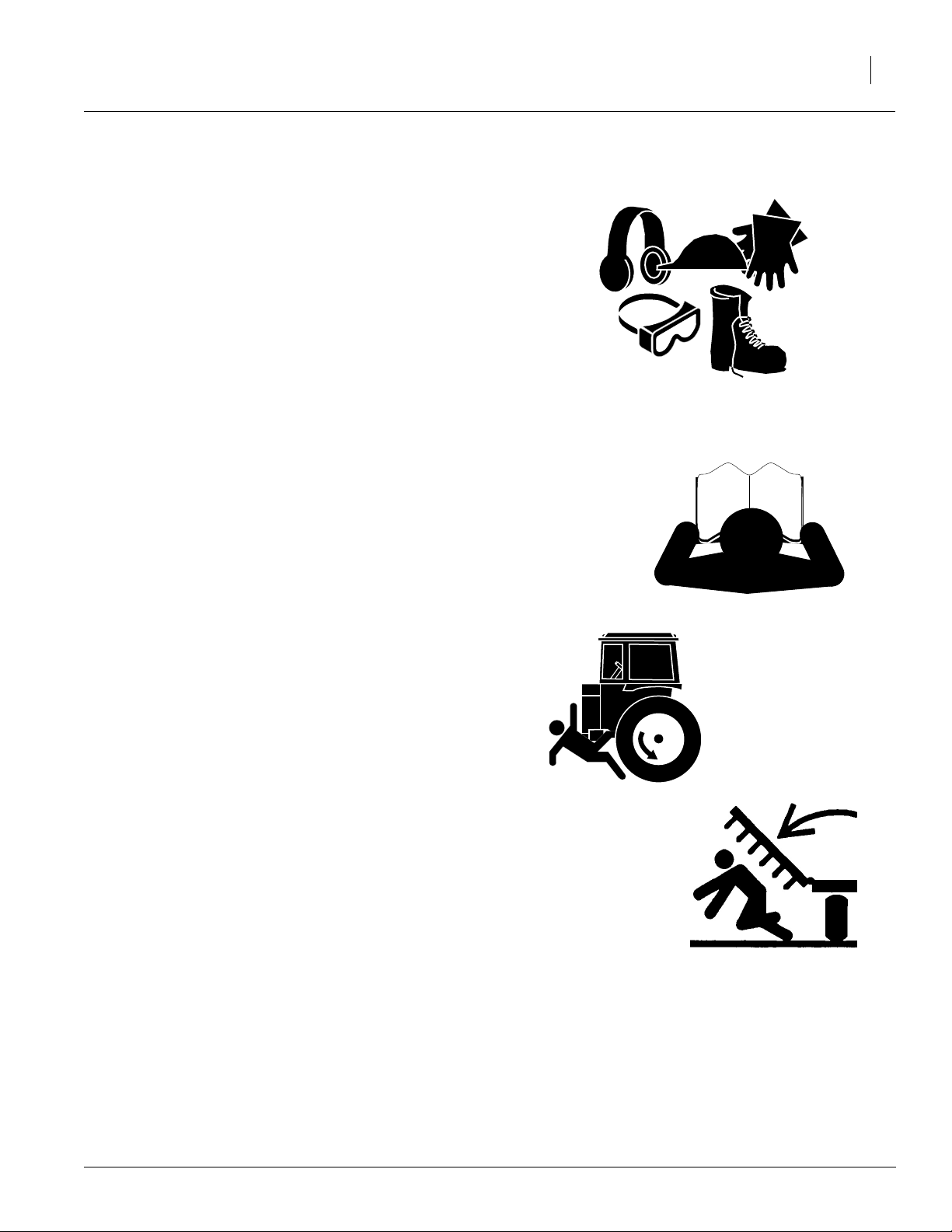
Wear Protective Clothing
▲ Wear protective clothing and equipment.
▲ Wear clothing and equipment appropriate for
the job. Avoid loose-fitting clothing.
▲ Because prolonged exposure to loud noise
can cause hearing impairment or hearing loss,
wear suitable hearing protection such as earmuffs or earplugs.
▲ Because operating equipment safely requires
your full attention, avoid wearing radio headphones while operating seeder.
Safety at All Times
Read thoroughly and understand instructions in
this manual before operating seeder. Read all instructions noted on the safety decals.
Important Safety Information
5
▲ Be familiar with all seeder functions.
▲ Operate seeder from the tractor driver’s seat
only.
▲ Do not leave seeder unattended with tractor
engine running.
▲ Do not dismount a moving tractor. Dismount-
ing a moving tractor could cause serious injury
or death.
▲ Do not stand between the tractor and seeder
during hitching.
▲ Keep hands, feet and clothing away from
power-driven parts. Keep away from moving
drive chain.
▲ Wear snug-fitting clothing to avoid entangle-
ment with moving parts.
▲ Watch out for wires, trees and other obstacles
when raising seeder.
▲ Make sure all bystanders are clear of working
area before operating seeder.
▲ Watch your step when walking on seeder lad-
der and walkboard. Falling from seeder could
cause severe injury or death.
3/20/06
117-055M
Page 8
LS10 and LS12
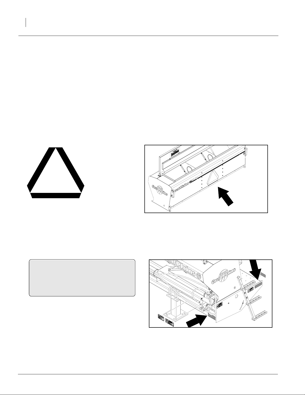
6
Safety Decals
Your seeder comes equipped with all safety decals in place. They were designed to help you
operate your implement safely.
▲ Read and follow decal directions.
▲ Keep all safety decals clean and legible.
▲ Replace all damaged or missing decals. Order
new decals from your Great Plains dealer.
Refer to this section for proper decal placement.
▲ When ordering new parts or components, also
request corresponding safety decals.
▲ To install new decals:
1. Clean area on which decal is to be
placed.
2. Peel backing from decal. Press firmly on
surface, being careful not to cause air
bubbles under decal.
818-003C
Slow Moving Vehicle
838-265C
Amber Reflectors
Reflectors on both left and right sides of seeder;
four reflectors total
18175
18174
117-055M
3/20/06
Page 9
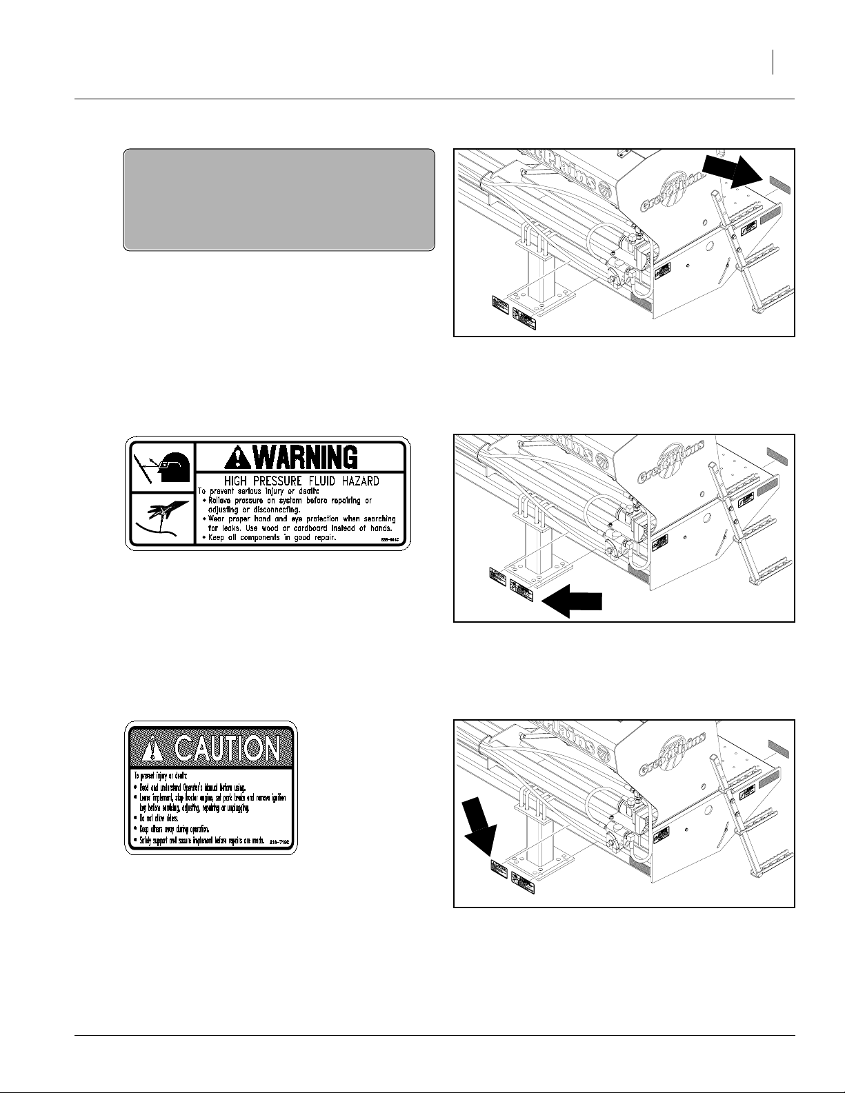
838-266C
Red Reflectors
Reflector at both ends of drill; two reflectors total
Important Safety Information
7
18174
838-094C
High Pressure
818-719C
General Instructions
18174
18174
3/20/06
117-055M
Page 10

LS10 and LS12
8
838-102C
Falling Hazard
Both ends of drill; two decals total
18174
818-860C
Moving Chain Hazard
18174
117-055M
3/20/06
Page 11

Introduction
Great Plains welcomes you to its growing family of
new product owners. This implement has been
designed with care and built by skilled workers using quality materials. Proper setup, maintenance
and safe operating practices will help you get
years of satisfactory use from the machine.
Description of Unit
The LS10 and LS12 are mounted seeding implements designed to seed small grains on newly
constructed levees. The seeder is designed to be
mounted on a levee plow. A variable-rate hydraulic motor drives seeding. Seeding rates are
adjusted by varying the speed of the hydraulic
motor and tractor speed.
Introduction
9
Intended Usage
Use this seeder in conjunction with a levee plow,
tandem disk, offset disk or one-way plow to seed
small grains or forages in a wide variety of
applications.
Models Covered
LS10 and LS12
Using This Manual
This manual will familiarize you with safety, assembly, operation, adjustments, troubleshooting
and maintenance. Read this manual and follow
the recommendations to help ensure safe and efficient operation.
The information in this manual is current at printing. Some parts may change to assure top
performance.
Definitions
Right-hand and left-hand as used in this manual
are determined by facing the direction the machine will travel while in use unless otherwise
stated.
3/20/06
117-055M
Page 12

LS10 and LS12
10
IMPORTANT: A crucial point of information related to the preceding topic. For safe and correct operation, read and follow the directions
provided before continuing.
NOTE: Useful information related to the preceding topic.
Owner Assistance
If you need customer service or repair parts, contact a Great Plains dealer. They have trained
personnel, repair parts and equipment specially
designed for Great Plains products.
Your machine’s parts were specially designedand
should only be replaced with Great Plains parts.
Always use the serial and model number when ordering parts from your Great Plains dealer. The
serial-number plate is shown in Figure 1.
Record your seeder model and serial number here
for quick reference:
Model Number: __________________________
Serial Number: ___________________________
Your Great Plains dealer wants you to be satisfied
with your new machine. If you do not understand
any part of this manual or are not satisfied with the
service received, please take the following
actions.
1. Discuss the matter with your dealership service manager. Make sure they are aware of
any problems so they can assist you.
2. If you are still unsatisfied, seek out the owner
or general manager of the dealership.
3. For further assistance write to:
Product Support
Great Plains Mfg. Inc., Service Department
PO Box 5060
Salina, KS 67402-5060
Figure 1
Serial Number Plate
17995
117-055M
3/20/06
Page 13

Preparation and Setup
This section will help you prepare your tractor and
seeder for use. Before field operation, you must
assemble the seeder onto a tillage implement and
hookup the hydraulic hoses.
Prestart Checklist
1. Read and understand “Important Safety Information,” beginning on page 1.
2. Check that all working parts are moving freely, bolts are tight, and cotter pins are spread.
3. Check that all safety decals and reflectors are
correctly located and legible. Replace decals
if damaged. See “Safety Decals,” page 6.
Preparation and Setup
11
Tools Required
• Forklift or hoist
• General hand tools
• 3/4-inch bolts and nuts
Mount Seeder on Plow
!
DANGER
Crushing hazard. You will be severely injured or killed
if the seeder falls on you. Secure seeder to lifting
equipment so seeder cannot fall. Do not walk or place
any body part under the seeder as the seeder is being
lifted.
!
WARNING
Obey all safety instructions from lifting equipment
manufacturer. Be sure lifting equipment has enough
capacity to lift seeder.
1. Secure seeder to forklift or hoist. Lift seeder
over plow.
3/20/06
2. Refer to Figure 2. Position using flat bars (A)
under plow frame and use 3/4-inch bolts to
clamp seeder to plow frame.
17993
Figure 2
Clamp Seeder to Plow
117-055M
Page 14

LS10 and LS12
12
3. Refer to Figure 3. Remove ladders from side
of seeder and rebolt ladders to seeder
through top set of holes in ladder.
Hydraulic Hose Hookup
18351
Figure 3
Reposition Ladder for Field Position
!
WARNING
Escaping fluid under pressure can have sufficient pressure to penetrate the skin. Check all hydraulic lines
and fittings before applying pressure. Fluid escaping
from a very small hole can be almost invisible. Use paper or cardboard, not body parts, and wear heavy
gloves to check for suspected leaks. If injured, seek
medical assistance from a doctor that is familiar with
this type of injury. Foreign fluids in the tissue must be
surgically removed within a few hours or gangrene
will result.
When hooking hydraulic hoses to tractor hook
hose coming from flow-control valve on seeder to
the pressurized side of the remote circuit. Hook
return line to sump. See Figure 4.
Check that seed-cup shaft on seeder is rotating in
the correct direction. When standing on the lefthand side of seeder, the shaft should rotate counterclockwise. If necessary, switch hoses at
outlets.
For future reference, refer to plastic hose holder to
distinguish hoses. See Figure 5.
17992
Figure 4
Hydraulic Hookup
NOTE: For tractors with open center hydraulic
systems, refer to your tractor manufacturer’s
recommendation before hooking up the hydraulics on this unit.
117-055M
17641
Figure 5
Hydraulic Hose Label
3/20/06
Page 15

Operating Instructions
This section covers general operating procedures. Experience, machine familiarity and the
following information will lead to efficient operation and good working habits. Always operate
farm machinery with safety in mind.
Prestart Checklist
!
WARNING
Escaping fluid under pressure can have sufficient pressure to penetrate the skin. Check all hydraulic lines
and fittings before applying pressure. Fluid escaping
from a very small hole can be almost invisible. Use paper or cardboard, not body parts, and wear heavy
gloves to check for suspected leaks. If injured, seek
medical assistance from a doctor that is familiar with
this type of injury. Foreign fluids in the tissue must be
surgically removed within a few hours or gangrene
will result.
Operating Instructions
13
1. Read “Important Safety Information,” page 1,
carefully.
2. Check all bolts, pins and fasteners. Torque as
specified on “Torque Values Chart,” page 23.
3. Lubricate as recommended areas listed under “Lubrication,” page 20.
4. Check seeder for worn or damaged parts. Repair or replace parts before going to the field.
5. Check hydraulic hoses and fittings for leaks.
Repair or replace before going to the field.
6. Check that seed cups and drive are working
properly and free from foreign material.
!
DANGER
Watch your step when walking on seeder ladder and
walkboard. Falling from seeder could cause severe injury or death.
3/20/06
117-055M
Page 16

LS10 and LS12
14
Field Operation
!
WARNING
Always park implement with plow wings swept back
and rear parking stand in the parking position for
maximum stability.
1. Mount seeder on levee plow or other compatible tillage implement. Position using flat bars
(A) under plow frame and use 3/4-inch bolts
to clamp seeder to plow frame. See Figure 6.
2. Hook hydraulic hoses to tractor outlets. See
Figure 7.
3. Fill seeder box with clean seed.
4. Set and calibrate seeding rate as explained
under “Seeding Rate Adjustment,” page 16.
5. Adjust seed-distribution door to the desired
position. Refer to “Distribution Panels,” page
17.
6. Check that seed-cup-doorhandles areset the
same across the drill. Refer to “Seed Cup
Doors,” page 16.
7. Pull forward, lower implement, engage hydraulic drive and begin seeding.
17993
Figure 6
Clamp Seeder to Plow
Transporting
!
WARNING
Transporting implement at high speeds or with a tractor without enough ballast could lead to loss of vehicle
control. Loss of vehicle control could lead to serious
road accidents, injury and death. Do not exceed 20
mph. Check that your tractor has enoughballast. Refer
to tractor operator’s manual for ballast requirements.
Before transporting seeder, follow and check
these items:
Unload seeder box. The seeder can be transported with a full box of grain, but the added
weight will increase stopping distance and decrease maneuverability. Unload seeder box
before transporting if at all possible.
Road rules. Comply with all federal, state and local laws when traveling on public roads.
Clearance. Remember that the seeder is wider
than the tractor. Allow for safe clearance.
17992
Figure 7
Hydraulic Hookup
117-055M
3/20/06
Page 17

Parking
!
WARNING
Always park implement with plow wings swept back
and rear parking stand in the parking position for
maximum stability.
For information on long-term storage, refer to
“Storage,” page 21.
1. Park implement on a level, solid surface.
2. Lower implement to the ground.
3. Shut off tractor.
4. Unplug hydraulic hoses from tractor outlets.
Position hoses on seeder frame so hose ends
are off the ground.
Operating Instructions
15
5. Place rear parking stand in position shown in
Figure 8.
6. Unhitch levee plow from tractor.
18350
Figure 8
Rear Parking Stand
3/20/06
117-055M
Page 18

LS10 and LS12
16
Seeding Rate Adjustment
To calibrate the seeding rate, the seeder and plow
must be hooked to the tractor that will be used in
the field andthe hydraulic drive must be hooked to
the tractor remotes.
1. Find desired seeding rate and ground speed
Adjustments
IMPORTANT: Calibrate the seeding rate with a
full box of seed.
on seeding rate chart, page 17. Determine
how many shaft rpms are needed for your
seeding rate and ground speed.
2. With tractor parked and idling in neutral, ad-
just tractor throttle up to field rpm.
3. Engage hydraulic drive. Count the number of
seed-cup-shaft revolutions per minute by using a tachometer.
4. Stop hydraulic drive. If shaft is turning too
slowly or quickly, loosen black knob and adjust flow control on hydraulic drive. See Figure
9. Move lever down to increase rpms. Move
lever up to reduce rpms.
5. When satisfied with flow-control setting, lock
black knob.
Seed Cup Doors
For rice and other small grains, move seed-cupdoor handles to the highest position. For larger
seeds, lower handles to the second or third position to reduce seed cracking. For seed-cup clean
out, move handles to the fourth, wide-open position. Make sure all handles are in the same
position before seeding.
18164
Figure 9
Flow Control Dial
117-055M
16491
Figure 10
Seed-Cup-Door Handle
3/20/06
Page 19

Seeding Rate Chart
Adjustments
17
Ground
Long Grain
Rice
Lamont Variety
47 lbs/bu
Short Grain
Rice
43 lbs/bu
Speed,
MPH Pounds per Acre
1 145 291 436 582 727 872 1018 1163 1309 1454
2 73 145 218 291 364 436 509 582 654 727
3 48 97 145 194 242 291 339 388 436 485
4 36 73 109 145 182 218 254 291 327 364
5 29 58 87 116 145 174 204 233 262 291
6 24 48 73 97 121 145 170 194 218 242
7 21 42 62 83 104 125 145 166 187 208
8 18 36 55 73 91 109 127 145 164 182
9 16 32 48 65 81 97 113 129 145 162
10 15 29 44 58 73 87 102 116 131 145
1 153 305 458 611 764 916 1069 1222 1374 1527
2 76 153 229 305 382 458 534 611 687 764
3 51 102 153 204 255 305 356 407 458 509
4 38 76 115 153 191 229 267 305 344 382
5 31 61 92 122 153 183 214 244 275 305
6 25 51 76 102 127 153 178 204 229 255
7 22 44 65 87 109 131 153 175 196 218
8 19 38 57 76 95 115 134 153 172 191
9 17 34 51 68 85 102 119 136 153 170
10 15 31 46 61 76 92 107 122 137 153
5 10 15 20 25 30 35 40 45 50
Distribution Panels
Seed is metered onto one of three distribution panels. The panels distribute seed behind the levee
plow. You can adjust the angle of these panels.
Seed-Cup Shaft, RPM
3/20/06
To adjust distribution panels, see Figure 11. Loosen bolts in rear panel slots. Adjust panel to desired
position and tighten bolts.
18165
Figure 11
Distribution Panels
117-055M
Page 20

LS10 and LS12
18
Troubleshooting
Problem Solution
Actual metering rate is different than
desired
Excessive seed cracking
Drill box not emptying evenly
Check seed-rate chart for proper seed-cup-shaft rpms for your seeding
rate. Refer to “Seeding Rate Chart,” page 17.
Adjust flow control on hydraulic drive. Refer to “Seeding Rate Adjustment,” page 16.
Calibrate flow to hydraulic drive when drill box is full of seed.
Refer to “Seeding Rate Adjustment,” page 16.
Check that seed-cup shaft is rotating is in the correct direction. If not,
reverse direction of flow to hydraulic drive by switching hoses at tractor outlets. Refer to “Hydraulic Hookup,” page 12.
Position seed-cup handles to a lower notch. Refer to “Seed Cup
Doors,” page 16.
Check that seed-cup shaft is rotating is in the correct direction. If not,
reverse direction of flow to hydraulic drive by switching hoses at tractor outlets. Refer to “Hydraulic Hookup,” page 12.
Certain models do not have the same number of cups between each
divider of bulkhead. The section with more cups will empty sooner.
117-055M
3/20/06
Page 21

Maintenance and Lubrication
Maintenance
Proper servicing and maintenance is the key to
long implement life. With careful and systematic
inspection, you can avoid costly maintenance,
downtime and repair.
Always turn off and remove tractor key before
making any adjustments or performing any
maintenance.
!
WARNING
You may be severely injured or killed by being crushed
under the falling implement. Always lower plow to the
ground before servicing the implement.
OFF
Maintenance and Lubrication
19
!
WARNING
Escaping fluid under pressure can have sufficient pressure to penetrate the skin. Check all hydraulic lines
and fittings before applying pressure. Fluid escaping
from a very small hole can be almost invisible. Use paper or cardboard, not body parts, and wear heavy
gloves to check for suspected leaks. If injured, seek
medical assistance from a doctor that is familiar with
this type of injury. Foreign fluids in the tissue must be
surgically removed within a few hours or gangrene
will result.
1. After using seeder for several hours, check all
bolts to be sure they are tight. Adjust idlers to
remove excess slack from drive chain.
2. Lubricate areas listed under “Lubrication,”
page 20.
3. Replace any worn, damaged or illegible safety decals. Order new decals from your Great
Plains dealer. Refer to “Safety Decals,” page
6.
3/20/06
117-055M
Page 22

LS10 and LS12
20
Lubrication
Multipurpose
spray lube
Drive Chain
Type of Lubrication: Chain lube
Quantity = Coat thoroughly
As
Required
Multipurpose
grease lube
17991
Multipurpose
oil lube
50
Intervals at which
lubrication is required
117-055M
3/20/06
Page 23

Storage
!
WARNING
Always park implement with plow wings swept back
and rear parking stand in the parking position for
maximum stability.
!
WARNING
Do not use ladder or walkboard when unit is not
hooked to tractor.
Store seeder where children do not play. If possible, store implement inside for longer life.
1. Clean seeder as necessary. Be sure the seed
box is cleaned completely before storing.
2. Lubricate as indicated under “Lubrication,”
page 20.
Removing Seeder from Plow
Maintenance and Lubrication
21
!
DANGER
Crushing hazard. You will be severely injured or killed
if the seeder falls on you. Secure seeder to lifting
equipment so seeder cannot fall. Do not walk or place
any body part under the seeder as the seeder is being
lifted.
!
WARNING
Obey all safety instructions from lifting equipment
manufacturer. Be sure lifting equipment has enough
capacity to lift seeder.
1. Reposition ladders for use as stands. Refer to
Figure 12. Remove ladders from side of seeder and rebolt ladders to seeder through lower
set of holes in ladder.
2. Secure seeder to forklift or hoist.
3. Refer to Figure 13. Disassemble flat bars (A)
that secure seeder to plow frame.
4. Lift seeder off plow.
Figure 12
Reposition Ladder
17994
3/20/06
17993
Figure 13
Disassemble Flat Bars
117-055M
Page 24

LS10 and LS12
22
Specifications and Capacities
LS10 LS12
Seed Cups per Seeder
Weight, Levee Seeder Alone
Working Width
Transport Width
Height, Levee Seeder Alone
Box Capacity
Tractor Requirements
One hydraulic remote One hydraulic remote
10 12
1,163 pounds 1,395 pounds
10 feet 12 feet
10 feet 4 inches 12 feet 6 inches
7 feet 2 inches 7 feet 2 inches
24 bushels 29 bushels
117-055M
3/20/06
Page 25

Appendix
Torque Values Chart
Bolt Head Identification
Appendix
Bolt Head Identification
23
Bolt Size
(Inches)
1
in-tpi
1/4" - 20 7.4 5.6 11 8 16 12 M 5 X 0.8 436597
1/4" - 28 8.5 6 13 10 18 14 M 6 X 1 7 5 11 8 15 11
5/16 - 18 15 11 24 17 33 25 M 8 X 1.25 17 12 26 19 36 27
5/16" - 24 17 13 26 19 37 27 M 8 X 1 18 13 28 21 39 29
3/8" - 16 27 20 42 31 59 44 M10 X 1.5 33 24 52 39 72 53
3/8" - 24 31 22 47 35 67 49 M10 X 0.75 39 29 61 45 85 62
7/16" - 14 43 32 67 49 95 70 M12 X 1.75 58 42 91 67 125 93
7/16" - 20 49 36 75 55 105 78 M12 X 1.5 60 44 95 70 130 97
1/2" - 13 66 49 105 76 145 105 M12 X 1 90 66 105 77 145 105
1/2" - 20 75 55 115 85 165 120 M14 X 2 92 68 145 105 200 150
9/16" - 12 95 70 150 110 210 155 M14 X 1.5 99 73 155 115 215 160
9/16" - 18 105 79 165 120 235 170 M16 X 2 145 105 225 165 315 230
5/8" - 11 130 97 205 150 285 210 M16 X 1.5 155 115 240 180 335 245
5/8" - 18 150 110 230 170 325 240 M18 X 2.5 195 145 310 230 405 300
3/4" - 10 235 170 360 265 510 375 M18 X 1.5 220 165 350 260 485 355
3/4" - 16 260 190 405 295 570 420 M20 X 2.5 280 205 440 325 610 450
7/8" - 9 225 165 585 430 820 605 M20 X 1.5 310 230 650 480 900 665
7/8" - 14 250 185 640 475 905 670 M24 X 3 480 355 760 560 1050 780
1" - 8 340 250 875 645 1230 910 M24 X 2 525 390 830 610 1150 845
1" - 12 370 275 955 705 1350 995 M30 X 3.5 960 705 1510 1120 2100 1550
1-1/8" - 7 480 355 1080 795 1750 1290 M30 X 2 1060 785 1680 1240 2320 1710
1 1/8" - 12 540 395 1210 890 1960 1440 M36 X 3.5 1730 1270 2650 1950 3660 2700
1 1/4" - 7 680 500 1520 1120 2460 1820 M36 X 2 1880 1380 2960 2190 4100 3220
1 1/4" - 12 750 555 1680 1240 2730 2010
1 3/8" - 6 890 655 1990 1470 3230 2380
1 3/8" - 12 1010 745 2270 1670 3680 2710
1 1/2" - 6 1180 870 2640 1950 4290 3160
1 1/2" - 12 1330 980 2970 2190 4820 3560
Grade 2 Grade 5
N · m2ft-lb3N · m ft-lb N · m ft-lb mm x pitch4N · m ft-lb N · m ft-lb N · m ft-lb
Torque tolerance + 0%, -15% of torquing values. Unless otherwise specified use torque values listed above.
Grade 8
Bolt Size
(Metric)
1
in-tpi = nominal thread diameter in inches-threads per inch
4
mm x pitch = nominal thread diameter in millimeters x thread pitch
5.8 8.8 10.9
Class 5.8 Class 8.8 Class 10.9
2
N· m = newton-meters
3
ft-lb= foot pounds
3/20/06
117-055M
Page 26

LS10 and LS12
24
Hydraulic Schematics
117-055M
17992
3/20/06
Page 27

Warranty
Great Plains Manufacturing, Incorporated warrants to the original purchaser that this seeding equipment will be free from defects in material
and workmanship for a period of one year from the date of original purchase when used as intended and under normal service and conditions
for personal use; 90 days for commercial or rental purposes. This Warranty is limited to the replacement of any defective part by Great Plains
Manufacturing, Incorporated and the installation by the dealer of any
such replacement part. Great Plains reserves the right to inspect any
equipment or part which are claimed to have been defective in material
or workmanship.
This Warranty does not apply to any part or product which in Great
Plains’ judgement shall have been misused or damaged by accident or
lack of normal maintenance or care, or which has been repaired or altered in a way which adversely affects its performance or reliability, or
which has been used for a purpose for which the product is not designed. This Warranty shall not apply if the product is towed at a speed
in excess of 20 miles per hour.
Claims under this Warranty must be made to the dealer which originally
sold the product and all warranty adjustments must by made through
such dealer. Great Plains reserves the right to make changes in materials or design of the product at any time without notice.
This Warranty shall not be interpreted to render Great Plains liable for
damages of any kind, direct, consequential, or contingent, to property.
Furthermore, Great Plains shall not be liable for damages resulting from
any cause beyond its reasonable control. This Warranty does not extend to loss of crops, losses caused by harvest delays or any expense
or loss for labor, supplies, rental machinery or for any other reason.
No other warranty of any kind whatsoever, express or implied, is
made with respect to this sale; and all implied warranties of merchantability and fitness for a particular purpose which exceed
the obligations set forth in this written warranty are hereby disclaimed and excluded from this sale.
This Warranty is not valid unless registered with Great Plains Manufacturing, Incorporated within 10 days from the date of original purchase.
Appendix
25
3/20/06
117-055M
Page 28

Index
C
Charts
seeding rate. . . . . . . . . . . . . . 17
torque values . . . . . . . . . . . . . 23
D
Distribution panels . . . . . . . . . . . . 17
F
Flow-control valve . . . . . . . . . . . . 12
H
Hydraulic drive
flow control . . . . . . . . . . . . . . 18
seeding rate adjustment . . . . 16
Hydraulic hoses
hookup. . . . . . . . . . . . . . . . . . 12
plastic hose holder. . . . . . . . . 12
Hydraulic pressure safety . . . . . . . 3
Hydraulic schematics . . . . . . . . . . 24
L
Ladder
positioning . . . . . . . . . . . . 12, 21
Lubrication . . . . . . . . . . . . . . . . . . 20
drive chain . . . . . . . . . . . . . . . 20
Seed calibration
See Seeding rate adjustment
Seed cracking . . . . . . . . . . . . . . . 18
Seed cup
clean out . . . . . . . . . . . . . . . . 16
door. . . . . . . . . . . . . . . . . . . . 16
handles . . . . . . . . . . . . . . . . . 16
shaft . . . . . . . . . . . . . . . . 12, 18
Seeding rate adjustment . . . . . . . 16
Storage . . . . . . . . . . . . . . . . . . 2, 21
T
Transport safety . . . . . . . . . . . . . . 3
Transporting . . . . . . . . . . . . . . . . 14
M
Maintenance . . . . . . . . . . . . . . . . 19
Maintenance safety . . . . . . . . . . . . 4
O
Operating instructions . . . . . . . . . 13
field operation . . . . . . . . . . . . 14
Operating safety. . . . . . . . . . . . . . . 5
P
Parking. . . . . . . . . . . . . . . . . . . . . 15
Plow
mounting . . . . . . . . . . . . . 11, 14
parking. . . . . . . . . . . . . . . . . . 15
removing . . . . . . . . . . . . . . . . 21
Preparation . . . . . . . . . . . . . . . . . 11
S
Safety decals . . . . . . . . . . . . . . . 2, 6
maintenance . . . . . . . . . . . . . 19
Safety lights . . . . . . . . . . . . . . . . . . 2
3/20/06
117-055M
Page 29

Great Plains Manufacturing, Inc.
Corporate Office: PO. Box 5060
Salina, Kansas 67402-5060 USA
 Loading...