

Page 1
Operator’s/Parts Manual
John Deere 30’ Dual 750
Flat Fold Marker
Planting Components
Read the operator’s manual entirely.Whenyouseethissymbol, the subsequent
instructions and warnings are serious - follow without exception. Your life and
!
the lives of others depend on it!
Cover illustration may show optional equipment not supplied with standard unit.
© Copyright 2002 Printed 3/20/2003
13747
205-052M
Page 2

Table of Contents
General Information . . . . . . . . . . . . . . . . . . . . . . . . .1
Introduction . . . . . . . . . . . . . . . . . . . . . . . . . . . . . . . .2
Using this Manual . . . . . . . . . . . . . . . . . . . . . . . . .2
Important Safety Information . . . . . . . . . . . . . . . . . .3
Owner’s Assistance . . . . . . . . . . . . . . . . . . . . . . . . .4
Operating and Assembly Instructions. . . . . . . . . . .5
General Operation & Repair . . . . . . . . . . . . . . . . .5
Transporting . . . . . . . . . . . . . . . . . . . . . . . . . . . . .5
Hydraulic System. . . . . . . . . . . . . . . . . . . . . . . . . . . .9
Adjusting the Hydraulics . . . . . . . . . . . . . . . . . . . .9
Maintenance & Lubrication . . . . . . . . . . . . . . . . . .10
Maintenance . . . . . . . . . . . . . . . . . . . . . . . . . . . .10
Breakaway Protection . . . . . . . . . . . . . . . . . . . . .10
Marker Transporting . . . . . . . . . . . . . . . . . . . . . .10
Lubrication . . . . . . . . . . . . . . . . . . . . . . . . . . . . .11
Troubleshooting. . . . . . . . . . . . . . . . . . . . . . . . . . . .13
Parts . . . . . . . . . . . . . . . . . . . . . . . . . . . . . . . . . . . . .14
Flat Fold Marker Assembly . . . . . . . . . . . . . . . . .14
Disk Assembly. . . . . . . . . . . . . . . . . . . . . . . . . . .16
Hydraulic Assembly. . . . . . . . . . . . . . . . . . . . . . .18
Hydraulic Cylinder. . . . . . . . . . . . . . . . . . . . . . . .20
Sequence Valve . . . . . . . . . . . . . . . . . . . . . . . . .22
Appendix . . . . . . . . . . . . . . . . . . . . . . . . . . . . . . . . .24
Warranty . . . . . . . . . . . . . . . . . . . . . . . . . . . . . . . . . .25
© Copyright 2002Allrights Reserved
Great Plains Manufacturing, Inc. provides this publication“as is” without warranty of any kind, either expressed or implied. While every precaution has been takenin the
preparationofthismanual,GreatPlainsMan uf acturing,Inc.assumesno responsibility for errorsoromissions.Neither is any liabilityassumedfordamages resulting from
theuseof the information contained herein. Great Plains Manufacturing,Inc. reservestheright to reviseandimproveits products as it sees fit. This publication describes
the state of this product at the time of its publication, and may not reflect the product in the future.
Great Plains Manufacturing, Incorporated Trademarks
The following are trademarks of Great Plains Mfg., Inc.: Application Systems, Ausherman, Land Pride, Great Plains
All other brands and product names are trademarks or registered trademarks of their respective holders.
Printed in the United States of America.
3/20/2003
205-052M
Page 3

General Inf ormation
Important Notice
Great Plains Manufacturing, Inc. provides this
publication “as is” without warranty of any kind,
either expressed or implied, while every
precaution has been taken in the preparation of
this manual, Great Plains Manufacturing, Inc.
assumesno responsibility forerrors or omissions.
Neither is any liability assumed for damages
resulting from the use of the information
contained herein. Great Plains Manufacturing,
Inc. reserves the right to revise and improve its
products as it sees fit. This publication describes
the state of this product at the time of its
publication, and may not reflect the product at all
times in the future.
Printed in the United States of America.
For your convenience, record your Model and the
Date Purchased on page 4. Have this information
beforeyouwhen callinga GreatPlains Authorized
Dealer.
General Information
1
This Operator’s Manual applies to the
Product Name listed below:
Flat Fold Marker
3/20/2003
205-052M
Page 4

John Deere 30’ Dual 750
2
Introduction
GreatPlains welcomesyouto itsgrowingfamilyof
new product owners. This Flat Fold Marker has
been designed with care and built by skilled
workers using quality materials. Proper setup,
maintenance and safe operating practices will
help you get years of satisfactory use from the
machine.
Description of Unit
The parts on your Flat Fold Marker have been
specially designed and should only be replaced
with genuine Great Plains parts. Therefore,
shouldyour Flat Fold Markerrequire replacement
parts go to your Great Plains Dealer.
Using This Manual
This manual will familiarize you with safety,
assembly, operation, adjustments and
maintenance. Read this manual and follow the
recommendations to help ensure safe and
efficient operation.
The information in this manual is current at
printing. Some parts may change to assure top
performance.
Definitions
The following terms are used throughout this
manual.
Right-hand and left-hand as used in this manual
are determined by facing the direction the
machine will travel while in use unless otherwise
stated.
IMPORTANT: A crucial point of information
related to the preceding topic. For safe and
correct operation, read and follow the
directions provided before continuing.
NOTE: Useful information related to the
preceding topic.
205-052M
3/20/2003
Page 5

Important Safety Information
Look for Safety Symbol
The SAFETY ALERT SYMBOL indicates there is
apotential hazard to personal safetyinvolvedand
extrasafety precaution must be taken. When you
see this symbol, be alert and carefully read the
message that follows it. In addition to design and
configuration of equipment, hazard control and
accident prevention are dependent upon the
awareness, concern, prudence and proper
training of personnel involved in the operation,
transport, maintenance and storage of
equipment.
Be Aware of Signal Words
Signal words designate a degree or level of
hazard seriousness.
Important Safety Information
!
3
DANGER indicates an imminently hazardous
situation which, if not avoided, will result in death
or serious injury. This signal word is limited to the
most extreme situations, typically for machine
components that, for functional purposes, cannot
be guarded.
WARNING indicates a potentially hazardous
situation which, if not avoided, could result in
death or serious injury, and includes hazards that
are exposed when guards are removed. It may
also be used to alert against unsafe practices.
CAUTION indicates a potentially hazardous
situationwhich, if not avoided,may result in minor
or moderate injury.It may also be used to alert
against unsafe practices.
DANGER
!
WARNING
!
CAUTION
!
3/20/2003
205-052M
Page 6

John Deere 30’ Dual 750
4
Owner Assistance
If you need customer service or repair parts,
contact a Great Plains dealer.They have trained
personnel, repair parts and equipment specially
designed for Great Plains products.
Yourmachine’sparts werespecially designedand
should only be replaced with Great Plains parts.
Always use the model number when ordering
parts from your Great Plains dealer.
Record your Model and Date Purchased here for
quick reference:
Model:________________________________
Date Purchased:_________________________
Your Great Plains dealer wants you to be
satisfied with your new machine. If you do not
understand any part of this manual or are not
satisfied with the service received, please take
the following actions.
1. Discuss the matter with your dealership
service manager.Makesure they are awareof
any problems so they can assist you.
2. If you are still unsatisfied, seek out the owner
or general manager of the dealership.
3. For further assistance write to:
Product Support
Great Plains Mfg. Inc., Service Department
PO Box 5060
Salina, KS 67402-5060
205-052M
3/20/2003
Page 7

Operating and Assembly Instructions
Operating and Assembly Instructions
5
Most accidents are the result of negligence and
carelessness, usually caused by failure of the
operator to follow simple but necessary safety
precautions.The followingsafety precautions are
suggested to help preventsuch accidents. The
safe operation of any machinery is a major
concern to consumers and manufacturers.Your
Flat Fold Marker has been designed with many
built-in safety features. However, no one should
operate this product before carefully reading this
Operators Manual.
General Operation & Repair
1. Never allow the Flat Fold Marker to be
operatedby anyonewho isunfamiliar withthe
operation of all functions of the unit. All
operators should read and thoroughly
understand the instructions given in this
manual prior to moving the unit.
2. Makesuresafetyrules areunderstoodbefore
operating machinery or tractor.
3. Never permit any persons other than the
operator to ride on the tractor.
4. Never permit any persons to stand near the
Flat Fold Marker while it is in operation.
5. Regulate your speed to the field conditions,
maintaining complete control at all times.
implements by using suitable supports and
block wheels.
13. If a hydraulic leak develops, correct it
immediately. Escaping hydraulic oil can have
extremely high pressure. A stream of high
pressure oil may easily penetrate the skin as
with modern needle-less vaccination
equipment - but with the exception that
hydraulicfluid maycause blood poisoning. It is
imperative that the connections are tight and
that all lines and pipes are in good condition. If
an injury is caused by the escaping hydraulic
fluid, see doctor at once!
14. Use a piece of cardboard or wood to detect
leaks of hydraulic oil under pressure.
15. Be sure to relieve all hydraulic pressure before
disconnecting any lines or pipes between the
implement and the tractor hydraulic system.
Keepall guards and shields in place.
Transporting
16. Use goodjudgementwhentransporting tractor
and implements on the highway. Always
maintain complete control of the machine.
17. Limit transport speed to 20 mph. Transport
only with a farm tractor of sufficient size and
horse power.
3/20/2003
6. After repairing or adjusting, make sure all
tools and parts are removed from the
implement before attempting to operate it.
7. Do not grease or oil machine while it is in
operation.
8. Loosefitting clothing should not be worn as it
may catch in moving parts.
9. Never dismount from a moving tractor.
10. Do not leavethe tractor or the implement
unattended with the engine running.
11. Do not stand between the tractor and the
implement during hitching.
12. Detach and store implements in an area
where children normally do not play. Stabilize
18. Always make sure flashing safety lights, “Slow
Moving Vehicle” emblem, and reflectors are in
place and visible prior to transporting the
machine on public roads.
19. Know your state and local laws concerning
highway safety and regulations. Comply with
these laws when transporting machinery.
20. Use warning flags or approved warning lights
at night and during other periods of poor
visibility. Do your best to prevent highway
accidents
205-052M
Page 8
John Deere 30’ Dual 750
6
John Deere Dual 750 Marker
See the "Parts Section" of this manual to identify
individual components not mentioned in these
installation instructions.
1. Placedrill in a loweredfieldposition. Fromeachend
of the drill box allow 16 ft. clearance for marker
assembly.
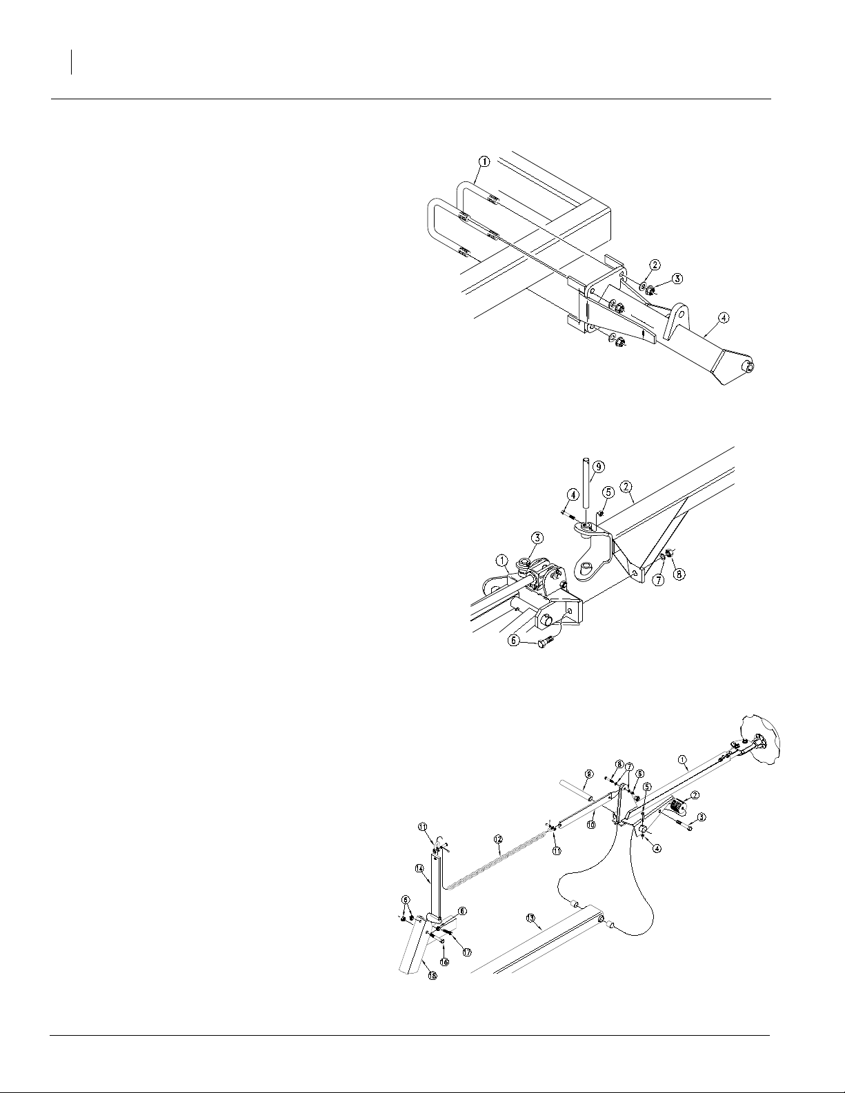
Refer to Figure 1
2. Attach the marker first section with mount (4) to the
drill frame as illustrated using the 3/4" x 6 1/32" Ubolts (1), 3/4" flat washer (2) and 3/4" locking flange
nut (3).
Refer to Figure 2
3. Assemble the marker in a horizontal position,
remove the port plugs in the hydraulic cylinder to
allow the fold cylinder to be extended. Then fold the
firstsection andthe liftlug channel(1) toahorizontal
position.
4. With the shear bar positioned towards the front (2),
align the holes of the second section with the holes
of the lift lug channel (1) and insert the hinge pin (9)
and bolt into place with 5/16" x 2" Gr 5 bolt (4) and
locknut (5). Also place the 7/16" x 2 1/4" Gr 5 shear
bolt (6) in position with lock washer (7) and nut (8).
Refer to Figure 3
5. Placethethird section(1) overtheend ofthesecond
section (13) and insert hinge pin (9) through the
secondandthirdsection pivot. Secure the hinge pin
(9) with 5/16" x 2" long bolt (5) and lock nut (4).
6. Bolt the chain bar weldment (14) to the first section
(18) with 3/8" x 3 1/4" long bolt (16) and lock nut (6).
The chain bar weldment (14) should pivot freely on
the 3/8" bolt (16). Bolt the chain bar (10) to the third
section(1) with the3/8" x 11/2" long bolt(8),washer
(7) and lock nut (6). The chain bar (10) should pivot
freely on the 3/8" bolt (8). Connect the marker chain
(2) between the chain bar (10) and chain bar
weldment (14) with 5/16" utility clevis (11). With the
marker disk adjusted for seeding width and disk
touching the ground, adjust chain length to remove
the slack. Adjustment should be made at the utility
clevis (11) nearest to the drill.
13696
Figure 1
Marker Mount Assembly
13697
Figure 2
Second Section Pivot Assembly
7. Thepurposeof the 3/8" x21/2" long stop bolt(17)is
tohold tension onthe marker chain(12) ONLY when
the marker is in folded position. Therefore; the 3/8"
stop bolt (17) and lock nuts (6) should be positioned
in the first section (18) so the head of the stop bolt
extends as little as possible. After marker is folded,
adjust stop bolt to tighten chain.
205-052M
13724
Figure 3
Third Section Pivot and Chain Assembly
3/20/2003
Page 9

Refer to Figure 4
8. When mounting the marker carrier arm (1), first
mount the transport mount arm (2) to the drill frame
using 1/2" x 4 1/32" x 7 1/4" long U-bolt (3), flat
washers (4), and flanged nuts (5). The transport
mount arm should be 50" - 60" awayfrom the box
end as shown. Next attach the marker carrier arm
(1) to the transport mounting arm (2) using the 1/2"
x 2" x 3" long U-bolts (6), flat washers (9) and
flanged nuts (7). The marker carrier arm should be
set at 31 3/8" - 31 7/8" above the drill frame as
shown.
9. Mount the support arm saddle (8) to the marker
carrier arm (1) with 1/2" x 2" x 3" long U-bolts (6),
and flanged nuts (7). The support saddle should be
centered under the marker chain and the square
tube of the second section, when folded to prevent
wear.The support arm should support the second
section parallel with the seed box lid. Adjustment
can be made by loosening the U -bolts that clamp
the marker carrier and slide marker carrier (1) up or
down to parallel the marker with the drill box lid.
Operating and Assembly Instructions
13699
Figure 4
Marker Support Assembly
7
Refer to Figure 5
10. Fold the marker to transport position. With the
marker chain (12) in the slot of the support arm
saddle, take up the slack in the marker chain by
threading
3/8"x2 1/2" long stop bolt (17) out against the chain
barweldment (14), lockthisstop bolt in position with
the two lock nuts (6).
11. The marker blade comes factory assembled. The
width of the mark that the blade makes can be
adjusted by changing the angle of the blade.This is
done by loosening the two 1/2" bolts in the blade
adjuster, pivoting the blade to the preferred angle
and tightening the bolts.
Refer to Figure 6
12. If desired, the angle ofthe bladecan bereversedby
turning the blade adjuster upside down and
reversingthe blade so the depth band is on the
inside.
11248
Figure 5
Blade Adjustment
3/20/2003
11757
Figure 6
Reversed Blade Adjustment
205-052M
Page 10
John Deere 30’ Dual 750
8
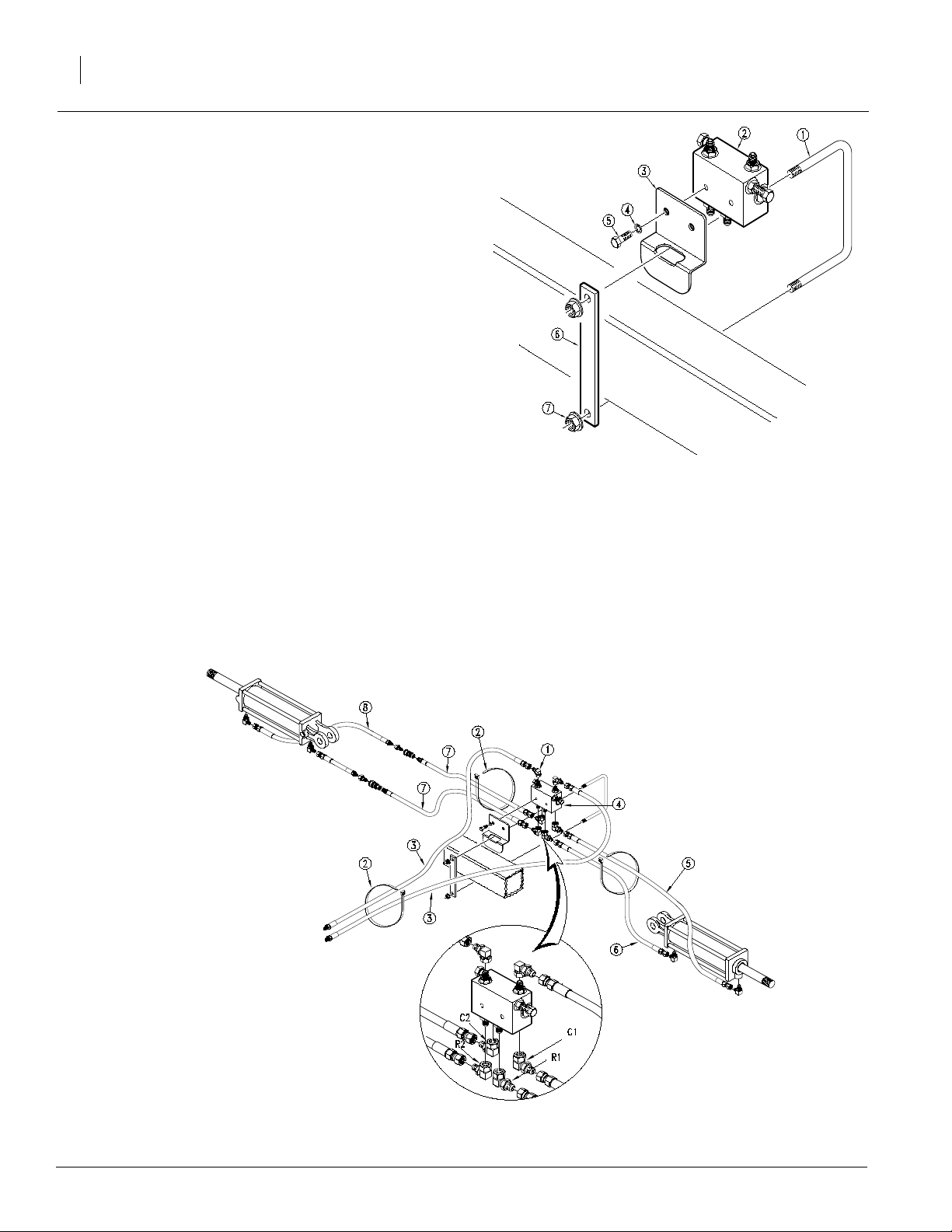
Refer to Figure 7
13. Install themarkervalvemount (3)close to thecenter
hitch on the tool bar frame of the front drill using the
U-bolt (1), bracket (6) and flange nut (7). Assemble
the valve (2) to the mount with the 4-port side
downward using two 3/8" x 3/4" long bolts (5) and
lock washers (4).
Refer to Figure 8
14. Route thehoses alongthe coulter frametube andtie
them to the tube with the releasable cable ties (2).
Connectthehosestothesequencevalve(4) withsix
JIC elbows (1). Note the port markings and refer to
Figure 8 for the proper connections.
15. Connect two252" long hoses(3)to the twotop ports
of the sequence valvewith two elbows (1) and route
them to the tongue and through the hose loop. Use
releasable cable ties sent with assembly to secure
hose to frame.
13700
Figure 7
Marker Valve
16. Use the 163" (5) and 136" (6) hose to connect the
marker on the front drill. Next, use the two 156" (7)
long hoses to go from the sequence valvealong the
dual hitch frame to the front of the second drill. The
remaining 252" hoses go to the marker on the
second drill. Quick connectors (purchased
separately)are used for easyremoval of the second
drill.
205-052M
13701
Figure 8
Marker Hydraulic Assembly
3/20/2003
Page 11

Hydraulic System
Adjusting The Hydraulics
1. Be sure tractor hydraulic reservoir is full.
2. With the markers in field position, crack the
hydraulics hose fittings located at the base end of
one of the cylinders. With the tractor at an idle
speed, activate the tractor hydraulics valve until
hydraulicoilseeps outaround thehose end.Tighten
the hose end fittings. Repeat this process for the
hose at the rod end of the cylinder.Crackthe fittings
on the back side of the sequence valve until
hydraulic oil seeps out. Tighten and repeat for the
opposite cylinder.
3. Cycle each cylinder 3 or 4 times slowly. Both arms
shouldmoveto the verticalpositionon thefirstmove
and then they should lower and raise alternately as
the hydraulic lever is operated.
4. Foldandunfoldthemarker(s) slowlyin order towork
all theairoutofyourmarker hydraulics.Use caution
when folding and unfolding the marker for the first
time, and check for pinching and kinking of hoses.
!
CAUTION
Never allow anyone near the drill when cycling the markers.
Hydraulic System
!
CAUTION
Excessive folding speeds can cause marker damage!
!
CAUTION
Escaping Fluid under pressure can have sufficient force to
penetrate the skin. Check all hydraulic lines and hoses before
applying pressure. Fluid escaping from a very small hole can
be almost invisible. Use paper or cardboard, not body parts,
to check for suspected leaks. If injured, seek medical
assistance from a doctor that is familiar with this type of
injury.Foreign fluids in the tissue must be surgicallyremoved
within a few hours or gangrene will result.
General Notes
The markers cycle in the following sequence
(1)Right Up, Left Up
(2)Right Down, Left Up
(3)Right Up, Left Up
(4)Right Up, Left Down
(5)Sequence Repeats
9
5. The marker hydraulic system is equipped with
needle valves to control how fast each marker
operates. The needle valves are built into the
sequencevalvebody.Therearetwo hexadjustment
heads, one for raising the markers, and one for
lowering the markers. These are stamped in the
valve body. To adjust the speed of each marker,
screwthe needle valveclockwise to adjust the raise
or lower marker speed to a low setting. Fold the
marker up and down a few times and recheck for
pinching and kinking of hoses. With the tractor
engine at an operating rpm, adjust the needle valve
to limit the marker to a safe operating speed.
Excessive folding speeds can cause marker
damage.
NOTE: JIC fittings do not require high torque. JIC and ORingfittings do not require sealant. Alwaysuse liquid pipe
sealant when adding or replacing pipe thread fittings. To
avoid possible danger of cracking hydraulic fittings from
over tightening,
DO NOT use plastic sealant tape.
3/20/2003
205-052M
Page 12

John Deere 30’ Dual 750
10
Maintenance and Lubrication
Maintenance
Proper servicing and adjustment is the key to the long
life of any farm implement. With careful and systematic
inspection, you can avoidcostly maintenance, time and
repair.
Breakaway Pr otection
The marker arm is attached to the marker body with a
7/16" breakaway bolt. If excessive force is put on the
markerduring operation,theboltwillbreak,allowingthe
marker arm to swing away rather than cause damage to
the marker.
NOTE: The breakaway bolt is a 7/16"-14 x 2 1/4"
long grade 5 (G.P. # 802-234C). It is identified as a
grade 5 by having three marks on the head. If it
breaks, it must be replaced by an equivalent grade
5 bolt to prevent marker damage.
Marker Transporting
Alwaystransport the marker with it folded in the flat fold
position.
205-052M
3/20/2003
Page 13

Lubrication Symbols
50
Maintenance and Lubrication
As
Required
11
Lubrication is required every 50 hours of operation.
10
Lubrication
13441
Use a multi-purpose spray lub. Use as required.
Do not over lubricate.
Seasonally
Lubrication is requiredLubrication is required every 10 hours of operation.
25
1st Hinge Zerk
Type of Lubrication: NLGI Grade 2 or 3 grease lubricant
3/20/2003
25
2nd Hinge Zerk
13723
Type of Lubrication: NLGI Grade 2 or 3 grease lubricant
205-052M
Page 14

John Deere 30’ Dual 750
12
Lubrication
25
3rd Hinge Zerk
13702
12436
Type of Lubrication: NLGI Grade 2 or 3 grease lubricant
Seasonally
Disk Bearings
Type of Lubrication: NLGI Grade 2 or 3 grease lubricant
205-052M
3/20/2003
Page 15

Troubleshooting
Problem Solution
Troubleshooting
13
Hydraulic marker functioning
improperly
Blade does not mark
Hydraulic marker functioning
improperly
Check all hose fittings and connections for air and oil leaks.
The chain on the folding marker should be slack when the marker is both fully extended
and fully raised.
Check tractor hydraulic oil level.
Check all bolts and fasteners.
If needle valve is plugged; open valve, cycle markers, and reset the needle valve.
Double selector valve positioned for fold cylinders. Shift valve to marker sequence posi-
tion.
The marker folding linkage and chain must have enough slack to allow the marker disk to
drop down into depression in the field. Maximum down float should be limited by the
slots at the rod end of the marker cylinder, and not by the chain. Read the adjustments
section of this manual when adding slack to chain.
The blade may be reversed to pull dirt in or throw dirt out depending on soil conditions.
An optional smooth blade is available through your Great Plains dealer. The notch blade
comes with your marker as standard equipment.
Check all hose fittings and connections for air and oil leaks.
The chain on the folding marker should be slack when the marker is both fully extended
and fully raised.
Check tractor hydraulic oil level.
Check all bolts and fasteners.
Blade does not mark
If needle valve is plugged; open valve, cycle markers, and reset the needle valve.
Double selector valve positioned for fold cylinders. Shift valve to marker sequence posi-
tion.
The marker folding linkage and chain must have enough slack to allow the marker disk to
drop down into depression in the field. Maximum down float should be limited by the
slots at the rod end of the marker cylinder, and not by the chain. Read the adjustments
section of this manual when adding slack to chain.
The blade may be reversed to pull dirt in or throw dirt out depending on soil conditions.
An optional smooth blade is available through your Great Plains dealer. The notch blade
comes with your marker as standard equipment.
3/20/2003
205-052M
Page 16
John Deere 30’ Dual 750
14
Parts
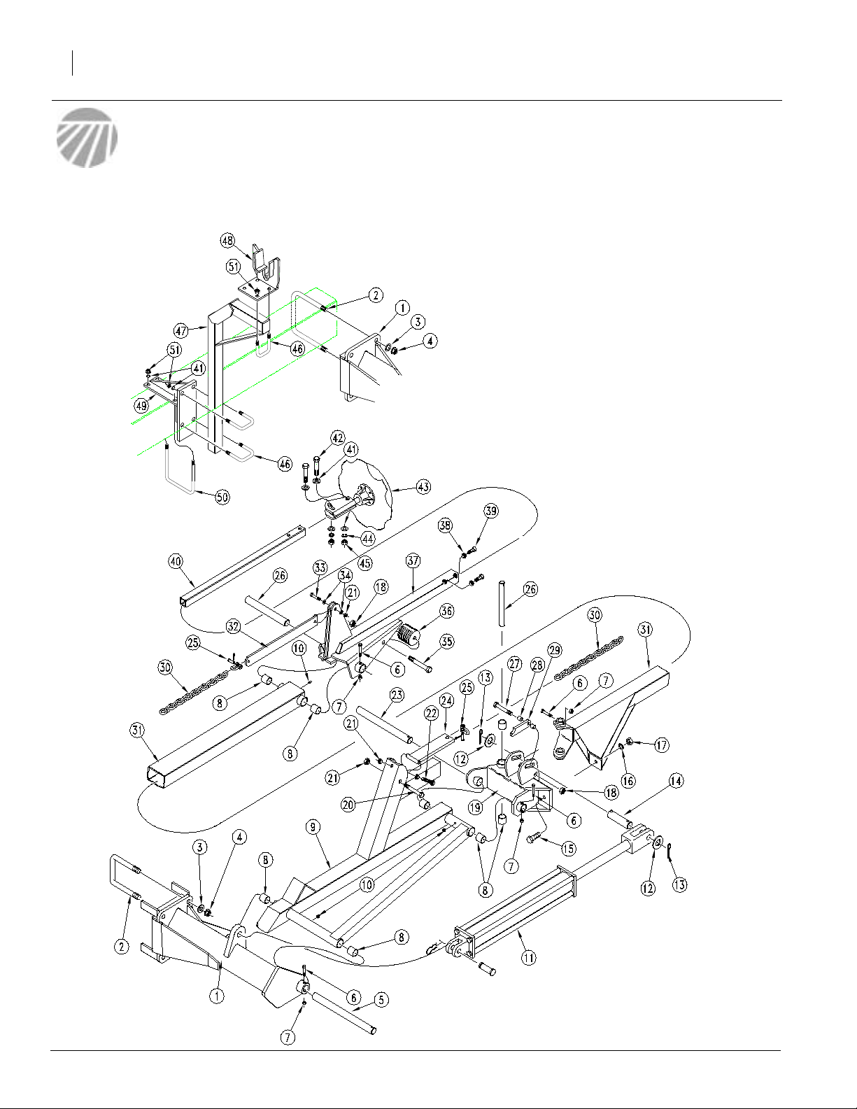
Flat Fold Marker Assembly
13703
205-052M
3/20/2003
Page 17

Ref. Part No. Description
1. 205-048H DUAL JD750 MARKER MOUNT LH Shown.
205-047H DUAL JD750 MARKER MOUNT RH
2. 806-123C U-BOLT 3/4-10 X 6 1/32 X 6 3/4
3. 804-024C WASHER FLAT 3/4 USS PLT
4. 803-181C NUT HEX FLANGE LOCK 3/4-10 PLT
5. 113-312D FIRST PIVOT SHAFT
6. 802-115C HHCS 5/16-18X2 GR5
7. 803-011C NUT LOCK 5/16-18 PLT
8. 890-005C BUSHING CYL 1 1/4 X 1 X 1
9. 113-180H LH FIRST SECTION Shown.
113-188H RH FIRST SECTION
10. 800-001C GREASE ZERK STRAIGHT 1/4-28
11. 810-118C CYL 2.5X20X1.12 ROD (TIE)1 PIN
12. 804-029C WASHER FLAT 1 SAE
13. 805-058C PIN COTTER 3/16 X 2
14. 113-248D PIN 1 OD X 4.34 USABLE
15. 802-234C HHCS 7/16-14X2 1/4 GR5
16. 804-014C WASHER LOCK 7/16 PLT
17. 803-015C NUT HEX 7/16-14 PLT
18. 803-019C NUT LOCK 1/2-13 PLT
19. 113-350H NO-TILL BREAKAWAY JOINT LH Shown.
113-351H NO-TILL BREAKAWAY JOINT RH
20. 802-168C HHCS 3/8-16X3 1/4 GR5
21. 803-013C NUT LOCK 3/8-16 PLT
22. 802-261C HHCS 3/8-16X2 1/2 GR5 FTHD
23. 113-313D SECOND PIVOT SHAFT
24. 113-200H CHAIN BAR WELDMENT
25. 890-018C 5/16 x 1 1/4 UTILITY CLEVIS
26. 113-311D HINGE PIN
27. 802-201C HHCS 1/2-13X4 3/4 GR5
28. 113-325D STOP BUSHING
29. 113-324D CYLINDER STOP
30. 113-328D 24’ MARKER CHAIN
113-319D MARKER CHAIN 30’
31. 113-342H NO-TILL MARKER 24’ 2ND SECTION
113-341H NO-TILL MARKER 30’ 2ND SECTION
32. 113-323D CHAIN BAR
33. 802-022C HHCS 3/8-16X1 1/2 GR5
34. 804-011C WASHER FLAT 3/8 USS PLT
35. 802-260C HHCS 1/2-13X7 GR5
36. 113-398D RUBBER TUBE RD 3 OD X 5 LONG
37. 113-344H NO-TILL MARKER 24’ 3RD SECTION
113-343H NO-TILL MARKER 30’ 3RD SECTION
38. 803-036C NUT HEX JAM 1/2-13 PLT
39. 801-013C SCREW SET SQ HD 1/2-13X1 1/2G5
40. 113-379D NO-TILL 24’ 4TH SECT TUBE
113-378D NO-TILL 30’ 4TH SECT TUBE
41. 804-017C WASHER FLAT 1/2 USS PLT
42. 802-041C HHCS 1/2-13X3 1/2 GR5
43. 113-360S NOTILL MRKR DSK & 4BLT HUB ASY Refer to page 16 for breakdown.
44. 804-015C WASHER LOCK SPRING 1/2 PLT
45. 803-020C NUT HEX 1/2-13 PLT
46. 806-005C U-BOLT 1/2-13 X 2 X 3 GR 5
47. 113-197H MARKER CARRIER
48. 113-365H NO-TILL SADDLE REST WELDMENT
49. 205-036H TRANSPORT ARM MOUNT WLDMNT
50. 806-069C U-BOLT 1/2-13 X 4 1/32 X 7 1/4
51. 803-169C NUT HEX FLG. LOCK 1/2-13 PLT.
Parts
15
3/20/2003
205-052M
Page 18

John Deere 30’ Dual 750
16
Disk Assembly
12426
205-052M
3/20/2003
Page 19

Ref. Part No. Description
1. 113-563S MARKER DISC & HUB ASSEMBLY
113-564S REP BY 113-563S
113-372S REP BY 113-564S
2. 113-562H 1 SPINDLE MARKER WELDMENT
3. 816-014C TINE GAUGE MARKER HUB SEAL
4. 822-030C BEARING CONE L44643
5. 822-080C BEARING CUP L44610
6. 890-614C GREASE CAP #1505
7. 815-001C TINE GW HUB
8. 804-025C WASHER FLAT 3/4 SAE PLT
9. 803-053C NUT HEX SLOTTED 3/4-16
10. 805-019C PIN COTTER 5/32 X 1 PLT
11. 820-094C 16 4-BOLT NOTCHED MARKER DISK
12. 133-369H DEPTH BAND 10 4-BOLT 4B.C.
13. BO-47 NEILSON STUD 1/2-20UNF X 1 13/16
14. 803-159C NUT LUG 1/2-20 X 60 DEG PLT
Parts
17
3/20/2003
205-052M
Page 20

John Deere 30’ Dual 750
18
Hydraulic Assembly
13725
205-052M
3/20/2003
Page 21

Ref. Part No. Description
1. 810-118C CYL 2.5X20X1.12 ROD (TIE)1 PIN
2. 811-065C EL 9/16MJIC 9/16MORB
3. 811-248C HH1/4R1 163 9/16FJIC
4. 811-130C HH1/4R1 252 1/2MNPT 9/16FJIC
5. 802-014C HHCS 3/8-16X3/4 GR5
6. 804-013C WASHER LOCK SPRING 3/8 PLT
7. 148-425D MARKER VALVE MOUNT
8. 811-169C EL 9/16MJIC 9/16FJIC
9. 800-035C CABLE TIE .31X28 8DIA 120LB
10. 811-167C HH1/4R1 136 9/16FJIC
11. 806-022C U-BOLT 3/8-16 X 6 1/32 X 5 PLT
12. 803-068C NUT HEX FLANGE 3/8-16 PLT
13. 205-029D U-BOLT BRACKET
14. 810-197C VALVE,SEQUENCE SHOEMAKER
15. 811-436C HH1/4R1 156 9/16FJIC 1/2MNPT
16. 817-348C PLASTIC HOSE LABEL
Parts
19
3/20/2003
205-052M
Page 22

John Deere 30’ Dual 750
20
Hydraulic Cylinder (810-118C)
10035
205-052M
3/20/2003
Page 23

Ref. Part No. Description
1. 1M6006 CLEVIS
2. 2M3326 ROD
3. 3R0310 MW HEAD
4. 4M3108 MW PISTON
5. 5M3128 TUBE
6. 6R0158 BASE MIDWAY
7. 7M3328 TIE ROD
8. 2A0208 CLEVIS PIN
9. * WIPER SEAL
10. * O-RING
11. * BACK UP (ROD)
12. * O-RING
13. * BACK UP (PISTON)
14. 2A0022 PISTON NUT
15. 2A0012 CLEVIS NUT
16. 2A0012 TIE ROD NUT
17. 802-023C HHCS 3/8-16X1 3/4 GR5
18. 2A0132 PIN CLIP
19. 810-210C SEAL KIT MW 2.5 CYL 3A3102
Parts
21
* AVAILABLE IN SEAL KIT.
3/20/2003
205-052M
Page 24

John Deere 30’ Dual 750
22
Sequence Valve
12024
205-052M
3/20/2003
Page 25

Ref. Part No. Description
1. 3089 BODY, SEQUENCE VALVE
2. 1088-908 O-RING
3. 1132-08 PLUG, HEX SOCKET
4. 1179 NEEDLE, FLOW CONTROL
5. 1217 PIN, .125" SPRING PIN
6. 1211 SPRING, COMPRESSION
7. * O-RING Seal kit only
8. * RING, TEFLON BACK-UP Seal kit only
9. 1180 SCREW, FLOW CONTROL ADJUSTMENT
10. 1218 HEX, JAM NUT ZINK PLATED
11. * SPRING, DETENT Seal kit only
12. * CHROMIUM STEEL BALLS Seal kit only
13. * CHROMIUM STEEL BALL Seal kit only
14. * SPRING Seal kit only
15. 1088-906 O-RING
16. 1182 FITTING, PORT ADAPTOR
17. 1132-05 HEX, SOCKET O-RING PLUG
18. 1088-905 O-RING
19. 1092-6-6 CONNECTOR, STRAIGHT
20. 2153 SPOOL, MARKER SEQUENCE .055" ORIFICE
810-456C SEAL KIT SHOEMAKER #1223 Not shown
Parts
23
3/20/2003
205-052M
Page 26

John Deere 30’ Dual 750
24
Appendix
Torque V alues Chart
Bolt Head Identification
Bolt Head Identification
Bolt Size
(Inches)
1
in-tpi
1/4" - 20 7.4 5.6 11 8 16 12 M 5 X 0.8 4 3 6 5 9 7
1/4" - 28 8.5 6 13 10 18 14 M 6 X 1 7 5 11 8 15 11
5/16 - 18 15 11 24 17 33 25 M 8 X 1.25 17 12 26 19 36 27
5/16" - 24 17 13 26 19 37 27 M 8 X 1 18 13 28 21 39 29
3/8" - 16 27 20 42 31 59 44 M10 X 1.5 33 24 52 39 72 53
3/8" - 24 31 22 47 35 67 49 M10 X 0.75 39 29 61 45 85 62
7/16" - 14 43 32 67 49 95 70 M12 X 1.75 58 42 91 67 125 93
7/16" - 20 49 36 75 55 105 78 M12 X 1.5 60 44 95 70 130 97
1/2" - 13 66 49 105 76 145 105 M12 X 1 90 66 105 77 145 105
1/2" - 20 75 55 115 85 165 120 M14 X 2 92 68 145 105 200 150
9/16" - 12 95 70 150 110 210 155 M14 X 1.5 99 73 155 115 215 160
9/16" - 18 105 79 165 120 235 170 M16 X 2 145 105 225 165 315 230
5/8" - 11 130 97 205 150 285 210 M16 X 1.5 155 115 240 180 335 245
5/8" - 18 150 110 230 170 325 240 M18 X 2.5 195 145 310 230 405 300
3/4" - 10 235 170 360 265 510 375 M18 X 1.5 220 165 350 260 485 355
3/4" - 16 260 190 405 295 570 420 M20 X 2.5 280 205 440 325 610 450
7/8" - 9 225 165 585 430 820 605 M20 X 1.5 310 230 650 480 900 665
7/8" - 14 250 185 640 475 905 670 M24 X 3 480 355 760 560 1050 780
1" - 8 340 250 875 645 1230 910 M24 X 2 525 390 830 610 1150 845
1" - 12 370 275 955 705 1350 995 M30 X 3.5 960 705 1510 1120 2100 1550
1-1/8" - 7 480 355 1080 795 1750 1290 M30 X 2 1060 785 1680 1240 2320 1710
1 1/8" - 12 540 395 1210 890 1960 1440 M36 X 3.5 1730 1270 2650 1950 3660 2700
1 1/4" - 7 680 500 1520 1120 2460 1820 M36 X 2 1880 1380 2960 2190 4100 3220
1 1/4" - 12 750 555 1680 1240 2730 2010
1 3/8" - 6 890 655 1990 1470 3230 2380
1 3/8" - 12 1010 745 2270 1670 3680 2710
1 1/2" - 6 1180 870 2640 1950 4290 3160
1 1/2" - 12 1330 980 2970 2190 4820 35604mm x pitch = nominal thread diameter in millimeters x thread pitch
Grade 2 Grade 5
N · m2ft-lb3N · m ft-lb N · m ft-lb mm x pitch4N · m ft-lb N · m ft-lb N · m ft-lb
Torque tolerance + 0%, -15% of torquing values. Unless otherwise specified use torque values listed above.
Grade 8
Bolt Size
(Metric)
1
in-tpi = nominal thread diameter in inches-threads per inch
5.8 8.8 10.9
Class 5.8 Class 8.8 Class 10.9
2
N· m = newton-meters
3
ft-lb= foot pounds
205-052M
3/20/2003
Page 27

Warranty
Great Plains Manufacturing, Incorporated warrants to the original purchaser that this seeding equipment will be free from defects in material
and workmanship for a period of one year from the date of original purchasewhenused as intended and under normal service and conditions
for personal use; 90 days for commercial or rental purposes. This Warranty is limited to the replacement of any defective part by Great Plains
Manufacturing, Incorporated and the installation by the dealer of any
such replacement part. Great Plains reserves the right to inspect any
equipment or part which are claimed to have been defective in material
or workmanship.
This Warranty does not apply to any part or product which in Great
Plains’ judgement shall have been misused or damaged by accident or
lack of normal maintenance or care, or which has been repaired or altered in a way which adversely affects its performance or reliability, or
which has been used for a purpose for which the product is not designed. This Warranty shall not apply if the product is towed at a speed
in excess of 20 miles per hour.
Claims under this Warranty must bemade tothe dealerwhichoriginally
sold the product and all warranty adjustments must by made through
such dealer. Great Plains reserves the right to make changes in materials or design of the product at any time without notice.
This Warranty shall not be interpreted to render Great Plains liable for
damages of any kind, direct, consequential, or contingent, to property.
Furthermore,Great Plains shallnotbe liable fordamagesresulting from
any cause beyond its reasonable control. This Warranty does not extend to loss of crops, losses caused by harvest delays or any expense
or loss for labor, supplies, rental machinery or for any other reason.
No other warranty of any kind whatsoever, express or implied, is
made with respect to this sale; and all implied warranties of merchantability and fitness for a particular purpose which exceed
the obligations set forth in this written warranty are hereby disclaimed and excluded from this sale.
This Warranty is not valid unless registered with Great Plains Manufacturing, Incorporated within 10 days from the date of original purchase.
Appendix
25
3/20/2003
205-052M
Page 28

Great Plains Manufacturing, Inc.
Corporate Office: P.O.Box 5060
Salina, Kansas 67402-5060 USA
 Loading...