

Page 1
Great Plains Mfg., Inc.
Installation Instructions
3-8 Shank Sub-Soiler Inline Ripper
Inline Ripper Gauge Wheel Jack Kit
Used with:
• 3-8 Shank Sub-Soiler Inline Ripper
General Information
When you see this symbol, the subsequent instructions and
warnings are serious - follow without exception. Your life and
!
!
the lives of others depend on it!
These instructions explain how to install the Inline Ripper Gauge Wheel Jack Kit. The Inline Ripper Gauge
Wheel Jack Kit allows for jacks to be added to the Inline Ripper Gauge Wheels to adjust the depth of the
ripper. These instructions apply to:
596-157A Inline Ripper Gauge Wheel Jack Kit
Manual Update
Refer to the 3-8 Shank Sub-Soiler Inline Ripper operator’s man ual for detailed information on safely
operating, adjusting, troubleshooting and maintaining
the Inline Ripper Gauge Wheel Jack. Ref er to the
parts manual for part identification.
596-086M Operator’s Man ual
596-086P Parts Manual
Assembly Instructions
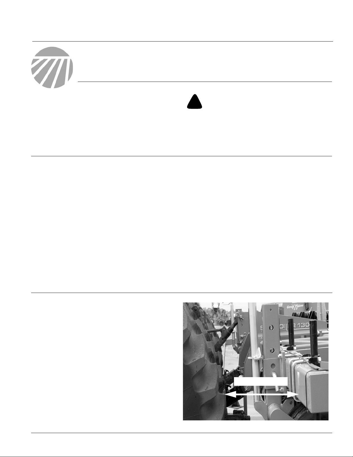
Refer to Figure 1
NOTE: Mounting the jack to the gauge wheel arm may
cause clearance problems with the Great Plains SubSoiler Hitch or with tractor tires if the ripper is 3-point
mounted. If gauge mounts line up with tires or
hitch, be sure there is at least 12" clearance between front of the frame tube and tires or hitch. If
the 12" clearance exists, the gauge wheels will mount
on the front side of the front frame tube. Please refer to
the following instructions on page 2. If there is not 12"
clearance, the gauge wheels will need moved out towards the end of the frame or need mounted on the
back side of the front frame tube. Please ref er to page
4 for these instructions.
Before You Start
Page 7 is a detailed listing of parts included in the
Inline Ripper Gauge Wheel Jack Kit. Use this list
to inventory parts received.
T ools Required
• Basic Hand Tools
• Welder
• DA Grinder
12" Clearance
© Copyright 2005 Printed
5/4/2005
Figure 1
23176
596-158M
Page 2
Inline Ripper Gauge Wheel Jack Kit
2
Mounting the Jack on Gauge Wheels with 12"
Clearance
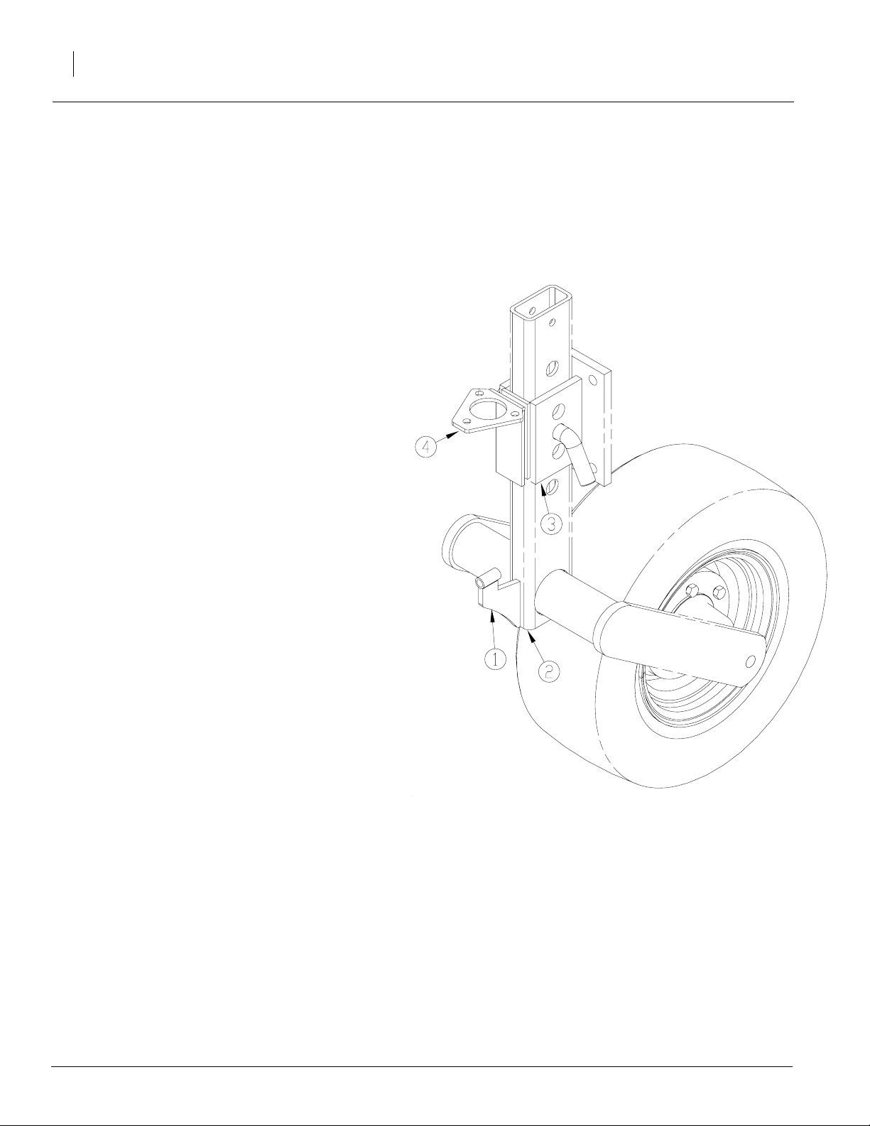
Refer to Figure 2
1. After determining 12" clearance between the front
of the frame tube to tires or hitch, grind paint on
bottom portion of front of the gauge wheel arm
(2).
2. Center and align gauge wheel jack lower mount
(1) flush with the bottom of the gauge wheel arm
(2). Weld mount (1) on arm (2).
3. Grind paint on the gauge wheel mount (3). Center
and align upper jack mount plate (4) flush with the
bottom of the gauge wheel mount (3). Weld plate
(4) to gauge wheel mount (3).
Great Plains Mfg., Inc.
4. Repeat steps 1-3 on opposite side of inline ripper
frame. Paint new parts with Great Plains Green
available at the nearest authorized Great Plains
dealer.
Figure 2
23175
596-158M 5/4/2005
Page 3
Great Plains Mfg., Inc.
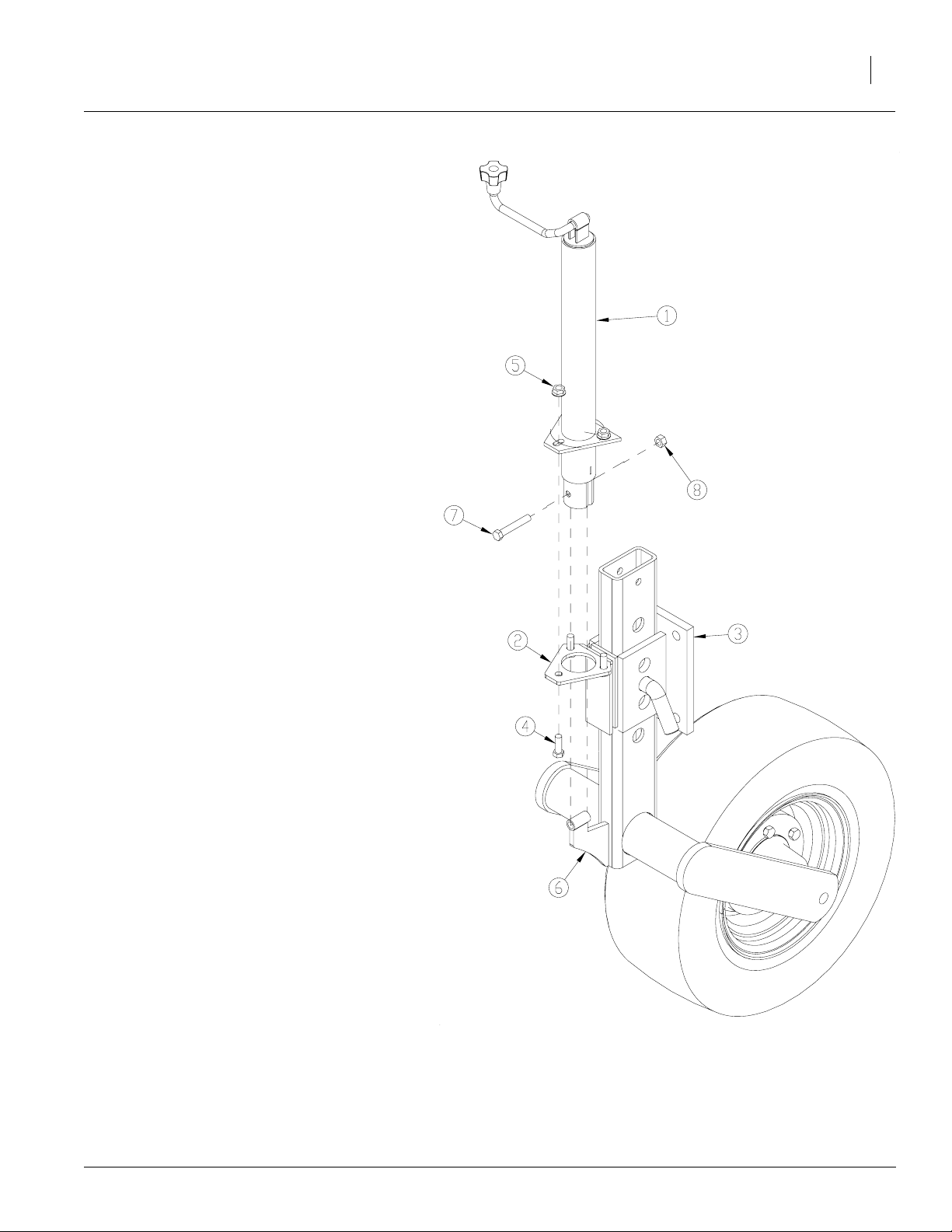
Refer to Figure 3
5. Assemble jack (1) by inserting jack through upper
jack mount plate (2) located on gauge wheel
mount (3). Secure plate (2) to jack (1) with three
7/16-14 x 1 1/4 bolts (4) and nut hex flange locs
(5).
6. Secure jack (1) to gauge wheel jack lower mount
(6) with 7/16-14 x 2 3/4 bolt (7) and nut hex lock
(8).
7. Repeat steps 5 and 6 on opposite side of inline
ripper frame.
NOTE: The jacks should only be used to help r aise
and lower the gauge wheels. The cross pin still needs
to be used in order to avoid overloading the jack.
Installation Instructions
3
5/4/2005
Figure 3
23177
596-158M
Page 4

Inline Ripper Gauge Wheel Jack Kit
4
Mounting the Jack on Gauge Wheels without 12"
Clearance
NOTE: There are two options f or mounting jacks to gauge
wheels without 12" clearance. Option 1 moves the gauge
wheels out towards the ends of the frame so they are not
lined up with the tractor tires or hitch. If you choose this option, move the gauge wheels and f ollow steps on page 2 listed under Mounting Jack on Gauge Wheels with 12"
Clearance. Option 2 mounts the gauge wheels on the back
side of the front frame tube as shown in Figure 4. If you
choose this option, follow the steps below.
Refer to Figure 4
1. Remove pin securing gauge wheel arm to gauge wheel
mount and remove gauge wheel and arm.
2. Unscrew U-bolts attaching gauge wheel mount to front
side of front frame tube. Keep parts for reuse .
3. Remove gauge wheel mount. Turn mount around so
gauge wheel can be mounted on back side of front
frame tube (3) as shown in Figure 4.
Great Plains Mfg., Inc.
4. Attach gauge mount (1) to back side of front frame tube
(3) with U-bolts (4) removed in step 1.Place gauge
wheel arm (2) on gauge wheel mount (1) and secure
with pin.
Figure 4
23179
596-158M 5/4/2005
Page 5

Great Plains Mfg., Inc.
Installation Instructions
5
Refer to Figure 5
5. Grind paint on bottom portion of back of the gauge
wheel arm (2).
6. Center and align gauge wheel jack lower mount (1) flush
with the bottom of the gauge wheel arm (2). Weld mount
(1) on arm (2).
7. Grind paint on the gauge wheel mount (3). Center and
align upper jack mount plate (4) flush with the bottom of
the gauge wheel mount (3). Weld plate (4) on gauge
wheel mount (3).
8. Repeat steps 5-7 on opposite side of inline ripper frame.
Paint new parts with Great Plains Green availab le from
the nearest authorized Great Plains dealer.
5/4/2005
Figure 5
23174
596-158M
Page 6

Inline Ripper Gauge Wheel Jack Kit
6
Refer to Figure 6
9. Assemble jack (1) by inserting jack (1)
through upper jack mount plate (2) located on
gauge wheel mount (3). Secure plate (2) to
jack (1) with three 7/16-14 x 1 1/4 bolts (4)
and nut hex flange locs (5).
10. Secure jack (1) to gauge wheel jack lower
mount (6) with 7/16-14 x 2 3/4 bolt (7) and nut
hex lock (8).
11. Repeat steps 9 and 10 on opposite side of inline ripper frame.
NOTE: The jacks should only be used to help
raise and lower the gauge wheels. The cross pin
still needs to be used in order to avoid ov erloading
the jack.
Great Plains Mfg., Inc.
Figure 6
596-158M 5/4/2005
23178
Page 7

Great Plains Mfg., Inc.
596-157A Inline Ripper Gauge Wheel Jack Kit
Your kit includes:
Qty. Part No. Part Description
2 596-159H GAUGE WHEEL JACK LOWER MOUNT WELD
2 596-232D UPPER JACK MOUNT PLATE
2 802-315C HHCS 7/16-14 x 2 3/4 GR5
6 802-673C HHCS 7/16-14 x 1 1/4 GR5
2 803-200C NUT HEX LOCK 7/16-14 PLT
6 803-229C NUT HEX FLANGE LOC 7/16-14 PLT
2 890-875C SCREW JACK 2000# TP-WND A-FRAM
Installation Instructions
7
596-158M5/4/2005
 Loading...