

Great Plains Mfg., Inc.
Installation Instructions
Application Systems
Hydraulic Meterflow Pump
Used with:
TA500 Sprayer
•
3P300 Sprayer
•
When you see this symbol, the subsequent instructions and
warnings are serious - follow without exception. Your life and
!
the lives of others depend on it!
General Information
These instructions explain how to install the hydraulic Meterflo w
pump. The pump is driven off the tractor hydraulics and pressurizes the sprayer contents for application.
These instructions apply to:
507-007A Pump TA Meterflow Hydraulic Assy
507-059A Pump 3-Point Meterflow Hydraulic Assy
Manual Update
Refer to the sprayer operator’s manual for detailed information
on safely operating, adjusting, troubleshooting and maintaining
the hydraulic Meterflow pump. Refer to the parts manual for part
identification.
• TA500 Sprayer Operator’s Manual. . . . . . . . . . . . .500-102M
• TA500 Sprayer Parts Manual. . . . . . . . . . . . . . . . . 500-061P
• 3P300 Sprayer Operator’s Manual. . . . . . . . . . . . .500-103M
• 3P300 Sprayer Parts Manual. . . . . . . . . . . . . . . . . 500-062P
Before You Start
Page 3 is a detailed listing of parts included in the hydraulic
Meterflow pump packages. Use these lists to in ventory parts received.
Assembly Instructions
Three-Point Spra y ers
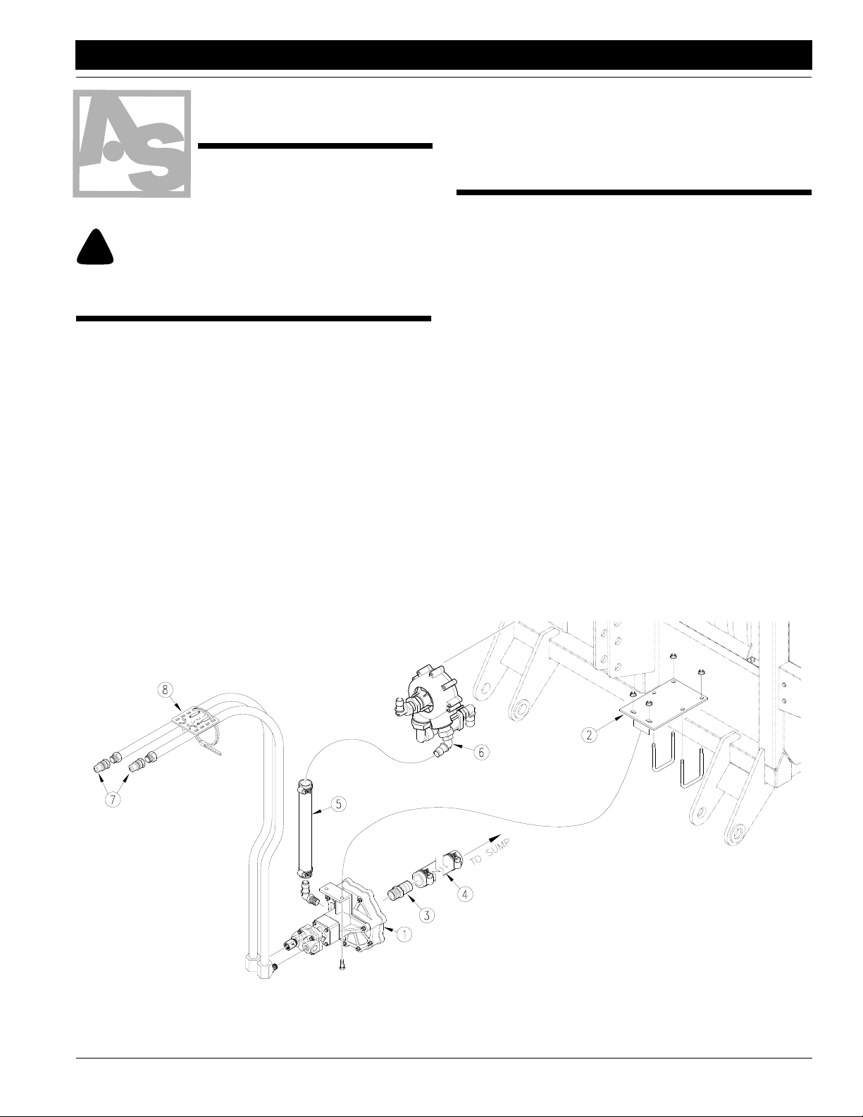
Refer to Figure 1.
1. Assemble hydraulic pump (1) to spra yer frame with plate (2)
and u-bolts as shown.
2. Screw adaptor (3) into pump inlet.
3. Using 1 1/2-inch hose (4) and larger worm clamps, connect
pump adaptor to hose barb on sump valve under sprayer
tank.
4. Using 1-inch hose (5) and smaller worm clamps, connect
Whirlfilter (6) to elbow outlet on pump.
5. Screw a coupler (7) on end of each hydraulic hose .
6. Assemble hydraulic hoses onto pump.
7. Using cable tie, secure hydraulic hoses in hose label (8)
about 18 inches from tractor quick couplers. Position label
so hose from port A is under retracted cylinder and hose
from port B is under extended cylinder.
© Copyright 1998 Printed 10/26/98
Figure 1
Three-Point Mounting
507-097M
16993
1
Assembly
Tandem-Axle Sprayers
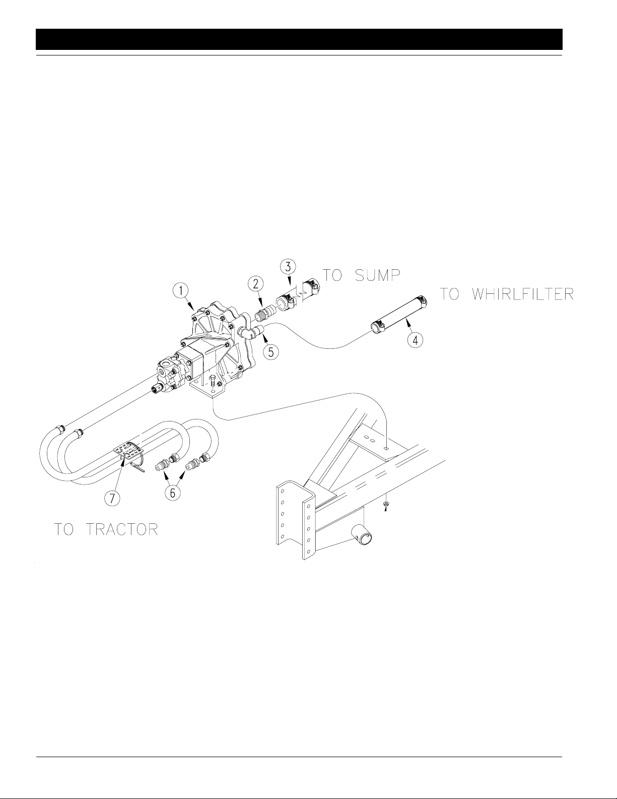
Refer to Figure 2.
1. Mount pump assembly (1) on spray er tongue using 3/8-inch
bolts and nuts provided.
2. Screw adaptor (2) into pump inlet.
3. Using 1 1/2-inch hose (3) and larger worm clamps, connect
pump adaptor to hose barb on sump valve under tank.
4. Using 1-inch hose (4) and smaller worm clamps, connect elbow adaptor on pump (5) to Whirlfilter.
5. Screw a coupler (6) on end of each hydraulic hose .
6. Assemble hydraulic hoses onto pump.
7. Using cable tie, secure both hoses in hose label (7). P osition
label so port A hose is under retracted cylinder and port B
hose is under extended cylinder .
Great Plains Mfg., Inc.
Figure 2
Tandem-Axle Installation
17387
Application Systems Hydraulic Meterflow Pump 507-097M 4/8/04
2
■

Great Plains Mfg., Inc.
Assembly
507-059A PUMP 3-POINT METERFLOW HYD ASSY
Your Kit Includes:
Qty. Part No. Part Description
1 507-013L PUMP METERFLOW - HYDRAULIC
1 507-029D 3-PT SPRAYER PUMP BRACKET
1 507-097M 3P/AS HYD PUMP ASSY MANUAL
2 800-123C CLAMP WRM DRV #16 SS (.68-1.5)
2 800-124C CLAMP WRM DRV #24 SS (1.06-2)
1 800-303C CABLE TIE 2 DIA MIN - BLK
2 802-079C HHCS 3/8-16X1 1/4 GR5
6 803-068C NUT HEX FLANGE 3/8-16 PLT
2 806-021C U-BOLT 3/8-16 X 3 1/32 X 4
1 810-247C VALVE, HYD PUMP CHECK
2 811-394C CP 3/4FORB MALE QD
2 811-500C HH1/2R2 050 3/4MORB 3/4MORB90
1 817-348C PLASTIC HOSE LABEL
1 830-092C AD 1 1/4MNPT X 1 1/2HB POLYP
1 990-079R HOSE 1 1/2ID EPDM SUCTION HOSE
1.25 990-082R HOSE 1 ID 200PSI EPDM
507-007A PUMP TA HYDRAULIC METERFLOW ASSY
Your Kit Includes:
Qty. Part No. Part Description
1 507-013L PUMP METERFLOW - HYDRAULIC
2 800-123C CLAMP WRM DRV #16 SS (.68-1
2 800-125C CLAMP WRM DRV#28 SS(1.31-2.
1 800-303C CABLE TIE 2 DIA MIN - BLK
2 802-022C HHCS 3/8-16X1 1/2 GR5
2 803-068C NUT HEX FLANGE 3/8-16 PLT
1 810-247C VALVE, HYD PUMP CHECK
2 811-160C HH1/2R1 050 3/4MORB
2 811-394C CP 3/4FORB MALE QD
1 817-348C PLASTIC HOSE LABEL
1 830-092C AD 1 1/4MNPT X 1 1/2HB POLY
4.667 990-079R HOSE 1 1/2ID EPDM SUCTION H
2.500 990-082R HOSE 1 ID 200PSI EPDM
4/8/04
Application Systems Hydraulic Meterflow Pump 507-097M
3
 Loading...