

Great Plains Mfg., Inc. Parts Installation Instructions 1
Two-Outlet Hydraulic Kit
2- and 3-Section Drills
Used with drill models:
• 2S-2600/F/HD/HDF
• 3S-3000/F/HD/HDF
• 3S-4000/F/HD/HDF
• 3S-5000/F/HD/HDF
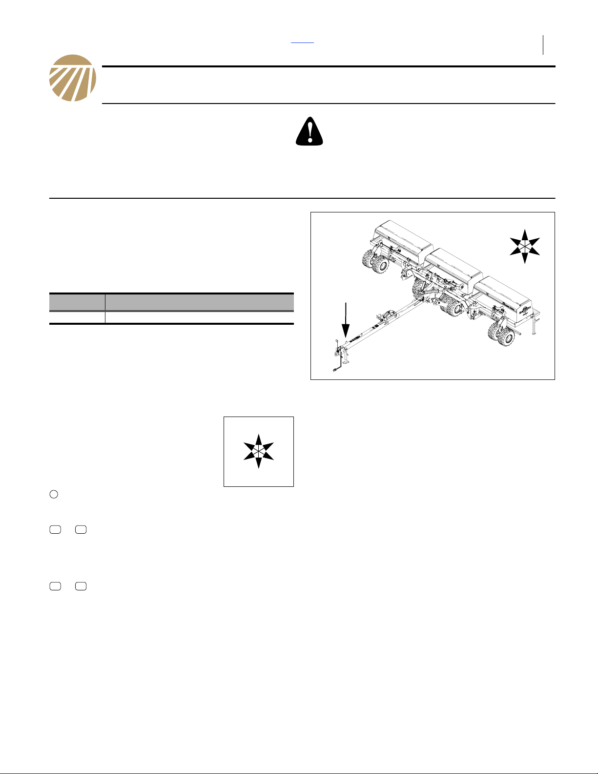
General Information
These instructions explain how to install the Two-Outlet
Hydraulic Kit. This combines the drill’s two Lift circuits
(Opener and Transport) into a single circuit at the hitch.
With this kit, a tractor having only two remotes can
operate a drill which would otherwise require three
circuits.
These instructions apply to:
Kit Kit Description
194-122A 3S TWO OUTLET TRACTOR HYD. KIT
This kit relies on some existing drill components.
This kit includes some parts not required, depending on
drill vintage, and drill options already present or also
being installed at this time.
If Markers are also to be installed, install the Two-Outlet
Hydraulic Kit first.
When you see this symbol, the subsequent instructions and
warnings are serious - follow without exception. Your life
and the lives of others depend on it!
U
R
F
B
L
D
Figure 1
Location of New Valve
15485
Notations and Conventions
“Left” and “Right” are facing in the
direction of machine travel. An
orientation rose in the line art
illustrations shows the directions of
Left, Right, Front, Back, Up, Down.
1
11 24
to
51 62
to
Each kit converts one drill.
single-digit or single-letter callouts identify
components in the currently referenced Figure
or Figures.
two-digit callouts in the range 11 through 24
reference new parts from the list on page 9.
The descriptions match those on the cartons,
bags or item tags, as well as in your updated
Parts Manual.
two-digit callouts in the range 51 through 62
reference affected existing parts from the table
on page 9. The descriptions match those in
your Parts Manual.
U
F
L
R
B
D
2014-04-15 ©Copyright 2014 194-033M

2 2-Outlet Selector Front Parts Great Plains Mfg., Inc.
Before You Start
Review these instructions, and make sure you
understand which existing system components are reused, and where they are located. The new components,
and the existing components to be re-used or discarded,
are located on the tongue of the drill, near the hitch.
Inventory the contents per “New Parts: Kit 194-122A”
on page 9.
Tools Required
• basic hand tools
• a tractor with two hydraulic circuits and suitable hitch
• liquid thread sealant
(for NPT fittings only - do not use PTFE tape)
• buckets for recovery of hydraulic oil from open hoses
These instructions presume a drill that has seen some
use, and may have pressure in the hydraulic system. The
installation may be done with the drill folded or unfolded.
Negative Tongue Weight Hazard:
If unfolded, the drill must be hitched to a tractor during
Opener Lift, to avoid negative tongue weight. Hitch loads can
range between +4000 pounds (folded) and -1000 pounds
(unfolded), depending on drill model and configuration.
Pre-Assembly Preparation
Inspect the Mounting Site
Refer to Figure 2
1. Examine the mounting site on the tongue. See if a
valve is already on the valve mount , and if any
hoses are under the clamps just aft of the mount.
2. Make sure the clamp hardware ( or ) is present.
It may be one of two different styles, depending on
the drill vintage. If there are no hoses under the
clamp, remove and save any: bolts, lock washers,
flat washers, clamp hold-downs, clamps and hose
guards.
If the drill does not have markers installed, a valve
mount welded on the tongue is available. The TwoOutlet selector valve mounts there, and includes a
bracket to provide a second mount point for another
valve.
If the drill already has markers installed, the valve mount
welded on the tongue already will already have a valve
mounted on it. You can mount the Two-Outlet selector
valve above it, or exchange their positions, using the
bracket in this kit.
1
1
A B
A
B
1
U
R
F
B
L
D
Figure 2
Valve Mount & Clamp
27023
194-033M Front Parts 2014-04-15
Great Plains Mfg., Inc. Front Parts Installation Instructions 3
Hydraulic Pressure Relief
High Pressure Fluid Hazard:
Only trained personnel should work on system hydraulics!
Escaping fluid under pressure can have sufficient pressure to
penetrate the skin, causing serious injury. Avoid the hazard by
relieving pressure before disconnecting hydraulic lines. Use a
piece of paper or cardboard, NOT BODY PARTS, to check for
leaks. Wear protective gloves and safety glasses or goggles
when working with hydraulic systems. If an accident occurs,
see a doctor immediately. Any fluid injected into the skin must
be surgically removed within a few hours or gangrene will
result.
Installation of this kit may require, at a later step, breaking
sealed hydraulic connections at quick-disconnect
couplers. It is crucial to safety that these lines be
depressurized.
3. If the available tractor has hydraulic circuits with
“float” capability, connect the Transport and Opener
Lift circuits, and relieve any residual system pressure
by floating the circuits.
If no suitable tractor is available, “crack” (carefully
loosen) the connections for both Lift circuits the at
the bleeding points specified in the drill Operator
manual. Leave them cracked for later bleeding.
Bleed only at:
JIC (Joint Industry Conference, 37° flare) or
NPT (National Pipe Thread, tapered) fittings.
Never bleed at:
ORB (O-Ring Boss) or
QD (Quick Disconnect) fittings.
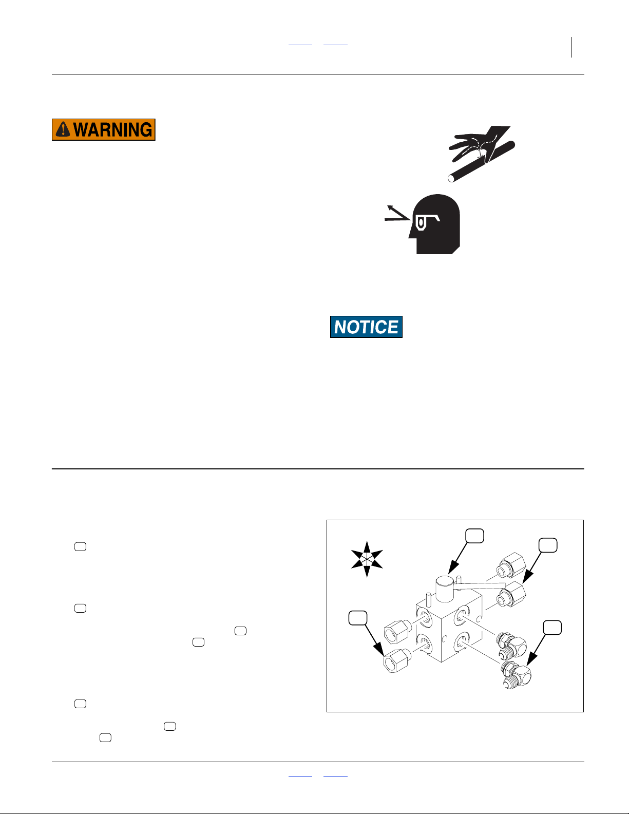
Assembly
Assemble Selector Valve
Note: Do not use thread sealant on ORB fittings.
Refer to Figure 3
4. Select: one new
19
810-274C DOUBLE SELECTOR VALVE 3/4FORB
The face openings of the valve are to machine left
after installation.
5. Select: two new
22
811-063C EL 3/4MJIC 3/4MORB
Install the ORB ends of the elbows in the face
(center) of the valve body (“1” and “2” are
stamped into the valve body at those ports). Before
tightening the jam nuts, orient the JIC ends so that
they face forward when the valve is mounted.
6. Select: four new
20
811-021C AD 1/2FNPTS 3/4MORB
Install the adaptors in the end ports of the valve
19
body (ports stamped “1A”, “1B”, “2A” and “2B”).
19
20
22
R
F
20
U
D
B
L
Valve and Fittings
Figure 3
19
20
22
27024
2014-04-15 Front Parts 194-033M

4 2-Outlet Selector Front Parts Great Plains Mfg., Inc.
Install Valve Mount
If markers are already installed, and a valve is already
present at the mount, skip to Step 8 on page 4.
Mount as First Valve
Refer to Figure 4
7. Select: one new
12
194-249D BRACKET, 2ND SELECTOR VALVE,
two new
16
802-168C HHCS 3/8-16X3 1/4 GR5,
and two new
18
803-013C NUT LOCK 3/8-16 PLT.
18
12
U
R
1
F
B
L
D
16
Position the valve assembly to the left of the
tongue valve mount , handle pointing to machine
left. Position the new bracket to the right of the
mount , with the bottom holes of the bracket
aligned with the mount holes.
Insert the screws through the valve, mount and
bracket. Secure with lock nuts .
1
1
16
2
12
18
Mount as Second Valve
Refer to Figure 5
(shown with hoses disconnected from existing valve for
clarity)
If markers are already installed, a valve is already
present on the tongue mount. The new valve mounts on
the bracket from the kit, but the old valve screws must be
removed to mount the bracket.
8. Select: one new
12
194-249D BRACKET, 2ND SELECTOR VALVE
Remove the existing nuts from the existing
screws and install the bracket . Align the
bottom holes of the new bracket with the screws.
9. Select: two new
16
and two new
18
Mount the new valve assembly on the left side of
the new bracket , above the existing valve .
Insert the screws from the left and secure with
lock nuts .
56 12
802-168C HHCS 3/8-16X3 1/4 GR5
803-013C NUT LOCK 3/8-16 PLT
12 1
16
18
57
1
2
2
Figure 4
Mount as First Valve
18
12
1
R
F
27025
U
B
L
D
16
57
56
2
Figure 5
Mount as Second Valve
Note: Although this sequence leaves the marker/fold
selector valve on the bottom, you may prefer to
have it on top (a more intuitive location, as the
markers are above the lift cylinders). The existing
valve may be moved, or you can change the hose
connections later (the valves are identical parts).
27026
194-033M Front Parts 2014-04-15

Great Plains Mfg., Inc. Front Parts Installation Instructions 5
Prepare New Hitch Hoses
Two circuits (Transport Lift and Opener Lift), which were
intended for direct connection to tractor remote ports, are
reconnected to the new selector valve starting at step 19.
Any Quick Disconnects (QDs) or hose handles on those
hoses are transferred or replaced.
The kit includes two new hitch hoses to the tractor. For
newer drills (with hose handles), continue at “2012+
Remove/Transfer Hose Handles”. For older drills
(without hose handles), continue at “2011- Remove/Add
Quick Disconnects” on page 6.
2012+ Remove/Transfer Hose Handles
10. Identify the two existing lift hoses.
• Transport Lift - Base End and Rod End
• Opener Lift - Base End and Rod End
23
Typically one set has blue hose handles and the
other red.
1
1
2
Verify that pressure is relieved, per step 3 on
page 3, in all four hoses.
Refer to Figure 6
11. Remove and save four sets of hose handle
bodies from both sets of existing lift hoses .
Save the blue handles. The red handles are not
reused.
Protect the exposed MORB-threaded hose ends
from contamination.
12. Remove four QD assemblies consisting of:
60
62
Do not disassemble these fittings.
Save one set of QD assemblies .
The other set is not reused.
13. Select: two new
23
Attach one QD assembly to each hose .
Re-assemble the blue hose handles on these hose
assemblies. Ensure that a no-icon handle half is on
each hose.
Continue at “2012+ Prepare Circuit Hoses” on page 6.
1 2
3
811-394C CP 3/4FORB MALE QD POPPET TYPE
811-919C AD 3/4MORB 3/4FORB (HG)
3
811-272C HH1/2R2 096 3/4MORB 3/4FJIC
323
62
3
60
Figure 6 2012+
2012+ Transfer Hose Handles
Note: Hose handles body halves are present in three
varieties (in addition to color):
• Extended cylinder icon
(upper left handle in Figure 6)
• Retracted cylinder icon
(upper right handle in Figure 6)
• No icon
(lower handles halves in Figure 6)
Note: If the existing hoses have a metal hose clamps or
plastic label with cylinder aspect icons, leave that
clamp or icon in place for future hose
identification.
34784
2014-04-15 Front Parts 194-033M

6 2-Outlet Selector Front Parts Great Plains Mfg., Inc.
2011- Remove/Add Quick Disconnects
If the drill lift circuits have hose handles, follow the steps
at “2012+ Remove/Transfer Hose Handles” on page 5.
The new hitch hoses provided in the kit are terminated
with MORB fittings. Older drills would have FNPT QDs.
The kit includes new FORB QDs.
Refer to Figure 7 (new hoses not shown)
61
2
2
61
2
23
61
24
24
24
Figure 7 2011-
Remove/Add Quick Disconnects
23
27023
14. Identify four hydraulic hoses for the following:
Transport Lift - Base End and Rod End
Opener Lift - Base End and Rod End
15. Remove the QD couplers or hose handles at
their FNPT threaded ends. They are not reused.
Protect the exposed NPT-threaded hose ends from
contamination.
16. Select: two new
23
811-272C HH1/2R2 096 3/4MORB 3/4FJIC
(96 inch hoses) and two new:
24
811-394C CP 3/4FORB MALE QD POPPET TYPE
Attach the two new QD couplers to the new
hoses .
If any blue cable ties or blue electrical tape is
available, use ties or tape to color-code the new
hoses near the QD end.
17. Continue at “Connect Lift Circuit Hoses” on
page 7.
23
2012+ Prepare Circuit Hoses
For older drills with MNPT-terminated lift hoses, continue
at “Connect Lift Circuit Hoses” on page 7.
Refer to Figure 8
18. Select: four new
21
811-023C AD 1/2MNPT 3/4FORB
Attach these adaptor to each existing lift hose .
2
21
2
Figure 8 2012+
Add MNPT-FORB Adaptors
36253
194-033M Front Parts 2014-04-15

Great Plains Mfg., Inc. Front Parts Installation Instructions 7
Connect Lift Circuit Hoses
Refer to Figure 9 (depicting 2012+ hoses - 2011- hoses are
MNPT-terminated without adaptors)
Note: Do not use thread sealant on JIC or ORB
connections.
Note: It may be necessary to loosen the FNPTS-MORB
adaptors on the valve in order to tighten hose
NPT connections without twisting the hoses.
Alternatively, hoses can be disconnected at
cylinder-end JIC connections.
19. Connect the Transport Lift hoses to the forward
valve ports (stamped “1B” and “2B”).
Connect the rod (retract) hose to the upper port
(stamped “1B”). Connect the base (extend) hose to
the lower port (stamped “2B”).
20. Connect the Opener Lift hoses to the aft valve
ports (stamped “1A” and “2A”).
20
B
A
R
F
U
D
B
B
L
A
20
Connect the rod (retract) hose to the upper port
(stamped “1A”). Connect the base (extend) hose to
the lower port (stamped “2A”).
21. Connect the new common Lift hoses to the
center (face) valve ports (stamped “1” and “2”).
Connect one hose to the upper port (stamped “1”).
Connect the other hose to the lower port
(stamped “2”).
22. Re-tighten any adaptor or cylinder JIC
connections loosed for these steps.
20
23
Figure 9
Connect Hoses to Valve
23
27027
2014-04-15 Front Parts 194-033M

8 2-Outlet Selector Front Parts Great Plains Mfg., Inc.
Secure Hoses
Refer to Figure 10
There are two or four hoses to clamp, requiring one or
two clamps. How to clamp them depends on the
available hardware. Figure 10 shows the recommended
stacking for four possible combinations.
The clamp components are:
13
196-146D 3-HOSE CLAMP BRACKET
14
196-885D HOSE CLAMP HOLDDOWN
15
802-010C HHCS 5/16-18X1 1/4 GR5
17
802-172C HHCS 5/16-18X2 1/2 GR5
51
1/4 MARKER HYD HOSE GUARD
52
HOSE CLAMP BRACKET
55
HHCS 5/16-18X1 1/4 GR5
58
WASHER LOCK SPRING 5/16 PLT
59
WASHER FLAT 5/16 USS PLT
23. Clamp new and any existing hoses. If markers are
yet to be installed, place the upper clamp hardware
in preparation for marker hoses.
Closeout
24. If no additional hydraulic options are to be installed
at this time, bleed the Lift systems per the
instructions in the drill Operator Manual. Follow
hitching instructions carefully, due to high positive
and negative hitch loads in various drill
configurations.
25. Confirm selector valve handle(s) forward is
Transport, handle(s) aft is Field, and all Extend/
Retract settings operate Base/Rod cylinder ends as
expected.
15
58
59
14
13
17
58
14
13
14
13
Figure 10
Hose Clamp Combinations
55
58
52
51
17
58
52
51
14
13
27030
194-033M Front Parts 2014-04-15

Great Plains Mfg., Inc. Front Parts Installation Instructions 9
Parts Lists
New Parts: Kit 194-122A
The part call-out numbers in this list match all Figures in
the installation instructions.
Callout Quantity Part Number Part Description
11 1
12 1
13 1
14 1
15 2
16 2
17 2
18 2
19 1
20 4
21 4
22 2
23 2
24 2
194-033M
194-249D
196-146D
196-885D
802-010C
802-168C
802-172C
803-013C
810-274C
811-021C
811-023C
811-063C
811-272C
811-394C
MANUAL TWO OUTLET HYD KIT
BRACKET, 2ND SELECTOR VALVE
3-HOSE CLAMP BRACKET
HOSE CLAMP HOLDDOWN
HHCS 5/16-18X1 1/4 GR5
HHCS 3/8-16X3 1/4 GR5
HHCS 5/16-18X2 1/2 GR5
NUT LOCK 3/8-16 PLT
DOUBLE SELECTOR VALVE 3/4FORB
AD 1/2FNPTS 3/4MORB
AD 1/2MNPT 3/4FORB
EL 3/4MJIC 3/4MORB
HH1/2R2 096 3/4MORB 3/4FJIC
CP 3/4FORB MALE QD POPPET TYPE
Your kit includes the following parts.
Existing Parts Affected
The following existing parts may be involved in the kit
installation. Which clamp bracket and fasteners are
present depends on drill vintage.The Disposition column
indicates whether parts are left in place, moved or not reused.
The part call-out numbers in the list match all Figures in
the installation instructions. Descriptions match those in
your drill Parts manual.
On an existing drill that has seen some use, and on
which markers have never been installed, the clamp may
be missing.
Part numbers are provided for ordering replacements.
The current bracket set is at left above, based on clamp
196-146D, which has replaced clamp 196-112D.
Quick Disconnects may vary from these parts.
Existing Parts List
Callout Part No. Part Description Part Disposition
51
52
53
54
55
56
57
58
59
60
61
62
113-370D
196-112D
196-146D
196-885D
802-010C
802-168C
803-013C
804-009C
804-010C
811-394C
811-856C
811-919C
1/4 MARKER HYD HOSE GUARD
HOSE CLAMP BRACKET
3-HOSE CLAMP BRACKET
HOSE CLAMP HOLDDOWN
HHCS 5/16-18X1 1/4 GR5
HHCS 3/8-16X3 1/4 GR5
NUT LOCK 3/8-16 PLT
WASHER LOCK SPRING 5/16 PLT
WASHER FLAT 5/16 USS PLT
CP 3/4FORB MALE QD POPPET TYPE
CP 1/2FNPT MALE QD
AD 3/4MORB 3/4FORB (HG)
Re-used unless no markers are present, and you use the
newer 196-146D clamp.
Re-used unless no markers are present, and you elect to
replace it with the newer 196-146D clamp.
Saved and re-used. Re-mount even if no use planned.
Saved and re-used. Re-mount even if no use planned.
Not re-used. Identical parts are provided in the kit.
Saved and re-used.
Saved and re-used.
Saved and re-used.
May be re-used.
If present, 2 of 4 are saved and re-used.
If present, not re-used.
If present, 2 of 4 are saved and re-used.
2014-04-15 Front Parts 194-033M

10 2-Outlet Selector Front Parts Great Plains Mfg., Inc.
Reference Information
Abbreviations Torque Values
AD Adaptor
CP Coupler
EL Elbow
GR Grade
HG Hose Grip
HH Hydraulic Hose
HHCS Hex Head Cap Screw (Bolt)
HYD Hydraulic
JIC
NPT (Female/Male) National Pipe Thread
NPTS NPT Swivel
ORB (Female/Male) O-Ring Boss
PLT Plated
QD Quick Disconnect
USS U.S. Standard
(Female/Male) Joint Industry Conference 37°
flare fittings
Fastener/Fitting Ft-Lbs N-m
3
⁄8-16 Grade 5 31 42
1
⁄2 NPT 11⁄2-3 turns past finger tight
5
⁄16-18 Grade 5 24 17
3
⁄4 JIC 27-39 37-53
Great Plains Manufacturing, Inc.
Corporate Office P.O. Box 5060
Salina, Kansas 67402-5060 USA
194-033M Front Parts 2014-04-15
 Loading...