

Great Plains Mfg., Inc.
Update Instructions
2N-24 & 2N-30 Drills
Hydraulic Depth Stop Update
Used with:
24’ and 30" Folding No-Till Drill
•
20 Series Folding Drill
•
When you see this symbol, the subsequent instructions
and warnings are serious - follow without exception. Your
!
life and the lives of others depend on it!
Before You Start
These update instructions provide information on how to modify
the 2N-24 and 2N-30 drills. These modifications will improve the
performance, reliability and/or safety of the original equipment. A
detailed Operator’s Manual was supplied with the main unit when
it was purchased. Refer to the Operator’s Manual for information
on safety, operation, adjustment, troubleshooting, and maintenance pertaining to this equipment (some of these sections do
not apply to all equipment).
A separate Parts Manual for replacement parts can be purchased from your dealer. Have model and serial numbers handy
when placing an order.
Manual Part Numbers:
• Folding No-Till Operator’s Manual . . . . . . . . . . . . .196-126M
• Folding No-Till Parts Manual . . . . . . . . . . . . . . . . . 196-126P
• 20 Series Folding Drill Operator’s Manual . . . . . . .196-164M
• 20 Series Folding Drill Parts Manual . . . . . . . . . . . 196-164P
General Information
These update instructions apply to the 2N-24 and 2N-30 Depth
Stops listed below:
196-189A 2SNT DEPTH STOP UPDATE KIT
Starting on page 4 is a detailed listing of parts included in these
kits. Use this list as a checklist to inventory parts received.
Instructions
The existing hydraulic depth stop valve is being upgraded. With
the new valve the coulter depth is adjusted by means of a knob
on the valve assembly (remove bushings before operation).
!
Escaping fluid under pressure can have sufficient force to penetrate the
skin. Check all hydraulic lines and hoses before applying pressure.
Fluid escaping from a very small hole can be almost invisible. Use paper or cardboard, not body parts, to check for suspected leaks. If injured, seek medical assistance from a doctor that is familiar with this
type of injury. Foreign fluids in the tissue must be surgically removed
within a few hours or gangrene will result.
IMPORTANT: When using sealant on pipe threads the friction
between the threads is reduced; therefore, be certain not to over
tighten which may cause damage to a valve, cylinder port or fitting.
Disassembly of Existing Depth Stop
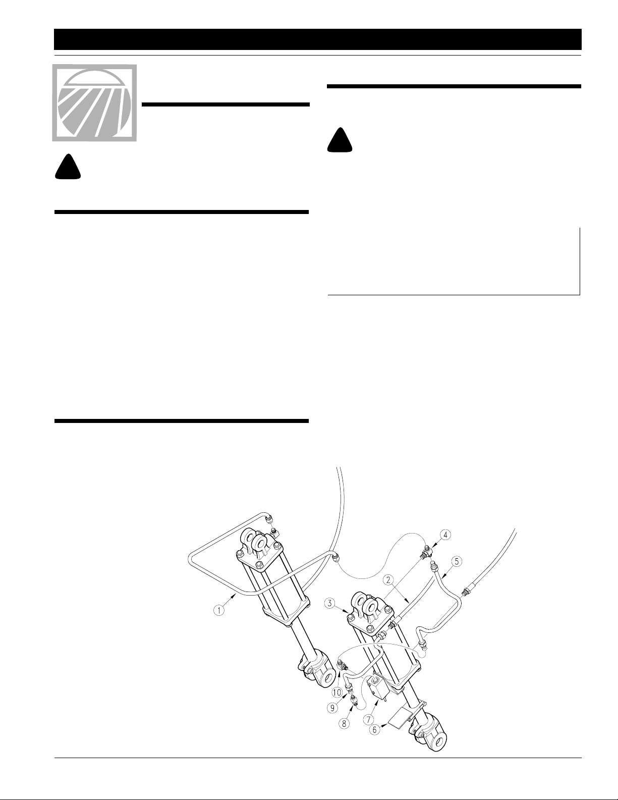
Refer to Figure 1:
With the drill attached to the tractor, unfold and lower the drill into
field position and relieve the cylinder pressure on the field lift cylinders . Remove the hard line (#1) and disconnect the hose (#2)
from the rod end of the left hand cylinder which the depth stop
valve is attached to. Unpin and remove the cylinder (#3). Remove and discard parts 4 through 10 from the cylinder.
CAUTION!
NOTE: JIC fittings do not require high torque. JIC and o-ring
fittings do not require sealant. Always use liquid pipe sealant
when adding or replacing pipe thread fittings. To avoid pos-
sible danger of cracking hydraulic fittings from overtighten-
ing, do not use plastic sealant tape.
© Copyright 1996 Printed 10/19/07
Disassembly
Figure 1
15662
196-188M
1
Assembly Instructions
Great Plains Mfg., Inc.
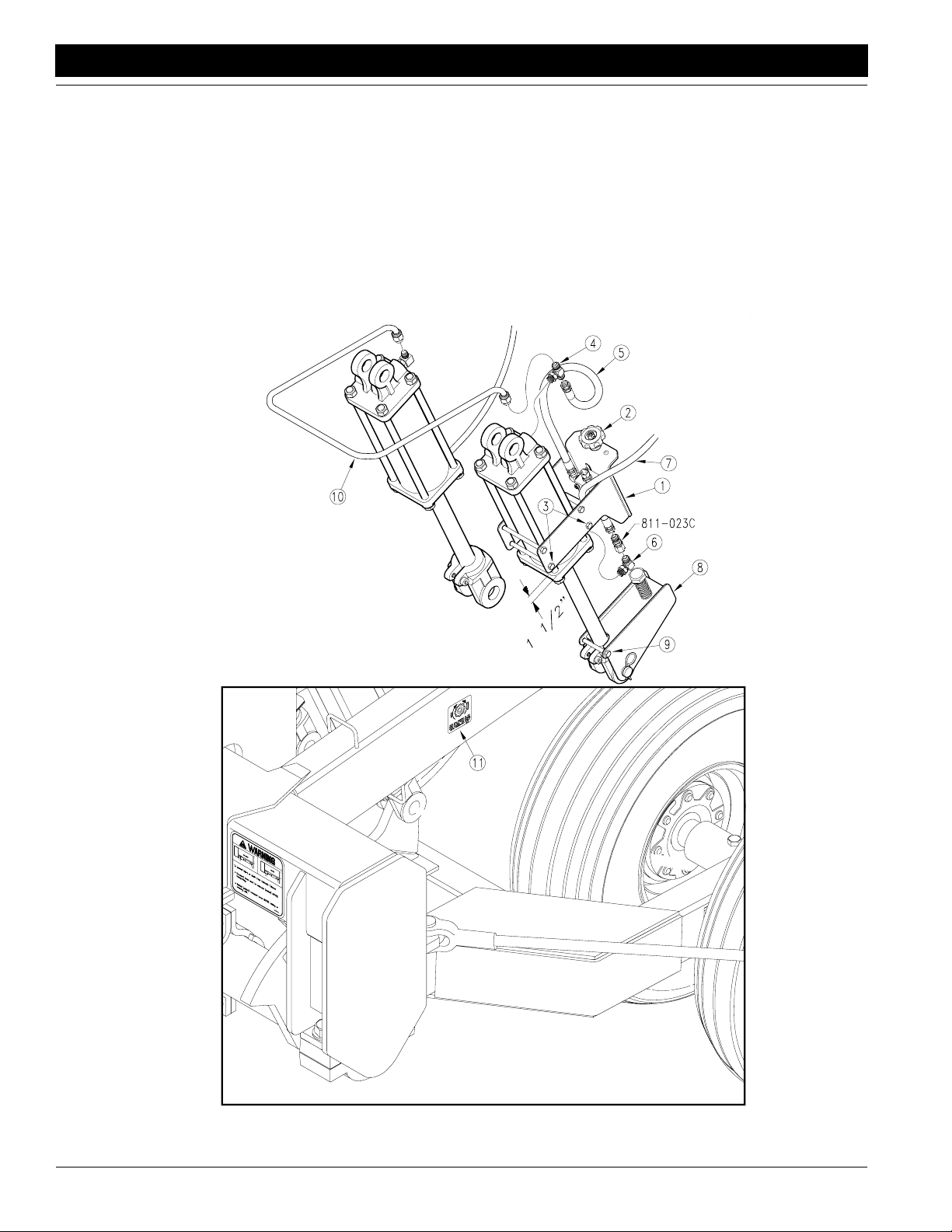
Depth Stop Assembly
Refer to Figure 2:
Torque the cylinder rod bolts to their proper settings. Install the
valve mount assembly (#1) over the cylinder body on the port
side. The plastic knob (#2) on the assembly must be installed in
the direction of the cylinder base. The assembly is held in place
with four 3/8" x 5 3/4" bolts (#3), 3/8" lock washers and 3/8" nuts,
locating it at the specified distance from the head cap (1 1/2"). Install the tee (#4) into the base end of the cylinder. Loop the 30"
hose (#5) which is attached to the valve assembly and install it
onto the tee (#4) at the cylinder base. Install the 3/4" o-ring x 3/
4" male jic elbow (#6) into the rod end port with the jic end pointing toward the base end. Insert the long hose (#7),from the base
end of the left hand gauge wheel cylinder through the mount and
attach it to the elbow (#6). Slip the clevis assembly (#8) over the
cylinder rod clevis and retain it in place with the 3/8" x 3 3/4" long
bolt (#9), 3/8" lock washer and 3/8" nut. Install and re-pin the
base end of this cylinder assembly back onto the main frame with
the valve side of the cylinder toward the drill boxes. The rod end
is to be repined through both the clevis assembly and the clevis.
Reattach the hard line (#10) between the fittings on the base end
of the lift cylinders. Apply the depth stop decal (#11) to the side of
the main frame tube where shown.
Depth Stop Assembly
Figure 2
2N-24 & 2N-30 Drills Hydraulic Depth Stop Update 196-188M 10/19/07
2
15663

Great Plains Mfg., Inc.
Assembly Instructions
Lifting System
Bleeding the Field Lift Hydraulics
This folding drill is equipped with rephasing type hydraulic
lift cylinders that require a special procedure for bleeding
air from the hydraulic system. If your dealer has not already prepared the cylinders for transport use, read the
following information carefully. The rephasing cylinders
will not function properly if this bleeding procedure is not
followed. Do not crack hose fittings in order to bleed air
from this system.
1. Put the tractor in park and activate its parking brake. If
the tractor does not have these features, block 2 or 3
of its wheels to positively prevent the tractor from roll
ing during this bleeding operation.
2. Back up and support the main frame and the outboard
ends of both boxes. Raise and support these 3 areas
just high enough to take the weight off of all four lift cyl
inders. If the gauge wheel cylinders have previously
been engaged, they may be used to assist in raising
the drill.
3. With the drill blocked and supported, unpin both ends
of all four wheel cylinders. Remove and safely position
the cylinders so the base end of the cylinder is lower
than the rod end port. Also, make sure there is enough
room for the rods of each cylinder to fully extend with
out contacting anything.
4. With the tractor at idle, hold the remote lever on to put
fluid into the lifting circuit. When the slave cylinders on
both wing drill boxes have completely extended, hold
the remote lever on for one minute.
5. Retract the cylinder rods. Extend the rods again and
hold the remote lever on for one more minute. Repeat
this step two more times to completely bleed the sys
tem.
6. Retract and reattach the hydraulic cylinders.
7. Add oil to the tractor’s hydraulic reservoir to fill it to the
proper level.
-
Operation
Coulter Depth Adjustments using the Coulter
Depth Control Valve
The "master-slave" field lift cylinders on your drill control the
-
depth of the coulters. A depth stop valve on the line which feeds
the base end of the master hydraulic cylinders, regulates the retracted length of these cylinders. One clockwise revolution of the
knob lowers the coulters approximately 3/32". Depth adjustments are best made with the drill slightly raised with the depth
stop engagement arm on the clevis end of the cylinder rod not
touching the valve. After adjusting the valve, raise and lower the
drill a few times and recheck the depth.
-
-
NOTE: In order to prevent trapped air pockets, the
port on the rod end must be higher than any other
part of the cylinder during the bleeding operation.
10/19/07
2N-24 & 2N-30 Drills Hydraulic Depth Stop Update 196-188M
3

Great Plains Mfg., Inc.
Listing of Parts
196-189A 2SNT DEPTH STOP UPDATE KIT
Your Kit Includes:
Qty. Part No. Part Description
1 196-187K 2SNT DEPTH STOP VALVE ASSY
1 196-188M MANUAL 2SNT DEPTH STOP UPDATE KIT
1 196-190K 2SNT DEPTH STOP CLEVIS ASSY
1 802-026C HHCS 3/8-16X3 3/4 GR5
4 802-616C HHCS 3/8-16X5 3/4 GR5
5 803-014C NUT HEX 3/8-16 PLT
5 804-013C WASHER LOCK SPRING 3/8 PLT
1 811-023C AD 1/2MNPT 3/4FORB
1 811-077C TE 3/4MORB 3/4MJIC 3/4MJIC
1 811-280C EL 1/2FNPT 3/4MORB
1 811-324C AD 3/4MORB 3/4FJIC
1 818-748C DECAL 2SNT DEPTH STOP
10/19/07
2N-24 & 2N-30 Drills Hydraulic Depth Stop Update 196-188M
4
 Loading...