

Great Plains Hyd Hose Route User Manual

Great Plains Mfg., Inc.
Installation Instructions
30’ No-Till Drill (Oct. 2004 and before)
Hyd. Hose Route Update
Used with:
• 3N-3010P
• 3N-3020P
• 3N-3010
• 3N-3020
General Information
When you see this symbol, the subsequent instructions and
warnings are serious - follow without exception. Your life and
!
!
the lives of others depend on it!
These instructions explain how to install the wing hydraulic hose route update kit. Hose routing hardware
for hoses going to the left-hand and right-hand wings.
Fits any 30’ production drill built prior to Nov. 2004.
These instructions apply to:
196-415A 30P Wing Hyd. Hose Route Update.
Manual Update
Refer to the 30’ No-Till Drill operator’ s manual f or detailed information on safely operating, adjusting,
troubleshooting and maintaining the 30’ No-Till Drill.
Refer to the parts manual for part identification.
196-2448M Operator’s Man ual
196-248P Parts Manual
196-366M Operator’s Man ual
196-366P Parts Manual
Assembly Instructions
Refer to Figure 1
1. With the drill unfolded and working on the lefthand side of the drill, place the center left-hand
hose guide on top of the center frame.
Before You Start
Page 3 is a detailed listing of parts included in the 30P
Hyd. Hose Route Update Kit package. Use this list to
inventory parts received.
T ools Required
• Basic hand tools
Definitions
Right-hand and left-hand as used in this manual are
determined by facing the direction the machine will
travel while in use unless otherwise stated.
Hose Clip
2. Hold in place with a 3/8" x 1 1/2" bolt (not visible
under hoses in picture). Insert bolt through the
cylinder lock storage hole. Add a 3/8" lock w asher
and 3/8" nut and tighten.
3. Route hoses through the wire ring and place on
top of the hose guide. Hold hoses in place with
the hydraulic hose clip , 3/8" x 1" bolts , 3/8" lock
washers and 3/8" flat washers.
© Copyright 2004 Printed
11/09/2004
Hose Guide
Figure 1
22776
196-416M
Hyd. Hose Route Update
2
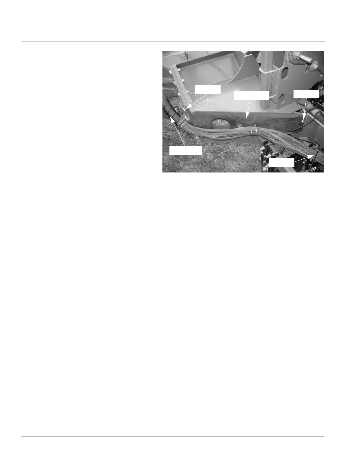
Refer to Figure 2
4. Remove the two 3/4" bolts from the outside of
the pivot pin support cap weldment.
5. Attach one of the wing hose guides to the
wing frame using the two 3/4" bolts removed
in the previous step.
6. Attach the slotted end to the frame using two
1/4" x 1 1/2" bolts, 1/4" flat washers and 1/4"
lock nuts.
NOTE: If a monitor is mounted on the wing frame
it will be necessary to loosen the bolts holding the
monitor and slid the hose guide under the monitor.
Leave the monitor loose. This m ust be done before installing the 3/4" bolts. After tightening the
3/4" bolts retighten the bolts holding the monitor.
7. Route hoses through the wire rings.
NOTE: It ma y be necessary to loosen the hoses at
the gauge wheel cylinders to remove any twists in
the hoses.
8. Repeat all steps to install the hose guides to
the right-hand side of the drill.
Hose Wrap
3/4" Bolt
Hose Guide
Figure 2
Great Plains Mfg., Inc.
1/4" Bolt
Wire Tie
22777
9. Use the plastic wire ties to group the hoses together. Place the spiral hose wr ap around the
hose at the pivot point between the center
frame and wing frame.
196-416M 11/29/
 Loading...