

Page 1
Operator Manual
Models FF and HD
Martens Brand Harrows,
Vintage 2010 and Prior
Manufacturing, Inc.
www.greatplainsmfg.com
Legacy manual provided for owners and users of these model harrows
not manufactured by Great Plains Manufacturing, Inc. For continuing
support and parts of older implements, contact Great Plains.
© Copyright 2010 Printed 11/29/2010 564-000M
EN
Page 2

Martens Harrow Quick Start Guide
Avoid Damage to your harrow!
Please Read
This Page!
Please read the owners manual, but here are some important
items for you to know to avoid damage to your harrow.
1. Securely attach hitch to tractor Page 3
2. To avoid wing and cylinder damage - extend all cylinders
completely before working in the field. Page 5
3. Do not partially lift harrow for turning or extended periods
while working in the field. Page 5
4. Do not move the machine until wings are fully unfolded or
refolded. Page 4 & 6
5. Fold and unfold wings slowly Page 4 & 6
6. Never back up with the harrow sections on the ground.
Page 5
7. Do not turn so short as to make the wing wheel go
backward. Page 5
8. If the wings do not slide onto the steady rest easily, the
height needs to be adjusted. Page 8
In the manual, we have our safety warnings and operational
warnings to be in bold italic lettering for you to better recognize
these items.
2
Page 3
OPERATING INSTRUCTIONS FOR MARTENS FRONT
FOLD HARROWS
Unfold to field position.
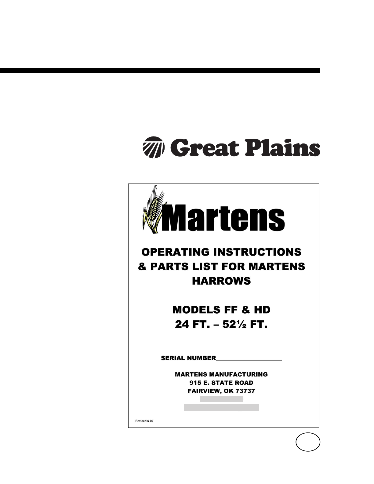
1. Attach tongue of harrow securely to the towing tractor using sufficient drawbar pin.
Connect cleaned hydraulic couplers of harrow to tractor. Raise jack and swing to
horizontal position WARNING: Make certain harrow is securely attached to the
towing tractor. Tip-over may occur during unfolding if harrow comes loose from
tractor.
2. Disconnect transport safety chains from wing.
3
Page 4
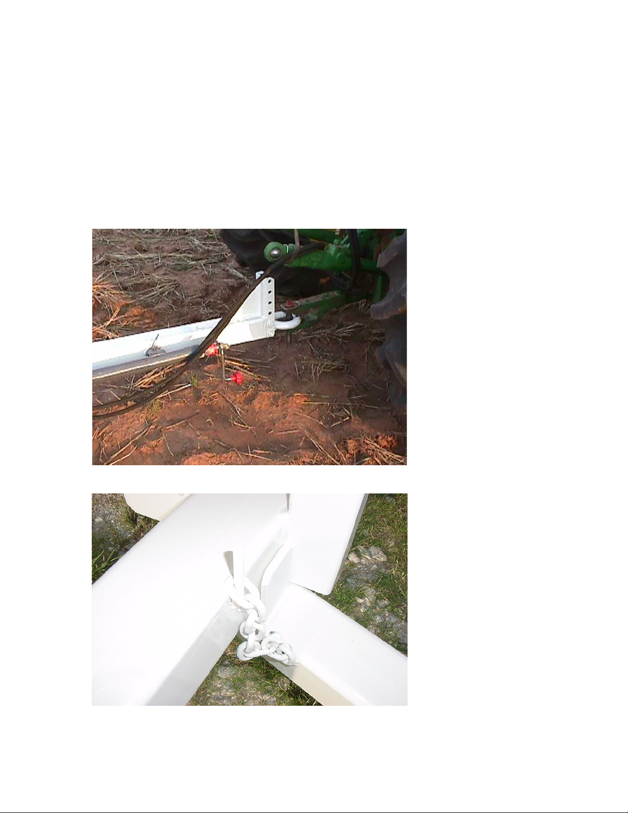
3.Make certain area around harrow and behind harrow is clear of people and obstacles. With
engine speed at low RPM, slowly operate hydraulic lever to swing wings back until the wings
are unfolded. Do not move the harrow until the wings are fully unfolded. WARNING: Do
not walk or allow others to walk behind harrow when it is in the unfolded vertical position.
Hydraulic malfunctions or the hitch pin coming loose could allow the harrow to tip over
causing serious injury.
4.When the wings are unfolded, the sections will start to be lowered to the ground. When the
rear bars of the sections start to touch the ground, start driving forward slowly.
4
Page 5
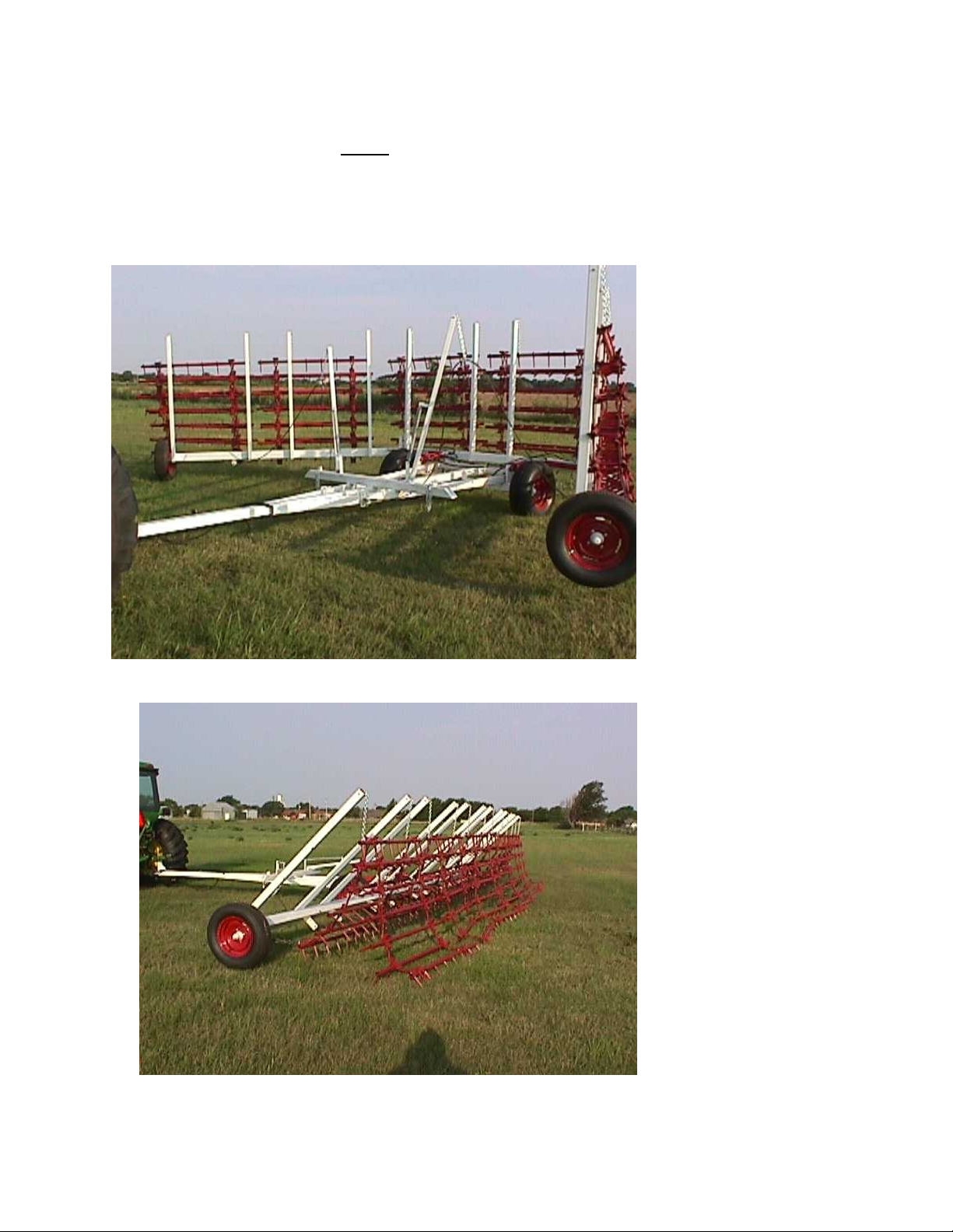
5. Continue lowering sections until they lie flat on the ground.
6.
IMPORTANT -
hydraulic lever to fully extend the wing cylinder so the cylinder pin is approximately in the
center of the slot. This allows up and down travel for the wing over rough ground.
When the sections are on the ground, continue to operate the
I OR
Failure to fully extend cylinder will damage the cylinder or the
framework.
7. Harrow is ready for field use.
WARNING: This harrow is designed to be pulled in the field with the harrows fully on
the ground and all cylinders fully extended at all times. Pulling the machine with the
sections lifted off the ground over extended distances or lifting the harrows off the ground
for turning at corners or end of rows is not recommended and will result in premature
wear of the cylinders, pins, and frame components and those parts will not be warrantied.
Lifting the harrow for a short distance to unplug any residue clog is acceptable. Never
back up with the harrow sections on the ground. Always lift the sections off the ground
before backing up. Do not turn so short as to make the wing wheel roll backward.
5
Page 6

Refolding the Harrow to Transport Position
1.
Do not move the machine until wings are fully folded to transport position. With engine
running at low RPM, slowly operate the hydraulic lever to raise the sections to vertical.
WARNING: Do not walk or allow others to walk behind harrow when it is in the unfolded
vertical position. Hydraulic malfunctions or the hitch pin coming loose could allow the
harrow to tip over causing serious injury.
Do not move
n t v
the machine
until wings
are fully
folded. Wing
o
frame damage
may occur.
2. As the wings start to fold inward, make certain that the spring operated cable lift arms are
lifting the cables. If the cable arms are not lifting properly, they will be damaged by the
wings. NOTE: Harrows smaller than 30 ft. do not use cables.
a n
n
n until wings
l
l are fully
W
W folded. Wing
r center
u
6
Page 7

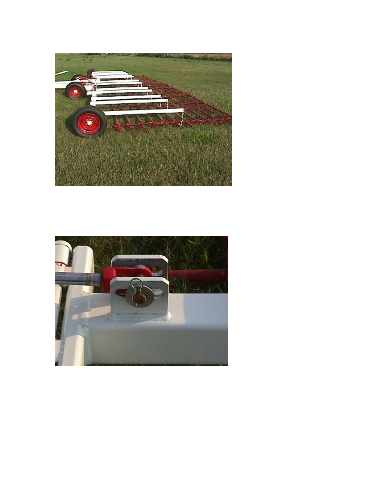
3. Operate the hydraulic lever until the wings are fully against the stop on their support and hook
the transport safety chains to the wings for safe transport. Machine can now be moved.
Maintenance and Adjustment Instructions.
Greasing – Every day.
zerks on pivot pins – 8 zerks on wing pins
6
7
Page 8

Adjusting wing fold height –
Figure A
Figure D
Figure E
As pins wear and settle in, wings may droop a bit and need adjustment to make the wings slide
up the ramp to the wing support crossmember. This is adjusted by turning the stop screw on the
lift cylinder as shown. (All FF model 12 bar harrows smaller than 43 ½ ft. use figure A)(HD 12
& 16 bar harrows up to 43 ½ ft. wide use a bolt stop as in figure C.)(All harrows 45 ft. and up
use a shim stop as in figure D & E. Shims are added to raise the wing.) The stop screw should be
adjusted so the wing engages about ½ ” below the top of the ramp as shown in figure B. Silicone
sealer should be spread across the threads to prevent the stop screw from moving. NOTE:
Harrows smaller than 30 ft. do not use wing adjustment or wing support crossmember.
Figure B
Figure C
8
Page 9

Tooth Angle Adjustment –
The teeth can be pulled at either a 40 or 22 degree (back from vertical) angle depending upon the
aggressiveness and soil stirring action needed. If the harrow is pulled with the long side of the
restrictor bracket toward the front of the harrow, it is set at 40 degrees back of vertical (flatter
and most commonly used tooth angle – factory setting). If the short side of the restrictor bracket
is to the front of the harrow, the setting is 22 degrees back of vertical (straighter up and down –
more aggressive). To change the setting, the harrow sections must be unhooked from the frame,
reattached and pulled from the other end of the section. Harrows come from the factory set at 40
degrees and most people use them that way in most conditions.
22
40
In most conditions the 40 degree setting (flatter) is preferred. It will give a
better seedbed and will flow residue more easily.
If you use the harrow in the 22 degree setting, you must slow down to 4 ½
mph. The aggressiveness of the tooth in the straighter up and down position is
much harder on the machine and the section will hop if the speed is too fast.
Residue flow will be much better in dry conditions. Wet residue has a
tendency to ball up.
9
Page 10

Martens Harrow Parts List
Harrow Size, Year Model, and Serial Number Identification
Your harrow will have a Model, Serial Number and Size Tag on the top of the tongue near the
front of the machine. There is also a serial number and size stanped into the top of the tongue
near the front of the machine. The serial number is the same as the date built. Example – SN
071205 would have been built on July 12, 2005. Model designations are FF- Standard Frame 8 or
12 bar. HD – Heavy Duty Frame 8, 12, or 16 bar.
Flex Harrow Section Parts –
The FF and the HD harrows use the same 4 bar sections that are bolted together to make 8, 12, or
16 bar harrows.
Ordering Harrow Bar Pipes
To order harrow pipes, we must know the following info:
*What is the length of the pipe? 48”, 66”, or 84”
*Counting from the front of the harrow section as it lays on the ground, what number pipe is it?
This is important because the pipes are drilled with different spacing.
*What is the size of the harrow?
* Which section is it? End wing, inside wing, center wing?
* Does the pipe have a 12” extension pipe bolted into the end of the pipe.
48” Pipe for 4
½ ft. Section
12” Extension
Pipe
84” Pipe for 7
½ ft. Section
66” Pipe for 6
ft. Section
Notice –
Pipes are
drilled with
different
spacing.
Counting
from the
front, you will
need to know
what number
pipe it is and
the length of
the pipe.
10
Page 11

Ordering Flex Harrow Section Parts
Tooth – 6”
U Pull Clamp 301522
Angle Stop
Plate 301557
Pull Tab 302007
Bow Tie Link
- 302014
Hub Identification
8 Bolt Hub - # 8BH100 – Used on HD Main Axle
6 Bolt Hub - #6BH101 – Used on FF Main Axle
4 Bolt Hub - #4BH102 – Used on FF and HD Wing Spindle
Spindles are weld-in units – Call factory for assistance
Cylinder Identification
3 ½ X 8 – #35X8 - FF Main Lift Cylinders
3 ½ X 16 - #35X16 – HD Main Lift Cylinders 22 ½ ft. through 43 ½ ft.
4 X 16 - #40X16 – HD Main Lift Cylinders 45 ft. through 52 ½ ft.
2X14 - #20X14 – FF & HD Wing Cylinders 22 ½ ft. through 28 ½ ft.
2 ½ X 14 - #25X14 – FF & HD Wing Cylinders 30 ft. through 43 ½ ft.
3 X 14 - #30X14 – HD Wing Cylinders 45 through 52 ½ ft.
11
Page 12

Parts List –
September 20, 2009
Main Description Sub-description Part Number Notes
Clevis Hitch Clevis Hitch Clevis Hitch Specify if FF or
HD model
4 Bolt Hub Complete with bearings,
races, seal & cap
Large Wheel Bearing and
race
Small Wheel bearing and
race
Hub Seal 16069
6 Bolt Hub Complete with bearings,
races, seal & cap
Large Wheel bearing and
race
Small Wheel bearing and
race
Hub seal SL162
8 Bolt Hub Complete with bearings,
races, seal & cap
Large wheel bearing and race LM603049,
Small wheel bearing and race LM67048,
Hub seal SL226
Wheel bolts 4 bolt ½-20 Bolt
Wheel Nuts 6 bolt ½-20 Nut
8 bolt 9/16-18 Nut
Wheel 4 hole 15” 4WH15
6 hole 15” X 8” 6WH15
8 Hole 15” X 10” 8WH15
15” Aircraft Tire & 4 or 6
bolt wheel
Harrow Teeth 6” tooth Tooth
½” Top Lock Nut Nut
Wing Cable 3 section (11’10”) Cable 4 Sec
5&6 section (15’2”) Cable 6 Sec
7 &8 section (17’10”) Cable 8 Sec
4BH102
LM67048,
LM67010
LM11949,
LM11910
6BH101
JL69349,
JL69310
LM67048,
LM67010
8BH100
LM603011
LM67010
4ACWH15
12
Page 13

Cable Lift Arm Cable Lift Arm Cable Lift Arm Specify Harrow
Size
Cable Lift Spring CLS
Cable Lift Clevis 3/8Clevis
Harrow Bar Pipes 48” Pipe 4 ½’ Pipe-
1,2,3,4
66” Pipe 6’ Pipe – 1,2,3,4 Must specify
84” Pipe 7 ½’ Pipe-
1,2,3,4
93” Pipe 8’3” Pipe –
1,2,3,4
12” Extension EXT9 9” between holes
Cylinders See cylinder
Flex Section Parts U Pull clamp 301522
Angle Stop Plate 301557
Pull Tab 302007
Bow Tie Link 302014
Pull & Lift Chains FF Pull Chain Complete FFPC
HD Pull Chain complete HDPC
Section Lift Chain FF&HD SLC
Hoses 58” X 3/8 Hoses Hose58
27’ X 3/8 Hoses Hose27
31’ X 3/8 Hoses Hose31 For 45’ and
Must specify
which pipe
which pipe
Must specify
which pipe
Must specify
which pipe
identification
chart.
larger
Martens Model HD & FF Harrow Warranty Policy
Martens Manufacturing warrants to the original owner that within two years from the date of purchase, any part of
the harrow frame, or within one year any part of the harrow sections should fail due to defect in material or
workmanship, Martens Mfg. will, at their discretion, repair or replace it free of charge. Damage, failure, or wear due
to improper operation will not be warranted. Due to many varying operating conditions and methods, there is no
warranty on bent or broken section pipes.
Warranty service is available by contacting your Martens dealership.
Martens policy is to constantly improve its products. The right is reserved to make changes in design and pricing
without incurring any obligation to incorporate such improvements in any product which has been shipped or is in
service.
13
Page 14

Great Plains Manufacturing, Inc.
Corporate Office: P.O. Box 5060
Salina, Kansas 67402-5060 USA
 Loading...