

Page 1
Great Plains Mfg., Inc.
Installation Instructions 1
Ground Drive Fertilizer Pump
Yield Pro Planters
Used with:
• 2006- Yield Pro
® 1225/1625
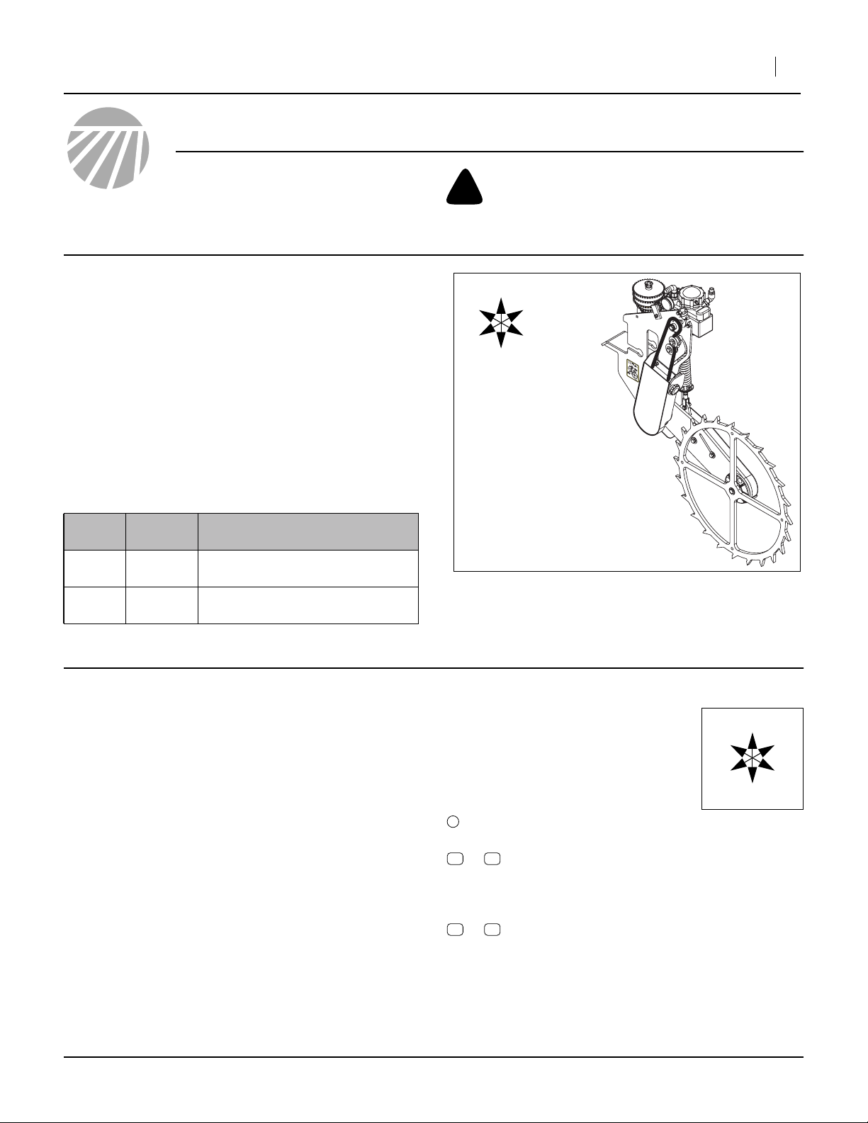
General Information
These instructions explain how to install the Ground
Drive Fertilizer Pump enhancement kit on a planter
which already has a fertilizer pump coupled to the meter
drive system. Installing this kit eliminates the need to
adjust the pump whenever seed rates are changed.
This kit is not needed for 2007+ planters, as their
optional fertilizer systems already include these components. This kit requires a pre-existing fertilizer system,
and re-uses many existing system components.
These instructions apply to:
Planter
Model
YP1225 407-148A YP GROUND DRIVE FERT
YP1625 407-148A YP GROUND DRIVE FERT
Kit Kit Description
PUMP KIT
PUMP KIT
When you see this symbol, the subsequent instructions
and warnings are serious - follow without exception.
!
Your life and the lives of others depend on it!
U
F
L
R
B
D
Figure 1
New Ground Drive Assembly
25302
Before You Start
Each kit converts an entire planter. Inventory the contents per “New Parts: Kit 407-148A” on page 7.
Review these instructions, and make sure you understand which existing system components are re-used,
and where they are located. The new components, and
the existing components to be re-used or discarded, are
located on the back of the left wing of the planter, about
halfway out on the toolbar.
Tools Required
• pipe sealant such as RECTORSEAL® NO. 21
• basic hand tools
• a second or third person for Step 28
Notations and Conventions
“Left” and “Right” are facing in the
direction of machine travel. An orientation rose in the line art illustrations
shows the directions of Left, Right,
Front, Back, Up, Down.
1
11 27
to
51 71
to
callouts identify components in the currently
referenced Figure or Figures.
callouts reference new parts from the list on
page 7. The descriptions match those on the
cartons, bags or item tags, as well as your
updated Parts Manual.
callouts reference affected existing parts from
the table on page 9. The descriptions match
those in your Parts Manual.
U
F
L
R
B
D
©Copyright 2006 Printed 04/23/2007 407-149M
Page 2
2 Ground Drive Fertilizer Pump
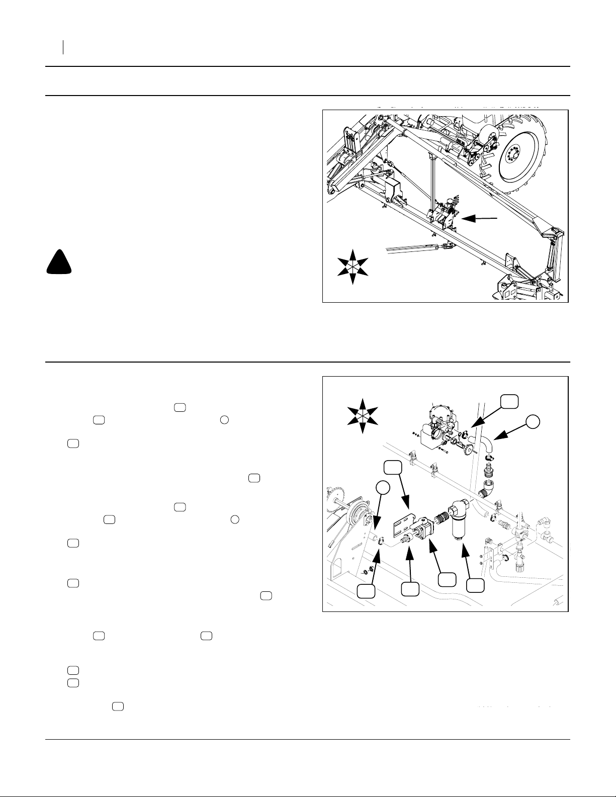
Pre-Assembly Preparation
Refer to Figure 2,
which depicts the planter with row units removed for clarity.
The ground drive pump is installed on the left wing,
at or near the location of the existing shaft-driven
fertilizer pump.
1. Unfold the planter. The planter must be raised for
unfolding, but may be raised or lowered for all
tasks prior to Step 28. If left raised, installed lift/
transport locks. Secure the tractor.
2. Flush the existing fertilizer system with water. Fluids will drain off during updates to the plumbing.
!
CAUTION
Exercise caution when working with a used fertilizer system.
The chemicals are usually very caustic. Unless you fully
operate the planter while flushing with water, some chemicals
will drain from components during disassembly. Trace
amounts may remain in any case.
R
F
U
D
B
L
Figure 2
Location of Components
Great Plains Mfg., Inc.
25303
Remove Existing Components
Dismount Valve and Strainer
Refer to Figure 3
3. Loosen the hose clamp on the inlet port of
67 1
valve and disconnect the hose .
Remove and save:
56
CLAMP WRM DRV #16 SS (.68-1.5)
If the hose can reach the ground, protect the open
end from contamination, for example, by clamping
a plastic bag over the end. If the strainer is due
for maintenance, this is an ideal time to clean it.
4. Loosen the hose clamp on the outlet port of
strainer and disconnect the hose .
Remove and save:
56
Protect hose end from contamination.
5. Remove:
69
plastic adaptor fitting from the inlet of valve .
This fitting is not re-used.
6. Remove the fasteners (not shown) that attach
valve to valve mount plate , and that attach
the plate to the planter frame.
Remove and save the valve/strainer assembly:
70
67
and its interconnecting and outlet fittings.
The plate and the fasteners are not re-used.
70 2
CLAMP WRM DRV #16 SS (.68-1.5).
AD 1 1/2MNPT X 1HB POLYPROP
67 52
STRAINER BANJO LST150-80 MESH
VALVE 1 1/2FNPT BALL POLYPROP
52
56
70
56
67
R
F
U
D
56
B
L
52
1
69
Dismount Strainer
67
Figure 3
56
2
70
25304
407-149M 04/23/2007
Page 3
Great Plains Mfg., Inc.
Installation Instructions 3
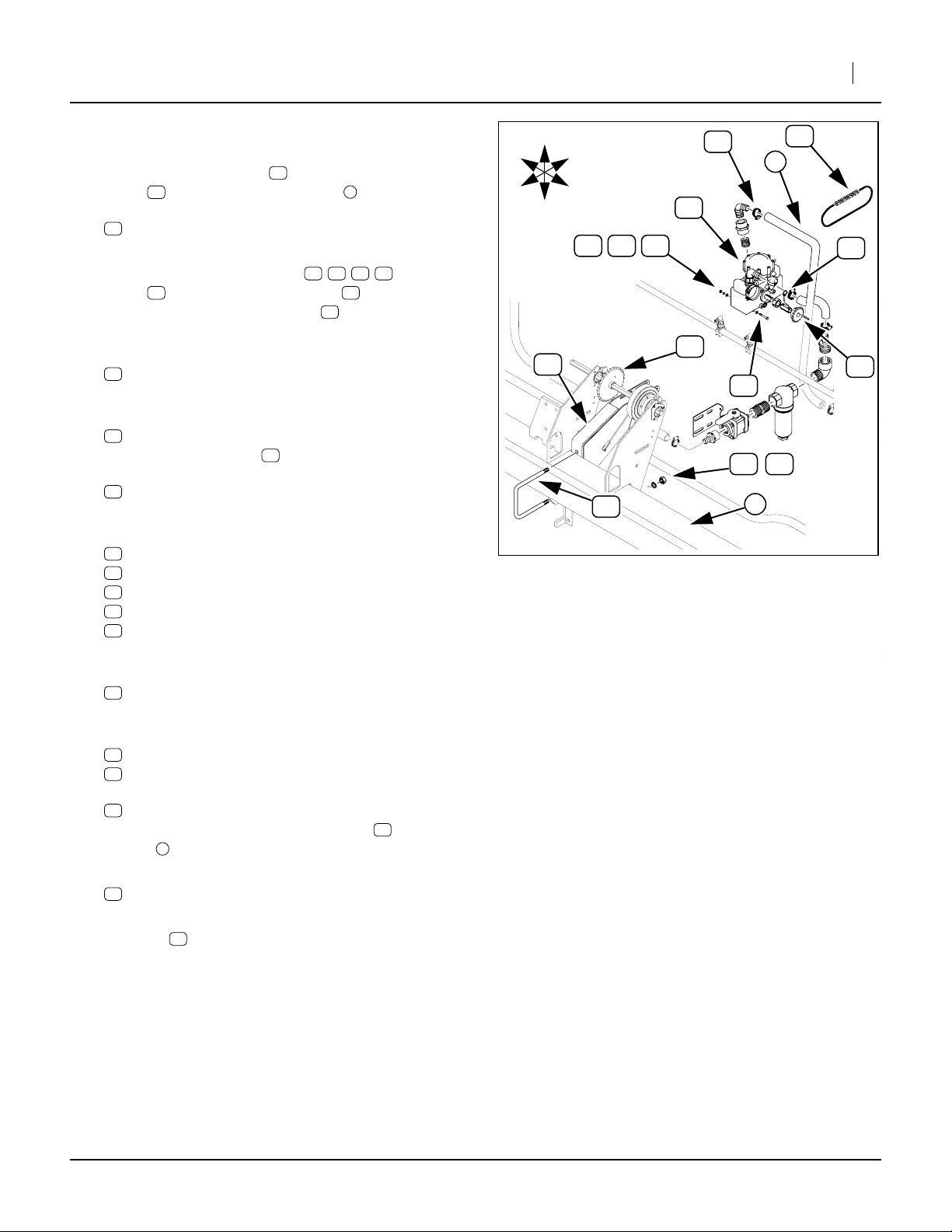
Dismount Pump and Pump Sprocket
Refer to Figure 4
7. Loosen the hose clamp on the inlet port of
71 1
pump and disconnect the hose .
Remove and save:
56
CLAMP WRM DRV #16 SS (.68-1.5)
Protect hose end from contamination.
8. Loosen two sets of bolts/nuts , , , holding
71 55
pump on fertilizer pump mount . Slide pump
forward to obtain slack in chain .
9. Remove retaining clip (not shown) in chain link,
and remove:
51
CHAIN RL #40 60, 63 or 66 PITCHES
This chain is not re-used.
10. Remove and save
63
PIN LINCH 3/16 X 1 9/16 LONG
which retains sprocket on pump shaft.
Remove:
65
SPKT 40C17, 24 or 30 X 7/8 HEX BORE
It is not re-used.
11. Remove three sets of:
57
HHCS 5/16-18X3 1/4 GR5
58
NUT HEX 5/16-18 PLT
60
WASHER LOCK SPRING 5/16 PLT
62
WASHER FLAT 5/16 SAE PLT
65
SPKT 40C17, 24 or 30 X 7/8 HEX BORE
These fasteners are not re-used.
12. Remove and save:
71
PUMP HYPRO D30AP-A DIAPHRAM
Also save attached fittings and hose.
13. Remove two sets of:
59
NUT HEX 5/8-11 PLT
61
WASHER LOCK SPRING 5/8 PLT
and one:
64
U-BOLT 5/8-11 X 7 1/32 X 8 1/2
These attach the fertilizer pump mount to wing
toolbar . These fasteners are not re-used.
14. Remove:
55
Mount is not re-used.
2
FERTILIZER PUMP MOUNT
56
57 58 60 62
51
65
55
R
F
U
D
55
B
L
6058 62
64
Dismount Pump
71
66
Figure 4
56
51
1
63
65
57
6159
2
25304
15. Sprocket , on wing drive shaft, is not re-used,
but may be left in place.
04/23/2007 407-149M
66
Page 4

4 Ground Drive Fertilizer Pump
Install New Components
Determine Ground Drive Location
These instructions do not specify a precise location for
mounting the new ground drive, due to the wide variety
of factory configurations and end user modifications.
The hose connections to the fertilizer feed line, strainerto-pump line and pump-to-distribution manifold permit
considerable flexibility in placement of the strainer and
pump.
The strainer (on a new mount) requires a vertical surface with mounting holes, typically the inside or outside
of either plate of the wing drive shaft bracket. Unless
you add hose, it needs to be within existing hose length
of the feed line.
The optimal placement for the drive unit itself is halfway
between rows (row units or row unit pairs in twin-row),
and within hose length of the strainer and manifold. If
you add hose, you have more flexibility.
These instructions assume that the strainer is mounted
inside the wing drive shaft brackets, on the inboard
plate, and the ground drive assembly is mounted about
a foot outboard of the wing drive shaft brackets.
Great Plains Mfg., Inc.
Install Strainer Mount
Refer to Figure 5
16. Select one new:
15
407-171D FERT VALVE MNT
three new:
16
802-034C HHCS 1/2-13X1 1/4 GR5
six new:
21
804-016C WASHER FLAT 1/2 SAE PLT
three new:
20
804-015C WASHER LOCK SPRING 1/2 PLT
and three new:
18
803-020C NUT HEX 1/2-13 PLT.
17. Make sure that at least two of the four slotted holes
in the mount can be aligned with holes at your
intended mounting point (in this illustration, the left
side of the inboard plate of the left wing drive
shaft bracket).
Mount is intended to place with the short bent
end to the Back and facing away from the mounting
surface.
18. Insert each bolt through one flat washer and
then through at least two of the four holes in the
mount and the frame plate .
15
1
15
16 21
15 1
18
1
20
21
15
Figure 5
Install New Valve Mount
21
R
F
U
B
L
D
16
25305
19. Add another flat washer , lock washer and
18
nut to each bolt and finger tighten.
407-149M 04/23/2007
21 20
Page 5

Great Plains Mfg., Inc.
Installation Instructions 5
Re-Install Valve and Strainer
Refer to Figure 6
20. Select one saved:
70
STRAINER BANJO LST150-80 MESH
67
VALVE 1 1/2FNPT BALL POLYPROP
and its interconnecting and outlet fittings.
Select one new:
27
830-145C AD 1 1/2MNPT X 1FNPT POLYPROP
and select one new:
26
830-127C EL 1MNPT X 1HB POLYPROP
The valve assembly attaches to the mount
using two bolts already present in the valve, which
pass through the holes in the short bent end of the
mount.
21. Hand-position valve/strainer assembly / to
determine:
• mounting clearance,
• hose clearance,
• operator access,
• clearance for valve operation,
• preferred inlet elbow orientation, and
• clearance for strainer maintenance.
22. Apply pipe sealant to male threads of adaptor
and screw it into the inlet port of valve . Apply
sealant to the male threads of elbow and screw
it into adaptor , adjusting final orientation to
desired angle.
Note: Do not use tape sealant on pipe threads. Tape
fragments will clog strainer and block orifices.
27
15
67 70
67
26
27
R
F
26
U
D
B
L
21
27
2
67
Re-Install Valve and Strainer
70
Figure 6
1
25306
23. Adjust mount to provide suitable final position
and tighten bolts/nuts installed in Step 19.
24. Loosen nuts on mounting side of valve and
remove bolts , noting placement of washers.
Position valve on mount , re-insert bolts, washer
and nuts, and tighten.
25. Re-connect fertilizer feed line hose (not shown)
and secure with clamp (not shown).
04/23/2007 407-149M
15
167
2
15
56
Page 6

6 Ground Drive Fertilizer Pump
Great Plains Mfg., Inc.
Install Ground Drive Assembly
Refer to Figure 7, which depicts the new ground drive with guards
removed. Guards may be left in place until final sprocket mounting.
26. Select one new:
14
407-147K FERTILIZER PUMP DRIVE ASY KIT
two new:
25
806-102C U-BOLT 3/4-10 CORNER 7 SQ
four sets new (not shown):
23
804-025C WASHER FLAT 3/4 SAE PLT
22
804-023C WASHER LOCK SPRING 3/4 PLT
19
803-027C NUT HEX 3/4-10 PLT
27. Position the two U-bolts over the tool bar at
the mount location.
28. Have assistant(s) hold the drive assembly at
the mount point. Insert the U-bolts . Temporarily
hold the assembly in place with four nuts .
29. Remove one nut at a time. Place a flat washer
23 22
(not shown), lock washer (not shown) and
19
nut on the U-bolt. Tighten each until the drive
assembly’s mount is flat against the tool bar.
Tighten to torque spec.
19
22 1
14
25
19
Re-Install Pump
Refer to Figure 8
30. Select the saved
71
PUMP HYPRO D30AP-A DIAPHRAM
three new
17
802-314C HHCS M8X1.25X20 GR8.8
and three new
24
804-157C WASHER SPRING LOCK M8 PLT
31. Place lock washers on each bolt .
24 17
17
25
24
14
1
Figure 7
Install Ground Drive
1
U
F
L
R
B
D
25307
3
2
32. Position the pump at the top cut-out of the contact wheel mount weldment . Align the pump
against the inside of the left plate , so that the
upper air chamber of the pump is Up, the inlet
elbow is in Front, and the threaded holes on the
three-hole side of the pump match the three holes
in the plate
3
71
1
1
2
L
B
U
F
R
71
D
Insert three bolts/washers / and tighten.
33. Re-connect hose from strainer to pump inlet (not
shown) and secure with saved clamp.
34. Re-connect manifold hose (not shown) to pump
outlet elbow and secure with saved clamp.
407-149M 04/23/2007
3
17 24
Figure 8
Re-Install Pump
25308
Page 7

Great Plains Mfg., Inc.
Closeout
Refer to Figure 9
To complete the installation the Driving and Driven
sprockets need to be mounted on the drive. If you do
not know the next fertilizer rate desired, sprocket
change does not need to be completed at this time.
Setup and use of the Ground Drive Fertilizer Pump is
described in the 401-226M Operator’s Manual, a copy
of which is included in this kit.
To change sprockets, remove the knob securing the
drive guard , and remove the guard. Remove the linch
pins securing the sprockets on drive shafts and storage shafts . Exchange sprockets per the Drive Type
table of the Fertilizer Rate chart, and re-pin.
2
4
1
3
Installation Instructions 7
U
D
R
B
4
F
L
4
3
2
1
3
Parts Lists
New Parts: Kit 407-148A
The part call-out numbers in this list match all Figures in
the installation instructions.
Callout Quantity
11
12
13
14
15
16
17
18
19
20
21
22
23
24
25
26
27
1 407-149M This manual
1 401-226M MANUAL OP 12 & 16 ROW YP PLTR
1 401-226P MANUAL PARTS 12 & 16 ROW YP PL
1 407-147K FERTILIZER PUMP DRIVE ASY KIT
1 407-171D FERT VALVE MNT
3 802-034C HHCS 1/2-13X1 1/4 GR5
3 802-314C HHCS M8X1.25X20 GR8.8
3 803-020C NUT HEX 1/2-13 PLT
4 803-027C NUT HEX 3/4-10 PLT
3 804-015C WASHER LOCK SPRING 1/2 PLT
6 804-016C WASHER FLAT 1/2 SAE PLT
4 804-023C WASHER LOCK SPRING 3/4 PLT
4 804-025C WASHER FLAT 3/4 SAE PLT
3 804-157C WASHER SPRING LOCK M8 PLT
2 806-102C U-BOLT 3/4-10 CORNER 7 SQ
1 830-127C EL 1MNPT X 1HB POLYPROP
1 830-145C AD 1 1/2MNPT X 1FNPT POLYPROP
Part
Number
Ground Drive Type
Your kit includes the following parts..
Part Description
Figure 9
25319
04/23/2007 407-149M
Page 8

8 Ground Drive Fertilizer Pump
Existing Parts Affected
The following parts are involved in the upgrade. The Disposition column indicates whether they are left in place,
moved or discarded.
The part call-out numbers in the list on page 9 match all
Figures in the installation instructions.
This is not a comprehensive list of all pre-existing parts of
the fertilizer system. Other than fasteners used on
removed parts, parts not listed remain in place.
71
62
6058
63
65
51
Great Plains Mfg., Inc.
U
R
F
B
L
D
64
59
66
61
55
52
67
69
57
68
70
Figure 10
Existing Parts
56
53
54
25304
25309
25310
407-149M 04/23/2007
Page 9

9 Ground Drive Fertilizer Pump
Existing Parts List
Callout Part No. Qty Part Description Part Disposition
Multiple 1 CHAIN RL #40 60, 63 or 66 PITCHES Not re-used. Function replaced by chain
51
included with wheel assembly
148-410D 1 VALVE MOUNT PLATE Not re-used, suggest removing
52
401-226M 1 Operator’s Manual Replaced with new manual
53
(same part number)
401-226P 1 Parts Manual Replaced with new manual
54
(same part number)
407-120H 1 FERTILIZER PUMP MOUNT Not re-used, suggest removing
55
800-123C CLAMP WRM DRV #16 SS (.68-1.5) Re-used
56
802-390C 1 HHCS 5/16-18X3 1/4 GR5 Not re-used, and replaced by new fasteners
57
803-008C 2 NUT HEX 5/16-18 PLT Not re-used, and replaced by new fasteners
58
803-021C 2 NUT HEX 5/8-11 PLT Not re-used, and replaced by new U-bolts
59
with new fasteners
804-009C 2 WASHER LOCK SPRING 5/16 PLT Not re-used, and replaced by new fasteners
60
804-022C 2 WASHER LOCK SPRING 5/8 PLT Not re-used, and replaced by new U-bolts
61
with new fasteners
804-036C 4 WASHER FLAT 5/16 SAE PLT Not re-used, and replaced by new fasteners
62
805-240C 1 PIN LINCH 3/16 X 1 9/16 LONG Re-used
63
806-052C 1 U-BOLT 5/8-11 X 7 1/32 X 8 1/2 Not re-used, and replaced by new U-bolts
64
with new fasteners
Multiple 1 SPKT 40C17, 24 or 30 X 7/8 HEX BORE Not re-used, and replaced by new sprocket
65
Multiple 1 SPKT 40C23 or 30 X 7/8 HEX BORE Not re-used, but may be left in place
66
829-013C 1 VALVE 1 1/2FNPT BALL POLYPROP Re-used - placed on new mount
67
830-045C 1 AD 1 1/2MNPT POLYPROP
68 67
830-254C 1 AD 1 1/2MNPT X 1HB POLYPROP Not re-used, and replaced by new fitting
69
831-029C 1 STRAINER BANJO LST150-80 MESH
70 67
831-045C 1 PUMP HYPRO D30AP-A DIAPHRAM Re-used - placed on new mount
71
Re-used - moved with valve
Re-used - moved with valve
Great Plains Mfg., Inc.
Great Plains Manufacturing, Inc.
Corporate Office P.O. Box 5060
Salina, Kansas 67402-5060 USA
407-149M 04/23/2007
Page 10

10 Ground Drive Fertilizer Pump
Reference Information
Abbreviations
AD Adaptor
ASY Assembly
DRV Drive
EL Elbow
FERT Fertilizer
GR Grade
HB Hose Barb
HHCS Hex Head Cap Screw (Bolt)
MNT Mount
NPT (Female/Male) National Pipe Thread
PLT Plated
POLYPROP Polypropylene
RL Roller
SAE Society of Automotive Engineers
SPKT Sprocket
SQ Square
SS Stainless Steel
WRM Worm
Great Plains Mfg., Inc.
Torque Values
Fastener/Fitting Ft-Lbs N-m
M8X1.25 Class 8.8 26 19
1
⁄
-13
2
3
⁄
-10 U-bolt
4
105 76
360 265
407-149M 04/23/2007
 Loading...