

Page 1

Great Plains Mfg., Inc.
Installation Instructions
Full Press Drill
Post Conversion Update
Used with:
• 30’ 3-Section Full Press Drill
• 30’ High Clearance Full Press Drill
General Information
These instructions explain how to install the Full
Press Post Conversion Kit.
These instructions apply to:
104-008A RH Full Press Post and Conv. Kit
104-009A LH Full Press Post and Conv. Kit
104-011K RH Full Press Conv. Kit
104-012K LH Full Press Conv. Kit
When you see this symbol, the subsequent instructions and
warnings areserious- follow without exception. Your life and
!
!
the lives of others depend on it!
!
Use caution when using tools which emit sparks such
as torches, welders and grinders. Do not use spark
emitting tools in areas where flammable or explosive
materials may be present. Do not allow anyone to enter into the path of sparks.
CAUTION!
Manual Update
Refer to theFull Press Drill operator’s manual for
detailed information on safely operating, adjusting, troubleshooting and maintaining the Full
PressPostConversion.Referto thepartsmanual
for part identification.
105-100M Operator’s/Parts Manual
129-035M Operator’sManual
129-035P Parts Manual
Before You Start
Pages 6 and 7 are a detailed listing of parts included in the Full Press Post Conversion
package. Use this list to inventory parts received.
Tools Required
• Basic hand tools
• Acetylene torch
• Welder
• Grinder
Definitions
Right-hand and left-hand as used in this manual
are determined by facing the direction the machine will travelwhile inuse unlessotherwise
stated.
Note: These instructions are written with the assumption that the existing pivotpost isin usable
condition and does not need replaced. This requires kits 104-011K and 104-012K.
If the existing pivotpost needs replaced order kits
104-008A and 104-009A and skip steps 14
through 22.
© Copyright 2002 Printed
9/9/2002
104-010M
Page 2
Post Conversion Update
2
Assembly Instructions
1. Remove the left-hand drill boxfrom thelefthand pivot post.
2. Remove the left-hand hydraulic cylinder.
3. Removethe left-hand pivot post from thedrill
main frame.
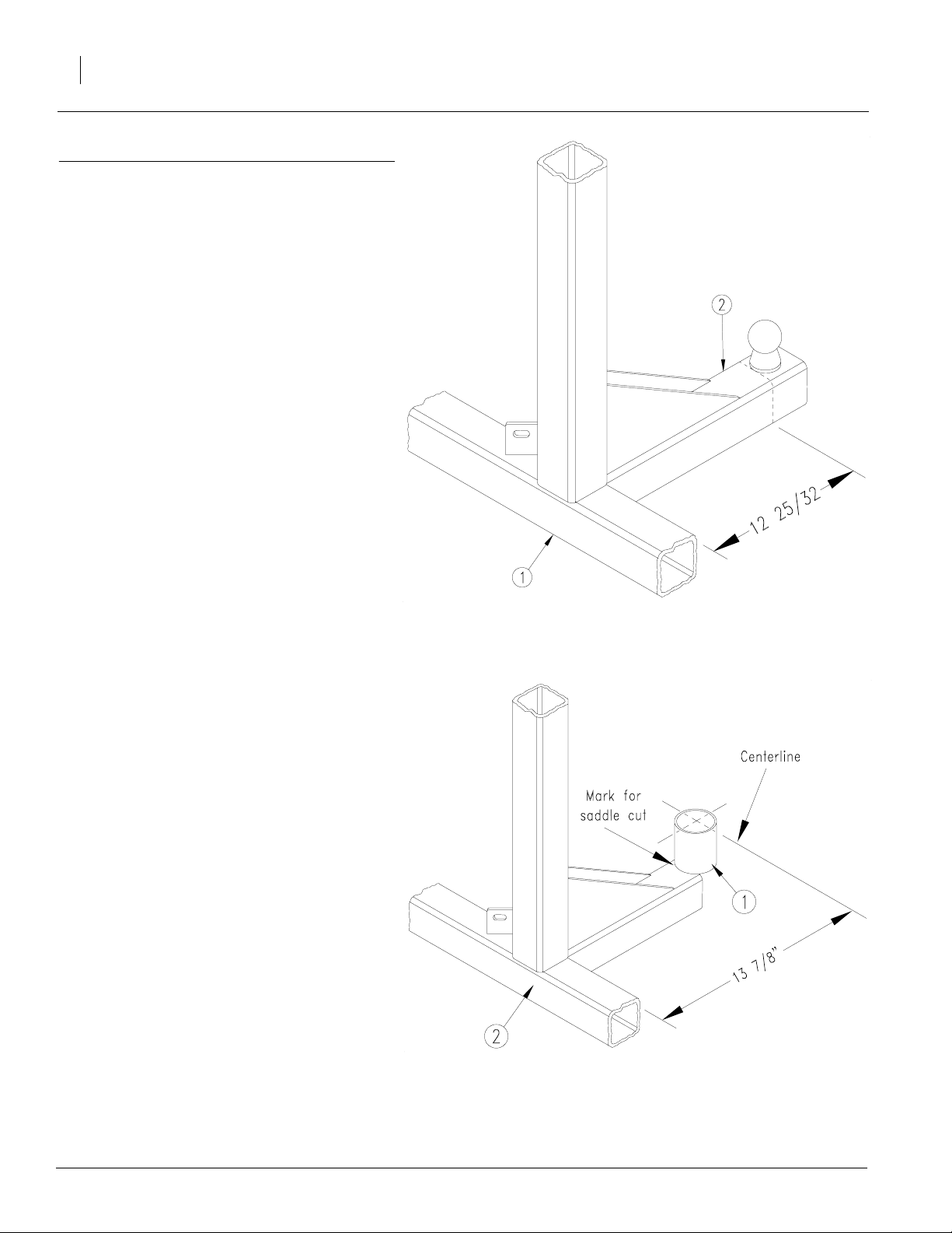
Refer to Figure 1
4. Measure 12 25/32" from the front surface of
square tube (1) towards the outer end of
square tube (2).
Note:Cut tube alittlelongerto allowforgrindingto
make the end square.
5. Using a torch, carefully cut tube (2).
6. Grind the surfacesofthesquaretubesmooth.
Great Plains Mfg., Inc.
Refer to Figure 2
7. Placethespindlehubassembly(1) on the top
surfaceof the squaretube (2). Measurefrom
the center point of the spindle hub assembly
to the front surface of the square tub 13 7/8".
8. Use the spindle hub assembly as a template
to mark whereto cutasaddle into thesquare
tube.
9. Use a torch to make a saddle cut in the
square tube and smooth the surfaces with a
grinder.
Note: Be carefulwhen using the spindlehub as a
template,there are bearing cupsontheinside.Do
not use as a gig for torching the saddle cut.
20224
Figure 1
Remove Old Pivot Ball
20225
Figure 2
Marking for the Saddle Cut
104-010M 4/9/2004
Page 3
Great Plains Mfg., Inc.
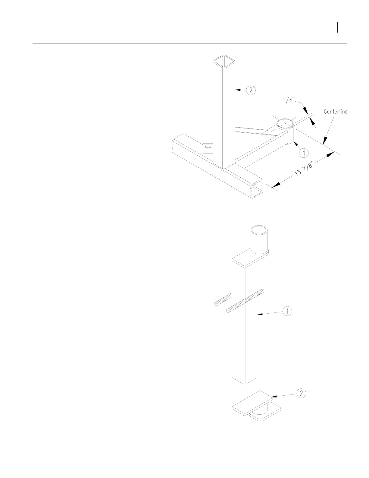
Refer to Figure 3
10. Center the spindle hub assembly (1) on the
square tube wherethe saddlecut was made.
Positionthe hub so the top edge is raised 1/4"
above the topsurface of thetube. Make sure
the centerline of the hub is 13 7/8" from the
front surface of the square tube.
11. Clamp the spindle hub assembly (1) in place
and make sure it is plum with the upright
square tube (2). Clamp only to theoutside of
the hub.
Note: Make sure the measurementsare accurate
andthehub is plum with the tube. Securely clamp
the hub in place before welding.
12. Coverthe openings of the spindle hub assembly (1) so not to allow any welding sparks or
beadstoget inside. Thisisnecessaryinorder
to protect the bearing cups on the inside of
the hub.
13. Weld the spindle hub assembly (1) in place
using a weld with high tensile strength.
20226
Installation Instructions
Figure 3
Spindle Hub Assembly
3
Refer to Figure 4
14. If you are reusing the pivot post (1) it will be
necessary to removethe old pivot bracket(2).
15. Afterremovingoldbracket(2) smooth the surfaces of the pivot post(1).
4/9/2004
20227
Figure 4
Pivot Post
104-010M
Page 4

Post Conversion Update
4
Refer to Figure 5
16. Attachthe U-joint post side plates (1) toopposite sides of the old pivot post (2). Place the
plates with the their holes down and extending out in thesame direction as theround pivot tube (3) on top.
17. Measure 31 7/16" from the top edge of the
round pivot tube (3)to the centerlineof the Ujoint post side plates (1). Measure back 1/8"
from the frontedge of the oldpivotpost (2) to
the centerline of the U-joint post side plates
(1).
18. Clamp U-joint post side plates (1) to the old
pivot post (2) and recheck your measurements before welding.
19. Insert the 6 3/4" long post pivot bolt (4)
through the holes in the U-joint post side
plates (1). Thebolt should movefreely, if not,
check your measurements.
Great Plains Mfg., Inc.
20. Hold the 1/4" squarekey (5) againstthe plate
(1) and head of bolt (4). Tack weldit tothe
plate.This willkeepthe boltfromturningwhile
tightening the nut later.
21. Remove the bolt (4).
22. Weld U-joint post side plates (1) and 1/4"
square key in place using a weld with high
tensile strength.
Refer to Figure 6
23. Afterallowingthespindlehubassembly(1) to
cool, remove anydirt or foreign material
which might have gotten inside.
24. Packthe topbearing cone (2) with wheel
bearing greaseand insert it in the top of the
spindle hub assembly (1).
25. Install the grease seal (3) and insert the lefthand U-joint spindle (4).
26. Packthe bottom bearing cone (5) with wheel
bearing greaseand insert it in the bottom of
the spindle hub assembly (1).
20221
Figure 5
Old Pivot Post
27. Install the 7/8" flat washer (6) and thread on
the 7/8" slotted hex nut (7). Snug the nut(7)
while moving the U-jointspindle (4) back and
forth. Afterthe snuggingthe nut back it off
about 1/2 a turn. Line one of the slots in the
nut (7) with the hole in the U-joint spindle (4)
and insert the cotter pin (8).
28. Install the hub cap (9) on the spindle hub assembly (1).
104-010M 4/9/2004
20222
Figure 6
Spindle Hub Assembly
Page 5

Great Plains Mfg., Inc.
Refer to Figure 7
29. Install the top round tube of the pivot post (1)
into the pivot post cap on themain drillframe.
30. Rotate the U-joint spindle (2) so the hole for
the cylinder clevis (6) is facing towards the
closing cylinder lug (7).
31. Align the holes in the U-joint post side plates
on the pivot post (1) with the U-joint spindle
(2).
32. Insert the 6 3/4" long pivot bolt (3) and position it so the head rests against the 1/4"
squarekeyso the boltwillnotturnwhilebeing
tightened. Secure bolt with the 1 1/4" lock
washer(4)and 1 1/4" hex nut(5).Tightennut.
Installation Instructions
5
Refer to Figure 8
33. Place the closing cylinder lug (1) on top of
square tube (2).
34. From the centerline of the hole in the closing
cylinder lug (1) measure 16 7/8"to the centerline of the square tube(3). Measure fromthe
centerline of the lug (1) 1 3/8" to the edge of
the square tube (2).
35. Clamp lug (1) and weld in place using a high
tensile strength weld.
36. Reinstall the hydraulic cylinder.
37. Reattach the left-hand drill box tothe pivot
post.
38. Repeat the procedureto install thepivotpost
conversion kit on the right-hand side of the
drill substituting right forleft.
20223
Figure 7
Installing Pivot Post
20229
4/9/2004
Figure 8
Closing Cylinder Lug
104-010M
Page 6

Great Plains Mfg., Inc.
104-008A RH FULL PRESS POST AND CONV KIT
Your kit includes:
Qty. Part No. Part Description
1 104-011K RH FULL PRESS CONV KIT
1 128-002H HC POST WELDED ASSEMBLY RH
Installation Instructions
6
104-009A LH FULL PRESS POST AND CONV KIT
Your kit includes:
Qty. Part No. Part Description
1 104-012K LH FULL PRESS POST KIT
1 128-001H HC POST WELDED ASSEMBLY LH
104-010M4/9/2004
Page 7

Great Plains Mfg., Inc.
104-011K RH FULL PRESS POST CONV KIT
Your kit includes:
Qty. Part No. Part Description
1 104-010M MANUAL FULL PRESS POST CON
1 109-031D JACK SHAFT - KEY
1 125-001H U JOINT SPINDLE RH
1 125-005S SPINDLE HUB ASSEMBLY
1 125-066D CLOSING CYLINDER LUG
2 128-053D U-JOINT POST SIDE PLATE
1 156-022H POST PIVOT BOLT
1 800-001C GREASE ZERK STRAIGHT 1/4-28
1 803-029C NUT HEX SLOTTED 7/8-14 PLT
1 803-034C NUT HEX 1 1/4-7 PLT
1 804-026C WASHER FLAT 7/8 SAE PLT
1 804-030C WASHER LOCK 1 1/4 SPRING PLT
1 805-016C PIN COTTER 3/16 X 1 1/4 PLT
1 816-012C SEAL 3.375 X 2.0 X.438 CR2
1 822-014C BEARING CONE 25590
1 822-016C BEARING CONE 25877
1 890-032C HUB CAP
Installation Instructions
7
104-012K LH FULL PRESS CONVERSION KIT
Your kit includes:
Qty. Part No. Part Description
1 104-010M MANUAL FULL PRESS POST CON
1 109-031D JACK SHAFT - KEY
1 125-002H U JOINT SPINDLE LH
1 125-005S SPINDLE HUB ASSEMBLY
1 125-066D CLOSING CYLINDER LUG
2 128-053D U-JOINT POST SIDE PLATE
1 156-022H POST PIVOT BOLT
1 800-001C GREASE ZERK STRAIGHT 1/4-28
1 803-029C NUT HEX SLOTTED 7/8-14 PLT
1 803-034C NUT HEX 1 1/4-7 PLT
1 804-026C WASHER FLAT 7/8 SAE PLT
1 804-030C WASHER LOCK 1 1/4 SPRING PLT
1 805-016C PIN COTTER 3/16 X 1 1/4 PLT
1 816-012C SEAL 3.375 X 2.0 X.438 CR2
1 822-014C BEARING CONE 25590
1 822-016C BEARING CONE 25877
1 890-032C HUB CAP
4/9/2004
104-010M
 Loading...