

Page 1
Great Plains Manufacturing, Inc. 1
Flex Harrow Light Kit
Installation Instructions
General Information
These Instructions explain how to install the flex harrow
light update kit. The lights will be shipped mounted to
brackets.
MetaData: of <Safety Topics>Introduction
Tools Required
• Basic Hand Tools
• Drill & Drill Bits
• Welder (optional)
Models Covered
Flex Harrow 6000
Note: Refer to Parts manual (564-070P) for machine parts
breakdown. The brackets may be welded on instead
of drilling holes and bolted on. Use drill placement
drawings if welding on. Align holes in brackets to dimensions in drawings. Remove old wiring harness
and light brackets.
564-091A FLEX HARROW LIGHT KIT
Part #
564-088H LIGHT BRACKET 2
564-090H LIGHT BRACKET 2
801-081C SCREW HEX SELF TAP 1/4-20X3/4 8
564-092M
FLEX HARROW LIGHT UPDATE
802-005C HHCS 1/4-20X1 GR5 12
802-091C HHCS 1/2-13X1 1/2 GR5 4
803-007C NUT-LOCK 1/4-20 PLT 12
803-020C NUT HEX 1/2-13 PLT 4
804-015C WASHER LOCK SPRING 1/2 PLT 4
838-603C DECAL REFLECTOR ORANGE 2X9 2
838-614C DECAL REFLECTOR RED 2X9 2
838-615C DECAL REFLECTOR AMBER 2X9 4
890-901C SAFETY LIGHT KIT 1
Description Qty.
KIT
1
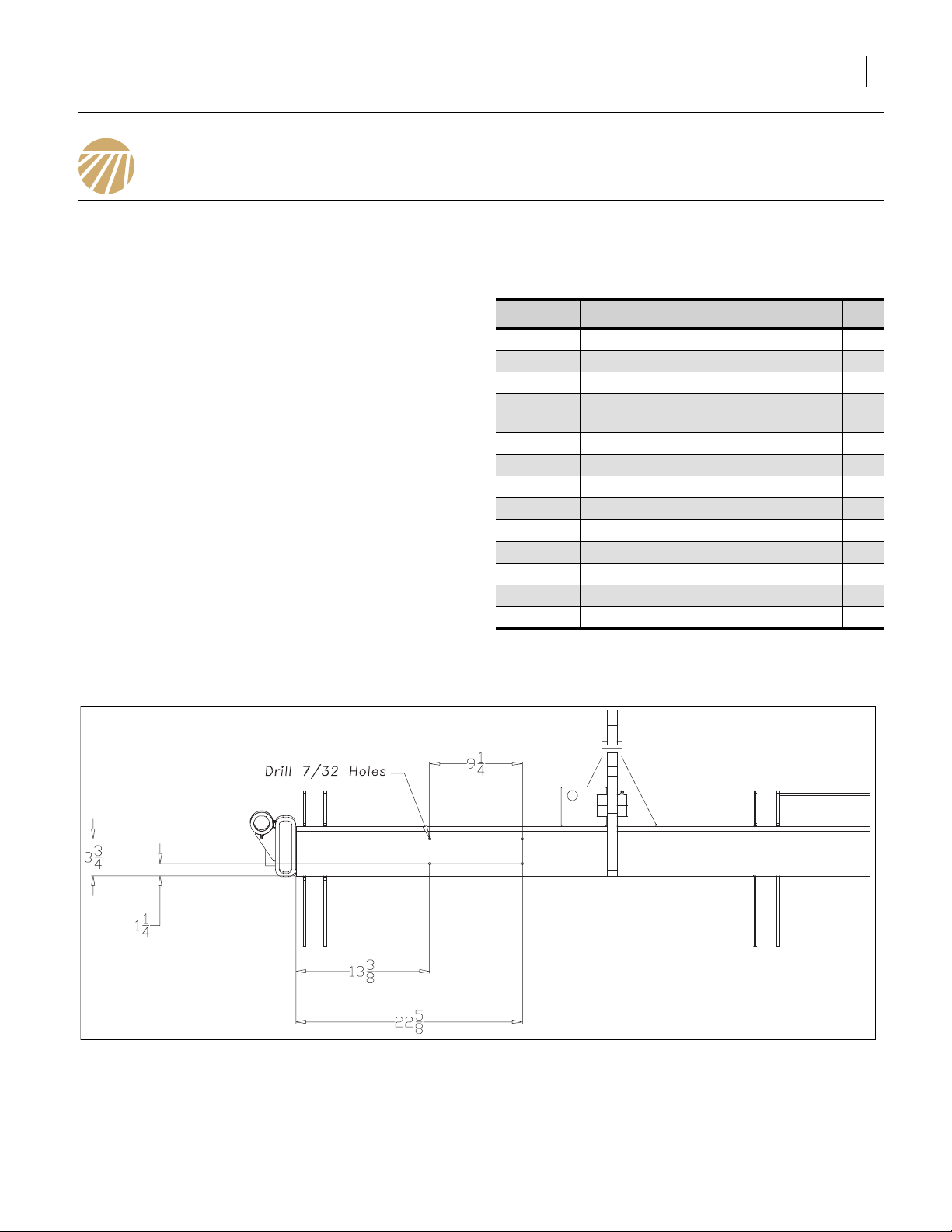
Bottom Hole Placement
Refer to Figure 1
1. Drill four 7/32 holes in location shown on both sides.
Null4:
Bottom Hole Placement
Null4:
Null4:
Figure 1
42305
12/15/2011 564-092M
Page 2
2 Light Kit Great Plains Manufacturing, Inc.
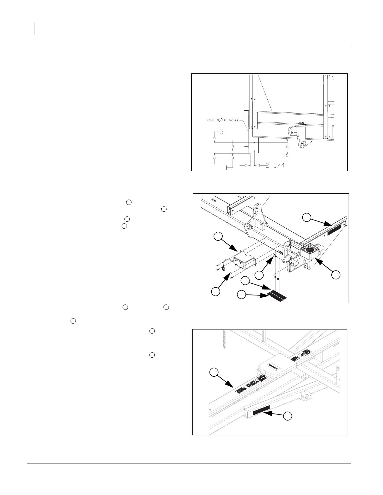
Side Hole Placement
Refer to Figure 2
2. Drill two 9/16 holes in location shown on both sides.
Light Bracket Mounting
Refer to Figure 3
3. Fasten light bracket assembly to the pre-drilled
holes with the 1/4 x 3/4 self tapping screws .
4. Fasted light bracket assembly in position shown
with the 1/2 x 1 1/2 hex bolts , 1/2 lock washers
and 1/2 nuts.
5. Tighten all bolts.
6. Route wiring harness from front of hitch along
hydraulic hoses and across to light brackets. Route
wires through bent tubing on outer light brackets and
plug ends into lights as marked on harness.
7. Fasten wiring harness with plastic ties or hose clips.
Be sure wire is fastened securely so it doesn’t drag
or get pinched when folding machine.
8. Clean surface and attach red and orange
decals on bottom of tube in line with light bracket
assembly as shown on both sides.
1
9. Clean surface and attach amber decal in position
shown on both sides of center frame bracket.
Refer to Figure 4
10. Clean surface and attach amber decal in position
shown on both sides of hitch angle tube.
1
2
3
4
5 6
7
7
FigureSpacer:
FigureSpacer:
Figure 2
42306
Side Hole Placement
7
1
4
3
5
2
6
Figure 3
Light Bracket Mounting
42307
7
7
FigureSpacer:
Figure 4
Amber Decals Hitch Location
564-092M 12/15/2011
42406
 Loading...