

Table of Contents Index
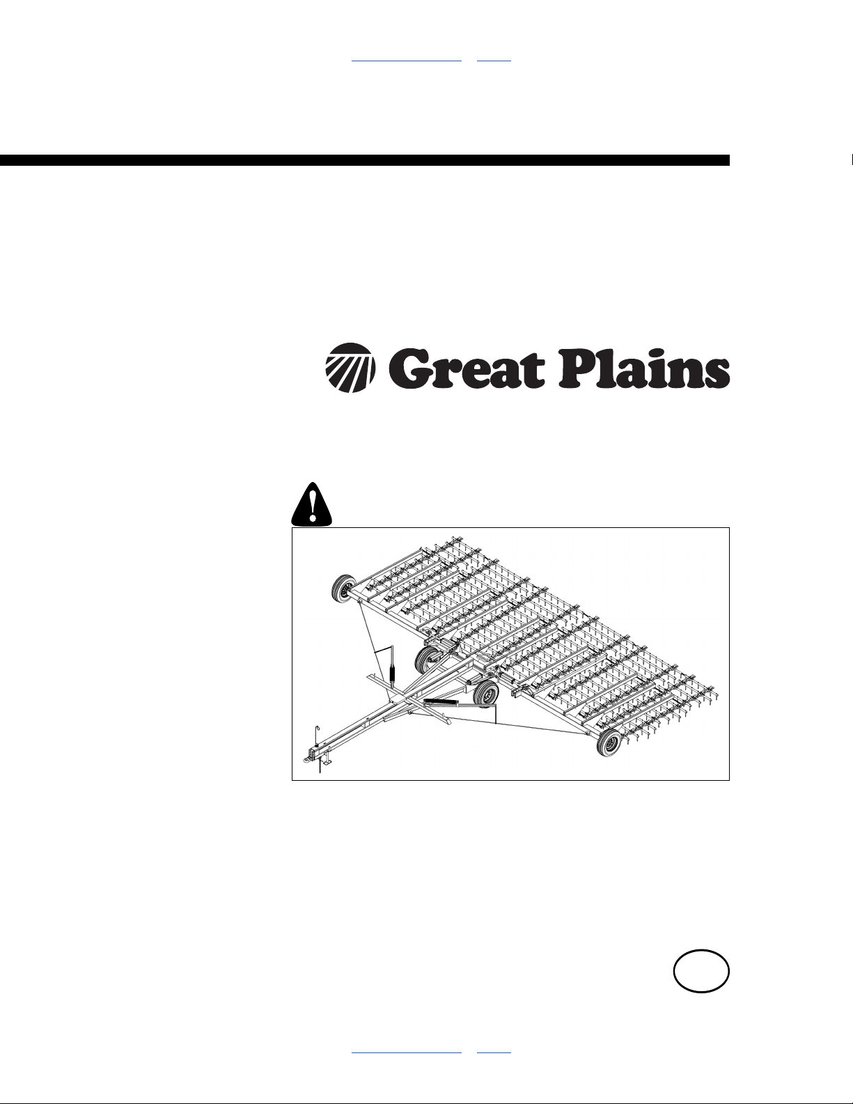
Operator Manual
6000 Series Harrow
FH6424HD, FH6330HD, FH6336HD, FH6642HD,
FH6845HD, FH6848HD & FH6851HD
Manufacturing, Inc.
www.greatplainsmfg.com
Read the operator’s manual entirely. When you see this symbol, the
subsequent instructions and warnings are serious - follow without
exception. Your life and the lives of others depend on it!
31686
Illustrations may show optional equipment not supplied with standard unit, or may show
wider or narrower models where the topic function is identical.
ORIGINAL INSTRUCTIONS
© Copyright 2014 Printed 2014-04-28 564-070M
Table of Contents Index
EN

Table of Contents Index
Table of Contents Index

Great Plains Manufacturing, Inc. iii
Table of Contents
A.Important Safety Information...................................1
Safety Decals ................................................................. 5
Introduction ................................................................10
Description of Unit ........................................................10
Models Covered ........................................................... 10
Intended Usage ........................................................10
Document Family......................................................10
Using This Manual........................................................10
Definitions................................................................. 10
Owner Assistance ........................................................11
Preparation and Setup ...............................................12
Initial Setup...................................................................12
Post-Delivery/Seasonal Setup......................................12
Pre-Application Setup...................................................12
Hitching Harrow to Tractor ...........................................13
Electrical Hookup......................................................14
Hydraulic Hose Hookup............................................ 14
Operating Instructions...............................................15
Pre-Start Checklist .......................................................15
Unfold Harrow ..............................................................16
Fold ..............................................................................18
Transport ......................................................................19
Harrow Transport Weights........................................19
Transport Steps........................................................19
Field Operation.............................................................20
Field Set-Up Checklists ................................................20
Short-Term Parking ......................................................21
Long-Term Storage ...................................................... 21
Adjustments................................................................22
Wing Fold Height Adjustment.......................................22
FH6424HD to FH6642HD Wing Fold Height............22
FH6845HD to FH6851HD Wing Fold Height............ 23
FH6636 to FH6851HD Wing Adjustment ................. 24
Troubleshooting......................................................... 25
Maintenance and Lubrication ................................... 26
Maintenance ................................................................ 26
Hydraulic Maintenance ................................................ 27
Bleeding Hydraulics ................................................. 28
Lubrication and Scheduled Maintenance..................... 29
Options ....................................................................... 31
Appendix A - Reference Information........................ 32
Specifications and Capacities ...................................... 32
Model FH6400HD Specifications and Capacities .... 32
Model FH6600HD Specifications and Capacities .... 32
Model FH6800HD Specifications and Capacities .... 33
Tire Inflation & Warranty .............................................. 33
Torque Values Chart.................................................... 34
Appendix B - Initial Setup ......................................... 35
Post-Delivery Checklist ................................................ 35
Hitch Configuration ...................................................... 35
Hitch Height or Hitch Inversion................................. 35
Clevis Hitch .............................................................. 36
Category III Hitch ..................................................... 36
Tooth Angle.................................................................. 37
Spot Implement ........................................................ 37
Disconnect/Move Leading Chains............................ 37
Disconnect Trailing Chains ...................................... 38
Reconnect Leading Chains ...................................... 38
Reconnect Trailing Chains ....................................... 38
Install Row Extensions................................................. 39
Install Wing Extensions................................................ 40
Index............................................................................ 43
© Copyright 2006, 2007, 2008, 2009, 2010, 2011, 2012, 2013, 2014 All rights Reserved
Great Plains Manufacturing, Inc. provides this publication “as is” without warranty of any kind, either expressed or implied. While every precaution has been
taken in the preparation of this manual, Great Plains Manufacturing, Inc. assumes no responsibility for errors or omissions. Neither is any liability assumed for
damages resulting from the use of the information contained herein. Great Plains Manufacturing, Inc. reserves the right to revise and improve its products as
it sees fit. This publication describes the state of this product at the time of its publication, and may not reflect the product in the future.
04/28/2014 564-070M
Trademarks of Great Plains Manufacturing, Inc. include: Singulator Plus, Swath Command, Terra-Tine.
Registered Trademarks of Great Plains Manufacturing, Inc. include:
Air-Pro, Clear-Shot, Discovator, Great Plains, Land Pride, MeterCone, Nutri-Pro, Seed-Lok, Solid Stand,
Terra-Guard, Turbo-Chisel, Turbo-Chopper, Turbo Max, Turbo-Till, Ultra-Till, Verti-Till, Whirlfilter, Yield-Pro.
Brand and Product Names that appear and are owned by others are trademarks of their respective owners.
Printed in the United States of America

iv FH6000HD Great Plains Manufacturing, Inc.
564-070M 04/28/2014
Great Plains Manufacturing, Inc. 1
A.Important Safety Information
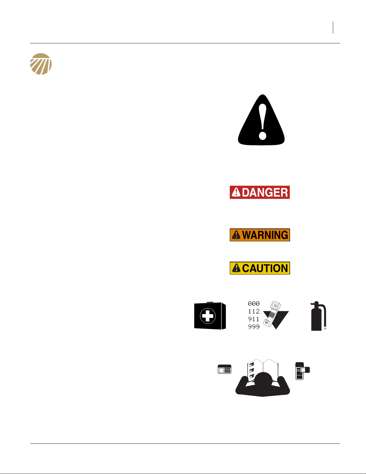
Look for Safety Symbol
The SAFETY ALERT SYMBOL indicates there is a
potential hazard to personal safety involved and extra
safety precaution must be taken. When you see this
symbol, be alert and carefully read the message that follows it. In addition to design and configuration of equipment, hazard control and accident prevention are
dependent upon the awareness, concern, prudence and
proper training of personnel involved in the operation,
transport, maintenance and storage of equipment.
Be Aware of Signal Words
Signal words designate a degree or level of hazard seriousness.
DANGER indicates an imminently hazardous situation
which, if not avoided, will result in death or serious injury.
This signal word is limited to the most extreme situations,
typically for machine components that, for functional purposes, cannot be guarded.
WARNING indicates a potentially hazardous situation
which, if not avoided, could result in death or serious
injury, and includes hazards that are exposed when
guards are removed. It may also be used to alert against
unsafe practices.
CAUTION indicates a potentially hazardous situation
which, if not avoided, may result in minor or moderate
injury. It may also be used to alert against unsafe practices.
Prepare for Emergencies
▲ Be prepared if a fire starts.
▲ Keep a first aid kit and fire extinguisher handy.
▲ Keep emergency numbers for doctor, ambulance, hospital
and fire department near phone. Know the reporting
requirement for spills or releases of the chemicals you are
using. Have contact numbers available.
Be Familiar with Safety Decals
▲ Read and understand “Safety Decals” on page 5, thor-
oughly.
▲ Read all instructions noted on the decals.
▲ Keep decals clean. Replace damaged, faded and illegible
decals.
04/28/2014 564-070M

2 FH6000HD Great Plains Manufacturing, Inc.
Use Safety Chains
▲ Use safety chains to help control drawn machinery should it
separate from tractor draw-bar or trailing nurse tank hitch.
▲ Use chain with a strength rating equal to or greater than
the gross weight of towed machinery.
▲ Attach implement chain to tractor draw-bar support or
specified anchor location. Allow only enough slack in chain
for turns.
▲ Replace chain if any links or end fittings are broken,
stretched or damaged.
▲ Do not use safety chain for towing.
Avoid High Pressure Fluids
Escaping fluid under pressure can penetrate the skin,
causing serious injury. This flex harrow requires a PowerBeyond port, which is always under pressure when the
tractor is running.
▲ Avoid the hazard by relieving pressure at other remotes, and
shutting down tractor before connecting, disconnecting or
inspecting hydraulic lines.
▲ Use a piece of paper or cardboard, NOT BODY PARTS, to
check for suspected leaks.
▲ Wear protective gloves and safety glasses or goggles when
working with hydraulic systems.
▲ If an accident occurs, seek immediate medical assistance
from a physician familiar with this type of injury.
Keep Riders Off Machinery
Riders obstruct the operator’s view. Riders could be
struck by foreign objects or thrown from the machine.
▲ Never allow children to operate equipment.
▲ Keep all bystanders away from machine during operation.
Use Safety Lights and Devices
Slow-moving tractors and towed implements can create
a hazard when driven on public roads. They are difficult
to see, especially at night.
▲ Use flashing warning lights and turn signals whenever driv-
ing on public roads.
▲ Use lights and devices provided with implement.
564-070M 04/28/2014

Great Plains Manufacturing, Inc. A.Important Safety Information 3
Transport Machinery Safely
Maximum transport speed for implement is 20 mph (32
kph), 13 mph (22 kph) in turns. Some rough terrains
require a slower speed. Sudden braking can cause a
towed load to swerve and upset.
▲ Do not tow an implement or nurse tank that weighs more
than 1.5 times the weight of towing vehicle.
▲ Carry reflectors or flags to mark flex harrow in case of
breakdown on the road.
▲ Keep clear of overhead power lines and other obstructions
when transporting. Refer to transport dimensions under
“Specifications and Capacities” on page 32.
▲ Do not exceed 20 mph. Never travel at a speed which does
not allow adequate control of steering and stopping. Reduce
speed if towed load is not equipped with brakes.
▲ Reduce speed on rough roads.
▲ Comply with national, regional and local laws.
▲ Do not fold or unfold the flex harrow while the tractor is
moving.
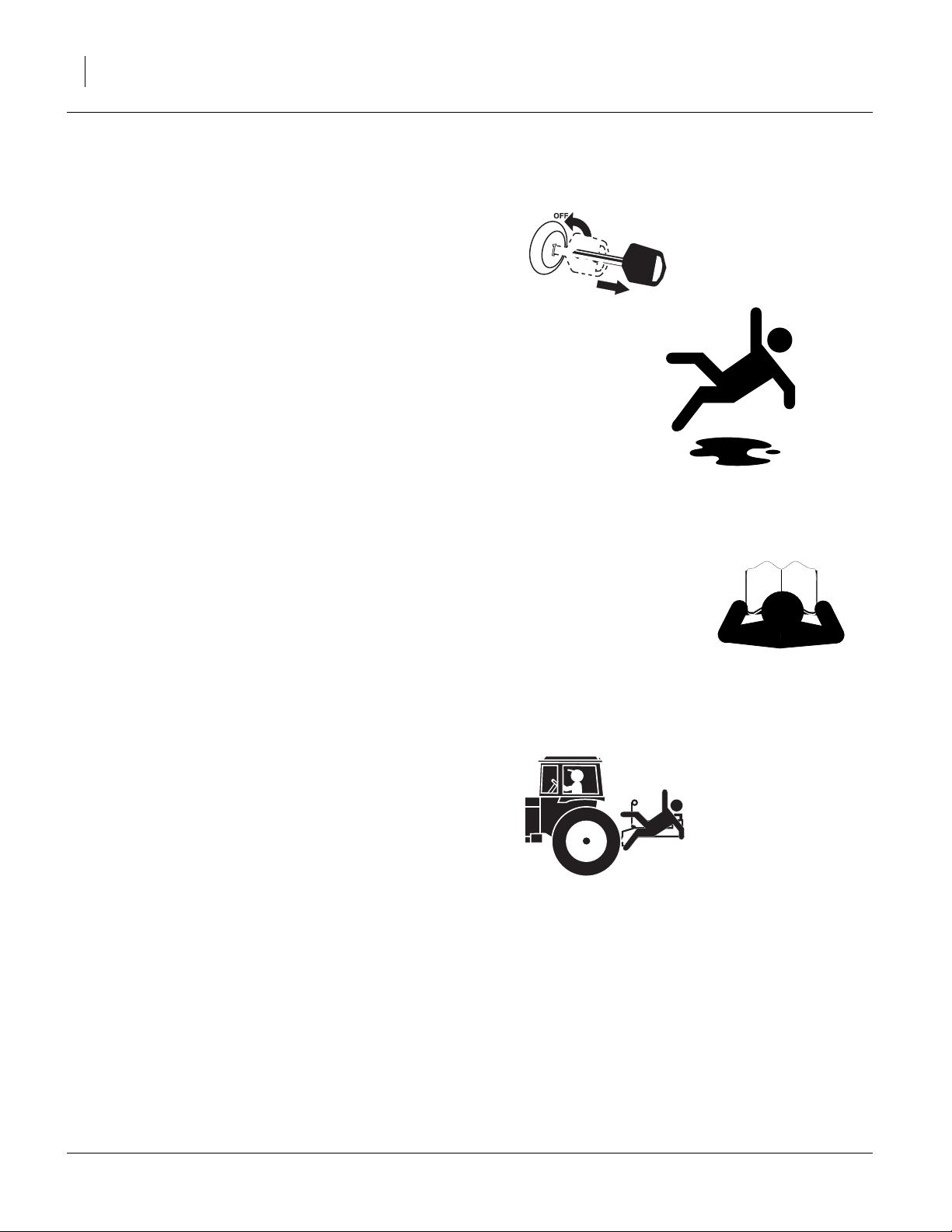
Shutdown and Storage
▲ Lower flex harrow, put tractor in park, turn off engine, and
remove the key.
▲ Secure flex harrow using parking jack provided.
▲ Detach and store flex harrow in an area where children nor-
mally do not play.
Tire Safety
Tire changing can be dangerous. Employ trained personnel using correct tools and equipment.
▲ When inflating tires, use a clip-on chuck and extension hose
long enough for you to stand to one side–not in front of or
over tire assembly. Use a safety cage if available.
▲ When removing and installing wheels, use wheel-handling
equipment adequate for weight involved.
04/28/2014 564-070M
4 FH6000HD Great Plains Manufacturing, Inc.
Practice Safe Maintenance
▲ Understand procedure before doing work. Use proper
tools and equipment. Refer to this manual for additional
information.
▲ Work in a clean, dry area.
▲ Lower implement, put tractor in park, turn off engine, and
remove key before performing maintenance.
▲ Make sure all moving parts have stopped and all system
pressure is relieved.
▲ Disconnect battery ground cable (-) before servicing or
adjusting electrical systems or before welding on flex harrow.
▲ Inspect all parts. Make sure parts are in good condition
and installed properly.
▲ Remove buildup of grease, oil or debris.
▲ Remove all tools and unused parts from implement before
operation.
Safety At All Times
Thoroughly read and understand the instructions in this
manual before operation. Read all instructions noted on
the safety decals.
▲ Be familiar with all flex harrow functions.
▲ Operate machinery from the driver’s seat only.
▲ Do not leave flex harrow unattended with tractor engine
running.
▲ Do not stand between tractor and implement, or implement
and nurse tank, during hitching.
▲ Keep hands, feet and clothing away from power-driven
parts.
▲ Wear snug-fitting clothing to avoid entanglement with mov-
ing parts.
▲ Watch out for wires, trees, etc., when folding and raising
flex harrow. Make sure all persons are clear of working
area.
564-070M 04/28/2014
Great Plains Manufacturing, Inc. A.Important Safety Information 5
Safety Decals
Safety Reflectors and Decals
Your implement comes equipped with all lights, safety
reflectors and decals in place. They were designed to
help you safely operate your implement.
▲ Read and follow decal directions.
▲ Keep lights in operating condition.
▲ Keep all safety decals clean and legible.
▲ Replace all damaged or missing decals. Order new decals
from your Great Plains dealer. Refer to this section for
proper decal placement.
▲ When ordering new parts or components, also request cor-
responding safety decals.
To install new decals:
1. Clean the area on which the decal is to be placed.
2. Peel backing from decal. Press firmly on surface,
being careful not to cause air bubbles under decal.
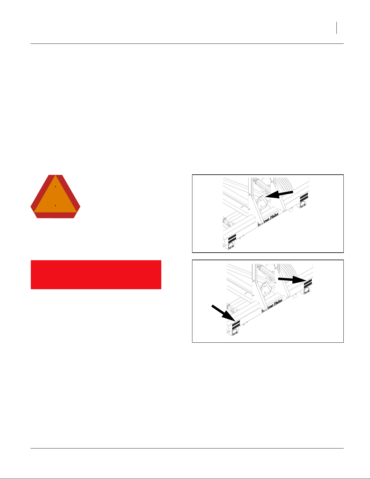
42317
818-055C
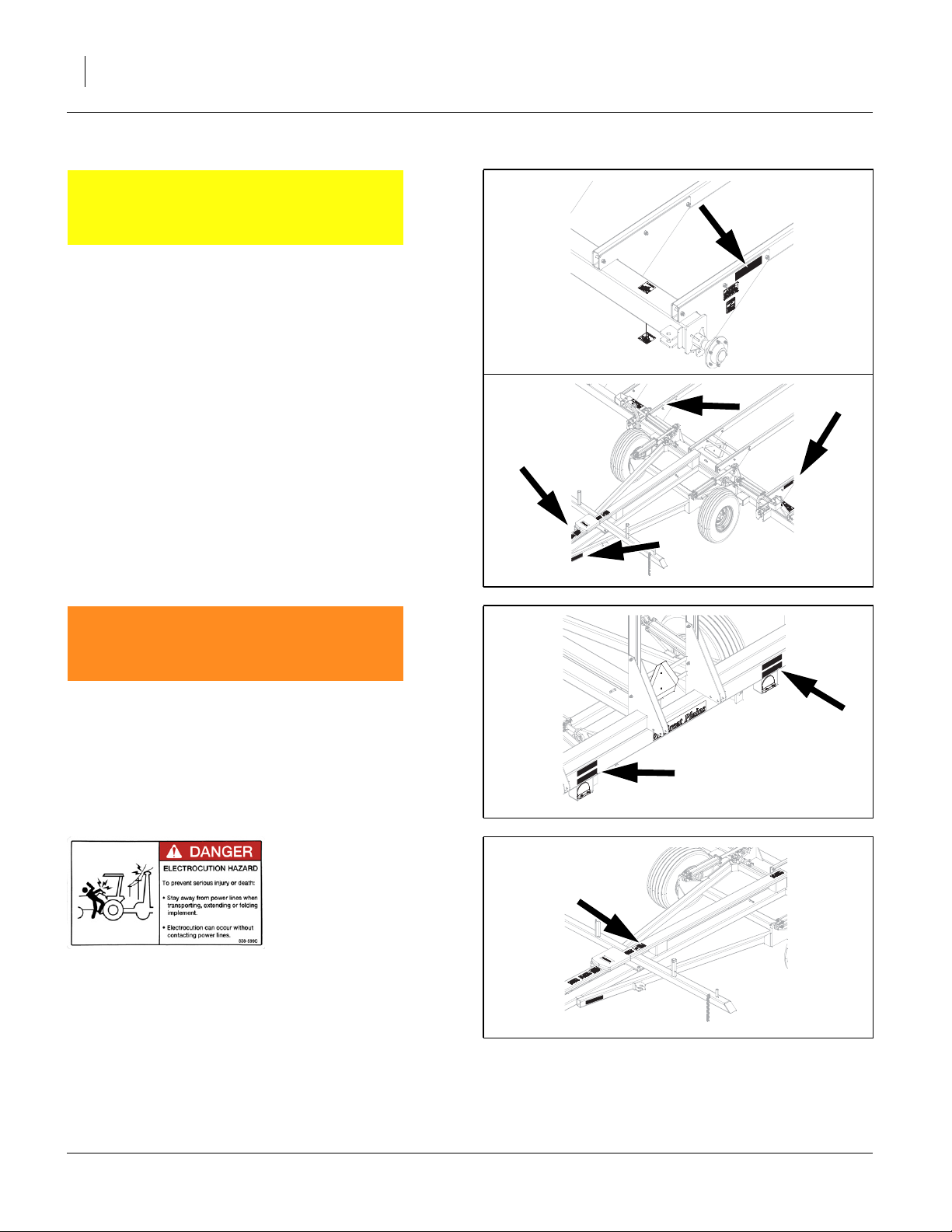
Slow Moving Vehicle Reflector
On cross-bars at center of center wing;
1 total
838-614C
Red Reflectors
On rear of center wing (top) when folded up (both sides);
2 total
42317
04/28/2014 564-070M
6 FH6000HD Great Plains Manufacturing, Inc.
838-615C
Amber Reflectors
On outside face of wing end arm mounts, on outside of
outer arm of center and on outside of tongue, front, angle
tube (both sides);
6 total
42318
838-603C
Daytime (Orange) Reflectors
On rear of center wing (bottom) when folded up (both
sides);
2 total
838-599C Danger: Electrocution
On top face of tongue rear of manual pak (rear);
1 total
42324
42317
42320
564-070M 04/28/2014
Great Plains Manufacturing, Inc. A.Important Safety Information 7
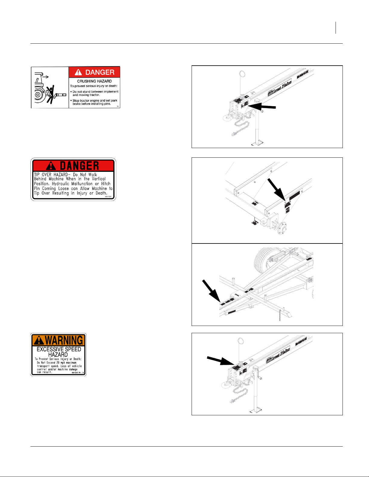
838-600C Danger: Hitch Crush
On side face of tongue near hitch;
1 total
42319
848-705C Danger: Tip Over Hazard
On outside of wing end arm mount (both sides), on top
face of tongue front of manual pak (front);
3 total
818-337C Warning: Speed
On top face of tongue near hitch (rear);
1 total
42318
42320
42319
04/28/2014 564-070M
8 FH6000HD Great Plains Manufacturing, Inc.
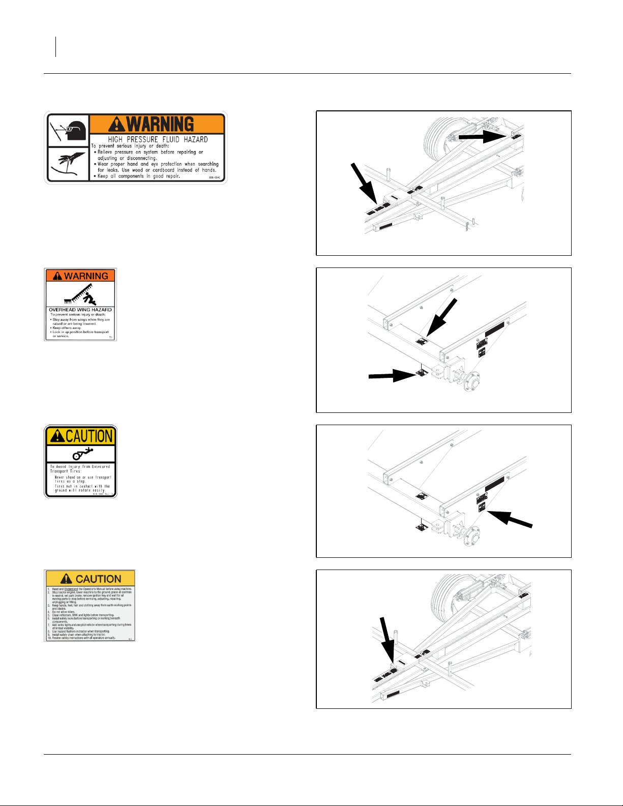
838-094C Warning: High Pressure Fluid Hazard
One on top face of tongue in front of manual pak (middle), one on rear of hitch;
2 total
42320
838-602C Warning: Overhead Wing
On front (when unfolded) face of wing frame near wing
wheel (top and bottom of tube) (both sides);
4 total
818-398C Caution: Tires Not a Step
On outside face of wing end arm mount (both sides);
2 total
42318
42318
838-598C Caution: Read Operator’s Manual
On top face of tongue in front of manual pak (rear);
1 total
564-070M 04/28/2014
42320

Great Plains Manufacturing, Inc. A.Important Safety Information 9
NOTICE
TIP OVER HAZARD –
Do Not Attempt to Fold or Unfold
Machine Unless Securely Attached
to the Towing Tractor.
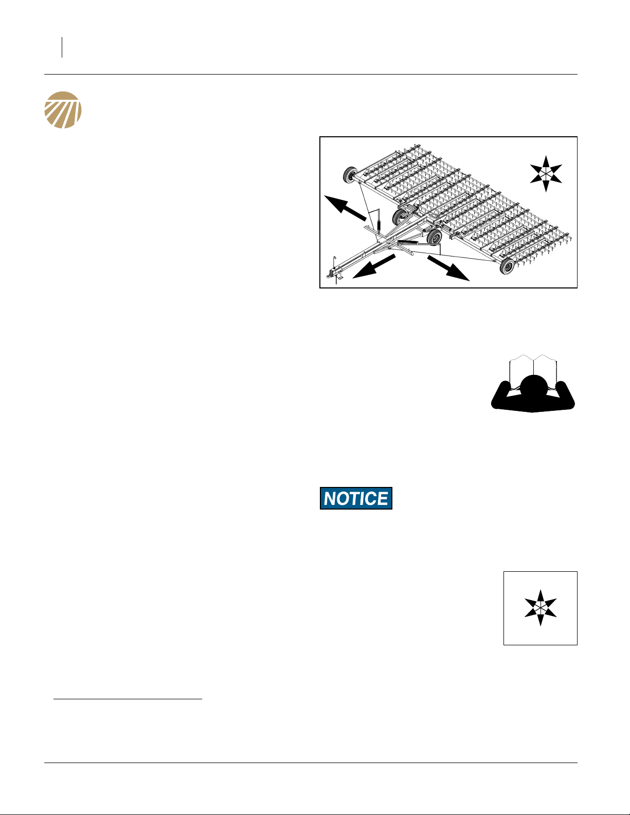
848-706C Notice: Tip Over Hazard
On top face of tongue near hitch (front);
1 total
848-706C
42319
04/28/2014 564-070M
10 FH6000HD Great Plains Manufacturing, Inc.
Introduction
Great Plains welcomes you to its growing family of new
product owners. The Flex Harrow (FH6000HD1 family)
has been designed with care and built by skilled workers
using quality materials. Proper setup, maintenance, and
safe operating practices will help you get years of satisfactory use from the machine.
Description of Unit
The FH6400HD, FH6600HD & FH6800HD Flex Harrow
is a heavy-duty flexible-link spike harrow. It is a pull-type
implement intended for towing directly behind a tractor,
or behind another implement. The outer sections fold up
and forward for narrow (12 ft 8 in) transport.
Models Covered
FH6424HD FH6000, 12-Bar, 24-Foot, Heavy-Duty
FH6630HD FH6000, 12-Bar, 30-Foot, Heavy-Duty
FH6636HD FH6000, 12-Bar, 36-Foot, Heavy-Duty
FH6642HD FH6000, 12-Bar, 42-Foot, Heavy-Duty
FH6845HD FH6000, 12-Bar, 45-Foot, Heavy-Duty
FH6848HD FH6000, 12-Bar, 48-Foot, Heavy-Duty
FH6851HD FH6000, 12-Bar, 41-Foot, Heavy-Duty
U
R
F
D
R
L
Figure 1
Flex Harrow
Using This Manual
This manual will familiarize you with
safety, assembly, operation, adjustments, troubleshooting, and maintenance. Read this manual and follow
the recommendations to help
ensure safe and efficient operation.
The information in this manual is current at printing.
Some parts may change to assure top performance.
31686
B
L
Intended Usage
Use the Flex Harrow to level soil, firm seedbeds, break
up and spread residue. Do not modify Great Plains-provisioned components, or install user-provisioned components, except as authorized or recommended by Great
Plains.
Document Family
564-070M MANUAL 6424-6845HD FLEX H
(this document)
584-070Q PART MAN 6424-6845HD FLEX H
584-070Q PRE-DELIV MAN 6424-6845HD FH
564-000M MANUAL, MARTENS HARROWS FF,
HD
1. The Great Plains FH6000HD product line is based on Model HD harrows previously offered by Martens Manufacturing, Fairview OK.
The present manual (564-070M) is intended for use with FH6000HD family harrows made by Great Plains. Owners of older (2010 and
earlier) Martens HD harrows may rely on their existing Martens manual. The final edition of that manual is available on the Great
Plains web site as Great Plains part number 564-000M. Great Plains provides continuing support for Martens HD harrows.
Definitions
The following terms are used throughout this manual.
A crucial point of information related to the preceding topic.
Read and follow the directions to remain safe, avoid serious
damage to equipment and ensure desired field results.
Note: Useful information related to the preceding topic.
Right-hand and left-hand as used in
this manual are determined by facing
the direction the machine will travel
while in use unless otherwise stated.
An orientation rose in some line art
illustrations shows the directions of:
Up, Back, Left, Down, Front, Right.
“(Option)” refers to components not part of the standard
product, and not “optional” steps.
R
F
U
B
L
D
564-070M 04/28/2014
Great Plains Manufacturing, Inc. Introduction 11
Owner Assistance
If you need customer service or repair parts, contact a
Great Plains dealer. They have trained personnel, repair
parts and equipment specially designed for Great Plains
products.
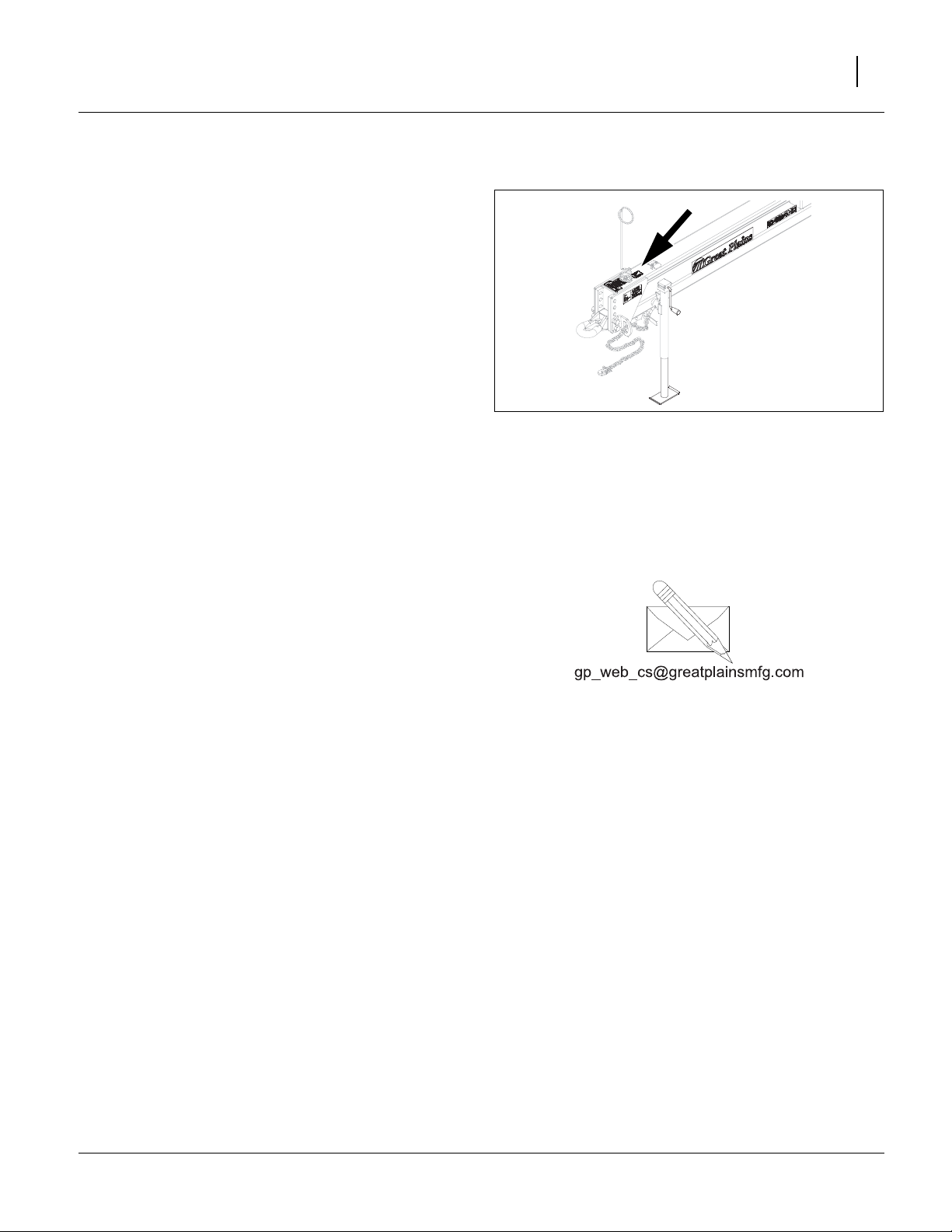
Refer to Figure 2
Your machine’s parts were specially designed and
should only be replaced with Great Plains specified
parts. Always use the serial and model number when
ordering parts from your Great Plains dealer. The serialnumber plate is located on the top face of the tongue,
near the hitch.
Record your Flex Harrow model and serial number here
for quick reference:
Model Number:__________________________
Serial Number: __________________________
Your Great Plains dealer wants you to be satisfied with
your new machine. If you do not understand any part of
this manual or are not satisfied with the service received,
please take the following actions.
1. Discuss the matter with your dealership service
manager. Make sure they are aware of any problems
so they can assist you.
2. If you are still unsatisfied, seek out the owner or general manager of the dealership.
Figure 2
Serial Number Plate
For further assistance write to:
Product Support
Great Plains Mfg. Inc., Service Department
PO Box 5060
Salina, KS 67402-5060
42319
785-823-3276
04/28/2014 564-070M

12 FH6000HD Great Plains Manufacturing, Inc.
Preparation and Setup
This section helps you prepare your tractor and
FH6000HD Flex Harrow for use, and covers tasks that
need to be done seasonally, or when the tractor/flex harrow configuration changes.
Before using the harrow in the field, you must hitch it to a
suitable tractor or leading implement, inspect systems
and unfold the harrow. Before using the flex harrow for
the first time, and periodically thereafter, certain adjustments may be required.
Initial Setup
See “Appendix B - Initial Setup” on page 35 for firsttime/infrequent setup tasks, including:
• Hitch Configuration (page 35).
• Tooth Angle (page 37).
• Install wing extensions (page 39).
• Install 4 bar drag extensions (page 40).
Post-Delivery/Seasonal Setup
On initial delivery, and seasonally, check and as necessary, complete these items before continuing to the routine setup items:
• Bleed hydraulic system (page 28).
• De-grease exposed cylinder rods if so protected at last
storage.
Pre-Application Setup
Complete this checklist before routine setup:
❑ Read and understand “A.Important Safety Informa-
tion” on page 1.
❑ Check that all working parts are moving freely, bolts
are tight, and cotter pins are spread.
❑ Check that all grease fittings are in place and lubri-
cated. See “Lubrication and Scheduled Mainte-
nance” on page 29.
❑ Check that all safety decals and reflectors are cor-
rectly located and legible. Replace if damaged. See
“Safety Decals” on page 5.
❑ Inflate tires to pressure recommended and tighten
wheel bolts as specified. See “Tire Inflation & War-
ranty” on page 33.
564-070M 04/28/2014

Great Plains Manufacturing, Inc. Preparation and Setup 13
Hitching Harrow to Tractor
Hitch to a tractor for highway transport or field operations. Hitch to a leading implement only for field operations. Do not transport behind another implement.
Before hitching, check the compatibility and capability of
the towing tractor or implement:
• The flex harrow is a pull-type implement equipped with
a standard Category IV single tang hitch. It may be
converted to a Category III or clevis hitch using supplied accessory parts (see “Hitch Configuration” on
page 35).
• Tongue weight varies from 500 pounds to 2300
pounds, depending on harrow model. See “Specifica-
tions and Capacities”, pages 32 to 33.
• Recommended tractor horsepower is 3 hp per foot of
implement width (72 to 162 hp, depending on harrow
model). This is in addition to the power required for
any leading implement.
• A leading implement must pass through one hydraulic
circuit.
Refer to Figure 3
1. Use jack to raise and lower harrow tongue.
2. Back tractor draw bar into alignment with hitch.
3. Secure with a locking hitch pin .
1
2
Crushing Hazard:
Do not stand or place any body part between harrow and moving tractor. You may be severely injured or killed by being
crushed between the tractor and harrow. Stop tractor engine
and set parking brake before attaching cables and hoses.
2
Negative Tongue Weight Hazard:
Make certain that harrow is securely hitched to the tractor or
leading implement before unfolding. An unhitched harrow can
tip over backwards during folding and unfolding if the tongue
is not secured.
4. Secure safety chain to an anchor on the tractor.
5. Retract jack foot. Re-orient jack to storage position.
6. After hitching tractor to harrow, store jack on storage
stob on flex harrow tongue.
1
1
Tongue Hitched
Figure 3
31664
04/28/2014 564-070M

14 FH6000HD Great Plains Manufacturing, Inc.
Electrical Hookup
Refer to Figure 4
Your flex harrow is equipped with lights.
Plug the lighting connector into the tractor outlet.
Test the lights and signalling prior to highway movement.
Hydraulic Hose Hookup
High Pressure Fluid Hazard:
Shut down tractor before making hydraulic connections.
Only trained personnel should work with system hydraulics.
Escaping fluid under pressure can have sufficient pressure to
penetrate the skin causing serious injury. If an accident
occurs, seek immediate medical assistance from a physician
familiar with this type of injury.
Use paper or cardboard, NOT BODY PARTS, to check for
leaks. Wear protective gloves and safety glasses or goggles
when working with hydraulic systems.
Refer to Figure 5
To distinguish hoses on the same hydraulic circuit, refer
to hose label.
• The hose with an extended-cylinder symbol feeds a
cylinder base end.
• The hose with a retracted-cylinder symbol feeds a cylinder rod end.
Secure hoses and cables so that they have sufficient
slack for hitch movements, but cannot get caught
between moving parts of tractor, harrow or hitch. Failure
to safely route and secure hoses and cables could result
in damage requiring component repair/replacement, and
lost field time.
Figure 4
Lighting Connector
Figure 5
Hose Handles
25236
31733
564-070M 04/28/2014

Great Plains Manufacturing, Inc. 15
Operating Instructions
This section covers general operating procedures. Experience, machine familiarity, and the following information
will lead to efficient operation and good working habits.
Always operate farm machinery with safety in mind.
Pre-Start Checklist
Perform the following steps before transporting the flex
harrow to the field.
This checklist presumes that the nurse tank is not yet
connected.
❑ Carefully read “A.Important Safety Information”on
page 1.
❑ Lubricate flex harrow as indicated under “Lubrica-
tion and Scheduled Maintenance” on page 29.
❑ Check all tires for proper inflation. See “Tire Infla-
tion & Warranty” on page 33.
❑ Check all bolts, pins, and fasteners. Torque as
shown in “Torque Values Chart” on page 34.
❑ Check flex harrow for worn or damaged parts. Repair
or replace parts before going to the field.
❑ Check hydraulic hoses, fittings, and cylinders for
leaks. Repair or replace before going to the field.
High Pressure Fluid Hazard:
Relieve pressure and shut down tractor before connecting, disconnecting or checking hydraulic lines. Use a piece of paper
or cardboard, NOT BODY PARTS, to check for leaks. Wear
protective gloves and safety glasses or goggles when working
with hydraulic systems. Escaping fluid under pressure can
have sufficient pressure to penetrate the skin causing serious
injury. If an accident occurs, seek immediate medical assistance from a physician familiar with this type of injury.
04/28/2014 564-070M

16 FH6000HD Great Plains Manufacturing, Inc.
Unfold Harrow
The Flex Harrow has a single hydraulic circuit that combines the lateral (wing) and vertical (harrow) unfolding
operations. During unfold, the wings first fully unfold, and
then the harrows lower to the ground.
1. Position the hitched and folded harrow on the field to
be worked, or on suitable other ground. Unfolding
brings the tines into ground contact, and some forward movement is required to lay the sections flat.
2. Double-check that the harrow is securely hitched to
the tractor or leading implement.
Refer to Figure 6
3. Lift the transport chain off the wing pin on both
1
wings.
4. Start the tractor. Set the brakes. Operate the engine
at low rpms.
Refer to Figure 7
5. Slowly extend the fold circuit. Wings unfold (swing
back). Do not move the tractor until the wings are
fully unfolded.
6. As wings reach fully unfolded, release the brakes.
Figure 6
Transport Chain
1
31665
Negative Tongue Weight Hazard:
Allow no one near or especially behind the unfolding implement. During unfold the tongue weight shifts from positive to
temporarily negative. If the hitch fails or there is a hydraulic
failure, the harrow can tip over backwards or the harrows can
fall suddenly. Anyone under them could be seriously injured or
killed.
Refer to Figure 8
7. As sections begin to fold down, pull forward.
8. When the sections are on the ground, continue to
extend the fold circuit until the cylinders are fully
extended.
Figure 7
Wings Unfolding
Figure 8
Sections Lowering
31666
31667
564-070M 04/28/2014

Great Plains Manufacturing, Inc. Operating Instructions 17
Refer to Figure 9
9. When the cylinders are at full extension on level
ground, the clevis pin is approximately in the center
of the slot. This allows for up and down travel over
unlevel ground.
Equipment Damage Risk:
Fully extend the cylinders. If they are at less than full extension, the cylinders or frame could be damaged.
The implement is now ready for field operations
(page 20).
Figure 9
Cylinder at Full Extension
Figure 10
Sections Lowered
31669
31668
04/28/2014 564-070M

18 FH6000HD Great Plains Manufacturing, Inc.
Fold
Negative Tongue Weight Hazard:
Allow no one near or especially behind the folding implement.
During fold the tongue weight shifts from positive to temporarily negative. If the hitch fails or there is a hydraulic failure,
the harrow can tip over backwards or the harrows can fall suddenly. Anyone under them could be seriously injured or killed.
Refer to Figure 11
1. With tractor engine at low rpms, slowly retract the
fold circuit.
Equipment Damage Risk:
Do not move the harrow until folding is complete. Movement
when partially folded can damage wings or center frame.
Refer to Figure 12
2. As the wings begin to fold forward, check that the
spring-operated cable lift arms are lifting the
cables .
Note: Harrows smaller than 30 feet do not use cables.
2
1
Figure 11
Sections Folding Up
31670
Equipment Damage Risk:
Stop the fold if the arms are not lifting the cables. If the arms
are not lifting the cables, the arms and wings may collide. The
wings may also not seat correctly for transport.
3. Continue retracting cylinders until the wings are fully
against the stops on the transport cross-tube. Hook
transport chains over pins on wings.
4. Harrow is now ready for transport (page 19), parking
(page 21) or storage (page 21).
3
1
3
Figure 12
Wings Folding In
2
31671
564-070M 04/28/2014

Great Plains Manufacturing, Inc. Operating Instructions 19
Transport
Loss of Control Hazard:
Do not tow the harrow behind another implement on public
roads. Tow the harrow to the field with a separate vehicle. The
leading implement may not provide sufficient lateral control of
a trailing implement at highway speeds. The total weight of the
train can also exceed the steering and/or braking capability of
the tractor. The resulting accident could cause serious injury
or death.
Loss of Control Hazard:
Use an adequate towing vehicle. Never tow an implement that
weighs more than 150% of the towing vehicle (transport vehicle must weigh at least 67% of implement). Ensure that the
towing vehicle is adequate for the task. Using an inadequate
tow vehicle is extremely unsafe, and can result in loss of control, serious injury and death.
See tables below for harrow transport weights.
Braking and Loss of Control Hazard:
Do not exceed 20 mph (32 kph). Slow down on rough roads.
Harrow Transport Weights
Model
Weight Range
Model
Weight Range
FH6424HD FH6630HD FH6636HD FH6642HD
4,050 - 4,550 lbs 5,000 - 5,650 lbs 6,000 - 6,450 lbs 6,200 - 6,700 lbs
1830 - 2060 kg 2270 - 2570 kg 2720 - 2930 kg 2810 - 3040 kg
FH6845HD FH6848HD FH6851HD
6,250 - 7,250 lbs 6,700 - 7,700 lbs 7,100 - 8,300 lbs
2840 - 3280 kg 3030 - 3500 kg 3210 - 3760 kg
Transport Steps
Know your implement weight. If tractor capabilities are
marginal, check actual weight of implement at a scale.
1. Check that implement is securely hitched to a sufficient tractor (page 13).
2. Always use a locking-style hitch pin sized to match
holes in hitch and draw-bar, and rated for the load.
3. Attach safety chain to tractor with enough slack to
permit turning (page 13).
4. Verify correct operation of lights.
5. Fold flex harrow (page 18).
6. Hook transport chains (page 18).
7. Check that tires are properly inflated (page 33).
8. Plan the route. Avoid steep hills.
9. Always have lights on for highway operation.
10. Do not exceed 32 kph (20 mph). Comply with all
national, regional and local laws when traveling on
public roads.
11. Remember that the implement may be wider than
the towing vehicle. Allow safe clearance.
12. Transport slowly over uneven or rough terrain.
04/28/2014 564-070M

20 FH6000HD Great Plains Manufacturing, Inc.
Field Operation
This implement is designed to be pulled in the field with
the harrows on the ground at all times (including turns).
Pulling for extended distances with sections lifted, or routine lifting for turns, is not recommended. Lifting for short
distances to clear residue clogs is acceptable. Lifting for
tight turns or reverse moves is required.
Equipment Damage Risk:
Do not pull for extended distances when partially raised.
Do not routinely raise for turns. Such practices cause premature wear of cylinders, pins and frame components. Such wear
is not covered by the warranty.
Equipment Damage Risk:
Lift for tight turns and reverse moves. Tight turns can result in
a section moving backward. Never back up with harrows on
the ground. If the inside tire stops or rolls backward, the turn is
tight and requires lift.
Field Set-Up Checklists
Use the following tables to develop a final checklist for
your tractor/flex harrow configuration. Additional or fewer
steps may be necessary depending on tractor features,
flex harrow options and planting accessories.
Mechanical Checklist (Tractor Hitching) Page
Flex Harrow hitched 13
Hitch pin locked
Safety chain secured to tractor or leading
implement
Parking jack stowed 13
Electrical Checklist Page
Verify electrical hookups solid, or connector securely stowed if not using lights in
field.
Hydraulic System Checklist Page
Check tractor hydraulic reservoir full -
Make hydraulic connections 14
Inspect connections for leaks -
Unfold Implement 19
13
14
564-070M 04/28/2014

Great Plains Manufacturing, Inc. Operating Instructions 21
Short-Term Parking
1. Choose an implement parking location with level firm
ground. Do not unhitch on a steep slope.
2. Fold harrow (page 19).
3. Engage transport lock chains (page 16)
4. Install jack stand on tongue (page 13).
5. Use parking jack to neutralize tongue weight at tractor hitch.
6. Set hydraulic circuits to neutral.
7. Disconnect hydraulic lines. Secure them so that they
do not touch the ground.
8. Disconnect lighting connector, capping where provisioned.
9. Disconnect safety chain.
10. Unhitch. Restart tractor and pull away from flex harrow.
Figure 13
Harrow Parked
31748
Long-Term Storage
1. Clean flex harrow of mud, dirt, excess oil and grease.
2. Lubricate all points listed in Maintenance.
3. Apply grease to exposed cylinder rods to prevent
rust.
4. Inspect flex harrow for worn or damaged parts. Make
repairs and service during off season.
5. Use spray paint to cover scratches, chips, and worn
areas on the flex harrow to protect the metal.
6. Park implement per “Short-Term Parking” above.
04/28/2014 564-070M

22 FH6000HD Great Plains Manufacturing, Inc.
Adjustments
To get full performance from your FH6000HD flex harrow, you need an understanding of all component operations. There are adjustments for optimal folding and field
results.
Adjustment Page The Adjustment Affects
Hitch Configuration 35 Compatibility with tractor or leading implement
Tooth Angle 37 Aggressive tine setting for unusual conditions
Wing Fold Height Adjustment 22 Proper wing folding as machine ages
FH6424HD to FH6642HD 22
FH6845HD to FH6854HD 23
Wing Fold Height Adjustment
Refer to Figure 14
As pins seat and wear, wings may droop, and fail to slide
easily onto support cross-member during fold.
Note: Models FH6424HD (24 foot) and FH6427HD
(27 foot) do not have a support cross-member.
In normal operation, the wing engages at about
1
⁄2in (13mm) below the top of the ramp of the wing
support cross-member.
1
2
FH6424HD to FH6642HD Wing Fold Height
On 12- and 16-bar harrows up to 42-foot, wing height is
adjusted by a stop bolt at each wing pivot lug.
Refer to Figure 15
Adjust the fold height by rotating the stop bolt head
(one for each wing).
When the adjustment is complete, inhibit bolt rotation by
applying silicone sealer to the exposed threads.
3
3
4
2
1
Figure 14
Wing at Support Cross-Member
3
4
31750
Figure 15
FH6400/6600HD Wing Height
564-070M 04/28/2014
31751

Great Plains Manufacturing, Inc. Adjustments 23
FH6845HD to FH6851HD Wing Fold Height
Refer to Figure 16
On harrows 45-foot and wider, wing fold height is
adjusted by a shim stack , on a threaded base weldment, at each wing fold pivot.
The initial (factory or dealer) adjustment does not require
all of the shims provided. Extra shims are stored in the
Manual-Pak®1 enclosure if there is sufficient room.
Refer to Figure 17
The maximum shim stack for each wing is 1
(4.76cm), provided as:
Quantity 1 564-166D 1” SHIM FH FOLD STOP
Quantity 2 564-098D SHIM 1/4"
Quantity 2 564-099D SHIM 1/8"
Quantity 2 564-132D SHIM 1/16"
To adjust wing fold height, remove the bolts and lock
washers . Add or remove shims to obtain the necessary lug stop height. Re-install bolts and washers.
Use the thickest shim at the top of the stack.
Refer to Figure 17
To adjust wing fold height, so the wing engages at the
correct position on the support cross-member (approximately
may need added or removed from the rear of the fold
stop.
The maximum shim stack for each wing is3⁄4in (19mm),
provided as:
Quantity 2 564-164D 1/4” SHIMS FH FOLD STOP
Quantity 2 564-165D 1/8” SHIMS FH FOLD STOP
Remove bolts , washers , and hex nuts , add or
remove shims to obtain the necessary fold height. Reinstall bolts, washers, and nuts.
42
43
44
108
74
1
⁄2in (13mm) below the top of the ramp), shims
112
113
52 74 114
5
7
⁄8in
55
55
74
43
108
5
Figure 16
FH6800HD Wing Height
42
52
44
43282
114
74
113
112
Equipment Damage Risk:
It is critical that when folded both the left and right clevis on
the center wing section are resting on the shim stack . Also
the center wing section needs to rest against the rear of the
fold stop.
1. Manual-Pak® is a registered trademark of Custom-Pak, Inc.
04/28/2014 564-070M
5
FH6800HD Wing Height Shims
Figure 17
43283

24 FH6000HD Great Plains Manufacturing, Inc.
FH6636 to FH6851HD Wing Adjustment
Refer to Figure 18
On harrows 36-foot and wider, wing adjustment cables
have been installed to keep the wings in line with the
1
front of the center section. This is done by moving the
clevis bolt in or out by adjusting the jam nuts . The
clevis bolt will move towards the center setion to allow
the wings to move backwards, or away from the center
section to bring the wings forward.
2 3
1
3
2
Figure 18: FH6600/6800HD
Wing Adjustments
43388
564-070M 04/28/2014

Great Plains Manufacturing, Inc. 25
Troubleshooting
General Implement Troubleshooting
Problem Cause Solution
Trailing Chains Lifting
Bars on Uneven Ground
Harrow Sections Hopping
Wings Hang up in Fold
Sections Gapping Inside
Wings or Center
Cylinders not fully extended Extend cylinders
Tooth angle too aggressive for speed Slow down or use 40° tooth angle. See
“Tooth Angle” on page 37.
Fold height needs adjustment See “Wing Fold Height Adjustment” on
page 22.
Chain broken or missing between
trailing bars of section
Replace chain, and as needed, harrow
teeth that secure chain.
04/28/2014 564-070M

26 FH6000HD Great Plains Manufacturing, Inc.
Maintenance and Lubrication
Maintenance
Proper servicing and maintenance is the key to long
implement life. With careful and systematic inspection,
you can avoid costly maintenance, downtime, and repair.
Always turn off and remove the tractor key before making
any adjustments or performing any maintenance.
Crushing Hazard:
Always fully unfold or use stands when working on implement.
You may be severely injured or killed by being crushed under a
falling implement.
High Pressure Fluid Hazard:
Check all hydraulic lines and fittings before applying pressure.
Fluid escaping from a very small hole can be almost invisible.
Use paper or cardboard, not body parts, and wear heavy
gloves to check for suspected leaks. Escaping fluid under pressure can have sufficient pressure to penetrate the skin. If an
accident occurs, seek immediate medical assistance from a
physician familiar with this type of injury.
1. After using your flex harrow for several hours, check
all bolts to be sure they are tight.
2. Maintain proper air pressure in tires.
3. Clean flex harrow on a regular basis. Regular and
thorough cleaning will lengthen equipment life and
reduce maintenance and repair.
4. Lubricate areas listed under “Lubrication and
Scheduled Maintenance” on page 29.
5. Replace any worn, damaged, or illegible safety
labels by obtaining new labels from your Great
Plains dealer.
564-070M 04/28/2014

Great Plains Manufacturing, Inc. Maintenance and Lubrication 27
Hydraulic Maintenance
As with any hydraulic system, contamination is the most
common cause of performance problems and premature wear. Make a special effort to properly clean
quick couplers prior to attaching the hoses to tractor, and
never let them fall to the ground.
High Pressure Fluid Hazard:
Relieve pressure before disconnecting hydraulic lines.Wear
protective gloves and safety glasses or goggles when working
with hydraulic systems. Use a piece of paper or cardboard,
NOT BODY PARTS, to check for suspected leaks. Escaping
fluid under pressure can penetrate the skin, causing serious
injury. If an accident occurs, seek immediate medical assistance from a physician familiar with this type of injury.
Bleed only at JIC and NPT fittings.
Never try to bleed a QD (Quick Disconnect) fitting.
Avoid bleeding at ORB fittings. The O-ring is likely to be
torn if any pressure remains in the circuit.
Crushing Hazard:
When reconnecting fittings at fold cylinder ports, verify that a
0.063in (1⁄16in, 1.6mm) orifice plate (Great Plains part number
196-430D) is installed at each port. A missing plate could
result in a dangerously fast unfold, which might result in
equipment damage, injury or death.
System Contamination Risk:
Always use liquid pipe sealant when adding or replacing NPT
(National Pipe Thread, tapered thread) pipe-thread fittings. To
avoid cracking hydraulic fittings from over tightening, and to
keep tape fragments from clogging filters, do not use plastic
sealant tape.
Over-Torque and Leak Risks:
JIC (Joint Industry Conference 37° Flare) fittings do not
require high torque. Excess torque causes leaks. JIC and
ORB (O-Ring Boss) fittings do not require sealant.
JIC Torque Chart
Size Foot-Pounds N-m
7
⁄16-20 11-12 15-16
1
⁄2-20 15-16 20-22
5
⁄16-18 18-20 24-28
3
⁄4-16 38-42 52-58
7
⁄8-14 57-62 77-85
11
⁄16-12 79-87 108-119
04/28/2014 564-070M

28 FH6000HD Great Plains Manufacturing, Inc.
Bleeding Hydraulics
Normally the hydraulics are bled during final pre-delivery,
and bleeding should not be required prior to first use.
Bleeding may be required after hydraulic maintenance,
or if the hydraulic system is in an uncertain state.
1. Hitch the harrow to a tractor.
2. If the harrow is folded, verify that the wing lock
chains are engaged (page 16).
3. Connect the hydraulics to a hydraulic source, such
as a tractor remote.
4. Set the source circuit to Float to relieve any pressure
in the lines.
5. Disconnect both base and rod ends of all fold cylinders.
6. Support the cylinders with ports facing up, and with
cylinders oriented so that rods cannot strike implement parts when at full extension.
7. Orient cylinders with base ends higher than rod
ends. Set circuit to Neutral.
One cylinder at a time:
8. Crack (slightly loosen) a JIC connection at a cylinder
base end.
9. Extend the circuit slowly until fluid appears at the fitting.
10. Set the circuit to Neutral. Tighten the fitting.
11. Repeat step 8 through step 10 for the remaining cylinders.
12. Retract the cylinders. Set circuit to Neutral.
13. Orient cylinders with rod ends higher than base
ends.
One cylinder at a time:
14. Crack (slightly loosen) a JIC connection at a cylinder
rod end.
15. Extend the circuit slowly until fluid appears at the fitting.
16. Set the circuit to Neutral. Tighten the fitting.
17. Repeat step 14 through step 16 for the remaining
cylinders.
18. Set circuit to Float.
19. Re-pin base and rod ends of cylinders to center section and wing lugs.
20. Test fold function carefully (page 16).
Negative Tongue Weight Hazard:
Make certain that harrow is securely hitched to a tractor
before unfolding. An unhitched harrow can tip over backwards
during folding and unfolding if the tongue is not secured.
Crushing and Equipment Damage Hazards:
Bleed after servicing cylinders or their hoses. Air in the system
makes it hazardous to fold the implement. If it is necessary to
service hydraulics while folded, the first unfold is especially
dangerous. Wing motion can be uneven or jerky in fold.
Unfolding wings could fall suddenly. Anyone nearby could be
seriously injured or killed. Equipment damage is likely.
High Pressure Fluid Hazard:
Wear safety goggles and gloves. The bleed procedure requires
partially opening pressurized hydraulic lines. Escaping fluid
under pressure can penetrate the skin, causing serious injury.
If an accident occurs, seek immediate medical assistance from
a physician familiar with this type of injury.
564-070M 04/28/2014

Great Plains Manufacturing, Inc. Maintenance and Lubrication 29
Lubrication and Scheduled Maintenance
Intervals
Multipurpose
spray lube
Multipurpose
grease lube
Multipurpose
oil lube
Inspection
required
(service hours)
50
at which lubrication
is required
Wing Hinges
4 zerks each pin,
1 pin per wing;
8 zerks total
Type of Lubrication: Grease
Quantity: Until grease emerges
Wing Pivots
3 zerks each pin,
6 zerks total
Type of Lubrication: Grease
Quantity: Until grease emerges
42734
8
31641
8
Tire Pressures
20
4 tires in two sizes
See page 33 for tire pressures.
Check tire pressures more frequently on a new implement, and with new tires. Check tire pressures before
making any level adjustments, and whenever there are
application problems.
04/28/2014 564-070M
31642

30 FH6000HD Great Plains Manufacturing, Inc.
Wheel Hubs, Transport
Seasonal
(pull-type implements only)
1 zerk each hub,
4 hubs per implement;
4 zerks total
Type of Lubrication: Grease
Quantity: Until resistance is felt
31642
Wheel Hubs, Wing
Seasonal
(pull-type implements only)
1 zerk each hub,
4 hubs per implement;
4 zerks total
Type of Lubrication: Grease
Quantity: Until resistance is felt
31787
564-070M 04/28/2014

Great Plains Manufacturing, Inc. 31
Options
Wing Extensions
These kits add a one tooth extension assembly to
each side of the harrow, increasing the total working
width by 1
standard harrows) includes 24 extension assemblies.
The 16 row (bar) kit (for harrows with row extensions)
includes 32.
1
⁄2ft (18in, 46cm). The 12 row (bar) kit (for
19
Kit Description
1 1/2 FT 12 ROW EXT KIT 564-048A
1 1/2 FT 16 ROW EXT KIT 564-049A
Order one kit per harrow. These extensions are fieldinstalled. See instructions on page 40.
Row Extensions
These kits add a 4 bar extension to every section of the
intended harrow model. Kits are specific to individual
harrow models, as bar length combinations are different
for each model. Kits include fasteners for connection to
the rear end of the existing 12th bar.
Kit Description Option Part No.
FH6424 4 ROW EXT KIT 20 564-059A
FH6630 4 ROW EXT KIT 20 564-061A
FH6636 4 ROW EXT KIT 20 564-063A
FH6642 4 ROW EXT KIT 20 564-065A
FH6845 4 ROW EXT KIT 20 564-066A
FH6848 4 ROW EXT KIT 20 564-067A
FH6851 4 ROW EXT KIT 20 564-068A
Order one Option or kit per harrow. If ordered with the
original harrow purchase (Option), these extensions are
factory- or dealer-installed. For field installation, see
page 39.
19
31774
31786
04/28/2014 564-070M

32 FH6000HD Great Plains Manufacturing, Inc.
Appendix A - Reference Information
Specifications and Capacities
Model FH6400HD Specifications and Capacities
Model
Working Width (Swath)
Tooth Size
Tooth Spacing
Teeth Per Foot of Width
Field Length
Field Width (Span)
Transport Height (Folded)
Transport Width
Transport Length
Transport Clearance
Weight Range
Tongue Weight
Hitch
Tractor Power Required¹
1. Power requirements vary significantly with conditions and practices.
6 inch (15.2 cm), plus 2½in (6.4 cm) thread, diamond-shaped forge-hardened
9 in. tooth-to-tooth, 11 in. bar-to-bar, 12 bars standard (16 optional)
16.0 (Standard 12 bar), 21.3 (Optional 16 bar)
4,050 - 4,550 lbs (1830 - 2060 kg)
Category IV; Category III or Clevis with included accessories
Model FH6600HD Specifications and Capacities
Model
Working Width (Swath)
Tooth Size
Tooth Spacing
Teeth Per Foot of Width
Field Length
Field Width (Span)
Transport Height (Folded)
Transport Width
Transport Length
Transport Clearance
Weight Range
Tongue Weight
Hitch
Tractor Power Required¹
1. Power requirements vary significantly with conditions and practices.
FH6630HD FH6636HD FH6642HD
30ft. 0in. (9.14 m) 36ft. 0in. (10.97 m) 42ft. 0in. (12.80 m)
6 inch (15.2 cm), plus 2½in (6.4 cm) thread, diamond-shaped forge-hardened
9 in. tooth-to-tooth, 11 in. bar-to-bar, 12 bars standard (16 optional)
16.0 (Standard 12 bar), 21.3 (Optional 16 bar)
38ft. 0in. (11.58 m) 38ft. 0in. (11.58 m) 38ft. 0in. (11.58 m)
31ft. 6in. (9.60 m) 37ft. 6in. (11.43 m) 43ft. 6in. (13.26 m)
10ft. 10in. (3.30 m) 10ft. 10in. (3.30 m) 10ft. 10in. (3.30 m)
12ft. 8in. (3.86 m) 12ft. 8in. (3.86 m) 12ft. 8in. (3.86 m)
22ft. 0in. (6.71 m) 22ft. 0in. (6.71 m) 22ft. 0in. (6.71 m)
11.3 in. (28.6 cm) 11.3 in. (28.6 cm) 11.3 in. (28.6 cm)
5,000 - 5,650 lbs 6,000 - 6,450 lbs 6,200 - 6,700 lbs
2270 - 2570 kg 2720 - 2930 kg 2810 - 3040 kg
600 lbs (270 kg) 820 lbs (370 kg) 1,200 lbs (540 kg)
Category IV; Category III or Clevis with included accessories
90 - 140 hp 110 - 170 hp 125 - 195 hp
65 - 105 kW 80 - 125 kW 95 - 145 kW
FH6424HD
24ft. 0in. (7.32 m)
38ft. 0in. (11.58 m)
25ft. 6in. (7.77 m)
10ft. 10in. (3.30 m)
12ft. 8in. (3.86 m)
22ft. 0in. (6.71 m)
11.3 in. (28.6 cm)
480 lbs (220 kg)
70 - 100 hp (55 - 75 kW)
564-070M 04/28/2014

Great Plains Manufacturing, Inc. Appendix A - Reference Information 33
Model FH6800HD Specifications and Capacities
Model
Working Width (Swath)
Tooth Size
Tooth Spacing
Teeth Per Foot of Width
Field Length
Field Width (Span)
Transport Height (Folded)
Transport Width
Transport Length
Transport Clearance
Weight Range
Tongue Weight
Hitch
Tractor Power Required¹
1. Power requirements vary significantly with conditions and practices.
FH6845HD FH6848HD FH6851HD
45ft. 0in. (13.72 m) 48ft. 0in. (14.63 m) 51ft. 0in. (15.54 m)
6 inch (15.2 cm), plus 2½in (6.4 cm) thread, diamond-shaped forge-hardened
9 in. tooth-to-tooth, 11 in. bar-to-bar, 12 bars standard (16 optional)
16.0 (Standard 12 bar), 21.3 (Optional 16 bar)
42ft. 0in. (12.80 m) 42ft. 0in. (12.80 m) 42ft. 0in. (12.80 m)
46ft. 6in. (14.17 m) 49ft. 6in. (15.09 m) 52ft. 6in. (16.00 m)
10ft. 10in. (3.30 m) 10ft. 10in. (3.30 m) 10ft. 10in. (3.30 m)
12ft. 8in. (3.86 m) 12ft. 8in. (3.86 m) 12ft. 8in. (3.86 m)
26ft. 0in. (7.92 m) 26ft. 0in. (7.92 m) 26ft. 0in. (7.92 m)
11.3 in. (28.6 cm) 11.3 in. (28.6 cm) 11.3 in. (28.6 cm)
6,250 - 7,250 lbs 6,700 - 7,700 lbs 7,100 - 8,300 lbs
2840 - 3280 kg 3030 - 3500 kg 3210 - 3760 kg
1,580 lbs (710 kg) 1,680 lbs (760 kg) 2,180 lbs (990 kg)
Category IV; Category III or Clevis with included accessories
135 - 210 hp 145 - 220 hp 155 - 235 hp
100 - 155 kW 105 - 165 kW 115 - 175 kW
Tire Inflation & Warranty
Tire Inflation Chart
Wheel Tire Size Inflation
Transport
Wing
12.5Lx15 SL
12-Ply
30x8.8x15
16-Ply Aircraft
52 psi
(360 kPa)
60 psi
(415 kPa)
Tire Warranty Information
All tires are warranted by the original manufacturer of the tire.
Tire warranty information is found in the brochures included with
your Operator’s and Parts Manuals or online at the manufacturer’s web sites listed below. For assistance or information, contact your nearest Authorized Farm Tire Retailer.
Manufacturer Web site
Firestone www.firestoneag.com
Gleason www.gleasonwheel.com
Titan www.titan-intl.com
Galaxy www.atgtire.com
BKT www.bkt-tire.com
04/28/2014 564-070M

34 FH6000HD Great Plains Manufacturing, Inc.
T
Torque Values Chart
Bolt
Size
in-tpi
1
⁄4-20
1
⁄4-28
5
⁄16-18
5
⁄16-24
3
⁄8-16
3
⁄8-24
7
⁄16-14
7
⁄16-20
1
⁄2-13
1
⁄2-20
9
⁄16-12
9
⁄16-18
5
⁄8-11
5
⁄8-18
3
⁄4-10
3
⁄4-16
7
⁄8-9
7
⁄8-14
1-8
1-12
1
1
⁄8-7
1
1
⁄8-12
1
⁄4-7
1
1
⁄4-12
1
3
⁄8-6
1
3
1
⁄8-12
1
1
⁄2-6
1
1
⁄2-12
Bolt Head Identification
Grade 2 Grade 5 Grade 8 Class 5.8 Class 8.8 Class 10.9
a
b
d
N-m
ft-lb
7.4 11 16
8.5 13 18
15 24 33
17 26 37
27 42 59
31 47 67
43 67 95
49 75 105
66 105 145
75 115 165
95 150 210
105 165 235
130 205 285
150 230 325
235 360 510
260 405 570
225 585 820
250 640 905
340 875 1230
370 955 1350
480 1080 1750
540 1210 1960
680 1520 2460
750 1680 2730
890 1990 3230
1010 2270 3680
1180 2640 4290
1330 2970 4820
N-m N-m
5.6 8 12
61014 5 811
11 17 25 12 19 27
13 19 27 13 21 29
20 31 44 24 39 53
22 35 49 29 45 62
32 49 70 42 67 93
36 55 78 44 70 97
49 76 105 66 77 105
55 85 120 68 105 150
70 110 155 73 115 160
79 120 170 105 165 230
97 150 210 115 180 245
110 170 240 145 230 300
170 265 375 165 260 355
190 295 420 205 325 450
165 430 605 230 480 665
185 475 670 355 560 780
250 645 910 390 610 845
275 705 995 705 1120 1550
355 795 1290 785 1240 1710
395 890 1440 1270 1950 2700
500 1120 1820 1380 2190 3220
555 1240 2010
655 1470 2380
745 1670 2710
870 1950 3160
980 2190 3560
Bolt Head Identification
Bolt
Size
ft-lb ft-lb ft-lb ft-lb ft-lb
mm x pitch
M 5 X 0.8
M 6 X 1
M 8 X 1.25
M 8 X 1
M10 X 1.5
M10 X 0.75
M12 X 1.75
M12 X 1.5
M12 X 1
M14 X 2
M14 X 1.5
M16 X 2
M16 X 1.5
M18 X 2.5
M18 X 1.5
M20 X 2.5
M20 X 1.5
M24 X 3
M24 X 2
M30 X 3.5
M30 X 2
M36 X 3.5
M36 X 2
a. in-tpi = nominal thread diameter in inches-threads per inch
b. N· m = newton-meters
c. mm x pitch = nominal thread diameter in mm x thread pitch
d. ft-lb = foot pounds
c
5.8 8.8 10.9
N-m N-m N-m
357
71115
17 26 36
18 28 39
33 52 72
39 61 85
58 91 125
60 95 130
90 105 145
92 145 200
99 155 215
145 225 315
155 240 335
195 310 405
220 350 485
280 440 610
310 650 900
480 760 1050
525 830 1150
960 1510 2100
1060 1680 2320
1730 2650 3660
1880 2960 4100
946
orque tolerance + 0%, -15% of torquing values. Unless otherwise specified use torque values listed above.
25199m
25199
Wheel Bolt Torque Values 1/2”-20 (75-85 ft-lbs) 9/16”-18 (80-90 ft-lbs) 5/8”-18 (85-100 ft-lbs)
564-070M 04/28/2014

Great Plains Manufacturing, Inc. 35
Appendix B - Initial Setup
This Appendix covers setup tasks performed only once,
or at infrequent intervals. Routine setup tasks are covered in “Preparation and Setup” on page 12. Perform
Appendix B tasks first. Some of these items may already
have been done by your Great Plains dealer:
a. Configure hitch (below and page 36)
b. Configure tine angle (page 37).
c. Install options not dealer-installed:
Install Row Extensions (page 39)
Install Wing Extensions (page 40)
Hitch Configuration
The standard FH6000HD hitch is a Category IV
single tang. The FH6000HD includes components for
converting the hitch to clevis or to Category III.
Great Plains recommends operating with the tongue
level with the ground. Machine operation is relatively
unaffected by hitch height, but the hitch must be matched
to the tractor or towing implement.
Each hitch configuration (Category IV, Category III and
clevis) requires a specific orientation of the base hitch.
93
Post-Delivery Checklist
1. Read and understand “A.Important Safety Information” on page 1.
2. Check that all working parts are moving freely, bolts
are tight, and cotter pins are spread.
3. Check that all grease fittings are in place and lubricated. See “Lubrication and Scheduled Mainte-
nance” on page 29.
4. Check that all safety decals and reflectors are correctly located and legible. Replace if damaged. See
“Safety Decals” on page 5.
5. Inflate tires to pressure recommended and tighten
wheel bolts as specified. See “Tire Inflation & War-
ranty” on page 33.
66
77
11
93
Hitch Height or Hitch Inversion
1. Remove and save two sets of:
803-031C NUT HEX 1-8 PLT
66
804-027C WASHER LOCK SPRING 1 PLT
77
802-877C HHCS 1-8X9 GR8 SPTHD
45
and one each:
891-189C HITCH BASE - CAT IV
93
556-236D SAFETY CHAIN SUPPORT
11
2. Orient the hitch as required for the hitch type
(upright, recessed notch down for Category IV), and
position it at the height desired.
3. Re-secure the chain support and hitch with both
bolts . Use both bolts. Secure through 2 holes in
45
chain support, 4 holes in tongue lugs and 2 holes in
hitch casting .
04/28/2014 564-070M
93
11
93
Hitch Failure Risk:
Verify that there are TWO grade 8 bolts through:
TWO holes in chain support ,
FOUR holes in tongue lugs, and
TWO holes in hitch casting .
If any of these components is secured by only a single bolt,
machine damage is likely. The hitch could fail entirely, causing
a highway accident resulting in serious injury or death.
45
Figure 19
Adjust Hitch
11
93
42057
45

36 FH6000HD Great Plains Manufacturing, Inc.
Clevis Hitch
Refer to Figure 20
The base hitch must be upright (with the recessed notch
on the bottom) for this configuration. This places the
tongue weight on the base hitch, and not the clevis.
1. Select one each:
890-798C HITCH CLEVIS
92
802-487C HHCS 3/4-10X6 GR8
58
803-367C NUT HEX TOP LOCK 3/4-10 PLT
72
2. With the square-shouldered end of the clevis up,
fully seat the clevis in the upright base hitch .
Insert the Grade 8 bolt from below. Secure with
lock nut .
72
58
92
93
72
92
58
Hitch Failure Hazard:
Install the hitch base and assemble the clevis parts as shown.
Incorrect installation or assembly may result in failure of the
clevis bolt, leading to hitch failure. This could result in a serious highway accident or severe machine damage.
93
Category III Hitch
The base hitch must be inverted (with the recessed
notch on the top) for this configuration. Set the
V-block to allow some vertical articulation of the draw
bar pin. Always use at least one cushion .
1. Select one each:
2. Set the cushions inside the hitch recess , just for-
3. Add the top plate . Secure from below with
97
98
PPI-302V TOP PLATE - CAT 3
99
PPI-203VR V-BLOCK
97
802-383C HHCS 3/4-10X3 GR5
57
and two:
PPI-205H CUSHION
98
98
ward of the vertical bolt hole. Position the V-block
97
forward of the cushions and check the size of the
resulting pinning hole. Remove a cushion if needed.
99
Grade 5 bolt .
57
99
98
97
57
Figure 20
Configure Hitch
31740
42057
31741
564-070M 04/28/2014

Great Plains Manufacturing, Inc. Appendix B - Initial Setup 37
Tooth Angle
Refer to Figure 21
Tine tooth angle is set by the tooth angle plate .
The tine teeth are factory-set with the sharp break
side toward the direction of motion ( ).
1
This pulls the teeth at 40° off vertical (50° relative to the
ground). This angle is suitable for most conditions, has
no speed restrictions, usually creates a more optimal
seedbed, and provides easier residue flow.
For a more aggressive tine angle of 22° off vertical (68°
relative to the ground), reverse all harrow sections at
their chain connection to the arms.
Excess Wear / Irregular Results Risks:
Do not exceed 41⁄2 mph (7.2 kph) with tines at 22°.
Machine loads are much higher.
Tine sections may also hop on the ground.
To change tine angle:
38
1
38
40°
Spot Implement
1. With the harrow directly hitched to a tractor (not to
another implement), fully unfold the implement in
field conditions (page 16). Allow enough room for the
tractor to approach either end of the harrow sections.
Pull forward to lay the sections flat on the ground.
Disconnect/Move Leading Chains
Refer to Figure 22
2. Disconnect the trailing end of the leading chains
from the harrow sections. Remove and save only the
lock nut:
803-019C NUT LOCK 1/2-13 PLT
64
it is re-installed at step 6.
Refer to Figure 22 and Figure 23
3. Disconnect the leading ends of the leading chains
from the section frame. Remove fasteners:
802-722C HHCS 9/16-12X3 1/2 GR5 ZNYCR
61
803-319C NUT HEX TOP LOCK 9/16-12 ZNYCR
70
Re-attach them at the other frame hole.
Use the upper hole for the 22° tooth angle.
Use the lower hole for the [standard] 40° tooth angle.
40
40
70
22°
Figure 21
Tooth Angles
61
Figure 22
Disconnect Leading Chain
22°
40°
31746
40
64
31648
40
Tighten nuts only until bolt does not rotate freely.
Relocate Leading Chain
04/28/2014 564-070M
Figure 23
31756

38 FH6000HD Great Plains Manufacturing, Inc.
Disconnect Trailing Chains
Refer to Figure 24
4. Exchange bolts and move jam nut at pull tabs
between the front and middle section (bars / ),
and between middle and rear section (bars / ).
Move the longer bolt and jam nut:
802-128C HHCS 1/2-13X2 GR5
54
803-036C NUT HEX JAM 1/2-13 PLT
67
from the current chain position to the tabs at / .
Insert bolt from below at / tabs and secure with
jam nut only.
Move the shorter bolt:
802-091C HHCS 1/2-13X1 1/2 GR5
52
from the tabs at / to the tabs at / .
Insert bolt from above and secure with lock nut:
803-019C NUT LOCK 1/2-13 PLT
64
Save one lock nut for chain attachment at step 7.
5. When all harrow sections are disconnected, reposition the implement (without harrows) at the other end
of the harrows.
4 5 8 9
4 5
4 5
8 9
4 5
52
64
5
4
Figure 24
Disconnect Trailing Chain
64
67
9
8
54
31648
54
Reconnect Leading Chains
Refer to Figure 25
6. Place free chain bolt through top of now-leading
tab . Pull chain forward and secure with saved lock
95
nut:
803-019C NUT LOCK 1/2-13 PLT
64
54
95
64
Figure 25
Reconnect Leading Chain
31648
Reconnect Trailing Chains
Refer to Figure 26
7. Place the trailing link of the trailing chain over the
new bar / bolt . Pull chain forward and secure
with saved lock nut:
64
8 954
803-019C NUT LOCK 1/2-13 PLT
39
39
64
9
54
8
Figure 26
Disconnect Trailing Chain
564-070M 04/28/2014
31648

Great Plains Manufacturing, Inc. Appendix B - Initial Setup 39
Install Row Extensions
Refer to Figure 27 (depicting 4.5ft drags)
A complete kit of 4 bar drag extensions may include a
combination of up to three different widths of drag
assemblies:
564-042L 4 1/2 FT 4 ROW DRAG EXT
14
564-044L 6 FT 4 ROW DRAG EXT
16
564-046L 7 1/2 FT 4 ROW DRAG EXT
18
See Pre-Delivery manual for drag identification.
1. Set a drag extension ( , or ) that is the same
14 16 18
width as an existing 12 row drag on the implement.
2. Remove and save two sets of bolts and nuts from the
drag extension:
803-019C NUT LOCK 1/2-13 PLT
64
802-091C HHCS 1/2-13X1 1/2 GR5
52
3. Align the pull tabs of the extension under the trailing
tabs of the rear-most drag bar. Make sure that the
tooth angle plates are in the same orientation on
38
the drag extension as on the main drag. See
Figure 21 on page 37 for details on tooth angle.
4. Secure pull tabs with bolts and nuts .
52 64
5. Repeat step 1 through step 4 for all drag sections.
Refer to Figure 28
Move linking chains starting with the center wing.
6. At bar 12 of the linked drags, remove the teeth
803-342C NUT HEX TOP LOCK 1/2-13 PLT
71
891-238C HARROW TOOTH - 8 1/2" DIAMOND
96
securing the linking chain
564-092D CHAIN 5/16 HIGH TEST 8 LINKS
41
between the drag sections.
7. Re-install the teeth at row 12 without the
chain . Tighten nuts only to Grade 2 torque
41 71
96
specification, to avoid crushing the tubes.
8. Re-install the chain between the same drag sec-
41
tions at row 16.
9. To make a chain connection, remove the end set of:
803-342C NUT HEX TOP LOCK 1/2-13 PLT
71
891-238C HARROW TOOTH - 8 1/2" DIAMOND
96
10. Insert an end link of the chain in the trailing tube. On
one end, twist the chain
1
⁄4turn to align the end link
with the tube hole.
11. Reinstall the tooth . Tighten nut only to Grade 2
96 71
torque specification, to avoid crushing tube.
12. Repeat step 6 through step 11 for all other drag sections with linking chains. Some configurations have
only center wing linking chains.
38
Disconnect Trailing Chain
96
Machine Damage Risk:
Do NOT link drag sections from wing to wing. The chains
are not long enough to accommodate the distance required for
wing folding.
41
Figure 27
71
Figure 28
Relocate Linking Chain
52
14
64
38
31772
41
31771
41
04/28/2014 564-070M

40 FH6000HD Great Plains Manufacturing, Inc.
Install Wing Extensions
Refer to Figure 29
Two kits are available that extend the working width of
the harrow by 18in:
564-048A 1 1/2 FT 12 ROW EXT KIT
564-049A 1 1/2 FT 16 ROW EXT KIT
These kits contain, respectively, 24 or 32 sets of:
564-047K 1 1/2 FT EXTENSION ASSY
19
These mount to the outside ends of the wing bar
tubes .
1
Repeat for all 24 or 32 wing end bar tubes:
1. Remove and save one set:
803-342C NUT HEX TOP LOCK 1/2-13 PLT
71
891-238C HARROW TOOTH - 8 1/2" DIAMOND
96
2. Select one:
564-047K 1 1/2 FT EXTENSION ASSY
19
Insert the vacant end of the extension tube into the
bar tube , and align the holes, with the tooth pointing down.
3. Re-install the removed tooth and nut , using
them to secure the extension tube . Tighten nut
only to Grade 2 torque specification.
1
96 71
19 71
96
1
Figure 29
Install Wing Extensions
71
1
19
31774
564-070M 04/28/2014

Great Plains Manufacturing, Inc. Appendix B - Initial Setup 41
Warranty
Great Plains Manufacturing, Incorporated warrants to the original purchaser that this tillage
and workmanship for a period of one year from the date of original purchase when used as intended and under normal service and conditions
for personal use; 90 days for commercial or rental purposes. This Warranty is limited to the replacement of any defective part by Great Plains
Manufacturing, Incorporated and the installation by the dealer of any
such replacement part. Great Plains reserves the right to inspect any
equipment or part which are claimed to have been defective in material
or workmanship.
This Warranty does not apply to any part or product which in Great
Plains’ judgement shall have been misused or damaged by accident or
lack of normal maintenance or care, or which has been repaired or altered in a way which adversely affects its performance or reliability, or
which has been used for a purpose for which the product is not designed. This Warranty shall not apply if the product is towed at a speed
in excess of 20 miles per hour.
Claims under this Warranty must be made to the dealer which originally
sold the product and all warranty adjustments must by made through
such dealer. Great Plains reserves the right to make changes in materials or design of the product at any time without notice.
This Warranty shall not be interpreted to render Great Plains liable for
damages of any kind, direct, consequential, or contingent, to property.
Furthermore, Great Plains shall not be liable for damages resulting from
any cause beyond its reasonable control. This Warranty does not extend to loss of crops, losses caused by harvest delays or any expense
or loss for labor, supplies, rental machinery or for any other reason.
No other warranty of any kind whatsoever, express or implied, is
made with respect to this sale; and all implied warranties of merchantability and fitness for a particular purpose which exceed
the obligations set forth in this written warranty are hereby disclaimed and excluded from this sale.
This Warranty is not valid unless registered with Great Plains Manufacturing, Incorporated within 10 days from the date of original purchase.
equipment will be free from defects in material
42134
04/28/2014 564-070M

42 FH6000HD Great Plains Manufacturing, Inc.
564-070M 04/28/2014

Great Plains Manufacturing, Inc. 43
Index
A
address, Great Plains ...................... 11
adjustments ...................................... 22
amber reflectors ................................. 6
angle, tooth ...................................... 37
B
bleeding, fold .................................... 28
C
cable ................................................ 18
capacities ......................................... 32
Category III .....................13
Category IV ............................. 13
CAUTION, defined ............................. 1
chain ................................................ 13
chain, transport ....................... 16
checklists
electrical ..................................... 20
field ............................................. 20
hydraulic system ........................ 20
mechanical
implement ............................. 20
pre-setup ........................... 12
pre-start ...................................... 15
children .............................................. 2
clevis hitch .............................. 35
contact Great Plains ......................... 11
covered models ................................ 10
cushion ............................................. 36
customer service .............................. 11
cylinder extension ............................ 17
cylinder symbols .............................. 14
, 35, 36
, 35
, 18
, 35
, 36
D
DANGER, defined .............................. 1
daytime reflectors ............................... 6
decal replacement .............................. 5
decals
caution
no step .................................... 8
read manual ........................... 8
danger
electrocution ........................... 6
hitch ........................................ 7
tip over .................................... 7
notice
tip over .................................... 9
warning
high pressure fluid hazard ...... 8
overhead wing ........................ 8
speed ...................................... 7
decal, safety ....................................... 5
definitions ......................................... 10
directions .......................................... 10
droop, wing ...................................... 22
E
email, Great Plains ........................... 11
extension, cylinder ........................... 17
extension, row ......................... 31
, 39
extension, wing ........................31
, 40
F
FH6400HD ....................................... 32
FH6424HD ............. 10
FH6427HD ....................................... 22
FH6600HD ....................................... 32
FH6630HD ......................10
FH6636 to FH6851HD Wing Adjustment
....................................................... 24
FH6636HD ......................10
FH6642HD ............. 10
FH6800HD ....................................... 33
FH6845HD ............. 10
FH6848HD ......................10
FH6851HD ............. 10
field operation .................................. 21
fire ...................................................... 1
fold height, wing ............................... 22
, 22, 31, 32
, 31, 32
, 31, 32
, 22, 31, 32
, 23, 31, 33
, 31, 33
, 23, 31, 33
H
handles, hose .................................. 14
HD ................................................... 10
height, wing fold ............................... 22
high pressure fluid ........................... 14
high pressure fluids ........................... 2
hills .................................................. 19
hitch ................................................. 35
hitch pin ........................................... 19
hitching ............................................ 13
horsepower ...................................... 13
hose handles ................................... 14
hoses, hydraulic ............................... 14
hydraulic bleed ................................. 27
hydraulic hoses ................................ 14
hydraulic safety .................................. 2
I
inflation ............................................ 33
intended usage ................................ 10
J
jack .................................................. 13
JIC torque ........................................ 27
Joint Industry Conference ................ 27
L
leading implement ........................... 13
leaks .................................................. 2
left-hand, defined ............................. 10
lift arm .............................................. 18
lifting ................................................ 20
lights ..........................................2
lower ................................................ 16
, 14
M
maintenance .................................... 26
hydraulic .................................... 27
maintenance safety ............................ 4
Manual-Pak ...................................... 23
Martens Manufacturing .................... 10
medical assistance .. 2
model number .................................. 11
, 14, 15, 26
N
National Pipe Thread ....................... 27
negative tongue weight 13
28
Note, defined .................................... 10
NOTICE, defined ..............................10
NPT .................................................. 27
NP30L ..............................................10
NP30L-11R30 .................................. 32
NP30L-12R30 .................................. 32
NP30L-13R30 .................................. 32
NP40L ..............................................10
NP40L-15R30 .................................. 32
, 16, 18,
O
optional .............................................10
option, defined ..................................10
ORB ................................................. 27
orientation rose ................................ 10
orifice plate .......................................27
O-Ring Boss .....................................27
owner assistance ............................. 11
P
paint ................................................. 21
parking ............................................. 21
phone number, GP ...........................11
pin, hitch ........................................... 19
plastic sealant tape .......................... 27
plate, orifice ......................................27
PPI-203VR, block .............................36
PPI-205H, cushion ...........................36
PPI-302V, plate ................................36
Q
QD .................................................... 27
quick coupler .................................... 27
Quick Disconnect .............................27
R
red reflectors ......................................5
reflectors
amber ...........................................6
daytime .........................................6
red ................................................5
SMV .............................................. 5
reflectors, safety .................................5
repair parts ....................................... 11
reverse .............................................20
riders ..................................................2
right-hand, defined ...........................10
rose, orientation ............................... 10
row extension .......................... 31
, 39
S
safety chain ............................... 2, 13
safety decal ........................................ 5
safety information ...............................1
safety symbol .....................................1
scale ................................................. 19
serial number ................................... 11
04/28/2014 564-070M

44 FH6000HD Great Plains Manufacturing, Inc.
setup ................................................ 12
initial ........................................... 12
pre-planting ................................ 12
seasonal ..................................... 12
shim stack ........................................ 23
shutdown ........................................... 3
SMV (Slow Moving Vehicle) ............... 5
specifications ................................... 32
speed limit
forward ....................................... 19
transport ..................................... 19
stop bolt ........................................... 22
storage ...................................... 3
support ............................................. 11
support cross-member ..................... 22
symbol, safety .................................... 1
, 21
T
tables
adjustments ................................ 22
document family ......................... 10
models covered .......................... 10
specifications ............................. 32
torque ......................................... 34
JIC ........................................ 27
troubleshooting
general ................................. 25
implement ............................. 25
tape, pipe ......................................... 27
tire inflation ...................................... 33
tire inflation & warranty .................... 33
tires .................................................... 3
tooth angle ....................................... 37
torque
fastener ...................................... 34
JIC .............................................. 27
towing .............................................. 19
towing vehicle capability .................. 19
tractor horsepower ........................... 13
transport ........................................... 19
transport chain ........................ 16
transport speed .................................. 3
troubleshooting
implement .................................. 25
, 18
turns .................................................20
U
unfold ................................................16
URLs, tires ........................................33
V
V-block ..............................................36
W
WARNING, defined ............................1
warranty .......................... 20
weight ...............................................19
weight, implement .............................19
welding ...............................................4
wing droop ........................................22
wing extension .........................31
wing fold height .................................22
www ..................................................33
, 33, 41
, 40
Numerics
12-Bar ...............................................10
12.5Lx15 SL .....................................33
13 mph ...............................................3
196-430D, orifice ..............................27
20 mph ...................................... 3
20, option ..........................................31
22 degrees ........................................37
22 kph .................................................3
30x8.8x15 .........................................33
32 kph .................................................3
40 degrees ........................................37
556-236D, support ............................35
564-000M, manual ............................10
564-042L, drag ext. ..........................39
564-044L, drag ext. ..........................39
564-046L, drag ext. ..........................39
564-047K, extension .........................40
564-048A, extension ................ 31
564-049A, extension ................ 31
564-059A, drag kit ............................31
564-061A, drag kit ............................31
564-063A, drag kit ............................31
564-065A, drag kit ............................31
564-066A, drag kit ............................31
564-067A, drag kit ............................31
, 19
, 40
, 40
564-068A, drag kit ............................ 31
564-070M, manual ...........................10
564-070P, manual ............................ 10
564-070Q, manual ........................... 10
564-092D, chain ............................... 39
564-097D, shim ................................ 23
564-098D, shim ................................ 23
564-099D, shim ................................ 23
6400HD ............................................ 10
6600HD ............................................ 10
6800HD ............................................ 10
802-091C, bolt ......................... 38
802-128C, bolt .................................. 38
802-383C, bolt .................................. 36
802-487C, bolt .................................. 36
802-722C, bolt .................................. 37
802-877C, bolt .................................. 35
803-019C, nut ................ 37
803-031C, nut .................................. 35
803-036C, nut .................................. 38
803-319C, nut .................................. 37
803-342C, nut ......................... 39
803-367C, nut .................................. 36
804-027C, washer ............................ 35
818-055C, SMV .................................. 5
818-337C, decal ................................. 7
818-398C, decal ................................. 8
838-094C, decal ................................. 8
838-598C, decal ................................. 8
838-599C, decal ................................. 6
838-600C, decal ................................. 7
838-602C, decal ................................. 8
838-603C, reflector ............................ 6
838-614C, reflector ............................ 5
838-615C, reflector ............................ 6
848-705C, decal ................................. 7
848-706C, decal ................................. 9
890-798C, clevis ............................... 36
891-189C, hitch ................................ 35
891-238C, tooth ...................... 39
, 39
, 38, 39
, 40
, 40
564-070M 04/28/2014


Great Plains Manufacturing, Inc.
Corporate Office: P.O. Box 5060
Salina, Kansas 67402-5060 USA
 Loading...