

Page 1
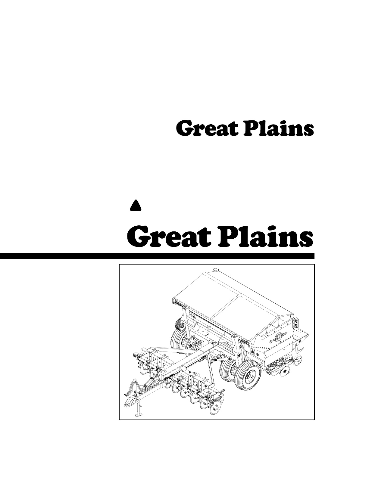
Operator’ s Manual
FCP1000
Three-Meter Drill and Hitch
Manufacturing, Inc.
www .g reatplainsmfg.com
Read the operator’s manual entirely. When you see this symbol, the subsequent in-
!
structions and warnings are serious- follow without exception. Your life and the lives of
others depend on it!
© Copyright 2004 Printed
7/5/2005
21895
Cover illustration may show optional equipment not supplied with standard unit.
148-693M-A
Rev. C
Page 2

Table of Contents
Table of Contents
Great Plains Mfg., Inc.
Important Safety Information . . . . . . . . . . . . . . . . . 1
Introduction . . . . . . . . . . . . . . . . . . . . . . . . . . . . . . . 8
Description of Unit. . . . . . . . . . . . . . . . . . . . . . . . 8
Intended Usage. . . . . . . . . . . . . . . . . . . . . . . 8
Using This Manual. . . . . . . . . . . . . . . . . . . . . . . . 8
Definitions . . . . . . . . . . . . . . . . . . . . . . . . . . . 8
Owner Assistance . . . . . . . . . . . . . . . . . . . . . . . . 8
Section 1 Preparation and Setup . . . . . . . . . . . . . . 9
Prestart Checklist . . . . . . . . . . . . . . . . . . . . . . . . 9
Wiring Drill. . . . . . . . . . . . . . . . . . . . . . . . . . . . . . 9
Hitching Tractor to Implement . . . . . . . . . . . . . . 10
Hydraulic Hook-up. . . . . . . . . . . . . . . . . . . . . . . 11
Bleeding Hydraulic Systems . . . . . . . . . . . . . . . 11
Bleeding Tongue Cylinder . . . . . . . . . . . . . . 11
Bleeding Transport Lift Cylinders . . . . . . . . 11
Bleeding Marker Hydraulics . . . . . . . . . . . . 12
Section 2 Operating Instructions . . . . . . . . . . . . . 13
Prestart Checklist . . . . . . . . . . . . . . . . . . . . . . . 13
Field Operation . . . . . . . . . . . . . . . . . . . . . . . . . 13
Opener Operation . . . . . . . . . . . . . . . . . . . . 13
Pivot Lock Tubes. . . . . . . . . . . . . . . . . . . . . 13
Marker Operation . . . . . . . . . . . . . . . . . . . . 14
Transport Lift Cylinders . . . . . . . . . . . . . . . . 14
Fertilizer Operation . . . . . . . . . . . . . . . . . . . . . . 14
Transporting. . . . . . . . . . . . . . . . . . . . . . . . . . . . 15
Parking . . . . . . . . . . . . . . . . . . . . . . . . . . . . . . . 15
Section 3 Adjustments . . . . . . . . . . . . . . . . . . . . . 16
Seeding Depth. . . . . . . . . . . . . . . . . . . . . . . . . . 16
Coulters. . . . . . . . . . . . . . . . . . . . . . . . . . . . 16
Openers . . . . . . . . . . . . . . . . . . . . . . . . . . . 16
Coulter Depth . . . . . . . . . . . . . . . . . . . . . . . . . . 16
Hydraulic Control. . . . . . . . . . . . . . . . . . . . . 16
Coulter Mounting Height . . . . . . . . . . . . . . . 17
Coulter Down Pressure . . . . . . . . . . . . . . . . . . . 17
Added Weight . . . . . . . . . . . . . . . . . . . . . . . 17
Coulter Springs . . . . . . . . . . . . . . . . . . . . . . 17
Opener Depth . . . . . . . . . . . . . . . . . . . . . . . . . . 18
Press Wheel Adjustment. . . . . . . . . . . . . . . 18
Opener Mounting Height. . . . . . . . . . . . . . . 18
Opener Down Pressure. . . . . . . . . . . . . . . . . . . 18
Disk Scraper Adjustment. . . . . . . . . . . . . . . . . . 18
Harrow Adjustment . . . . . . . . . . . . . . . . . . . . . . 19
Leaf Spring Adjustment. . . . . . . . . . . . . . . . . . . 19
Marker Adjustments. . . . . . . . . . . . . . . . . . . . . . 19
Folding Speed . . . . . . . . . . . . . . . . . . . . . . . 19
Disk Adjustments . . . . . . . . . . . . . . . . . . . . . 20
Pivot Lock Tube Adjustment. . . . . . . . . . . . . . . . 20
Seed-Lok Lock Up . . . . . . . . . . . . . . . . . . . . . . . 20
Setting the Seeding Rate . . . . . . . . . . . . . . . . . . 20
Changing Drive Sprockets . . . . . . . . . . . . . . 21
Setting Seed-Rate Handle . . . . . . . . . . . . . . 21
Positioning Seed-Cup Doors . . . . . . . . . . . . 21
Checking Seeding Rate . . . . . . . . . . . . . . . . 22
Seed Rate Charts . . . . . . . . . . . . . . . . . . . . . . . . . . 23
Fertilizer Rate Calibration. . . . . . . . . . . . . . . . . . 26
Fertilizer Meter Rate Charts . . . . . . . . . . . . . . . . 27
Density Conversion Chart . . . . . . . . . . . . . . 28
Small Seeds Attachment . . . . . . . . . . . . . . . . . . 29
Small Seed Rate Charts. . . . . . . . . . . . . . . . . . . 29
Section 4 Troubleshooting. . . . . . . . . . . . . . . . . . . 30
Section 5 Maintenance and Lubrication. . . . . . . . 32
Maintenance. . . . . . . . . . . . . . . . . . . . . . . . . . . . 32
Fertilizer Clean Out . . . . . . . . . . . . . . . . . . . 32
Transport Cylinder Support Brace . . . . . . . . 32
Storage. . . . . . . . . . . . . . . . . . . . . . . . . . . . . . . . 33
Lubrication . . . . . . . . . . . . . . . . . . . . . . . . . . . . . 33
Vertical Pivot Bushings, Top and Bottom . . . 33
Coulter Swing Arm Pivot . . . . . . . . . . . . . . . 34
Coulter Hub Bearings. . . . . . . . . . . . . . . . . . 34
Seed-Cup-Drive Sprocket . . . . . . . . . . . . . . 34
Tongue to Main Frame Pivot . . . . . . . . . . . . 34
Transport Wheel Bearings . . . . . . . . . . . . . . 35
Optional Folding Markers. . . . . . . . . . . . . . . 35
Additional Lubrication, Fertilizer Drills . . . . . 36
Section 6 Options . . . . . . . . . . . . . . . . . . . . . . . . . . 37
Harrow Attachment. . . . . . . . . . . . . . . . . . . . . . . 37
Markers. . . . . . . . . . . . . . . . . . . . . . . . . . . . . . . . 37
Mud Guard . . . . . . . . . . . . . . . . . . . . . . . . . . . . . 37
Acremeter. . . . . . . . . . . . . . . . . . . . . . . . . . . . . . 37
Seed-Cup Plugs . . . . . . . . . . . . . . . . . . . . . . . . . 38
Seed-Lok Firming Wheels . . . . . . . . . . . . . . . . . 38
Small Seeds Attachment . . . . . . . . . . . . . . . . . . 38
Section 7 Specifications and Capacities . . . . . . . 39
Appendix . . . . . . . . . . . . . . . . . . . . . . . . . . . . . . . . . 40
Tire Inflation Chart . . . . . . . . . . . . . . . . . . . . . . . 40
Torque Values Chart. . . . . . . . . . . . . . . . . . . . . . 40
Warranty. . . . . . . . . . . . . . . . . . . . . . . . . . . . . . . 41
© Copyright 2004 All rights Reserved
Great Plains Manufacturing, Inc. provides this publication “as is” without warranty of any kind, either expressed or implied. While every precaution has been taken in the preparation
of this manual, Great Plains Manufacturing, Inc. assumes no responsibility for errors or omissions. Neither is any liability assumed for damages resulting from the use of the information contained herein. Great Plains Manufacturing, Inc. reserves the right to revise and improve its products as it sees fit. This publication describes the state of this product at the
time of its publication,and may not reflect the product in the future.
The following are trademarks of Great Plains Mfg., Inc.: Application Systems, Ausherman, Land Pride, Great Plains, Seed-Lok
All other brands and product names are trademarks or registered trademarks of their respective holders.
FCP1000 Three-Meter Drill and Hitch 148-693M-A 7/5/2005
Great Plains Manufacturing, Incorporated T r ademarks
Printed in the United States of America.
Page 3
Great Plains Mfg., Inc.
Important Safety Information
Important Safety Information
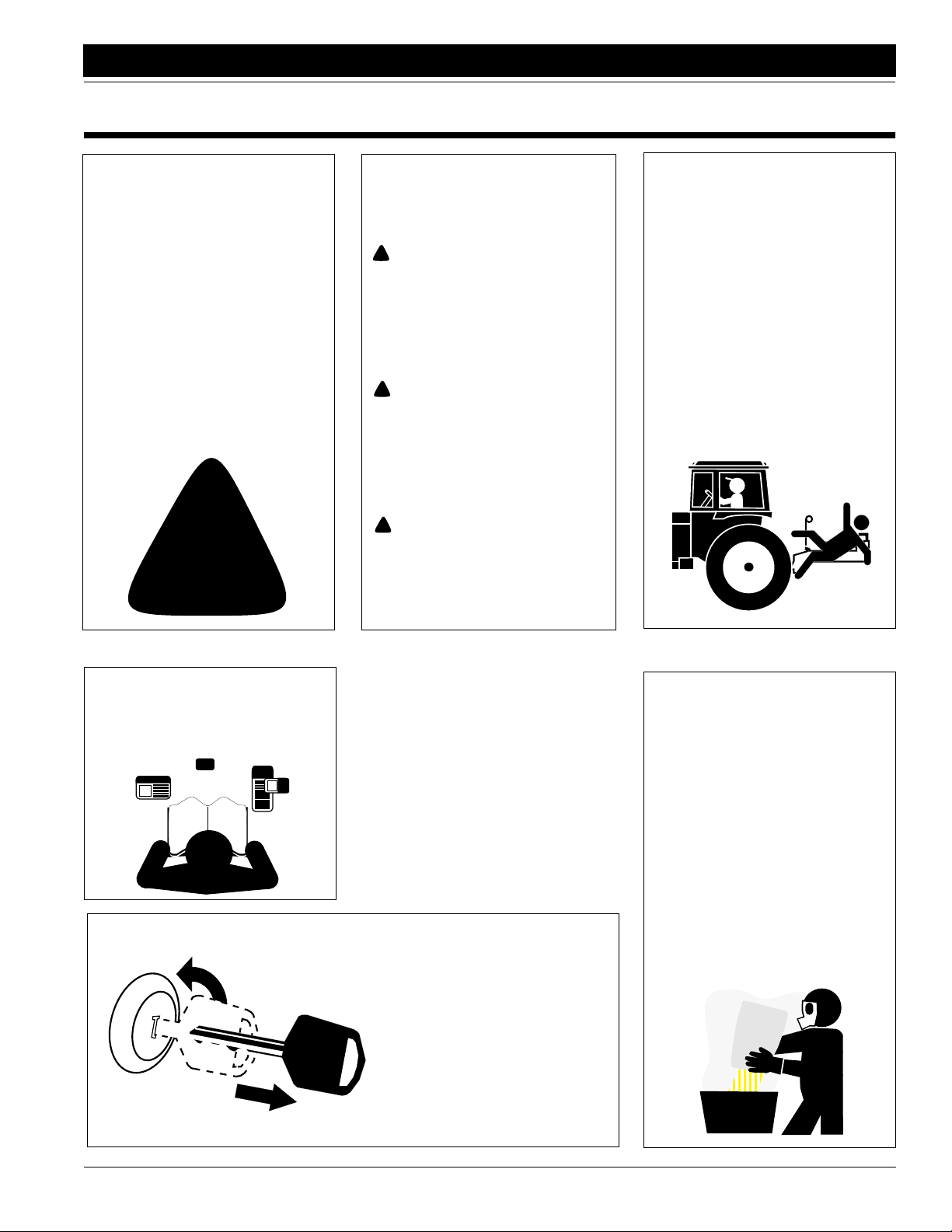
Look for Safety Symbol
The SAFETY ALERT SYMBOL indicates there is a potential hazard to
personal safety involved and extra
safety precaution must be taken.
When you see this symbol, be alert
and carefully read the message that
follows it. In addition to design and
configuration of equipment, hazard
control and accident prevention are
dependent upon the awareness,concern, prudence and proper training of
personnel involved in the operation,
transport, maintenance and storage
of equipment.
!
Be Aware of Signal Words
Signal words designate a degree or
level of hazard seriousness. The signal words are:
!
DANGER!
Indicates an imminently hazardous
situation which, if not avoided, will
result in death or serious injury. This
signal word is limited to the most
extreme situations, typically for
machine components that, for functional purposes, cannot be guarded.
!
WARNING!
Indicates a potentially hazardous situation which, if not avoided, could
result in death or serious injury, and
includes hazards that are exposed
when guards are removed. It may
also be used to alert against unsafe
practices.
!
CAUTION!
Indicates a potentially hazardous situation which, if not avoided, may
result in minor or moderate injury. It
may also be used to alert against
unsafe practices.
Keep Riders
Off Machinery
Riders obstruct the operator’s view.
Riders could be struck by foreign
objects or thrown from machine.
▲ Never allow riders on implement.
▲ Never allow children to operate
equipment.
For Your Protection
▲ Thoroughly read and understand
Safety Decals, page 4. Read all
instructions noted on decals.
OFF
Shutdown and Storage
▲ Lower machine to ground, put
tractor in park, turn off engine,
and remove key.
▲ Detach and store implement in an
area where children normally do
not play. Secure implement with
blocks and supports.
Handle
Chemicals Properly
Agricultural chemicals can be dangerous. Improper use can seriously
injure persons, animals, plants, soil
and property.
▲ Wear protective clothing.
▲ Handle all chemicals with care.
▲ Follow instructions on container
label.
▲ Avoid inhaling smoke from any
type of chemical fire.
▲ Store or dispose of unused chem-
icals as specified by chemical
manufacturer.
7/5/2005
FCP1000 Three-Meter Drill and Hitch 148-693M-A
1
Page 4
Important Safety Information
Great Plains Mfg., Inc.
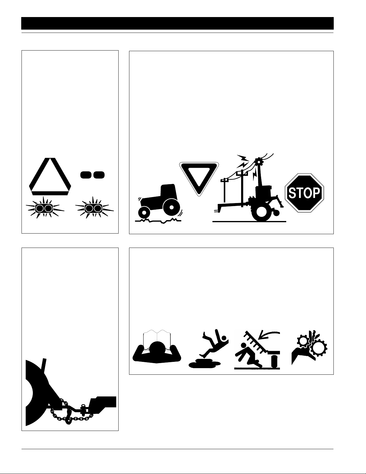
Use Safety
Lights and Devices
Slow-moving tractors, self-propelled
equipment and towed implements
can create a hazard when driven on
public roads. They are difficult to see,
especially at night.
▲ Use flashing warning lights and
turn signals whenever driving on
public roads.
▲ Use lights and devices provided
with implement.
Transport
Machinery Safely
Maximum transport speed for implement is 32 kph (20 mph). Some
rough terrains require a slower
speed. Sudden braking can cause a
towed load to swerve and upset.
▲ Do not exceed 32 kph (20 mph).
Never travel at a speed that does
not allow adequate control of
steering and stopping.
▲ Comply with state and local laws.
▲ Reduce speed if towed load is not
equipped with brakes.
▲ Do not tow an implement that,
when fully loaded, weighs more
than 1.5 times the weight of towing vehicle.
Use A Safety Chain
▲ Use a safety chain to help con-
trol drawn machinery should it
separate from tractor drawbar.
▲ Use a chain with a strength rat-
ing equal to or greater than
gross weight of towed machinery.
▲ Attach chain to tractor drawbar
support or other specified
anchor location. Allow only
enough slack in chain to permit
turning.
▲ Replace chain if any links or end
fittings are broken, stretched or
damaged.
▲ Do not use safety
chain for towing.
Practice Safe Maintenance
▲ Understand procedure before
doing work. Use proper tools and
equipment. Refer to this manual
for additional information.
▲ Work in a clean, dry area.
▲ Lower implement to ground, put
tractor in park, turn off engine,
and remove key before performing
maintenance.
▲ Allow implement to cool completely.
▲ Inspect all parts. Make sure parts
are in good condition and installed
properly.
▲ Remove buildup of grease, oil or
debris.
▲ Remove all tools and unused
parts from implement before operation.
FCP1000 Three-Meter Drill and Hitch 148-693M-A 7/5/2005
2
Page 5
Great Plains Mfg., Inc.
Important Safety Information
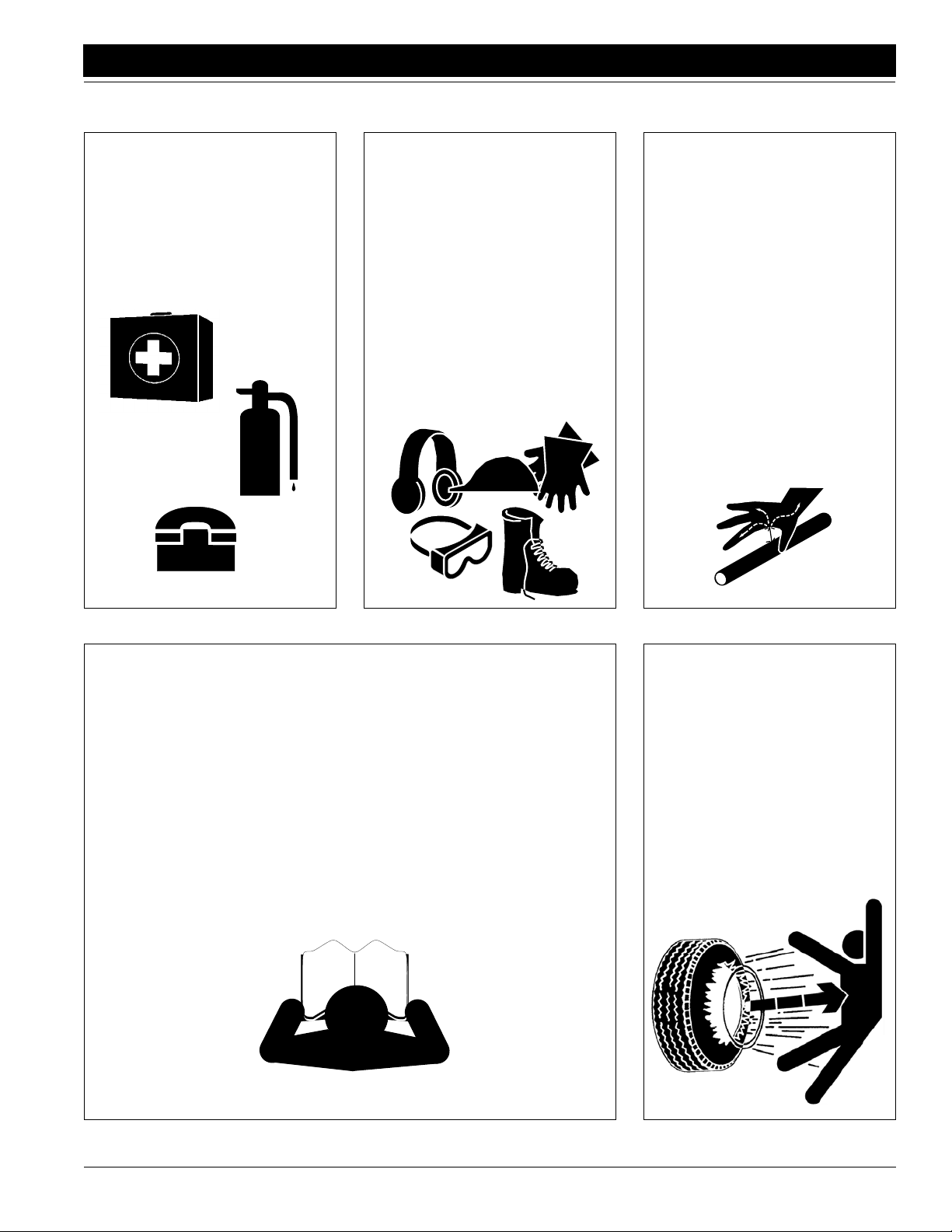
Prepare for Emergencies
▲ Be prepared if a fire starts.
▲ Keep a first-aid kit and fire extin-
guisher handy.
▲ Keep emergency numbers for
doctor, ambulance, hospital and
fire department near phone.
911
Wear
Protective Equipment
▲ Wear protective clothing and
equipment.
▲ Wear clothing and equipment
appropriate for the job. Avoid
loose-fitting clothing.
▲ Because prolonged exposure to
loud noise can cause hearing
impairment or hearing loss, wear
suitable hearing protection such
as earmuffs or earplugs.
▲ Because operating equipment
safely requires your full attention,
avoid wearing radio headphones
while operating machinery.
Avoid High
Pressure Fluids Hazard
Escaping fluid under pressure can
penetrate skin, causing serious
injury.
▲ Avoid the hazard by relieving
pressure before disconnecting
hydraulic lines.
▲ Use a piece of paper or card-
board, not body parts, to check for
suspected leaks.
▲ Wear protective gloves and safety
glasses or goggles when working
with hydraulic systems.
▲ If an accident occurs, see a doc-
tor immediately. Any fluid injected
into the skin must be surgically
removed within a few hours or
gangrene may result.
Safety at All Times
Thoroughly read and understand this
manual before operation. Refer to
Safety Decals,
instructions noted on decals.
▲ Be familiar with all implement
functions.
▲ Operate implement from driver’s
seat only.
▲ Do not leave tractor or implement
unattended with engine running.
▲ Do not dismount a moving tractor.
Dismounting a moving tractor could
cause serious injury or death.
page 4. Read all
▲ Do not stand between tractor and
implement during hitching.
▲ Keep hands, feet and clothing
away from power-driven parts.
▲ Wear snug-fitting clothing to avoid
entanglement with moving parts.
▲ Watch out for wires, trees, etc.,
when raising implement. Make
sure all persons are clear of working area.
▲ Do not turn tractor too tight, caus-
ing implement to ride up on
wheels. This could result in injury
or equipment damage.
Tire Safety
Tire changing can be dangerous and
should be performed by trained personnel using correct tools and equipment.
▲ When inflating tires, use a clip-on
chuck and extension hose long
enough to allow you to stand to
one side–NOT in front of or over
the tire assembly. Use a safety
cage if available.
▲ When removing and installing
wheels, use wheel-handling
equipment adequate for weight
involved.
7/5/2005
FCP1000 Three-Meter Drill and Hitch 148-693M-A
3
Page 6
Important Safety Information
Safety Decals
Your implement comes equipped with all safety decals in place.
They were designed to help you safely operate your implement.
1. Read and follow decal directions.
2. Keep all safety decals clean and legible.
3. Replace all damaged or missing decals. Order new decals
from your Great Plains dealer. Refer to this section for
proper decal placement.
Great Plains Mfg., Inc.
4. When ordering new parts or components, also request corresponding safety decals.
5. To install new decals:
a. Clean the area on which the decal is to be placed.
b. Peel backing from decal. Press firmly on surface,
being careful not to cause air bubbles under decal.
21895
17214
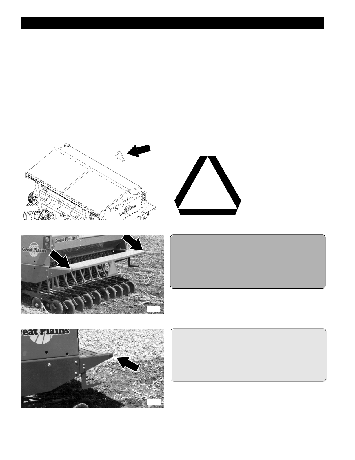
818-003C
Slow Moving Vehicle Label
On the back ofthe box,one
total
838-266C
Red Reflectors
Both ends of walkboard;
two decals total
838-265C
17862
FCP1000 Three-Meter Drill and Hitch 148-693M-A 7/5/2005
4
Amber Reflectors
Both ends of walkboard;
two decals total
Page 7
Great Plains Mfg., Inc.
Important Safety Information
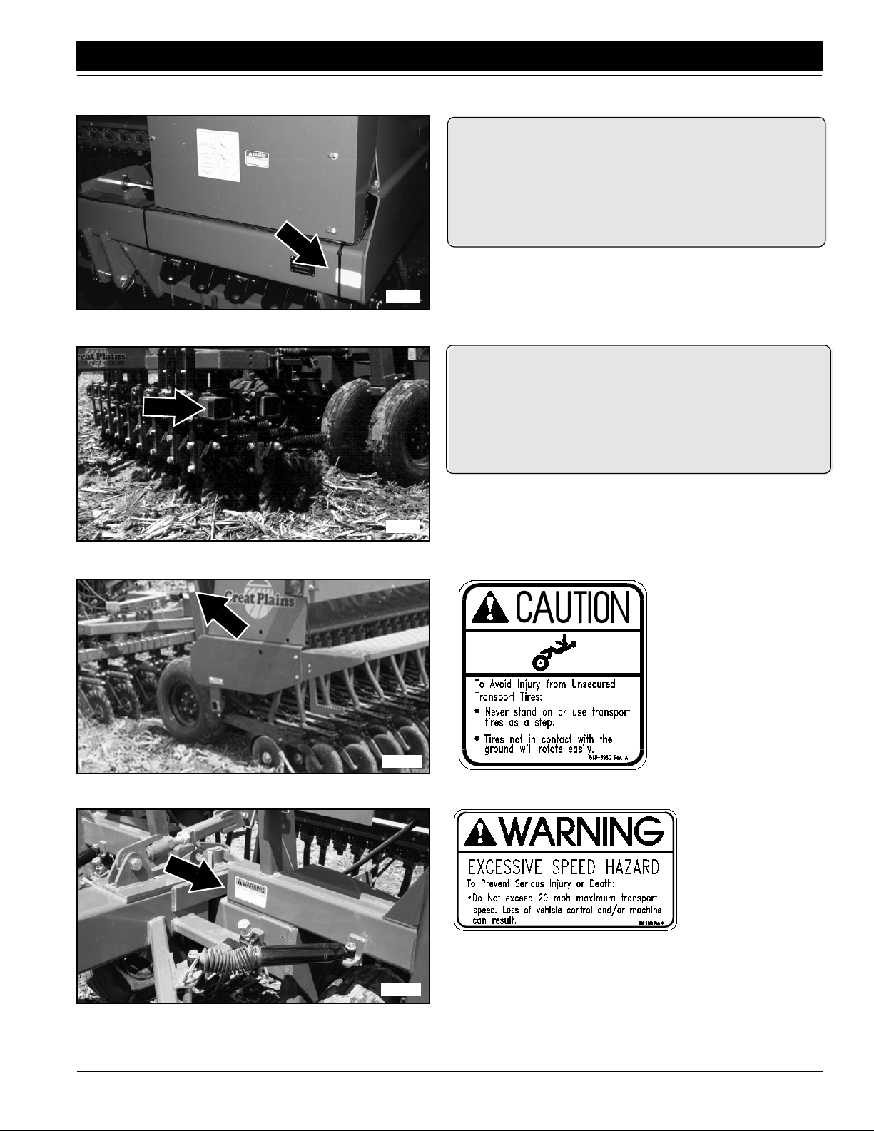
17858
838-265C
Amber Reflectors
Both ends of drill frame
tube; two decals total
17861
17206
838-265C
Amber Reflectors
Both ends of coulter tool-
bar; two decals total
818-398C
Caution–Tires Not a Step
Decal on each frame
post; two decals total
7/5/2005
17219
818-188C
Warning 20 MPH
Transport
FCP1000 Three-Meter Drill and Hitch 148-693M-A
5
Page 8
Important Safety Information
Great Plains Mfg., Inc.
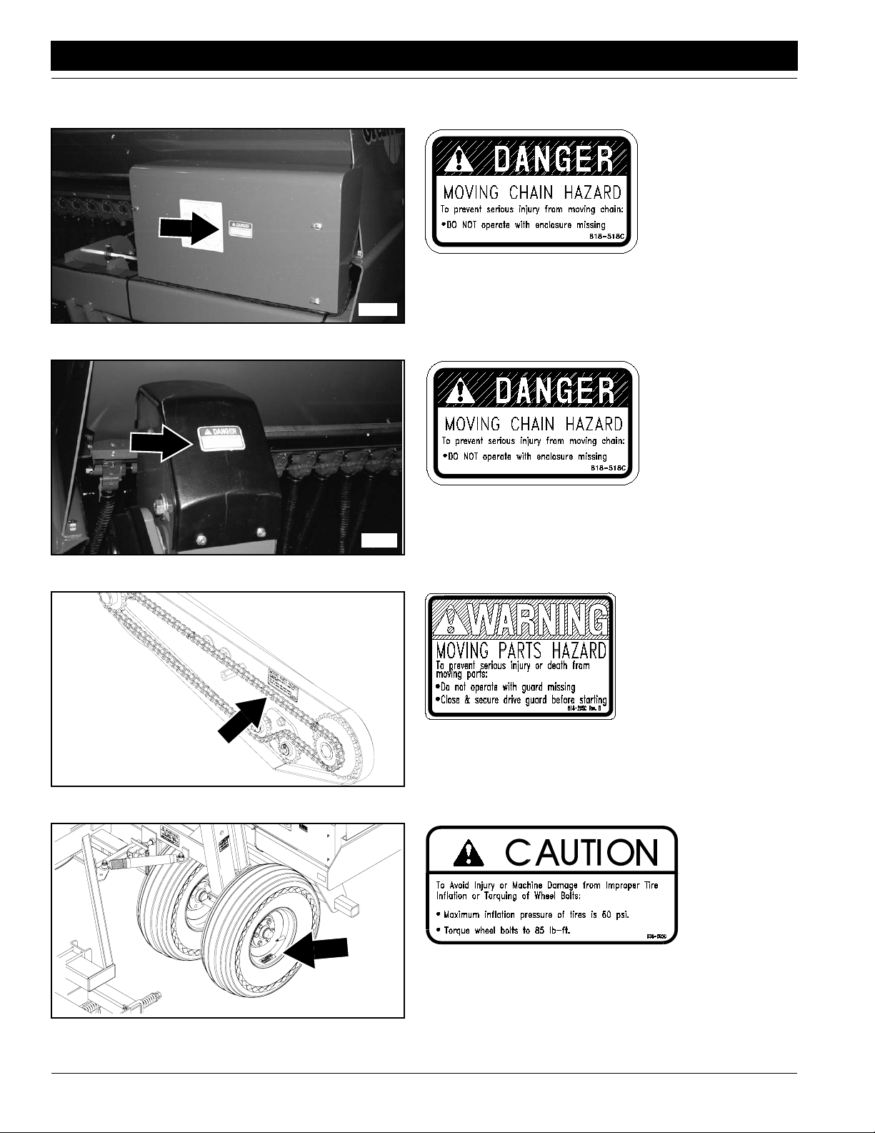
818-518C
Danger Moving Chain
17858
17865
818-518C
Danger Moving Chain
17859
818-205C
Warning Moving Parts
Hazard
838-092C
Caution Tire Inflation
17903
FCP1000 Three-Meter Drill and Hitch 148-693M-A 7/5/2005
6
One Per Gauge Wheel
Page 9
Great Plains Mfg., Inc.
Important Safety Information
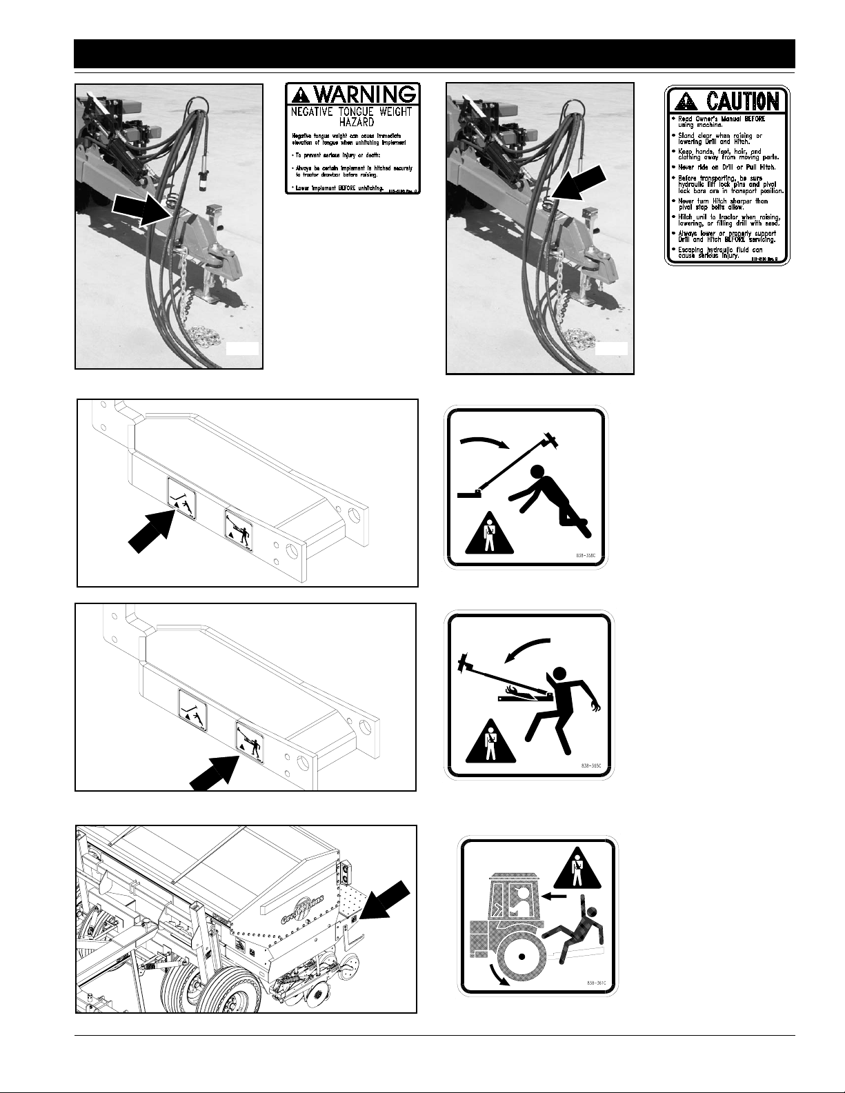
818-019C
Warning Neg Tongue
Weight
818-016C
Caution Pivot Pull
Hitch
21504
17209
21504
17209
838-367C
Warning Overhead Marker
One per marker
838-365C
Warning Pinch/Shear
One per marker
7/5/2005
21500
838-361C
Do Not Ride
One on each end of
walkboard
FCP1000 Three-Meter Drill and Hitch 148-693M-A
7
Page 10
Introduction
Introduction
Great Plains welcomes you to its growing family of new
product owners. This implement has been designed with
care and built by skilled workersusing quality materials.
Proper setup, maintenance and safe operating practices
will help you get years of satisfactory use from the
machine.
Description of Unit
The FCP1000 is a pull-type seeding implement. The
implement consists of a three-point drill mounted on a
centre-pivot hitch. The hitch and drill are integrallyconnected. No-till coulters are mounted on the hitch to zonetillstrips forseedfurrows.Straight-armopeners onthe drill
prepareseedbeds andplace the seed.The pivotingaction
of the hitch helps drill openers track the coulters. A contract-drive tire on the drill powers seeding off a hitch tire.
The tongue cylinder controls coulter depth and transport
cylinders raise the drill for turns and transport.
Intended Usage
Use this implement for seeding production-agriculture
crops only.Do not modify implement for use with attachments other than those specified by Great Plains. Use
implement in no or minimum tillage.
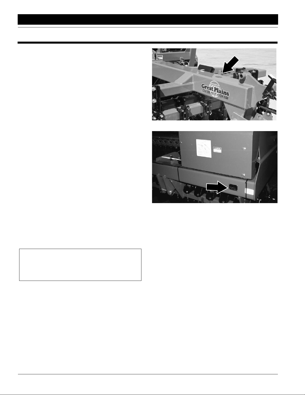
Great Plains Mfg., Inc.
Figure A
Serial Number Plate, Hitch
Using This Manual
This manual will familiarize you with safety, assembly,
operation, adjustments, troubleshooting and maintenance.Readthis manualand followtherecommendations
to help ensure safe and efficient operation.
Theinformation in this manual iscurrent at printing. Some
parts maychange to assure top performance.
Definitions
Right-handand left-hand as used in thismanual are determined by facing the direction the machinewill travel while
in use unless otherwise stated.
IMPORTANT: A crucial point of information related to
the preceding topic. For safe and correct oper ation,
read and follow the directions provided before continuing.
NOTE: Useful information related to the preceding topic.
Owner Assistance
If you need customer service or repair parts, contact a
Great Plains dealer. They have trained personnel, repair
parts and equipment specially designed for Great Plains
products.
Your machine’sparts were specially designed and should
onlybereplaced withGreat Plainsparts.Alwaysuse serial
and model numbers when ordering parts from yourGreat
Plainsdealer.The serial-number plates arelocated on the
implement as shown in Figure A and Figure B.
Figure B
Serial Number Plate, Drill
Recordyourimplement modeland serialnumbers herefor
quick reference:
Model Number: _________________________________
Serial Numbers: _________________________________
Your Great Plains dealer wants youto be satisfied with
your new machine. If you do not understand any part of
this manual or are not satisfied with the service received,
please take the following actions.
1. Discuss the matter with your dealershipservice manager.Make sure they are aware of anyproblems so
they can assist you.
2. If you are still not satisfied, seek out theowner or general manager of the dealership.
3. For further assistance write to:
Product Support
Great Plains Mfg. Inc., Service Department
PO Box 5060
Salina, KS 67402-5060
USA
FCP1000 Three-Meter Drill and Hitch 148-693M-A 7/5/2005
8
Page 11
Great Plains Mfg., Inc.
Section 1 Preparation and Setup
Section 1 Preparation and Setup
This section will help you prepare your tractor and implement
for use.
Prestart Checklist
1. Read and understand “Important Safety Information,”
page 1.
2. Check that all working parts are moving freely, bolts are
tight, and cotter pins are spread.
3. Check that all grease fittings are in place and lubricated.
Refer to Lubrication,“Maintenance and Lubrication,”
page 33.
4. Check that all safety decals and reflectors are correctlylocated and legible.Replace if damaged. See Safety De-
cals,“Important Safety Information,”
page 4.
5. Inflate tires to pressure recommended and tighten wheel
bolts as specified. See “Appendix,” page 40.
Wiring Drill
NOTE: If tractor does not comply with ASAE connector, use
the European adapter.
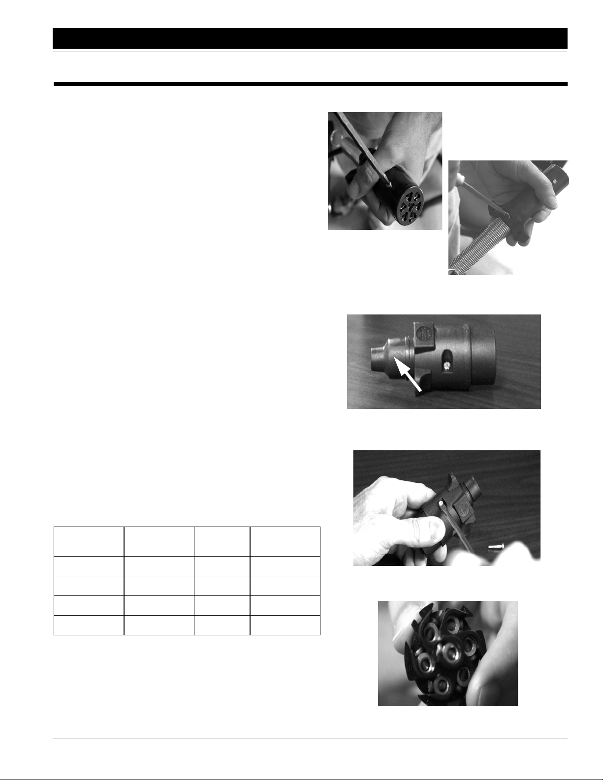
1. Remove screw from outer casing of ASAE connector.
Loosen screw holding wires in place from outer casing of
ASAE connector. Pull outer casing apart. Disconnect
wiresfrom connector by removing screws.See Figure 1-1.
2. Completely remove outer casing from wires.
3. Remove black rubber end piece from European adapter.
Thread wires through blackrubber end piece starting with
the smaller end. See Figure 1-2.
4. Removethetwo screwsholding the outercasing of the European adapter together. Keep for reuse. See Figure 1-3.
5. Removeconnector from outercasing. Thread wires under
metal bar in bottom of outer casing.
6. Attach wires to connector using the terminal number indicators on the back of the connector and the table below.
See Table below and Figure 1-4.
10. Slideblackrubber endpiece overthe endof theouter
casing securing the wires.
23264
23265
Figure 1-1
Removing ASAE Connector
23252
End Piece
Figure 1-2
European Adapter
23254
Conductor
Indicator
Wire
Color
Terminal
Number
Circuit
Wht White 3 Ground
Yel Yellow 1 Left Blinker
Grn Green 4 Right Blinker
Brn Brown 6 Tail Lamps
7. Align connector in bottom of outer casing.
NOTE: BE SURE CONNECTORAND CASING ARE PROP-
ERLY ALIGNED,OTHERWISE CASING WILL NOT FIT CORRECTLY.
8. Tighten screws securing wires and metal bar in place.
9. Replace top of outer casing. Insert and tighten screws removed in Step 3.
7/5/2005
Figure 1-3
Remove Screws to Outer Casing
23255
Figure 1-4
Back of Connector
FCP1000 Three-Meter Drill and Hitch 148-693M-A
9
Page 12
Section 1 Preparation and Setup
Great Plains Mfg., Inc.
Hitching Tractor to Implement
!
DANGER!
You may be severely injured or killed by being crushed between
the tractor and drill. Do not stand or place any part of your
body between drill and moving tractor. Stop tractor engine and
set park brake before installing pins. Refer to Figure 1-1.
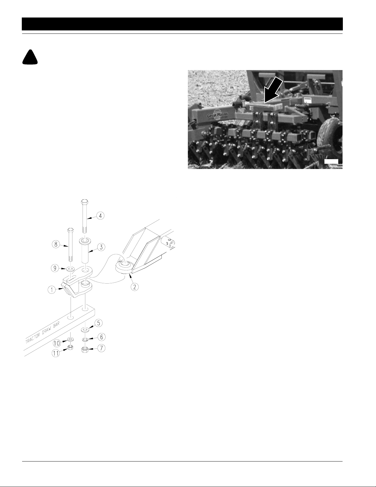
Refer to Figure 1-5.
1. Place hitch weldment (1) over ball swivelon hitch
tongue (2). Hold hitch weldment in place byinserting
spacer tube (3) through hitch clevis and ball swivel.
2. Back tractor up to hitch and bolt hitch weldment to
tractor drawbar using 1-by-10-inch bolt (4), large flat
washer (5), lockwasher (6), and nut (7).
3. Use 3/4-by-9-inch bolt (8) to bolt hitch weldment
through its slotted hole and onto secondary hole of
tractor drawbar. Install a 3/4-inch flat washer (9) next
to top slotted hole and fasten with a lock washer (10)
and nut (11). Tighten both bolts.
4. Securely attach safety chain to tractor-drawbar frame.
5. Remove jack from stob on side of hitch tongue and
place in transport position on implement. See Figure
1-6.
17219
Figure 1-6
Jack in Transport Position
17215
Figure 1-5
Drawbar Assembly Illustration
FCP1000 Three-Meter Drill and Hitch 148-693M-A 7/5/2005
10
Page 13
Great Plains Mfg., Inc.
Section 1 Preparation and Setup
Hydraulic Hook-up
!
WARNING!
Escaping fluid under pressurecan have sufficient force to penetrate the skin. Check all hydraulic lines and hoses before applying pressure. Fluid escaping from a very small hole can be
almost invisible. Use paper or cardboard, not body parts, to
check for suspected leaks. If injured, seek medical assistance
from a doctor that is familiar with this kind of injury. Foreign
fluids in the tissue must be surgically removed within a few
hours or gangrene will result.
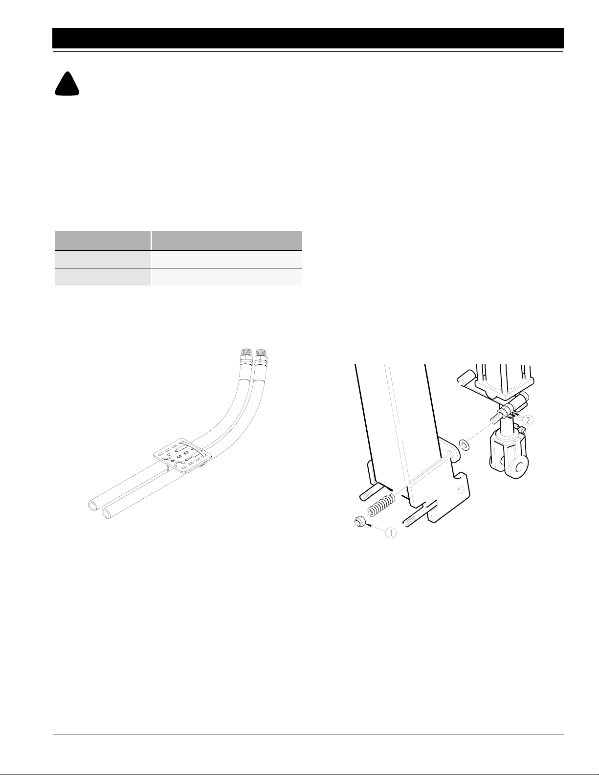
Great Plainshydraulic hoses are colour coded tohelp you
hook-uphoses to your tractoroutlets. Hoses that go tothe
same remote valve are marked with the same colour.
Colour Hydraulic Function
Red T ransport Lift Cylinders
Blue T ongue Cylinder
Todistinguish hoseson the samehydraulic circuit, referto
plastic hose holder. See Figure 1-7. Connect hose under
extended cylinder to outlet you choose for cylinder extension. Connect hose under retracted symbol to outlet for
cylinder retraction.
2. proper level. Add fluid to system as needed. Tongue
cylinder capacity is 1.89 litres (one-half gallon).
3. Raise and safely support hitch, transport frame and
front tongue.
4. Unpin rod end of tongue cylinder. Block, wire or otherwise safely support cylinder so when rod end is fully
extended it does not contact anything.
5. Cycle cylinder completely in and out at least three
times to purge air from cylinder and hoses.
6. Fully extend cylinder and repin rod end.
7. Recheck tractor reservoir and fill to proper level.
Bleeding Transport Lift Cylinders
The transport-lift cylinders are rephasing cylinders and require a special procedure for bleeding air from the circuit.
Read and follow procedure carefully. Cylinders will not
function properly with air in the hydraulic circuit.
1. Check hydraulic fluid in tractor reservoir and fill to
proper level. Add fluid to system as needed. Transport-lift-cylinder capacity is about 7.57 litres (2 gallons).
2. Jack up and support hitch frame.
3. Remove1/2-inch nylocknuts (1) onspring side of cylinder-support brace.Unpin cylinders. Do not alter position of jam nuts (2) on centre of support-brace bolts.
See Figure 1-8.
17641
Figure 1-7
Hydraulic Hose Color Ties
Connect hydraulichoses fromtongue cylinder toone tractor remote valve. Connect hoses from transport-lift cylinders to another tractor remote valve.
Bleeding Hydraulic Systems
For safe and smooth operation, the hydraulic systems
must be free of air.The hydraulicsystems shouldbe bled
during initial implement set-up. If they were not bled, or if
you replace a hydraulic component during the life to the
drill, bleed the hydraulics.
Bleeding Tongue Cylinder
1. Check hydraulic fluid in tractor reservoir and fill to
7/5/2005
17864
Figure 1-8
Unpin Cylinders
4. Turn cylinders to a position where rodends are higher
than base ends. Support cylinders in a safe location.
5. Start tractor and run engine at idle speed. With rod
ends higher than base ends, hydraulicallyextend cylinders.After cylinderrods are fullyextended, continue
to hold control lever for one minutebefore hydraulically retracting cylinders.
6. Repeatstep5 threetimes tocompletely bleedsystem.
If air is still trapped in either cylinder, it will operate in
jerky, erratic motions. Repeat steps until cylinder
movement is smooth and even.
FCP1000 Three-Meter Drill and Hitch 148-693M-A
11
Page 14

Section 1 Preparation and Setup
7. Repin cylinders to hitch frame. Reinstall short compression springs on cylinder-support-brace bolts and
re-tighten 1/2-inch nylocknuts until springs are compressed to 32 mm (1 1/4 inches). If for any reason the
1/2-inch jam nuts in centre of support-brace bolts
were changed, referto Transport Cylinder Support
Brace, page 32, for proper adjustment.
8. Refill tractor hydraulic-fluid reservoir to proper level.
Bleeding Marker Hydraulics
!
CAUTION!
You may be injured if hit by a folding or unfolding marker.
Markersmayfall quickly and unexpectedlyif the hydraulics fail.
Neverallow anyonenear the drill when folding or unfolding the
markers.
1. Check that tractor hydraulic reservoir is full.
2. With both markers lowered into field position, loosen
hydraulic-hosefittings atrod and base endsof marker
cylinders. Loosen fittings on back side of sequence
valve.
Great Plains Mfg., Inc.
IMPORTANT: Never bleed an O-ring fitting. Instead,
bleed a nearby pipe or JIC fitting.
3. Withtractor idling, activatetractor hydraulicvalveuntil
oilseeps out around a loosenedfitting. Tighten that fitting.
IMPORTANT: JIC fittings do not require high torque.
JIC and O-ring fittings do not require sealant. Always
use liquid pipe sealant when adding or replacing pipethread fittings. Toavoid cracking hydraulic fittings from
over tightening, do not use plastic sealant tape.
4. Reactivate tractor hydraulic valve until oil seeps out
around another loosened fitting. Tighten that fitting.
Repeat process until all loosened fittings have been
bled and tightened.
FCP1000 Three-Meter Drill and Hitch 148-693M-A 7/5/2005
12
Page 15

Great Plains Mfg., Inc.
Section 2 Operating Instructions
Section 2 Operating Instructions
This section coversgeneral operation. Experience,
machine familiarity and the following information will lead
to efficient operation and good working habits. Always
operate farm machinery with safetyin mind.
Prestart Checklist
1. Carefully read “Important Safety Information,” beginning on page 1.
2. Lubricate implement as indicated under Lubrication,
“Maintenance and Lubrication,” page 33.
3. Check all tires for proper inflation as indicated on Tire
Inflation Chart,“Appendix,” page 40.
4. Check all bolts,pins and fasteners. Torque as specified on Torque Values Chart,“Appendix,” page 40.
5. Check implement for worn or damaged parts. Repair
or replace beforegoing to the field.
6. Checkhydraulichoses,fittings andcylinders forleaks.
Repair or replace before going to the field.
17129
Figure 2-1
Pivot Lock Tube
Duringnormalfield operation,operate hitchwith pivot-lock
tubes unsecured so hitch can pivot and drill openers can
properly track coulters. Refer to Figure 2-2.
Field Operation
1. Hitchimplement to asuitable tractor.Referto Hitching
Tractorto Implement,“Assemblyand Setup,”page 9.
2. For proper coulter-to-opener tracking, unlock pivotlock tubes. Refer to Pivot Lock Tubes, this page.
3. Hydraulically adjust coulters to desired depth. Note
reference measurement on tongue-cylinder gauge to
help you achieve the same coulter depth with each
field pass. Refer to Coulter Depth,“Adjustments,”
page 16, forfurther adjustment instructions.
4. Set seeding rate. Refer to Setting the Seeding Rate,
“Adjustments,” page 20.
5. Load box with clean seed.
6. Pull forward, lower coulters to desired depth, lower
drill, and begin seeding.
7. Alwayslift drill out of groundwhen turningat row ends
and for other short turns. Seeding will stop automatically as drill is raised.
Opener Operation
Neverback up with openers in ground. If you do, check all
openers to be sure none are clogged or damaged.
For information on seeding depth and opener adjustments, refer to Seeding Depth,“Adjustments,” page 16.
For more information on troubleshooting opener problems, see “Troubleshooting,” page 30.
Pivot Lock Tubes
The pivot-locktubes are behind the stabilizer cylinders on
each side of implement. See Figure 2-1.
11880
Figure 2-2
Pivot Lock Tubes Unsecured–Normal Field Position
When drilling on steep slopes or transporting, secure
pivot-locktubes. To lock tubes,turn tubes so theyare horizontal with hitch frame. Refer to Figure 2-3.
10555
Figure 2-3
Pivot Lock Tubes Secured–Transport Position
Youcan adjust spring tension on pivot-locktubes. Referto
Pivot Lock Tube Adjustment, “Adjustments,” page 20.
7/5/2005
FCP1000 Three-Meter Drill and Hitch 148-693M-A
13
Page 16

Section 2 Operating Instructions
Great Plains Mfg., Inc.
Marker Operation
Optional markers are powered off the same circuit as the
tongue cylinder. After setting coulter depth with tongue
cylinder,turn selectorvalve to the left tooperate markers.
See Figure 2-4.
17466
Figure 2-4
Turn Selector Valve for Marker Operation
Transport Lift Cylinders
The transport-lift cylinders are rephasing hydraulic cylinders. After a period of normal use, the cylinders may get
outof sequence. If this happens,the hitch will lift unevenly
or one set of tires will not retract from the soil.
To rephase cylinders, raise drill completely and hold
hydrauliclever onfora fewseconds toallow cylinderstime
to rephase.
3. Checkthat divider dooris closed soseed and fertilizer
cannot pass between compartments.
4. Check that cleanout door (1) is latched securely as
shown in Figure 2-5. Close all door latches before
loading fertilizer compartment.
1
16377
Figure 2-5
Cleanout Door Latched
5. Fill fertilizer compartment.
Fertilizer Operation
The fertilizer drill is equippedwith a moveable divider that
partitions the drill box between the seed and the fertilizer.
Use only dry, granular fertilizer in the fertilizer compartment.
1. Clean anyseed or debris from fertilizercompartment.
2. Calibratefertilizer-application rate as explainedunder
Fertilizer Rate Calibration,“Adjustments,” page 26.
FCP1000 Three-Meter Drill and Hitch 148-693M-A 7/5/2005
14
Page 17

Great Plains Mfg., Inc.
Section 2 Operating Instructions
Transporting
!
WARNING!
Towing the implement at high speeds or with a vehicle that is
not heavy enough can lead to loss of vehicle control. Loss of vehicle control can lead to serious road accidents, injury and
death. To reduce the hazard:
• Do not exceed 32 kph (20 mph).
• Do not tow an implement that, when fully loaded, weighs
more than 1.5 times the weight of the towing vehicle.
1. Check that implement is securely hitched to a sufficient tractor. Refer to Hitching Tractor to Implement,
“Preparation and Setup,” page 9. Make sure safety
chain is secured to tractor.
2. Unload seed box before transporting if atall possible.
The implement can be transported with a full boxof
grain, but added weight will increase stopping distance and decrease manoeuvrability.
3. Check that tires are properly inflated. Refer to Tire In-
flation Chart,“Appendix,” page 40.
4. Know implement dimensions in transport position.
Choose a route that provides adequate clearance
from all obstructions. Refer to “Specifications and
Capacities,” page 39, for dimensions.
5. Hydraulically lift drill with transport-lift cylinders.
6. Install transport lock pins in vertical axle tubes.
8. Install lock channel over extended tongue-cylinder
rod. See Figure 2-7.
17217
Figure 2-7
Lock Channel Installed
9. Plug light-harness lead into tractor connector. Always
use warning lights when transporting drill.
10. Comply with all laws when travelling on public roads.
Parking
Perform the followingsteps when parking implement.
Refer to Storage,“Maintenance and Lubrication,” page
33, for information on long-term storage preparation.
1. Park implement on a firm, level area. Lower coulters
and drill to ground.
2. Block tires securely to prevent rolling.
3. Release pressure on hydraulic system, then disconnect hydrauliclines. Check that hose ends do not rest
on ground.
4. Movejack from transport position and place it on stob
on side of hitch tongue.
5. Extend jack until all weight is off tractor drawbar. Remove 1-by-10-inch bolt, washerand nut.
6. Disconnect implement light harness.
17208
Figure 2-6
Lock Pin Installed
7. Secure pivot-lock tubes for transport. Position tubes
sothey are horizontal against hitch frame. See Figure
2-3 on page 12.
7/5/2005
FCP1000 Three-Meter Drill and Hitch 148-693M-A
15
Page 18

Section 3 Adjustments
Section 3 Adjustments
Great Plains Mfg., Inc.
Seeding Depth
To set drill seeding depth, you must:
• Set coulter depth with tongue cylinder.
• Set opener depth with T-handles on press wheel.
• If field conditions make itnecessary, increase coulter
down pressure by adding weights.
• If necessary, adjust individual coulters or openers to
seed in tire tracks.
The following is an introduction to how the coulters and
double-disk openers are designed to control seeding
depth.
Coulters
A no-till coulter is mounted on the hitch directly ahead of
each opener on the drill. The coulters cut through heavy
trash and makea groove in the soil for the openers.
Coulter cutting depth is controlled bythe tongue cylinder.
You also can change the depth of individual coulters by
changingcoulter-mounting height.Referto CoulterDepth,
page 16, forinformation on these adjustments.
The amount of coulter down pressure needed to cut a soil
groovevaries with soil conditions. Adding weightor shortening the coulter spring increases coulter down pressure
and cutting force. Refer to Coulter Down Pressure, page
17, for more information on these adjustments.
Openers
Opener double disks widen the coulter groove to make a
seed bed. Mounted on the rear of each opener is a press
wheel. The press wheels control opener seeding depth
and firm the seed into the soil.
To maintain a consistent seeding depth, upward press
wheel movement is restricted byan independently adjustable stop on each opener. Moving this stop changes the
depth at which seed is placed. The mounting height of
openers that run in tiretracks also can be changed.Refer
to Opener Depth, page 18 for information on these adjustments.
The amount of opener down pressure needed to cut and
widen the coulter groove and to firm theseed into the soil
varies with soil conditions. Opener downpressure canbe
adjusted for all openers or individual openers. Refer to
Opener Down Pressure,page 18, for information on how
to make these adjustments.
Coulter Depth
Adjust coulters to run 13 to 25 mm (1/2to 1 inches) below
the drill openers. Coulter depth can be adjusted hydraulically for all coulters or manually for individual coulters.
Hydraulic Control
Make the following adjustment when drilling in level
ground with the seed box half full.
1. Retract tongue cylinder to transfer weight to coulter
toolbar.
2. Set tongue cylinder so coulters are at desired depth.
Notesetting oncylindergauge (seeFigure 3-1)so you
can return to the same depth.
NOTE: Use cylinder gauge only as a reference. Gauge
does not measure actual coulter depth.
17218
Figure 3-1
Cylinder Gauge
3. With coulters and drill lowered to desired seeding
depth, check that hitch frame (1) runs parallel with
ground as shown in Figure 3-2.
21501
Figure 3-2
Levelling Implement
FCP1000 Three-Meter Drill and Hitch 148-693M-A 7/5/2005
16
Page 19

Great Plains Mfg., Inc.
Section 3 Adjustments
4. If the hitch frame is not level, remove or replace spacers (1) from transport-lift-cylinder rods until hitch is
level.See Figure 3-3.
17854
Figure 3-3
Remove or Install Spacers
Coulter Mounting Height
You can change the depth of individual coulters by adjusting coulter-mounting height. If you adjust coulter height,
be sure to rebolt coulters vertically straight and correctly
spaced. To raise or lower individual coulters:
1. Loosenmountingclamps andadjust coultertodesired
height. Do not lower coulter spring bar below top ubolts on coulter clamp.
2. To re-tighten clamps, refer to Figure 3-4. Snughexheadclamp bolts (1)just until u-boltsare tight on each
side of spring bar.
3. Tighten nuts (2) on u-bolts.
4. Finish tightening hex-head clamp bolts.
Coulter Down Pressure
Added Weight
Inhard soil conditionswhere coulter penetrationis limited,
you can add suitcase weights to the weight brackets on
thehitch. Youcan addup to567 kilograms(1,200 pounds)
21613
to the front brackets.Place an equal amount of weighton
the right and left side to balance the weight distribution.
Figure 3-5
Weight Brackets
Coulter Springs
Coulter-spring length is preset at the factory to 254 mm
(10inches), givingcoulters aninitial operatingforce of 181
kg(400 pounds).Thissetting isadequate formany difficult
no-till conditions. For lighter no-till conditions where rocks
or other obstructions are a problem, you can reduce coulter down pressure to give coulters better impact
protection.Referto thefollowing chartforadjusting coulter
down pressure.
10300
Figure 3-4
Individual Coulter Mounting
NOTE:Evenwhen coulter is heldsecurely,theremay be a
gap between clamp halves.
Spring Length Coulter Down Pressure
267 mm (10 1/2 in) 79 kg (175 lbs)
260 mm (10 1/4 in) 136 kg (300 lbs)
254 mm (10 in) 181 kg (400 lbs)
248 mm (9 3/4 in) 238 kg (525 lbs)
NOTE: Do not reset coulter-spring length shorter than
248mm (9 3/4 inches). Shortening springs more than 248
mm (9 3/4 inches) may contribute to premature failure of
parts and warranty will be voided.
7/5/2005
FCP1000 Three-Meter Drill and Hitch 148-693M-A
17
Page 20

Section 3 Adjustments
Great Plains Mfg., Inc.
Opener Depth
When making opener adjustments, keep in mind that
openers will not run any deeper than coulters till the soil.
Press Wheel Adjustment
Changing the height of the press wheels automatically
changes seeding depth. To adjust, lift T-handle and slide
forward or back as shown in Figure 3-1.
• For shallower seeding, slide handle ahead toward im-
plement.
• For deeperseeding, slide handle back away from imple-
ment.
16671
Figure 3-1
Press Wheel Adjustment
Opener Down Pressure
To adjust downpressure on individual openers that run in
tire tracks, change opener-spring length. To increase
down pressure,loosen thejam nut at lower end of opener
spring, then turn flange nut. See Figure 3-3. Each 6 mm
(1/4-inch) turn adds about 6 kg (13 pounds) of pressure.
After adjusting flange nut, tighten jam nut.
16688
Figure 3-3
Individual Spring Adjustment
IMPORTANT:Do not turnflange nut more than 25 mm
(one inch). Turning flange nut more than 25 mm (one
inch) could cause opener damage.
Opener Mounting Height
Youalso can lowerindividual opener bodies thatrunin tire
tracks. To lower an opener, move opener-pivot bolt to
lower hole in opener mount. See Figure 3-2.
16672
Figure 3-2
Individual Opener Height Adjustment
Disk Scraper Adjustment
To keepopener disks turning freely, dirt scrapers are
mounted between disks to clean as the disks rotate. As
field conditionsvary, you mayneed to adjust the scrapers.
To adjust, loosen 3/8-inch bolt shown in Figure 3-4 and
raise or lowerscraper as needed.
16634
Figure 3-4
Disk Scraper
FCP1000 Three-Meter Drill and Hitch 148-693M-A 7/5/2005
18
Page 21

Great Plains Mfg., Inc.
Section 3 Adjustments
Harrow Adjustment
Figure 3-5 shows a successful harrow position for no-till
conditions. Because of differentsoil moisture, trash levels
and trash types, you may need to reposition the tube
frame or tines. Initially position the frame and tines as
shown in Figure 3-5, then readjust as necessary.
12667
Figure 3-5
Tine Angle For No-Till Drilling
To adjust the frame, refer to Figure 3-6. Loosen the four
hexnuts (1)on the u-bolts androtate the frame tube(2) as
necessary.
To adjust the tines, refer to Figure 3-6. Loosen the four
1/2-inchhex nuts(3) on the 1/2-inchu-bolts (4) on the support bar (5). Rotate tine tubes (6) so the tines (7) are
against the stop bushings (8) and are angled back as necessary. Re-tighten hexnuts on u-bolts.
16297
Leaf Spring Adjustment
Aleaf spring islocated just aheadof the verticalpivot. See
Figure 3-7. The spring is designed to provide just enough
forceto keepthe hitchsquare andstable forturning atfield
ends and to add stability for drilling in rough field conditions. Proper leaf-spring adjustment is important for
smooth implement operation.
Toadjust properly, referto Figure 3-7.Square tongue with
transport frame and adjust 3/8-inch u-bolts (1) on each
side until leaf-spring rollers (2) just make contact with
roller pads (3) on transport frame. Make sure both right
and left sides are adjusted properly.
17133
Figure 3-7
Leaf Spring Adjustment
Marker Adjustments
Folding Speed
Adjust folding speed with hex adjustment screws on the
sequence-valvebody. See Figure3-8. There isone adjustment screw for raising speed (1) and one for lowering
speed (2). Identify adjustment screws by markings
stamped in valve body.
With tractor idling at a normal operating speed, adjust
marker folding to a safe speed.Turn adjustment screws
clockwise to decrease folding speed and counterclockwise to increase folding speed. Excessivefolding speed
could damage markers and void the warranty.
After adjusting the folding speed, tighten jam nuts on hex
adjustment screws to hold settings.
7/5/2005
Figure 3-6
Harrow Adjustment
14048
Figure 3-8
Speed Adjustment, Sequence Valve
FCP1000 Three-Meter Drill and Hitch 148-693M-A
19
Page 22

Section 3 Adjustments
Great Plains Mfg., Inc.
Disk Adjustments
Refer to Figure 3-9.
If mark left bymarker diskis noteasy to see, change disk
angleto make awider mark. Loosen two 1/2-inchcarriage
bolts (1) holding disk mount. Rotate disk mount as
desired.
If the marker disk is not square with the ground when the
markeris loweredin thefield, or ifmarkerarm tends tofold
up while lowered in the field, change disk angle relative to
ground. Loosen 1/2-inch bolts (2) and rotate marker
mount until marker disk is square with ground.
To adjustwhere the disk marks,loosen u-bolt (3) andslide
marker-mount tube in or out as necessary. Re-tighten ubolt.
Seed-Lok Lock Up
Optional Seed-Lok firming wheels provide additional
seed-to-soilcontact. The wheelsare spring loadedand do
not require adjusting. In some wet and stickyconditions
the wheels mayaccumulate soil.
To lockup firming wheels, hook one end of chain in the
opener-body hole just above the wheel arm (1). Pull firming-wheel arm (2) up as high as possible and wrap chain
around arm. Hook other end of chain in a link. Leave no
slack in chain; secure wheel arm in its highest position.
1
2
16856
15667
Figure 3-9
Disk Angle
Pivot Loc k Tube Adjustment
To adjust tension on pivot-lock tubes, loosen jam (1) nut
and screw bolt (2) in or out to desired setting and re-tightening jam nut. When pivot frameis 90 degreesto tongue,
bolt head should be about 2 mm (1/16 inch) away from
stop on pivot frame (3).
Figure 3-11
Seed-Lok Lock Up
Setting the Seeding Rate
Calibrating the seeding rate requires four steps:
• set correct drive type,
• setting seed-rate handle,
• positioning seed-cup doors, and
• checking seeding rate.
Refer to the seed-rate charts starting on page 23. These
charts list proper sprocketsizesand seed-rate-handle settings for various seeds and seeding rates.
The seed-rate charts are based on cleaned, untreated
seed of average size and test weight. The charts are
based on 13.0/55-16 12 PR AWtires. Many factors will
affect seeding rates including foreignmaterial, seed treatment, seed size,field conditions, tire pressure and test
weight. You likely will need to make minor adjustments.
Set and check the seeding rate using procedures below,
then readjust rate as necessary.
17855
Figure 3-10
Adjust Tension on Pivot-Lock Tube
FCP1000 Three-Meter Drill and Hitch 148-693M-A 7/5/2005
20
Page 23

Great Plains Mfg., Inc.
Section 3 Adjustments
Changing Drive Sprockets
Forcorrect drive type,refer to seed-ratecharts starting on
page 23. The charts lists drive types as 1, 2, 3 or4. Refer
to the following table for correct-sized sprocket for each
drive type.
DriveType Sprocket Speed
Type 1 72-tooth Slowest
Type 2 34 tooth Two Times FasterThan Type 1
Type 3 23-tooth Three Times FasterThan Type 1
Type 4 14-tooth Five Times Faster Than Type 1
To changedrivetypes, removethechain guard (1) byloosening wing nuts (2). See Figure 3-12.
2
2
1
21502
Figure 3-12
Chain Guard
Setting Seed-Rate Handle
Positionseed-rate handle shownin Figure 3-14 to setting
indicated on seed-rate charts.
To adjust,loosen wing nutunder handle.Slide handle until
indicator is just past the correct setting, then move the
handle back until indicator lines up with correct setting.
16653
Figure 3-14
Seed-Rate Handle
Positioning Seed-Cup Doors
For wheat and other small seeds, move seed-cup-door
handles to the highest position. For soybeans and other
large seeds, lowerhandles to second position. If excessiveseed cracking occurs, lower handles to third position.
For seed-cup clean out, move handles tothe fourth, wideopen position.Make sure all handles are in the same position before drilling.
Loosen idler (1) and remove drivechain shown in Figure
3-13. Remove lynch pin from shaft (2) and re-arrange
sprockets on shaft.
1
2
17211
Figure 3-13
Drive Sprockets
NOTE:Be sure chain isinstalled with the chainconnector
link retainer towardsthe centerline and the clip opening
(split end) facesthe opposite way of the chain travel.
16651
Figure 3-15
Seed-Cup-Door Handle
7/5/2005
FCP1000 Three-Meter Drill and Hitch 148-693M-A
21
Page 24

Section 3 Adjustments
Checking Seeding Rate
!
WARNING!
You may be severely injured or killed by being crushed by the
falling implement. Always have transport locks in place and
frame sufficiently blocked up when working on the implement.
1. Raisedrillwith tractor hydraulicsso gaugewheels are
off ground.Rotate drive(farright) gauge wheel to see
that metering system is working properly and free
from foreign material.
2. Check that implement tires are 13.0/55-1612 PR AW
and properly inflated. Refer to Tire Inflation Chart,
“Appendix,” page 40.
3. Record weight of an empty containerlarge enoughto
hold seed metered for one hectare (acre).
4. Place several kilos (pounds) of seed overthree seed
cups on an outside end of the seed box. Pull seed
tubes off of these three openers.
5. Turn crank on contact-wheel shaft on right-hand side
of drill several times to fill seed cups. Turn crank until
seed drops to ground from each seed cup.
6. Place a container under these three tubes to gather
metered seed.
7. Turn crank on contact-wheel shaft clockwise 32 revolutionsfor 1/100 hectare seeding rate(13 rotations for
a 1/100 acre seeding rate). While turning, checkthat
the seed cups haveplenty of seed coming into them.
NOTE: If implement is not equipped with a calibration
crank, turn drive gauge wheel 319 rotations for a one-hectare seeding rate or 127 rotation for a one-acre seeding
rate.
8. Weighmeteredseed.Subtract initialcontainerweight.
Multiply weight by
• 633.33 for 158 mm (6.2 inch) row spacing or
to determine total kilogramsper hectare (pounds per
acre) seeded. If this figure is different than desired,
adjust seed-rate handle accordingly.
NOTE:You maywantto repeat thecalibration procedure if
your results vary greatly from the seed-rate chart.
9. When drilling, check seeding rate by noting acres
drilled, amount ofseed added to drill and seed levelin
seed box. If you are seeding more or less than desired, adjust rate slightly to compensate for field conditions.
Great Plains Mfg., Inc.
FCP1000 Three-Meter Drill and Hitch 148-693M-A 7/5/2005
22
Page 25

Great Plains Mfg., Inc.
Section 3 Adjustments
Seed Rate Charts
White Rows, Metric
Shaded Rows, English Units
Seed-Rate Handle
Space
Alfalfaor
Rape
Drive Type 1
(Based on 60#/bushel; .772 kb/har)
Barley
Drive Type 1
(Based on 51#/bushel; .656 kb/har)
Barley
Drive Type 2
6.2 in.
157.9mm
6.2 in.
157.9mm
6.2 in.
157.9mm
0 5 10 15 20 25 30 35 40 45 50 55 60 65 70 75 80 85 90 95 100
Row
2.2 5.5 8.3 12.0 15.4 19.1 22.80 27.2 31.5 36.7 41.0 44.8 49.6 54.2 59.0 63.2 68.7 73.9 79.30 81.6 84.0
2.6 6.4 9.6 13.9 17.9 22.2 26.5 31.6 36.6 42.6 47.6 52.0 57.6 63.0 68.5 73.4 79.8 85.8 92.1 94.8 97.6
1.9 4.5 7.6 10.7 14.4 18.1 22.2 26.1 30.1 34.5 38.9 43.3 47.8 52.8 57.1 61.7 65.5 69.1 72.6 73.1 73.7
2.2 5.2 8.8 12.4 16.7 21.0 25.8 30.3 35.0 40.1 45.2 50.3 55.5 61.3 66.3 71.7 76.1 80.3 84.3 84.9 85.6
3.5 8.7 15.9 21.6 29.8 37.0 45.1 53.7 61.8 71.0 76.4 87.0 95.8 104.1 113.5 122.7 132.8 142.4 151.6 154.0 156.4
4.1 10.1 18.5 25.1 34.6 43.0 52.4 62.4 71.8 82.5 88.8 101.1 111.3 120.9 131.9 142.5 154.3 165.4 176.1 178.9 181.7
Seeding Rate, Pounds per Acre/Kilograms Per Hectare
(Based on 51#/bushel; .656 kb/har)
6.2 in.
8.5 21.2 38.8 52.7 72.9 90.4 110.3 131.3 151.1 173.7 194.1 212.7 234.4 254.6 277.7 300.0 324.7 348.3 370.6 376.5 382.4
Barley
Drive Type 3
(Based on 51#/bushel; .656 kb/har)
Buck-
157.9mm
6.2 in.
157.9mm
9.9 24.6 45.1 61.2 84.7 105.0 128.1 152.5 175.5 201.8 225.5 247.1 272.3 295.8 322.6 348.5 377.2 404.6 430.5 437.4 444.2
0.0 11.3 21.0 29.4 41.9 52.2 65.0 77.9 92.4 108.8 123.1 135.7 150.4 165.4 179.5 195.4 209.3 224.0 252.6 241.9 244.5
0.0 13.1 24.4 34.2 48.7 60.6 75.5 90.5 107.3 126.4 143.0 157.6 174.7 192.1 208.5 227.0 243.1 260.2 293.4 281.0 284.0
wheat
Drive Type 4
(Based on 48#/bushel; .618 kb/har)
6.2 in.
0.0 3.7 8.2 11.7 16.1 20.1 24.1 28.3 32.8 37.0 41.8 45.7 49.9 54.4 59.1 64.7 69.80 75.7 81.9 83.2 84.9
Flax or
157.9mm
0.0 4.3 9.5 13.6 18.7 23.4 28.0 32.9 38.1 43.0 48.6 53.1 58.0 63.2 68.7 75.2 81.1 87.9 95.1 96.7 98.6
Sudan
Drive Type 1
(Based on 55#/bushel; .708 kb/har)
6.2 in.
1.4 4.7 8.2 11.7 15.7 19.5 23.4 27.2 31.5 35.7 39.8 44.0 48.5 52.4 57.0 61.7 66.00 70.8 75.8 77.0 78.1
Millet
Drive Type 1
(Based on 60#/bushel; .722 kb/har)
157.9mm
1.6 5.5 9.5 13.6 18.2 22.7 27.2 31.6 36.6 41.5 46.2 51.1 56.3 60.9 66.2 71.7 76.7 82.2 88.1 89.5 90.7
6.2 in.
0.0 4.7 8.8 13.0 17.7 22.5 27.80 33.5 39.0 44.8 51.5 56.7 62.8 68.8 74.7 80.8 86.6 91.7 97.70 100.3 102.1
Milo
Drive Type 1
(Based on 64#/bushel; .824 kb/har)
157.9mm
0.0 5.5 10.2 15.1 20.6 26.1 32.3 38.9 45.3 52.0 59.8 65.9 73.0 79.9 86.8 93.9 100.6 106.5 113.5 116.5 118.6
7/5/2005
FCP1000 Three-Meter Drill and Hitch 148-693M-A
23
Page 26

Section 3 Adjustments
White Rows, Metric
Shaded Rows, English Units
Great Plains Mfg., Inc.
Seed-Rate Handle
Space
6.2 in.
Oats
Drive Type 3
(Based on 37#/bushel; .476 kb/har)
Peas
Drive Type 3
(Based on 61#/bushel; .785 kb/har)
Pinto
Beans
Drive Type 1
(Based on 61#/bushel; .785 kb/har)
Rice-
Long Grain
Drive Type 3
157.9mm
6.2 in.
157.9mm
6.2 in.
157.9mm
6.2 in.
157.9mm
0 5 10 15 20 25 30 35 40 45 50 55 60 65 70 75 80 85 90 95 100
Row
0.0 5.2 12.1 17.3 24.0 31.5 38.7 46.8 54.8 63.2 72.2 79.7 88.0 96.1 104.5 112.2 121.2 129.6 138.6 140.3 139.7
0.0 6.0 14.1 20.1 27.9 36.6 45.0 54.4 63.7 73.4 83.9 92.6 102.2 111.6 121.4 130.3 140.8 150.6 161.0 163.0 162.3
0.0 9.5 18.9 34.1 51.9 68.7 83.9 101.9 118.9 137.4 154.3 169.4 186.2 201.5 218.2 235.4 250.8 266.1 281.4 282.9 284.1
0.0 11.0 22.0 39.6 60.3 79.8 97.5 118.4 138.1 159.6 179.3 196.8 216.3 234.1 253.5 273.5 291.4 309.1 326.9 328.6 330.0
0.0 0.0 8.5 12.9 17.4 23.6 29.60 35.3 41.2 47.1 53.0 58.2 63.7 68.8 74.4 80.8 85.4 90.7 96.60 96.4 96.3
0.0 0.0 9.9 15.0 20.2 27.4 34.4 41.0 47.9 54.7 61.6 67.6 74.0 79.9 86.4 93.9 99.2 105.4 112.2 112.0 111.9
0.0 0.0 13.2 21.6 31.6 41.9 52.7 61.2 70.7 80.8 89.8 98.1 106.5 115.5 125.3 134.7 144.3 153.3 161.0 167.1 172.9
0.0 0.0 15.3 25.1 36.7 48.7 61.2 71.1 82.1 93.9 104.3 114.0 123.7 134.2 145.6 156.5 167.6 178.1 187.0 194.1 200.9
Seeding Rate, Pounds per Acre/Kilograms Per Hectare
(Based on 47#/bushel; .605 kb/har)
6.2 in.
0.0 0.0 21.5 35.3 51.5 68.2 85.9 99.8 115.3 131.8 146.3 160.0 173.7 188.3 204.3 219.6 235.3 249.9 262.5 272.5 281.9
Rice-
Long Grain
Drive Type 4
(Based on 47#/bushel; .605 kb/har)
Rice-
Short Grain
Drive Type 3
(Based on 43#/bushel; .553 kb/har)
Rice-
Short Grain
Drive Type 4
(Based on 43#/bushel; .553 kb/har)
Drive Type1
(Based on 57#/bushel; .553 kb/har)
Rye
157.9mm
6.2 in.
157.9mm
6.2 in.
157.9mm
6.2 in.
157.9mm
0.0 0.0 25.0 41.0 59.8 79.2 99.8 115.9 133.9 153.1 170.0 185.9 201.8 218.7 237.3 255.1 273.3 290.3 304.9 316.6 327.5
2.9 11.0 18.0 28.3 38.3 45.6 55.5 63.5 73.3 83.7 95.6 106.8 117.2 127.9 138.6 147.9 156.5 165.1 174.1 174.1 174.1
3.4 12.8 20.9 32.9 44.5 53.0 64.5 73.8 85.2 97.2 111.1 124.1 136.2 148.6 161.0 171.8 181.8 191.8 202.3 202.3 202.3
4.7 17.9 29.4 46.1 62.5 74.4 90.5 103.5 119.5 136.5 155.9 174.1 191.1 208.5 225.9 241.2 255.1 269.2 283.9 283.8 283.9
5.5 20.8 34.2 53.6 72.6 86.4 105.1 120.2 138.8 158.6 181.1 202.3 222.0 242.2 262.4 280.2 296.4 312.7 329.8 329.7 329.8
0.0 2.8 7.8 12.6 18.5 24.0 28.0 34.6 40.7 47.0 52.0 58.0 62.9 68.3 73.8 80.5 86.50 93.5 101.0 101.7 102.1
0.0 3.3 9.1 14.6 21.5 27.9 32.5 40.2 47.3 54.6 60.4 67.4 73.1 79.3 85.7 93.5 100.5 108.6 117.3 118.1 118.6
FCP1000 Three-Meter Drill and Hitch 148-693M-A 7/5/2005
24
Page 27

Great Plains Mfg., Inc.
Section 3 Adjustments
White Rows, Metric
Shaded Rows, English Units
Seed-Rate Handle
Space
Soy-
beans
Drive Type 2
(Based on 58#/bushel; .747 kb/har)
Soy-
6.2 in.
157.9mm
6.2 in.
157.9mm
0 5 10 15 20 25 30 35 40 45 50 55 60 65 70 75 80 85 90 95 100
Row
0.0 5.8 16.0 26.9 39.6 47.5 58.9 69.3 80.4 91.8 101.6 113.9 125.3 136.1 146.8 158.2 167.4 178.6 190.1 191.1 191.7
0.0 6.7 18.6 31.2 46.0 55.2 68.4 80.5 93.4 106.6 118.0 132.3 145.6 158.1 170.5 183.8 194.5 207.5 220.8 222.0 222.7
0.0 11.5 22.5 40.4 59.5 70.7 88.9 101.0 116.3 131.3 148.1 164.0 180.7 196.3 213.6 227.5 248.2 265.3 284.0 283.8 284.3
0.0 6.7 18.6 31.2 46.0 55.2 68.4 80.5 93.4 106.6 118.0 132.3 145.6 158.1 170.5 183.8 194.5 207.5 220.8 222.0 222.7
beans
Drive Type 3
(Based on 58#/bushel; .747 kb/har)
6.2 in.
0.0 19.0 37.0 66.0 97.0 115.0 145.0 165.0 190.0 214.0 241.0 267.0 295.0 320.0 348.0 371.0 405.0 433.0 463.0 463.0 464.0
Soy-
157.9mm
0.0 22.1 43.0 76.7 112.7 133.6 168.4 191.7 220.7 248.6 280.0 310.2 342.7 371.7 404.3 431.0 470.5 503.0 537.9 537.9 539.0
beans
Drive Type 4
(Based on 58#/bushel; .747 kb/har)
6.2 in.
0.0 0.0 2.0 4.2 6.1 8.3 10.7 12.9 15.4 17.8 20.2 22.5 24.9 27.3 29.7 39.1 34.10 36.0 38.8 39.4 40.7
Sunflow-
157.9mm
0.0 0.0 2.3 4.9 7.1 9.6 12.4 15.0 17.9 20.7 23.5 26.1 28.9 31.7 34.5 45.4 39.6 41.8 45.1 45.8 47.3
ers
Drive Type 1
(Based on 28#/bushel; .360 kb/har)
Seeding Rate, Pounds per Acre/Kilograms Per Hectare
6.2 in.
Wheat
Drive Type 2
(Based on 64#/bushel; .824 kb/har)
157.9mm
Wheat
Drive Type 3
(Based on 64#/bushel; .824 kb/har)
157.9mm
Wheat
Grass
Drive Type 1
(Based on 23#/bushel; .296 kb/har)
157.9mm
0.0 12.5 21.9 30.4 39.5 49.7 57.4 69.9 80.4 91.4 104.7 115.1 127.4 140.3 152.2 164.2 177.1 189.9 203.0 205.7 205.9
0.0 14.5 25.4 35.3 45.9 57.7 66.7 81.2 93.4 106.2 121.6 133.7 148.0 163.0 176.8 190.8 205.7 220.6 235.8 239.0 239.2
6.2 in.
0.0 15.9 30.6 44.7 59.5 74.2 87.5 103.6 120.1 136.5 153.3 168.0 185.6 202.4 220.2 239.9 255.8 273.6 289.8 296.7 298.8
0.0 18.5 35.5 51.9 69.1 86.2 101.6 120.4 139.5 158.6 178.1 195.2 215.6 235.1 255.8 278.7 297.2 317.8 336.7 344.7 347.1
6.2 in.
0.0 0.9 2.1 3.0 4.2 5.1 6.0 7.4 8.4 9.6 10.8 11.9 13.1 14.2 15.4 16.8 17.9 19.3 18.50 20.8 21.1
0.0 1.0 2.4 3.5 4.9 5.9 7.0 8.6 9.8 11.2 12.5 13.8 15.2 16.5 17.9 19.5 20.8 22.4 21.5 24.2 24.5
7/5/2005
FCP1000 Three-Meter Drill and Hitch 148-693M-A
25
Page 28

Section 3 Adjustments
Fertilizer Rate Calibration
The fertilizer rates are controlled by a sprocket speed
change selection and by a slide gate which controls the
meter opening size.The charts shownare calculated with
the openings at 100% open. Anyadjustments to the opening at less than 100% open will have to be calibrated for
the correct rate. (See calibration instructions below.)
Fertilizerapplication rates will vary with fertilizertype, density and particle size. Relativehumidity and field conditions canalso affect application rates.The charts on page
27 are based on fertilizer with average particle size and a
density of 1.04 kilograms per litre (65 pounds per cubic
foot). Initially set rate according to charts, then calibrate
drill to your material as described on this page.
1. Refer to fertilizer rate charts on page 27 forcorrect
sprocket sizes for your drill and desired meter rate.
IMPORTANT:The rate charts are for granularfertilizer
with a density of 1.04 kilograms per litre (65 pounds
per cubic foot). If you are applying fertilizer with a different density, use density conversion chart on page
28.
2. To switch between high and low range,loosen and
slide idler sprocket (1) out of chain shown in Figure 3-
1. Remove lynch pin from end of shaft and install correct sprocket.
•Forhigh range, install 16-tooth sprocket and shorten
chain by removing 16-pitch strand.
•Forlow range, install44-tooth sprocket andlengthen
chain by reinstalling 16-pitch strand.
•For extra-high range, install 12-tooth sprocket and
shorten chain by removing 16-pitch strand.
•For special high range, install12-tooth sprocketand
shorten chain by removing 16-pitch strand.
NOTE: Special High Range Fertilizer Sprocket
In order to run special high rate fertilizer it will be necessary to change the final drivesprocket from a 12tooth to a
19 tooth sprocket.Refer to Figure 3-2.
a. Loosen the idler sprocket on the fertilizer final
drive chain.
b. Remove the lynch pin and remove the 12 tooth
sprocket.
c. Install the 19 tooth sprocketand replace thelynch
pin.
d. Tighten the idler sprocket on the fertilizer final
drive chain
Moveidler sprocketbackinto placeso chainhas 6mm
(1/4-inch) slack.
12/16/44T
1
16379
Figure 3-1
Hi/Low Range Sprocket
Great Plains Mfg., Inc.
19T
21896
Figure 3-2
Special High Range Sprocket .
3. To change driver/driven ratio, refer to Figure 3-3..
Loosenand slideidler sprocketsout ofchain. Remove
lynch pins from shafts. Place correct sprockets on
shafts. Store sprockets not used on ends of shafts.
Reinstall chain and slide idlers back into place so
chain has 6 mm (1/4-inch) slack.
Driven
iver
Dr
16378
Figure 3-3
Driver/Driven Sprockets
4. Raise drill with tractor hydraulics so the contact
wheels are not touching the gauge wheels. Rotate
drive gauge wheel to see that metering system is
working properly and free from foreign material.
5. Check that your gauge-wheel tires are 13.0/55-16 12
PR AW and properly inflated. Refer to Tire Inflation
Chart,“Appendix,”page 40.
6. Place severalkilos (pounds) of fertilizer over three fertilizer feed cups on outside end of drill box. Pull fertilizer tubes off of these three disk openers.
7. Weigh an empty container large enough to hold fertilizer applied to one hectare (acre).
8. Turn drive wheeluntil fertilizer starts to drop toground.
9. Place container under the three tubes to gather metered fertilizer.
10. Turndrivegauge wheel319rotations foraone-hectare
seeding rate or 127 rotations for a one-acre seeding
rate. Check that feedcups have plenty of fertilizer coming into them.
FCP1000 Three-Meter Drill and Hitch 148-693M-A 7/5/2005
26
Page 29

Great Plains Mfg., Inc.
Section 3 Adjustments
11. Weighmetered material. Subtractweight of empty container. Divide by three. Multiply by number
of openers on your drill to determine total kilograms (pounds) metered per hectare (acre). If
this figure is different than desired, reset sprockets accordingly.
NOTE:You maywant to repeat calibration procedure
if your results vary greatly from fertilizer rate chart.
12. When drilling, check metering rate bynoting hectares(acres) drilled, amount of fertilizer added to
drill and levelof material in drill box.If you are applying more or less fertilizer than desired, adjust
meteringrate slightly tocompensate forfield conditions.
Fertilizer Meter Rate Charts
Based on 1.04 kilograms-per-litre (65 pounds-per-cubic-foot) density
For 157.9 mm (6. 2 in.) Row Spacing
Metering
Rate
kg/har lb/acre Range Driver Driven kg/har lb/acre Range Driver Driven
48.8 42 Low 12T 21T 141.7 122 High 12T 20T
51.1 44 Low 12T 20T 142.9 123 Low 20T 12T
54.6 47 Low 12T 19T 148.7 128 High 12T 19T
56.9 49 Low 12T 18T 151.0 130 Low 21T 12T
60.4 52 Low 12T 17T 156.8 135 High 12T 18T
63.9 55 Low 12T 16T 166.1 143 High 12T 17T
69.7 60 Low 17T 21T 190.5 164 High 17T 21T
73.2 63 Low 17T 20T 199.8 172 High 17T 20T
76.7 66 Low 17T 19T 210.3 181 High 17T 19T
81.3 70 Low 20T 21T 224.2 193 High 20T 21T
90.6 78 Low 21T 20T 247.4 213 High 21T 20T
95.3 82 Low 21T 19T 260.2 224 High 21T 19T
99.9 86 Low 21T 18T 274.2 236 High 21T 18T
105.7 91 Low 21T 17T 290.4 250 High 21T 17T
112.7 97 Low 21T 16T 333.4 287 High 17T 12T
122.0 105 Low 17T 12T 352.0 303 High 18T 12T
128.9 111 Low 18T 12T 371.7 320 High 19T 12T
134.8 116 High 12T 21T 391.5 337 High 20T 12T
135.9 117 Low 19T 12T 410.1 353 High 21T 12T
Sprockets Metering
Rate
Sprockets
7/5/2005
FCP1000 Three-Meter Drill and Hitch 148-693M-A
27
Page 30

Section 3 Adjustments
Great Plains Mfg., Inc.
For 157.9 mm (6. 2 in.) Row Spacing (Special Range)
Metering Rate Sprockets
kg/har lb/acre Special
173.2 155 12:12 12T 21T
182.2 163 12:12 12T 20T
191.1 171 12:12 12T 19T
201.6 180 12:12 12T 18T
213.6 191 12:12 12T 17T
244.9 219 12:12 17T 21T
256.9 229 12:12 17T 20T
270.3 241 12:12 17T 19T
288.2 257 12:12 20T 21T
318.1 284 12:12 21T 20T
334.5 299 12:12 21T 19T
352.4 315 12:12 21T 18T
373.3 333 12:12 21T 17T
428.6 383 12:12 17T 12T
452.5 404 12:12 18T 12T
477.9 427 12:12 19T 12T
503.3 449 12:12 20T 12T
527.1 471 12:12 21T 12T
Range
Driver Driven
For 157.9 mm (6. 2 in.) Row Spacing (Special High Range)
Metering Rate Sprockets
kg/har lb/acre Special
274.3 245 12:12 12T 21T
288.5 258 12:12 12T 20T
302.6 270 12:12 12T 19T
319.2 285 12:12 12T 18T
338.1 302 12:12 12T 17T
387.8 346 12:12 17T 21T
406.7 363 12:12 17T 20T
428.0 382 12:12 17T 19T
456.3 407 12:12 20T 21T
503.6 450 12:12 21T 20T
529.6 473 12:12 21T 19T
558.0 498 12:12 21T 18T
591.1 528 12:12 21T 17T
678.6 606 12:12 17T 12T
716.4 640 12:12 18T 12T
756.6 676 12:12 19T 12T
796.8 711 12:12 20T 12T
834.6 745 12:12 21T 12T
Range
Driver Driven
Density Conversion Chart
The fertilizer meter ratecharts are based on fertilizer with a density of 1.04 kilogramsper litre (65 pounds per cubic foot).
If you are applying fertilizer of a different density, use the following table to convert the application rate.
Density, kg/l (lb/ft3) 0.72 (45.0) 0.80 (50.0) 0.88 (55.0) 0.96 (60.0) 1.04 (65.0) 1.12 (70.0) 0.87 (75.0) 0.81 (80.0)
Conversion Factor 1.45 1.30 1.20 1.10 1.00 0.93 0.87 0.81
Example:Your fertilizerhas adensity of 0.72kilogramsper litre,and youwant toapply 100kilograms perhectare. Multiply
desired application rate by the conversion factor.
100 x 1.45 = 145
Adjust drill to setting closest to 145 kilograms per hectare.
FCP1000 Three-Meter Drill and Hitch 148-693M-A 7/5/2005
28
Page 31

Great Plains Mfg., Inc.
Section 3 Adjustments
Small Seeds Attachment
To set and calibratethe seeding rate on the optionalsmallseeds attachment, follow these steps.
1. Set seed-rate handle on small-seeds attachment to
setting indicated on Small Seeds Rate Chart.
2. Calibrate small-seeds attachment to your material by
following the steps under Checking Seeding Rate,
page 22.
Small Seed Rate Charts
Optional Equipment
Seed-Rate-
Handle Setting
Alfalfa,
Crimson Clover
and Red Alsike
Row
Space
6.2 in.
157.9mm
5 10 15 20 25 30 35 40 45 50 55 60 65 70 75 80 85 90 95 100
Seeding Rate, Pounds per Acre/Kilograms Per Hectare
0.0 2.2 3.5 4.8 6.0 7.5 8.7 9.8 11.2 12.5 13.8 15.1 16.4 17.5 18.6 20.2 21.4 22.9 24.0 25.2
0.0 1.8 2.8 3.9 4.8 6.0 7.0 7.9 9.0 10.1 11.1 12.2 13.2 14.1 15.0 16.3 17.2 18.4 19.3 20.3
Annual Rye
Grass, Kentucky
Blue Grass and
Fescue
Bermuda, Red Top,
Unhulled Lespede-
za, Sand, Sercia and
Weeping Love Grass
Hulled Lespede-
za, Red Clover
and Sweet Clover
Orchard Grass
Millet and
Reed Canary
Canary Grass,
Canola, Timothy
and Ladino Clover
6.2 in.
157.9mm
6.2 in.
157.9mm
6.2 in.
157.9mm
6.2 in.
157.9mm
6.2 in.
157.9mm
6.2 in.
157.9mm
0.0 0.2 1.2 1.9 2.7 3.3 4.1 4.6 5.2 5.8 6.3 6.8 7.3 7.8 8.3 8.8 9.2 9.7 10.0 10.5
0.0 0.2 1.4 2.2 3.1 3.8 4.8 5.3 6.0 6.7 7.3 7.9 8.5 9.1 9.6 10.2 10.7 11.3 11.6 12.2
0.0 0.7 1.1 1.7 2.6 3.3 4.1 5.0 5.9 6.6 7.2 7.8 8.4 9.0 9.5 10.2 10.9 11.6 12.2 12.9
0.0 0.8 1.3 2.0 3.0 3.8 4.8 5.8 6.9 7.7 8.4 9.1 9.8 10.5 11.0 11.8 12.7 13.5 14.2 15.0
0.0 1.5 3.4 5.2 7.1 9.0 11.3 13.2 15.3 17.0 19.0 20.8 22.5 24.5 26.4 28.3 30.1 32.1 33.8 35.6
0.0 1.7 3.9 6.0 8.2 10.5 13.1 15.3 17.8 19.7 22.1 24.2 26.1 28.5 30.7 32.9 35.0 37.3 39.3 41.4
0.0 0.0 0.3 0.7 0.9 1.3 1.5 2.0 2.4 2.8 3.3 3.5 3.9 4.4 4.8 5.0 5.5 5.7 6.1 6.3
0.0 0.0 0.3 0.8 1.0 1.5 1.7 2.3 2.8 3.3 3.8 4.1 4.5 5.1 5.6 5.8 6.4 6.6 7.1 7.3
0.4 1.4 2.4 3.5 4.4 5.5 6.5 7.5 8.5 9.5 10.5 11.5 12.5 13.6 14.6 15.6 16.6 17.6 18.5 19.0
0.5 1.6 2.8 4.1 5.1 6.4 7.6 8.7 9.9 11.0 12.2 13.4 14.5 15.8 17.0 18.1 19.3 20.4 21.5 22.1
0.0 1.1 2.1 3.3 4.7 6.1 7.6 9.2 10.7 12.2 13.8 15.5 17.0 18.5 20.3 21.7 23.4 25.4 27.3 29.2
0.0 1.3 2.4 3.8 5.5 7.1 8.8 10.7 12.4 14.2 16.0 18.0 19.7 21.5 23.6 25.2 27.2 29.5 31.7 33.9
Sudan and Bird’s-
Foot Trefoil
7/5/2005
6.2 in.
157.9mm
0.0 1.7 3.3 5.2 6.8 8.7 10.7 12.7 14.7 16.8 19.2 21.2 23.4 25.6 28.0 29.9 32.1 34.2 36.3 38.4
0.0 2.0 3.8 6.0 7.9 10.1 12.4 14.8 17.1 19.5 22.3 24.6 27.2 29.7 32.5 34.7 37.3 39.7 42.2 44.6
FCP1000 Three-Meter Drill and Hitch 148-693M-A
29
Page 32

Section 4 Troubleshooting
Section 4 Troubleshooting
Problem Solution
Great Plains Mfg., Inc.
Drill raising and lowering rough and uneven Check for too little play in slide-block area. Refer to Maintenance, “Maintenance
Coulters not going deep enough Retract tongue cylinder.
Drill not tracking behind coulters Check if coulters are aligned with openers.
Openers plugging in no-till conditions Drill across standing residue.
Drill seeding too deep
Uneven seed spacing or uneven stand
and Lubrication,” page 32.
Check for air trapped in hydraulic lines or cylinders. Bleed hydraulicsif necessary.
Refer to Bleeding the Hydraulic Systems, “Preparation and Setup,” page 11.
Add weight to hitch frame. Refer to Coulter Down Pressure,“Adjustments,” page
17.
Too much weight is being used by openers; set drill openers to lightest spring set-
ting. Refer to Opener Down Pressure, “Adjustments,” page 18.
Shorten coulter springs to increase down pressure. Refer to Coulter Down Pres-
sure, “Adjustments,” page 17.
Check that pivot-lock tubes are in drilling position. Refer to Figure 2-2, page 13.
Check if leaf spring is out of alignment. Refer to Leaf Spring Adjustment, “Adjust-
ments,” page 19.
Change the press-wheel setting. Refer to Opener Depth,“Adjustments,” page 18.
Remove weight from hitch.
Check for plugging in seed cups.
Check if seed tubes are plugged.
Reduce ground speed.
Check that opener disks turn freely.
Use a faster drive type and a lower seed-rate-handle setting. Refer to Setting the
Seeding Rate, “Adjustments,” page 20.
Increase opener down pressure so opener disks penetrate. Referto Opener Down
Pressure, “Adjustments,” page 18.
Check for trash or mud build-up on optional Seed-Lok® wheels.
Opener disks not turning freely
FCP1000 Three-Meter Drill and Hitch 148-693M-A 7/5/2005
30
Check for trash or mud build-up on disk scrapers. Readjust scrapers. Refer to Disk
Scraper Adjustment, “Adjustments,” page 18.
Check if scrapers are too tight, restricting disk movement. Refer to Disk Scraper
Adjustment, “Adjustments,” page 18.
Check disk bearings.
Check opener frame for possible damage.
Check if opener disks turn freely by hand but not in field. If so, reduce down pres-
sure on openers. Refer to Opener Down Pressure, “Adjustments,” page 18.
Check press-wheel adjustment for seeding depth. Refer to Opener Depth,
“Adjustments,” page 18.
Page 33

Great Plains Mfg., Inc.
Section 4 Troubleshooting
Problem Solution
Actual seeding rate
is different than desired
Excessive seed cracking
Hectaremeter (acremeter) does not measure accurately
Uneven seeding depth
Check tire pressure. Proper inflation is listed on Tire Inflation Chart, “Appendix,”
page 40.
Check tire size. Proper size is 13.0/55-16 12 PR AW.
Check for build-up of seed treatment in seed cup. Disassemble cups and scrape
off any build-up.
Check seed-rate setting. Seeding rates will vary with seed weight and size. Refer
to Setting the Seeding Rate, “Adjustments,” page 20.
Use a faster drive type and a lower seed-rate-handle setting.
Position seed-cup handles to a lower notch.
Check tire pressure. Proper inflation is listed on Tire Inflation Chart, “Appendix,”
page 40.
Check tire size. Proper size is 13.0/55-16 12 PR AW.
Check seeding operation for excessive overlap or gaps between passes.
Consider soil conditions–loose soil and slippage will cause variations in acres reg-
istered.
Check to besure hectaremeter (acremeter) is foryour drill. Refer to the parts man-
ual for correct part number.
Hectaremeters and acremeters are accurate within a 5 percent range.
Check that openers have sufficient down pressure. Refer to Opener Down Pres-
sure, “Adjustments,” page 18.
Press wheel not
compacting soil as desired
Press wheels or openers plugging
Seed-cup sprockets locked
up or twisted seed-cup shaft
Chain-Debris/retainer clip
Reset press-wheel depth. Refer to Opener Depth, “Adjustments,” page 18.
Increase down pressure on openers. Refer to Opener Down Pressure, “Adjust-
ments,” page 18.
Consider field conditions. Drilling in damp or wet conditions may increase this
problem.
Reduce down pressure on openers. Refer to Opener Down Pressure, “Adjust-
ments,” page 18.
Do not back up or stop and allow drill to roll back with openers in ground.
Check optional Seed-Lok wheels.
Check for foreign material lodged in seed-cup sprocket.
Look for dried liquid insecticide in seed cups. Remove build-up by disassembling
each cup and scraping turning surfaces.
Be sure retainer clip open end is facing the opposite way of chain travel.
7/5/2005
FCP1000 Three-Meter Drill and Hitch 148-693M-A
31
Page 34

Section 5 Maintenance and Lubrication
Section 5 Maintenance and Lubrication
Great Plains Mfg., Inc.
Maintenance
Properservicing and adjustmentare key tolong life of any
farm implement. With careful and systematic inspection,
you can avoid costly maintenance, time and repair.
Alwaysturn offand remove tractor keybefore making any
adjustments or performing any maintenance.
!
WARNING!
You may be severely injured or killed by being crushed by the
falling implement. Always have transport locks in place and
frame sufficiently blocked up when working on implement.
!
WARNING!
Escaping fluid under pressure can have sufficient pressure to
penetrate the skin. Check all hydraulic lines and fittings before
applying pressure.Fluid escaping from a very small hole can be
almost invisible. Use paper or cardboard, not body parts, and
wear heavy gloves to check for suspected leaks. If injured, seek
medical assistance from a doctor that is familiar with this type
of injury. Foreign fluids in the tissue must be surgicallyremoved
within a few hours or gangrene will result.
1. After using implement for several hours, check all
bolts to be sure they are tight.
2. Inflate tires as specified on Tire Inflation Chart,“Ap-
pendix,” page 40.
3. Replaceany worn,damaged or illegiblesafetydecals.
Obtain new decals from yourGreat Plains dealer.Refer to SafetyDecals,“ImportantSafety Information,”
page 4 fordecal placement.
4. Check drill drive chains for wear. Replace if necessary. Adjust idlers to remove excess slack from
chains.
5. Keepfront slideblocks (1)on transportaxles adjusted
towithin 0.381 to 0.635mm (0.015 to 0.025inch) of inner-axle tubes (2). See Figure 5-1.
Fertilizer Clean Out
After using fertilizer in the FCP1000F, clean drill box as
soon as possible.
1. With a small scoop or can, remove as much fertilizer
as possible from drill box.
2. Unlatch clean-out doors as shownin Figure 5-2. Be
prepared to collect fertilizer that spills from drill box.
3. Wash inside of drill box with water under high pressure. To aid clean out, lift vinyl washout cover and
spray into fertilizer tray. See Figure 5-3
16376
Figure 5-2
Fertilizer Clean-Out Door Unlatched
1
16382
Figure 5-3
2
17860
Figure 5-1
Slide Block Adjustment
FCP1000 Three-Meter Drill and Hitch 148-693M-A 7/5/2005
32
Transport Cylinder Support Brace
The transport-lift cylinders are equipped with support
braces to prevent cylinder buckling during transport.
Thesesupportbraces must beproperly assembledto support transport-lift cylinderswithout bindingor placing undo
side loads on cylinders.
Fertilizer Tray Wash-Out
Page 35

Great Plains Mfg., Inc.
Section 5 Maintenance and Lubrication
Ifcylindersare removedor inner-axle-slideblocksbecome
worn, assemble or adjust support braces as follows.Use
this procedure for both support bolts on the transport-lift
cylinders. See Figure 5-4.
1. Assemble 1/2-by-5 1/2-inch, full-thread bolt (1) to cylinder support brace (2), bolted to rod end cylinder
casting.
2. Screwon three 1/2-inch jam nuts (3)and one 1/2-inch
washer (4) as shown. Tighten first jam nut against cylinder support(2) and run other two jam nuts on nearly
all the way.
3. Install cylinder with support bolts (1) extending
through bracket (5) on outer slide tube and pin both
base end and rod end.
4. Screwouter 1/2-inch jamnut out until 1/2-inchwasher
(4)just touchesbracket on outerslide tube. Donot put
pressureon thecylinderby tighteningthe 1/2-inchjam
nut.Once washertouches bracket,lockouter 1/2-inch
jam nut in place with centre 1/2-inch jam nut.
5. Install spring (6) and 1/2-inch nylock nut (7). Tighten
nut to compress spring to 32 mm (1 1/4 inches).
Storage
Store implement where children do not play. If possible,
store inside forlonger implement life.
1. Clean implement as necessary. Be sure seed boxes
are cleaned completely before storing.
2. Lubricate all fittings as indicated under Lubrication,
this page.
3. When in storage, lower openers on a board or hard
surface. Apply a light coat of oil to exposedcylinder
rods.
12090
Figure 5-4
Transport Brace Assembly
Lubrication
Lubrication
Legend
12109
Multipurpose
spray lube
Multipurpose
grease lube
Multipurpose
oil lube
50
Intervals at which
lubrication is required
Vertical Pivot Bushings, Top and Bottom
Two zerks on back of vertical-pivot tube on transport
frame
Lubricant = Grease
Quantity = Until grease begins to emerge
8
7/5/2005
FCP1000 Three-Meter Drill and Hitch 148-693M-A
33
Page 36

Section 5 Maintenance and Lubrication
12110
12111
Great Plains Mfg., Inc.
8
Coulter Swing Arm Pivot
Located on top of each coulter casting
Lubricant = Grease
Quantity = Until grease begins to emerge
Seasonally
Coulter Hub Bearings
Located on each coulter hub
Lubricant = Grease
Quantity= Force greaseinto tapered rollerbearings, but
do not pressurize cavity enough to blow out seal or hub
cap
12112
12126
8
Tongue to Main Frame Pivot
Located at rear of tongue
Lubricant = Grease
Quantity = Until grease begins to emerge
50
Seed-Cup-Drive Sprocket
Oil sprocket hub in its square bore. Squirt oil on the
squareseed-cup shaft and moveseed-rate handle back
and forth to get oil into the square.
Type of Lubrication = Oil
FCP1000 Three-Meter Drill and Hitch 148-693M-A 7/5/2005
34
Page 37

Great Plains Mfg., Inc.
Section 5 Maintenance and Lubrication
As
Required
Drive Chains
Lubricant = Chain Lube
Quantity = Spray Thoroughly
17211
Seasonally
Transport Wheel Bearings
12133
Lubricant = Grease
Quantity = Repack bearings and check seals
10
Optional Folding Markers
Lubricant = Grease
Quantity = Until grease begins to emerge
17863
Seasonally
7/5/2005
17863
Optional Folding Markers
Lubricant = Grease
Quantity = Repack bearings
FCP1000 Three-Meter Drill and Hitch 148-693M-A
35
Page 38

Section 5 Maintenance and Lubrication
Additional Lubrication, Fertilizer Drills
16379
Great Plains Mfg., Inc.
As
Required
Fertilizer Drive Chains
Type of Lubrication: Spray
Quantity = Coat chains thoroughly
15
16381
17295
Fertilizer Shaft Bearings
Both ends of shafts; four zerks total
Type of Lubrication: Grease
Quantity = Until resistance is felt
30
Felt Barrier Seals
Both ends of shafts; four seals total
Type of Lubrication: Oil
Quantity = Soak seal
FCP1000 Three-Meter Drill and Hitch 148-693M-A 7/5/2005
36
Page 39

Great Plains Mfg., Inc.
Section 6 Options
Section 6 Options
Acremeter
The optional acremeter is available to replace the standard hectaremeter. The acremeter allows you to record
total acres drilled.
To order the acremeter attachment, contact your Great
Plains dealer.
Option Part Number
FCP1000 Acremeter 890-667C
17856
Harrow Attachment
The coil-tine harrow finishes no-till surfaces by levelling
and distributing residue for enhanced seed emergence.
For information on how to adjust the harrow, refer to Har-
row Adjustment,“Adjustments,” page 19.
To orderthe harrow attachment,contact your GreatPlains
dealer.
13028
17863
Option Part Number
Harrow Attachment 116-190A
Markers
Hydraulicmarkers areavailable.The units haveanotched
blade to leave a mark foryou to follow on the next field
pass. Markers are sold as dual units and are equipped
with a sequence valve for easy operation.
For information on how to operate the markers, refer to
Field Operation and Transporting,“Operating Instruc-
tions,” page 13. For information on how to adjust the
markers, refer to Marker Adjustments,“Adjustment,”
page 19. For information on lubricating the markers, refer
to Lubrication,“Maintenance and Lubrication,” page 33.
To order markers, contact yourGreat Plains dealer.
Option Part Number
Dual Markers 148-356A
Mud Guard
The optional mud guards are available to protect the seed
cups from flying mud.
To orderthe mud guards,contact yourGreat Plains dealer.
7/5/2005
Option Part Number
Mud Guard Kit 148-361A
FCP1000 Three-Meter Drill and Hitch 148-693M-A
37
Page 40

Section 6 Options
Great Plains Mfg., Inc.
Seed-Cup Plugs
Seed-cup plugs are available to block off individual rows
when you wantwider row spacing. These plugs are
installed by pushing them into the seed-cup openings on
the desired rows.
To order seed-cup plugs,contact your GreatPlains dealer.
Option Part Number
1 3/4-in. Wide Seed-Cup Plug 817-087C
15642
Seed-Lok Firming Wheels
Seed-Lok firming wheels press seed directly into the bottom of the seed trench. Byfirming all seeds into themoist
soil at a uniform depth, Seed-Lok promotes more even
plant emergence and higher yields.
For information on adjusting Seed-Lok firming wheels,
refer to Seed-Lok Lock Up,“Adjustments,” page 20.
To order Seed-Lok, contact your Great Plains dealer.
12677
13734
Option Part Number
Removable5-in. Seed-Lok, 00 and 10 Series Openers 122-193K
Small Seeds Attachment
The small-seeds attachment mounts behind the main drill
boxanddelivers smallseeds evenlyandgently.Seedsare
placed directly in front of the press wheel. For setting the
seeding rate on the attachment, refer to Small Seeds
Attachment,“Adjustments,” page 29.
To order the small seeds attachment, contact your Great
Plainsdealer. Referto thetables below forthe correct part
number for your drill.
Option Part Number
Small Seeds for FCP1000F, 6.2-inch spacing 133-236A
FCP1000 Three-Meter Drill and Hitch 148-693M-A 7/5/2005
38
Page 41

Great Plains Mfg., Inc.
Section 7 Specifications and Capacities
Section 7 Specifications and Capacities
Row Spacing
Rows Per Drill
Working Width
Transport Width
Transport Height
Hopper Capacity
Adjustable From
Tractor Requirements
*Listed weight includes markers, fertilizer and small-seeds options.
Weight*
Length
Tires
15.79 cm (6.2 in.)
19
3491kg (7680 lbs.)
3 m (9 ft. 10 1/8 in.)
3 m (9 ft. 10 in.)
2.49 m (8 ft. 2 in.)
5.6 m (18 ft. 6 in.)
3100 L (95 bu.)
Seed: 1222 L (38 bu) Fertilizer: 1649 L (51 bu.)
to
Seed: 1900 L (58 bu.) Fertilizer 1274 L (39 bu.)
13.0/55-16 12 PR AW
Two hydraulic remotes (four outlets); 75 kW (100 hp)
7/5/2005
FCP1000 Three-Meter Drill and Hitch 148-693M-A
39
Page 42

Appendix
Appendix
Torque Values Chart for Common Bolt Sizes
Great Plains Mfg., Inc.
Bolt Head Identification
Bolt
1
in-tpi
1/4" - 20 7.4 5.6 11 8 16 12 M 5 X 0.8 4 3 6 5 9 7
1/4" - 28 8.5 6 13 10 18 14 M 6 X 1 7 5 11 8 15 11
5/16 - 18 15 11 24 17 33 25 M 8 X 1.25 17 12 26 19 36 27
5/16" - 24 17 13 26 19 37 27 M 8 X 1 18 13 28 21 39 29
3/8" - 16 27 20 42 31 59 44 M10 X 1.5 33 24 52 39 72 53
3/8" - 24 31 22 47 35 67 49 M10 X 0.75 39 29 61 45 85 62
7/16" - 14 43 32 67 49 95 70 M12 X 1.75 58 42 91 67 125 93
7/16" - 20 49 36 75 55 105 78 M12 X 1.5 60 44 95 70 130 97
1/2" - 13 66 49 105 76 145 105 M12 X 1 90 66 105 77 145 105
1/2" - 20 75 55 115 85 165 120 M14 X 2 92 68 145 105 200 150
9/16" - 12 95 70 150 110 210 155 M14 X 1.5 99 73 155 115 215 160
9/16" - 18 105 79 165 120 235 170 M16 X 2 145 105 225 165 315 230
5/8" - 11 130 97 205 150 285 210 M16 X 1.5 155 115 240 180 335 245
5/8" - 18 150 110 230 170 325 240 M18 X 2.5 195 145 310 230 405 300
3/4" - 10 235 170 360 265 510 375 M18 X 1.5 220 165 350 260 485 355
3/4" - 16 260 190 405 295 570 420 M20 X 2.5 280 205 440 325 610 450
7/8" - 9 225 165 585 430 820 605 M20 X 1.5 310 230 650 480 900 665
7/8" - 14 250 185 640 475 905 670 M24 X 3 480 355 760 560 1050 780
1" - 8 340 250 875 645 1230 910 M24 X 2 525 390 830 610 1150 845
1" - 12 370 275 955 705 1350 995 M30 X 3.5 960 705 1510 1120 2100 1550
1-1/8" - 7 480 355 1080 795 1750 1290 M30 X 2 1060 785 1680 1240 2320 1710
1 1/8" - 12 540 395 1210 890 1960 1440 M36 X 3.5 1730 1270 2650 1950 3660 2700
1 1/4" - 7 680 500 1520 1120 2460 1820 M36 X 2 1880 1380 2960 2190 4100 3220
1 1/4" - 12 750 555 1680 1240 2730 2010
1 3/8" - 6 890 655 1990 1470 3230 2380
1 3/8" - 12 1010 745 2270 1670 3680 2710
1 1/2" - 6 1180 870 2640 1950 4290 3160
1 1/2" - 12 1330 980 2970 2190 4820 3560
Grade 2 Grade 5
N · m2ft-lb3N · m ft-lb N · m ft-lb mm x pitch4N · m ft-lb N · m ft-lb N · m ft-lb
Torque tolerance + 0%, -15% of torquing values. Unless otherwise specified use torque values listed above.
Grade 8
Bolt
1
in-tpi = nominal thread diameter in inches-threads per inch
4
mm x pitch = nominal thread diameter in millimeters x thread pitch
Bolt Head Identification
5.8 8.8 10.9
Class 5.8 Class 8.8 Class 10.9
2
N· m = newton-meters
3
ft-lb= foot pounds
Tire Inflation Chart
Tire Size PSI (bar) Tire Size PSI (bar)
Contact Wheel 40 (2.75) 13.0/55-16 12 PR AW 65 (4.48)
NOTE:All tires are warranted by the original manufacturer of the tire. Tirewarranty information can be found in the brochuresincluded withyour Operator’sand PartsManuals oronline atthe manufacturer’swebsites.Forserviceassistance
or information, contact your nearest AuthorizedFarm Tire Retailer.
Manufacturer Website
Titan www.titan-intl.com
Goodyear www.goodyearag.com
Firestone www.firestoneag.com
FCP1000 Three-Meter Drill and Hitch 148-693M-A 7/5/2005
40
Page 43

Great Plains Mfg., Inc.
Appendix
Warranty
Great Plains Manufacturing, Incorporated warrants to the original purchaser that this seeding equipment will be free from defects in material
and workmanship for a period of one year from the date of original purchasewhen used as intended and under normalservice and conditions
for personal use; 90 days for commercial or rental purposes. This Warranty is limited to the replacementof anydefective partby Great Plains
Manufacturing, Incorporated and the installation by the dealer of any
such replacement part. Great Plains reserves the right to inspect any
equipment or part which are claimed to havebeen defective inmaterial
or workmanship.
This Warranty does not apply to any part or product which in Great
Plains’ judgement shall have been misused or damagedby accident or
lack of normal maintenance or care, or which has been repaired or altered in a way which adversely affects its performance or reliability, or
which has been used for a purpose for which the product is not designed. This Warranty shall not apply if the product is towed at a speed
in excess of 20 miles per hour.
Claims underthis Warranty must be made to the dealer which originally
sold the product and all warranty adjustments must by made through
such dealer. Great Plains reserves the right to make changes in materials or design of the product at any time without notice.
This Warranty shall not be interpreted to render Great Plains liable for
damages of any kind, direct, consequential, or contingent, to property.
Furthermore,Great Plains shallnot be liablefor damagesresulting from
any cause beyond its reasonable control. This Warranty does not extend to loss of crops, losses caused by harvest delays or any expense
or loss for labor, supplies, rental machinery or for any other reason.
No other warranty of any kindwhatsoever, express orimplied, is
made with respect to this sale; and all implied warranties of merchantability and fitness for a particular purpose which exceed
the obligations set forth in this written warranty are hereby disclaimed and excluded from this sale.
This Warranty is notvalid unless registered with Great Plains Manufacturing, Incorporated within 10 days from the date of original purchase.
7/5/2005
FCP1000 Three-Meter Drill and Hitch 148-693M-A
41
Page 44

Great Plains Manufacturing, Inc.
Corporate Office: P.O. Box 5060
Salina, Kansas 67402-5060 USA
 Loading...