

Page 1
Great Plains Mfg., Inc.
Fan Butterfly Valve Kit
Yield-Pro Hydraulic Fans
Used with:
• Pre-2007 12- and 16-row Yield-Pro Planters
General Information
Installation Instructions 1
These instructions explain how to install the Fan Butterfly
Valve Kit. This feature is now standard on new products,
and is available as an upgrade to provide additional air
flow control.
The kit also includes a miscellaneous update, of 6
decals, applicable to older Yield-Pro planters.
These instructions apply to:
401-457K Fan Butterfly Valve Kit
(order one kit per fan)
Before You Start
Each kit converts one fan.
For each kit, inventory the contents per the “Parts List”
on page 4.
Installation
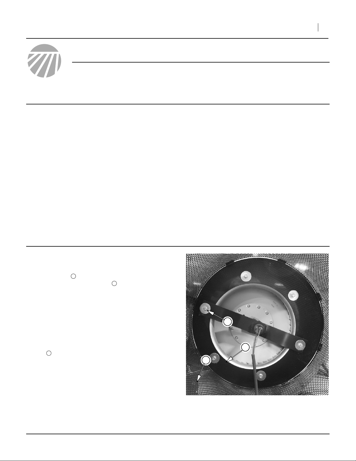
Refer to Figure 2
Inspect the mounting orientation of your hydraulic fan.
The flange has an eccentric shape, and the narrowest
part of the flange needs to be adjacent to the location
where the new fan control will go . If it is not mounted
this way, complete the following steps:
1. Remove and save the 6 bolts holding the cap
screen on the fan cage (not shown). Note the orientation of any fan block baffle on the cage.
2. Disconnect the fan sensor connector, remove any
protective grommet at the screen hole, and pull the
sensor lead inside the cage.
3. Remove and save the bolts holding the flange to the
3
fan .
4. Rotate the fan into the orientation depict at right.
Re-insert the flange mounting bolts and secure.
5. If the fan has a blocking baffle, remove its fasteners
and re-mount it as it was previously oriented.
6. Cut a new hole for the sensor lead, at screen bottom, but clear of the operating area for the new control. Re-insert grommet. Seal old hole.
7. Re-attach cage screen cap.
1
2
Establish that your fan has the necessary pre-drilled and
tapped holes for mounting kit components; some fans
may not. More typically, the holes are present and contain a bolt and plastic plugs.
If necessary, move the implement to a dry well-lighted
location suitable for disassembly.
Park and secure the implement. Secure the tractor if left
connected.
Disconnect any hydraulic and electrical power to the
implement
Have the following tools at hand:
•1⁄4-20 UNC tap and tap wrench, #7 drill bit and drill
• Basic hand tools (including a right-angle flat-bladed
screwdriver)
• Fine-tip washable marker
3
1
2
Figure 1
Fan Flange
25392
©Copyright 2006 Printed 01/23/2008 401-463M
Page 2
2 Fan Butterfly Valve Kit
The fan valve control is mounted on the inlet face of the
fan housing.
Great Plains Mfg., Inc.
8. Loosen hose clamp and remove 6in fan hose .
Refer to Figure 2
9. Remove bolts or knock plastic plugs out of fan shaft
3
holes . Any bolts/plugs in these holes are not reused.
10. Check that these holes are at least3⁄8in diameter.
Use the fan shutter control shaft to check fit. The
shaft must pass through both holes, and pivot
freely. If the shaft does not fit, or binds, use a
13
⁄32in drill to enlarge the hole(s).
11. Unscrew bolt at bolt hole . Any bolt and any
washer present are not re-used.
If the hole is not drilled and tapped for1⁄4-20, drill a
#7 pilot hole and tap the hole.
12. If there is a cast detail similar to on the back side
5
at , leave it plugged. It is not used by this kit.
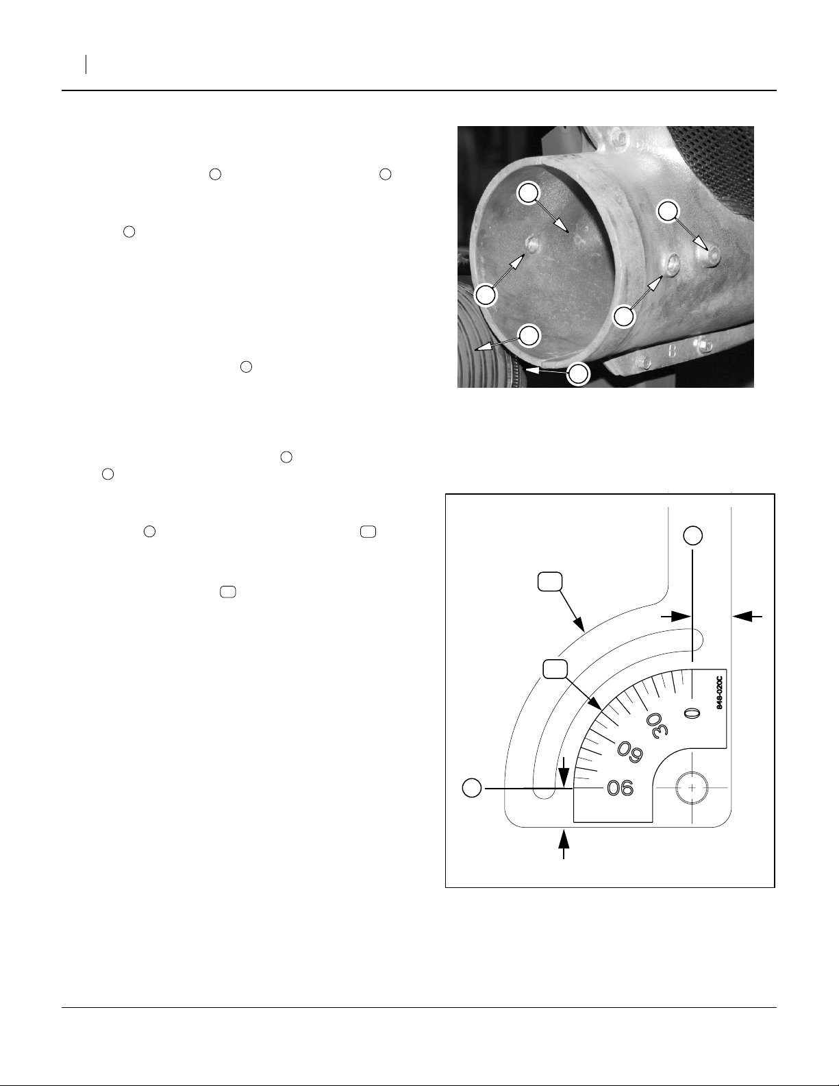
Refer to Figure 3
13. Using a washable fine-tip marker and a ruler, draw
two lines on the face of the shutter control .
Each is1⁄2in from the edge of the plate, and on the
shaft centerline.
14. Apply the scale decal so that the “0” and “90”
degree marks align with the lines drawn.
412
1 2
4
4
18
5
4
3
3
2
1
Figure 2
Fan Preparation
25136
4
12
0.5in
18
4
401-463M 01/23/2008
0.5in
Figure 3
Apply Decal to Scale
25137
Page 3

Great Plains Mfg., Inc.
Refer to Figure 4
15. Insert the fan shutter control shaft in the shaft
holes.
12
Installation Instructions 3
16. Loosely install the1⁄4-20 x 1in bolt and washer
in the control’s slot.
17. Rotate the control to fully open (0 degrees on the
scale), and tighten the1⁄4-20 bolt.
Refer to Figure 5
18. Place the fan shutter disk on top of the shaft ,
and temporarily hold it there by inserting the two 10-
24 screws .
19. Using the #10 lock washers and 10-24 nuts ,
tighten the screws.
20. Slide the 6in air hose (not shown) back over the fan
outlet and tighten the clamp (not shown).
13
13 12
19 20
16 15
12
13
Figure 4
Insert Shaft
15
16
20
19
25138
15
16
12
14
Figure 5
Mount Shutter Disk
14
25139
01/23/2008 401-463M
Page 4

Great Plains Mfg., Inc.
4 Fan Butterfly Valve Kit
Apply Decals
The new caution decals are placed on the back face
of the main toolbar, between row units. The following
table contains suggested locations “D” for various planter
configurations.
Clean and dry each location. Peel the release paper from
the decal. Apply it and smooth out air bubbles with a soft
cloth.
0
1
12-Row DDDDDD
12-Row Twin DDDDD
16-Row D D D D D D
16-Row Twin D D D D D D
17
17
0
0
0
0
0
0
0
0
1
1
1
1
1
2
3
4
5
6
7
8
9
0
1
2
3
4
Using the Butterfly Valve
1
1
5
6
In most cases, Great Plains anticipates that the butterfly
valve will be left at 0 degrees (wide open), and that seed
flow and fan speed will be properly regulated by the tractor hydraulic system.
If your tractor is unable to satisfactorily regulate, but can
produce adequate pressure and flow to operate the fan at
or above recommended speeds, then this valve may be
helpful in regulating air flow.
In general, the valve has little effect below a 20 degree
setting and too much effect above 45 degrees. The practical operating range is between 20 and 30 degrees.
For best results, always attempt to operate the fan motor
at the rpm settings called for in the Operator’s Manual.
Parts List
401-457K Fan Butterfly Valve Kit
Your kit includes:
Callout Quantity Part No. Part Description
11
12
13
14
15
16
17
18
19
20
1 401-463M This manual
1 401-363H CRARY FAN SHUTTER
1 411-030D CRARY FAN SHUTTER DISK
2 801-055C SCREW RD HD 10-24 X 1 PLT
2 803-268C NUT HEX NYLOCK 10-24 PLT
2 804-054C WASHER LOCK #10
6 838-993C DECAL DO NOT LOCK UP REAR ROW
1 848-020C DECAL FAN BAFFLE INDEX
1 801-151C SCR HEX SELF TAP 1/4-20X1TYPEF
1 804-075C WASHER FLAT 1/4 USS PLT
Great Plains Manufacturing, Inc.
Corporate Office: PO Box 5060
Salina, KS 67402-5060 USA
401-463M 01/23/2008
 Loading...