

Great Plains EWNT7 1523Q-1630Q Operator Manual
Operator’s Manual
EWNT7 and EWNT10
End Wheel No Till Drill
Model Serial No.
EWNT7 1523Q - 1630Q
EWNT10 4142U - 4568U
Manufacturing, Inc.
www.greatplainsmfg.com
Read the operator’s manual entirely. When you see this symbol, the subsequent in-
!
structions and warnings are serious - follow without exception. Your life and the lives of
others depend on it!
© Copyright 1999 Printed
4/12/2005
13844
Cover illustration may show optional equipment not supplied with standard unit.
150-082M-A

General Information
Important Notice
Great Plains Manufacturing, Inc. provides this publication “as is” without warranty of any kind, either expressed or implied. While every precaution has been
taken in the preparation of this manual, Great Plains
Manufacturing, Inc. assumes no responsibility for errors or
omissions. Neither is any liability assumed for damages
resulting from the use of the information contained herein. Great Plains Manufacturing, Inc. reserves the right to
revise and improve its products as it sees fit. This publi-
This Operator’s Manual applies to the
7’ & 10’ End Wheel No-Till
Owner’s Information
Name: _____________________________________
cation describes the state of this product at the time of its
publication, and may not reflect the product in the future.
Printed in the United States of America.
For your convenience, record your Serial Number, Model Number and the Date Purchased in the spaces provided below. Have this information available when
calling your Great Plains Authorized Dealer.
Serial Number ________________
Address ____________________________________
City________________State ____ Zip ___________
Phone_______________________
Name of Dealership ___________________________
Dealer’s Name _______________________________
Address ____________________________________
City________________State ____ Zip ___________
Phone_______________________
Model Number ________________
Date Purchased _______________
EWNT7 and EWNT10 End Wheel No Till Drill 150-082M-A 4/25/06Great Plains Mfg., Inc.

Table of Contents
Introduction. . . . . . . . . . . . . . . . . . . . . . . . . . . . . . . . . . . . 2
Using this Manual . . . . . . . . . . . . . . . . . . . . . . . . . . . . . . . 2
Section 1 Safety Rules . . . . . . . . . . . . . . . . . . . . . . . . . . . 3
General Operation & Repair . . . . . . . . . . . . . . . . . . . . 3
Transporting. . . . . . . . . . . . . . . . . . . . . . . . . . . . . . . . . 3
Tire Handling & Repair . . . . . . . . . . . . . . . . . . . . . . . . 3
Safety Decals. . . . . . . . . . . . . . . . . . . . . . . . . . . . . . . . 3
Section 2 Assembly Instructions & Set-Up . . . . . . . . . . 6
Tire Inflation Chart . . . . . . . . . . . . . . . . . . . . . . . . . . . . 6
Torque Values Chart for Common Bolt Sizes . . . . . . . 6
Pre-Assembly Checklist. . . . . . . . . . . . . . . . . . . . . . . . 7
Tractor Requirements . . . . . . . . . . . . . . . . . . . . . . . . . 8
Tractor Drawbar Hook-Up . . . . . . . . . . . . . . . . . . . . . . 8
Tractor Drawbar Hook-Up For Ball Swivel Hitch . . . . . . 8
Tractor Hydraulic Hook-Up. . . . . . . . . . . . . . . . . . . . . . 9
Bleeding the Hydraulic Lifting System . . . . . . . . . . . . . 9
Section 3 Basic Operation . . . . . . . . . . . . . . . . . . . . . . . 10
Operating the Lifting Hydraulic System . . . . . . . . . . . 10
Transporting. . . . . . . . . . . . . . . . . . . . . . . . . . . . . . . . 10
Operating Transport Lock . . . . . . . . . . . . . . . . . . . . . 10
Lock Out Hubs . . . . . . . . . . . . . . . . . . . . . . . . . . . . . . 10
Section 4 Adjustments . . . . . . . . . . . . . . . . . . . . . . . . . . 11
Drive System Clutch . . . . . . . . . . . . . . . . . . . . . . . . . 11
Drive Train Operation. . . . . . . . . . . . . . . . . . . . . . . . . 11
Seeding Rate . . . . . . . . . . . . . . . . . . . . . . . . . . . . . . . 12
Change Drive Sprockets . . . . . . . . . . . . . . . . . . . . . . 12
Set Seed-Rate Handle. . . . . . . . . . . . . . . . . . . . . . . . 12
Position Seed-Cup Doors . . . . . . . . . . . . . . . . . . . . . 12
Check Seeding Rate . . . . . . . . . . . . . . . . . . . . . . . . . 13
Seed Rate Charts . . . . . . . . . . . . . . . . . . . . . . . . . . . 14
Fertilizer Drive . . . . . . . . . . . . . . . . . . . . . . . . . . . . . . 19
Fertilizer Rate . . . . . . . . . . . . . . . . . . . . . . . . . . . . . . . 19
7’ & 10’ Fertilizer Application Chart . . . . . . . . . . . . . . . 19
Native Grass Drive . . . . . . . . . . . . . . . . . . . . . . . . . . . 20
Native Grass Rate . . . . . . . . . . . . . . . . . . . . . . . . . . . . 20
Native Grass Seeding Adjustments. . . . . . . . . . . . . . . 20
Native Grass Seed Rate Charts & Sprockets . . . . . . . 21
Planting Depth Adjustments . . . . . . . . . . . . . . . . . . . . 22
Coulter Hydraulic Depth Control . . . . . . . . . . . . . . . . . 22
Down Pressure Requirements . . . . . . . . . . . . . . . . . . 22
Individual Opener & Coulter . . . . . . . . . . . . . . . . . . . . 23
Disk Opener Spring Pressure Setting . . . . . . . . . . . . . 23
Individual Opener Height. . . . . . . . . . . . . . . . . . . . . . . 23
Opener Press Wheel Depth . . . . . . . . . . . . . . . . . . . . 24
Press Wheel Angle . . . . . . . . . . . . . . . . . . . . . . . . . . . 24
Section 5 Field Operations . . . . . . . . . . . . . . . . . . . . . . . 25
Drill Preparations. . . . . . . . . . . . . . . . . . . . . . . . . . . . . 25
Operating Checklist . . . . . . . . . . . . . . . . . . . . . . . . . . . 25
Section 6 Maintenance & Lubrication. . . . . . . . . . . . . . . 26
Maintenance . . . . . . . . . . . . . . . . . . . . . . . . . . . . . . . . 26
Fertilizer Unit . . . . . . . . . . . . . . . . . . . . . . . . . . . . . . . . 26
Storage . . . . . . . . . . . . . . . . . . . . . . . . . . . . . . . . . . . . 26
Lubrication. . . . . . . . . . . . . . . . . . . . . . . . . . . . . . . . . . 26
Section 7 Troubleshooting . . . . . . . . . . . . . . . . . . . . . . . 29
Section 8 Specifications & Warranty . . . . . . . . . . . . . . . 31
4/25/06 Great Plains Mfg., Inc. EWNT7 and EWNT10 End Wheel No Till Drill 150-082M-A
-1
Using this Manual
Using this Manual
For your safety and to help in developing a better understanding of your equipment, read this manual. Reading
these sections not only provides valuable training but
Introduction
This manual has been prepared to instruct you in the
safe and efficient operation of your End Wheel No-Till.
Read and follow all instructions and safety precautions
carefully.
The parts on your End Wheel No-Till have been specially designed and should only be replaced with genuine
Great Plains parts. Therefore, should your End Wheel
No-Till require replacement parts go to your Great
Plains Dealer.
The right hand and left hand as used throughout this
manual is determined by facing in the direction the machine will travel when in use unless otherwise stated.
Serial Number
The serial number plate is located on the front right side
of the frame. It is suggested that the serial number and
purchase date also be recorded for your convenience in
the space provided on the checklist page at the beginning of this manual.
The serial number provides important information about
your drill and may be required to obtain the correct replacement part. Always use the serial number and model number when sending correspondence or when
ordering parts from your Great Plains dealer.
also familiarizes you with helpful information and its location. After reviewing your manual store it in a dry, easily accessible location for future reference.
symbol, be alert and carefully read the message that follows it. In addition to design and configuration of equipment; hazard control and accident prevention are
dependent upon the awareness, concern, prudence and
proper training of personnel involved in the operation,
transport, maintenance and storage of equipment.
Watch for the following safety notations throughout your
operator’s manual:
!
Indicates an imminently hazardous situation which, if not
avoided, will result in death or serious injury. This signal
word is limited to the most extreme situations.
Indicates a potentially hazardous situation which, if not
avoided, could result in death or serious injury.
Indicates a potentially hazardous situation which, if not
avoided, may result in minor or moderate injury. It may
also be used to alert against unsafe practices.
DANGER!
!
WARNING!
!
CAUTION!
!
The SAFETY ALERT SYMBOL indicates that there is a
potential hazard to personal safety involved and extra
safety precautions must be taken. When you see this
2
EWNT7 and EWNT10 End Wheel No Till Drill 150-082M-A 4/25/06
NOTE: Indicates a special point of information which
requires your attention.
Great Plains Mfg., Inc.

Section 1 Safety Rules
Section 1 Safety Rules
Most accidents are the result of negligence and carelessness, usually caused by failure of the operator to follow simple but necessary safety precautions. The
following safety precautions are suggested to help prevent such accidents. The safe operation of any machinery is a big concern to consumers and
manufacturers.Your End Wheel No-Till has been designed with many built-in safety features. However, no
one should operate this product before carefully reading
this operator’s manual.
!
General Operation & Repair
1. Never allow the drill to be operated by anyone who is unfamiliar with the operation of all functions of the unit. All
operators should read and thoroughly understand the instructions given in this manual prior to moving the unit.
2. Make sure safety rules are understood before operating
machinery or tractor.
3. Never permit any persons other than the operator to ride
on the tractor.
4. Never permit any persons to ride on or stand near the
drill while it is in operation.
5. Regulate your speed to the field conditions, maintaining
complete control at all times.
6. After repairing or adjusting, make sure all tools and
parts are removed from the implement before attempting
to operate it.
7. Do not grease or oil machine while it is in operation.
8. Loose fitting clothing should not be worn as it may catch
in moving parts.
9. Never dismount from a moving tractor.
10. Do not leave the tractor or the implement unattended
with the engine running.
11. Do not stand between the tractor and the implement during hitching.
12. Detach and store implements in an area where children
normally do not play. Stabilize implements by using suitable supports and block wheels.
13. If a hydraulic leak develops, correct it immediately. Escaping hydraulic oil can have extremely high pressure. A
stream of high pressure oil may easily penetrate the skin.
It is imperative that the connections are tight and that all
lines and pipes are in good condition. If an injury is
caused by the escaping hydraulic fluid, see doctor at
once!
14. Use a piece of cardboard or wood to detect leaks of hydraulic oil under pressure.
15. Be sure to relieve all hydraulic pressure before disconnection any lines or pipes between the implement and the tractor hydraulic system. Keep all guards and shields in place.
Transporting
1. Use good judgement when transporting tractor and implements on the highway. Always maintain complete control of the machine.
2. Limit transport speed to 20 mph. Transport only with a
farm tractor of sufficient size and horse power. See
“Tractor Requirements” Section 2,page 8.
3. Always make sure flashing safety lights, “Slow Moving
Vehicle” emblem, and reflectors are in place and visible
prior to transporting the machine on public roads.
4. Know your state and local laws concerning highway
safety and regulations. Comply with these laws when
transporting machinery.
5. Use warning flags or approved warning lights at night
and during other periods of poor visibility. Do your best
to prevent highway accidents.
Tire Handling & Repair
1. Tire changing can be dangerous and should be preformed by trained personnel using the correct tools and
equipment.
2. Do not re-inflate a tire that has been run flat or seriously
under inflated. Have it checked by qualified personnel.
3. When removing and installing wheels, use wheel handling equipment adequate for the weight involved.
Safety Decals
1. Your End Wheel No-Till comes equipped with all safety
decals in place. They were designed to help you safely
operate your drill. Read and follow their directions.
2. Keep safety decals clean and legible.
3. Replace all damaged or missing safety decals. To order
new safety decals go to your Great Plains dealer and refer to the parts section for safety decal package part number.
4. Replace these decals whenever they become worn or unreadable. To install new safety decals:
a. Clean the area the decal is to be placed
b. Peel backing from the decal. Press firmly on to sur-
face being careful not to cause air bubbles under the
decal.
4/25/06 Great Plains Mfg., Inc.
EWNT7 and EWNT10 End Wheel No Till Drill 150-082M-A
-3
Section 1 Safety Rules
13846
13846
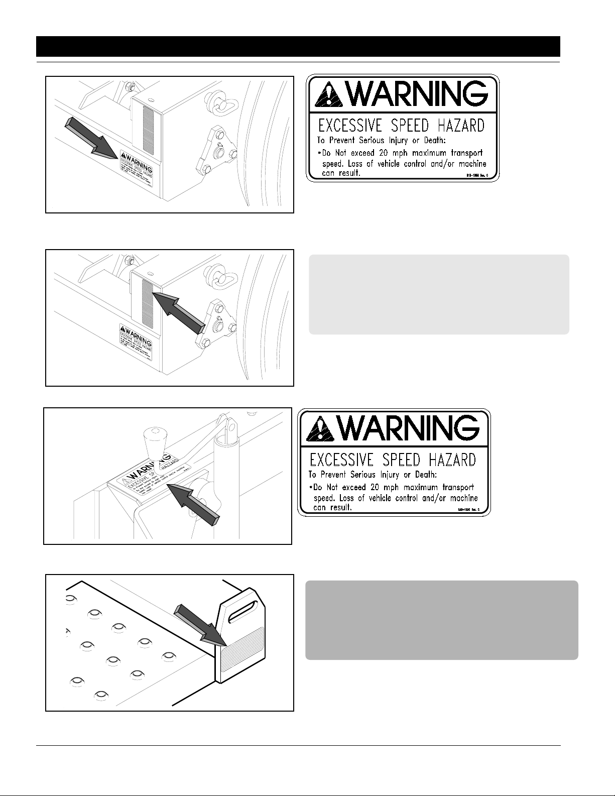
818-188C
Transport Speed Warning
838-265C
Amber Reflectors
13847
818-188C
Transport Speed Warning
838-266C
13849
4
EWNT7 and EWNT10 End Wheel No Till Drill 150-082M-A 4/25/06
Red Reflector
Great Plains Mfg., Inc.
Section 1 Safety Rules
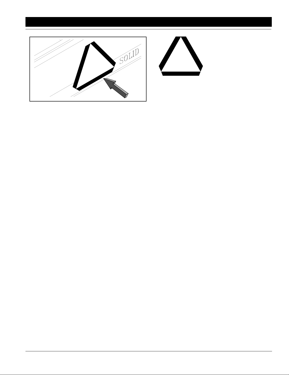
13848
818-003C
Slow Moving Vehicle Emblem
4/25/06 Great Plains Mfg., Inc.
EWNT7 and EWNT10 End Wheel No Till Drill 150-082M-A
-5
Section 2 Assembly Instructions & Set-Up
Section 2 Assembly Instructions & Set-Up
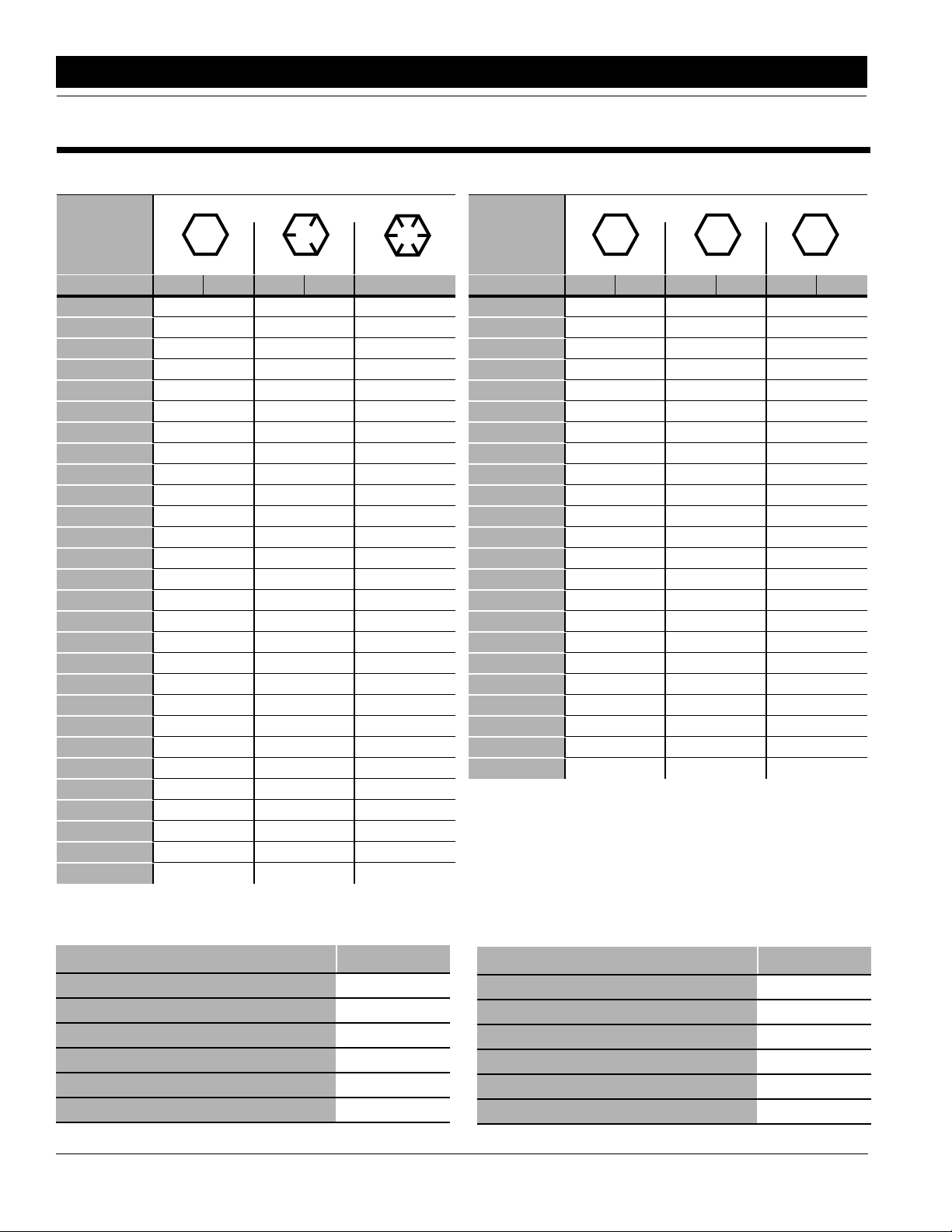
Torque Values Chart for Common Bolt Sizes
Bolt Head Identification
Bolt Head Identification
Bolt Size
(Inches)
1
in-tpi
1/4" - 20 7.4 5.6 11 8 16 12 M 5 X 0.8 436597
1/4" - 28 8.5 6 13 10 18 14 M 6 X 1 7 5 11 8 15 11
5/16 - 18 15 11 24 17 33 25 M 8 X 1.25 17 12 26 19 36 27
5/16" - 24 17 13 26 19 37 27 M 8 X 1 18 13 28 21 39 29
3/8" - 16 27 20 42 31 59 44 M10 X 1.5 33 24 52 39 72 53
3/8" - 24 31 22 47 35 67 49 M10 X 0.75 39 29 61 45 85 62
7/16" - 14 43 32 67 49 95 70 M12 X 1.75 58 42 91 67 125 93
7/16" - 20 49 36 75 55 105 78 M12 X 1.5 60 44 95 70 130 97
1/2" - 13 66 49 105 76 145 105 M12 X 1 90 66 105 77 145 105
1/2" - 20 75 55 115 85 165 120 M14 X 2 92 68 145 105 200 150
9/16" - 12 95 70 150 110 210 155 M14 X 1.5 99 73 155 115 215 160
9/16" - 18 105 79 165 120 235 170 M16 X 2 145 105 225 165 315 230
5/8" - 11 130 97 205 150 285 210 M16 X 1.5 155 115 240 180 335 245
5/8" - 18 150 110 230 170 325 240 M18 X 2.5 195 145 310 230 405 300
3/4" - 10 235 170 360 265 510 375 M18 X 1.5 220 165 350 260 485 355
3/4" - 16 260 190 405 295 570 420 M20 X 2.5 280 205 440 325 610 450
7/8" - 9 225 165 585 430 820 605 M20 X 1.5 310 230 650 480 900 665
7/8" - 14 250 185 640 475 905 670 M24 X 3 480 355 760 560 1050 780
1" - 8 340 250 875 645 1230 910 M24 X 2 525 390 830 610 1150 845
1" - 12 370 275 955 705 1350 995 M30 X 3.5 960 705 1510 1120 2100 1550
1-1/8" - 7 480 355 1080 795 1750 1290 M30 X 2 1060 785 1680 1240 2320 1710
1 1/8" - 12 540 395 1210 890 1960 1440 M36 X 3.5 1730 1270 2650 1950 3660 2700
1 1/4" - 7 680 500 1520 1120 2460 1820 M36 X 2 1880 1380 2960 2190 4100 3220
1 1/4" - 12 750 555 1680 1240 2730 2010
1 3/8" - 6 890 655 1990 1470 3230 2380
1 3/8" - 12 1010 745 2270 1670 3680 2710
1 1/2" - 6 1180 870 2640 1950 4290 3160
1 1/2" - 12 1330 980 2970 2190 4820 3560
Grade 2 Grade 5
N · m2ft-lb3N · m ft-lb N · m ft-lb mm x pitch4N · m ft-lb N · m ft-lb N · m ft-lb
Grade 8
Bolt Size
(Metric)
1
in-tpi = nominal thread diameter in inches–threads per inch
2
N· m = newton-meters
3
ft-lb= foot pounds
4
mm x pitch = nominal thread dia. in millimeters x thread pitch
5.8 8.8 10.9
Class 5.8 Class 8.8 Class 10.9
Tire Inflation Chart
Tire Size Inflation PSI
7.50 x 20" 4-Ply Drill Rib 28
9.0 x 22.5 10-Ply Highway Service 70 70
9.0 x 24" 8-Ply Rib Implement 40
9.5L x 15" 6-Ply Rib Implement 32
9.5L x 15" 8-Ply Rib Implement 44
9.5L x 15" 12-Ply Rib Implement 60
6
EWNT7 and EWNT10 End Wheel No Till Drill 150-082M-A 4/25/06
Tire Size Inflation PSI
11L x 15" 6-Ply Rib Implement 28
11L x 15" 12-Ply Rib Implement 52
12.5L x 15" 8-Ply Rib Implement 36
12.5L x 15" 10-Ply Rib Implement 44
16.5L x 16.1" 10-Ply Rib Implement 36
41 x 15" x 18 - 22-Ply Rib Implement 44
Great Plains Mfg., Inc.
Section 2 Assembly Instructions & Set-Up
Pre-Assembly Checklist
Check
All major components
Fasteners that were shipped with the End Wheel No-Till Drill.
NOTE: Some of the hardware from the factory has been installed in the location where it will be used.
Have a minimum of 2 people at hand while assembling the End Wheel No-Till Drill.
Have a fork lift or loader along with chains and safety stands ready for the assembly task.
If you are unsure where a fastener is used, use the parts section of this manual to identify it. Be sure the part gets
used in the correct location.
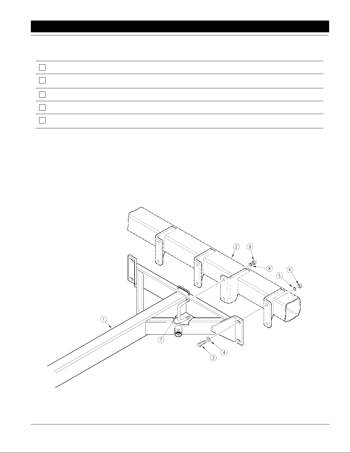
Refer to Figure 2-1:
Before starting the drill assembly, be sure that the drill
frame is safely supported and the end wheel tires are
blocked.
Bolt the outside legs of the tongue weldment (#1) to the
drill frame (#2) using 3/4" x 2 1/4" long bolts (#3), 3/4"
SAE flat washers (#4), 3/4" lock washers (#5), and 3/4"
hex nuts (#6).
Connect the rear tube of the tongue (#1) to the drill frame
(#2) using 3/4" x 6 1/32" x 3 1/4" long u-bolts (#7), 3/4"
lock washers (#8), and 3/4" hex nuts (#9).
Tighten all hardware to the torque specification listed in
the "Nut & Bolt Torquing Chart" on page 6.
4/25/06 Great Plains Mfg., Inc.
Tongue & Pull Bar Assembly
Figure 2-1
EWNT7 and EWNT10 End Wheel No Till Drill 150-082M-A
10681
-7
Section 2 Assembly Instructions & Set-Up
Tractor Requirements
To operate your Great Plains End Wheel No-Till Drill in
most field conditions, a tractor of adequate size should
be used. For 7’ drills, a 55 horsepower tractor is required. For 10’ drills, a 75 horsepower tractor is required.
7’ and 10’ drills require one set of remote outlets.
Tractor Drawbar Hook-Up
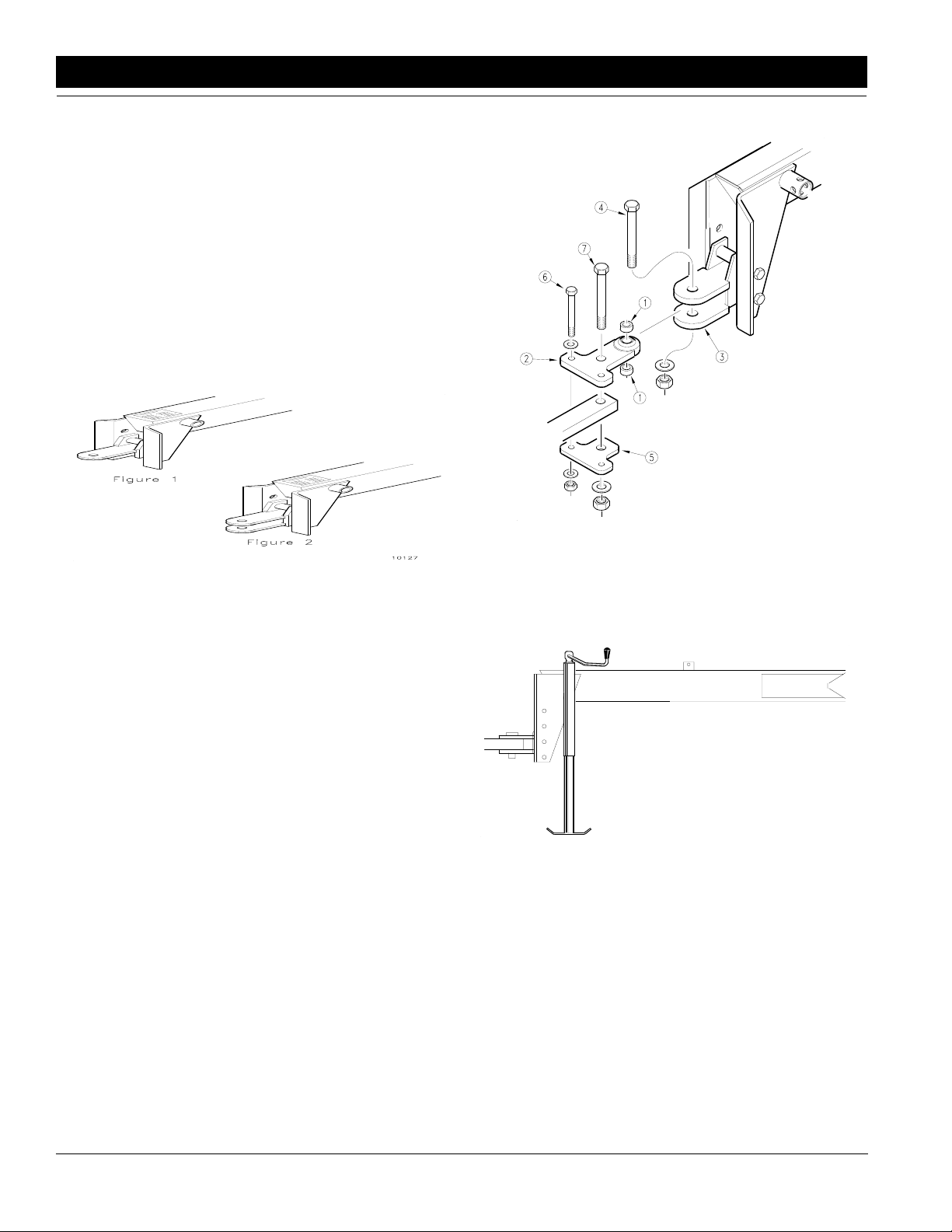
Refer to Figure 2-2 & Figure 2-3:
The Great Plains No-Till Drill is equipped with either a
single strap, Figure 2-2, clevis style hitch, Figure 2-3, or
a ball swivel hitch, Figure 2-5. For proper field operation,
the tongue of the drill should run level, parallel to the
ground in field position.
11549
10127
Single Strap Hitch
Figure 2-2
Clevis Style Hitch
Figure 2-3
Tractor Drawbar
Hook-Up For Ball Swivel Hitch
Refer to Figure 2-4:
Place a spacer tube (#9) above and below the ball swivel. Bolt the ball swivel {top hitch weldment} (#1) and
spacer tubes (#9) to the drill clevis hitch with a 1" x 5"
long bolt (#10), 1" USS flat washer (#11), and 1" nylock
nut (#12).
Back the tractor to the drill hitch. Using the screw jack,
adjust the drill tongue up or down to center the drawbar
below the upper hitch plate (#1). Place hitch weldment
(#1) on top of the tractor drawbar, aligning the rear hole
in the hitch weldment with the large hole in the drawbar.
Place the lower hitch plate (#2) under the drawbar and
attach to the hitch weldment (#1) with {2} 5/8" x 4" long
bolts (#3), 5/8" flat washers (#4), 5/8" nylock nuts (#5).
Bolt the top hitch weldment (#1) through the hole in the
drawbar to the lower hitch plate (#2) with a 1" x 5 1/2"
long bolt (#6), 1" USS flat washer (#7), and 1" nylock nut
(#8).
Ball Swivel Hitch
Figure 2-4
Refer to Figure 2-5:
1. With the drill lowers and in the field position, adjust
the tongue jack to level the tongue.
Jack In Vertical Position
Figure 2-5
2. Back the tractor draw bar up to the drill hitch to determine the amount of adjustment required.
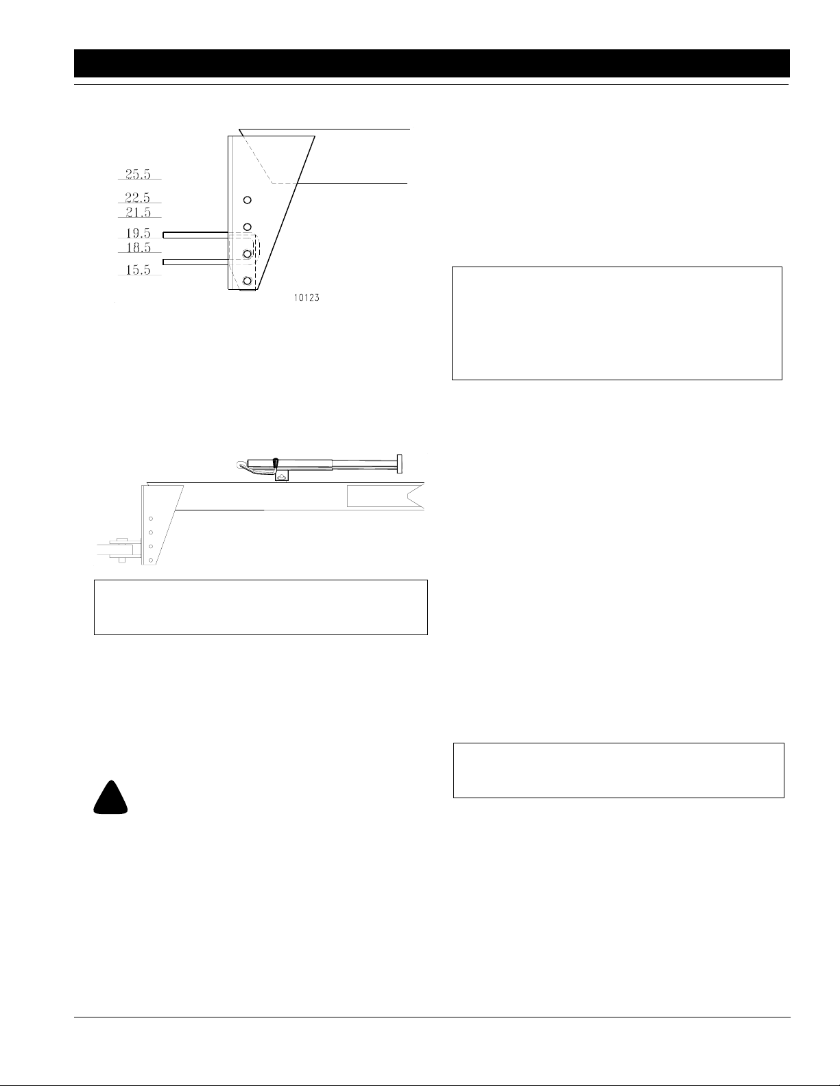
Refer to Figure 2-6:
3. The mounting holes in the hitch have been offset so
the hitch can be turned over and bolted on in three
different hitch positions, giving you six different hitch
heights.
10150
8
EWNT7 and EWNT10 End Wheel No Till Drill 150-082M-A 4/25/06
Great Plains Mfg., Inc.
Section 2 Assembly Instructions & Set-Up
Bleeding the
Hydraulic Lifting System
The implement lifting system is equipped with rephasing
type hydraulic cylinders that require a special procedure
for bleeding air from the hydraulic circuits. Read and follow the procedure carefully. The rephasing type cylinders will not function properly with air in the hydraulic
circuit. Bleeding the system may have been done during
initial set up of the drill.
10123
Hitch Height Adjustment
Figure 2-6
4. Connect the hitch to the tractor using a pin of adequate strength (minimum 1" diameter).
Refer to Figure 2-7:
5. Unpin the tongue jack, and pin it on top of the
tongue.
Jack In Transport Position
Figure 2-7
NOTE: Make sure the hitch is securely bolted to the
drill tongue.
Your drill comes equipped with a hitch safety chain. The
safety chain should be securely attached to the drill hitch
and the tractor drawbar whenever towing or planting.
11833
Tractor Hydraulic Hook-Up
Route the lift hydraulic hoses along the tongue and
through the hose loop on the front of the tongue. Connect the hoses to the tractor remote outlets.
NOTE: Check the hydraulic fluid in the tractor reservoir and fill to the proper level. Add fluid to the system as needed. A low reservoir level may draw air
back into the system, causing jerky or uneven cylinder movements. The drill system capacity is approximately 1 gallon.
1. Jack up and support the front member of the drill at
a point close to each end wheel. If the end wheel cylinders have previously been engaged, they may be
used to assist in raising the frame.
2. With the frame blocked and supported, unpin the
cylinders from the drill frame and turn the cylinders
upside down and wire or otherwise safely support
the rod end port higher than the base end port.
3. With the tractor engine at an idle speed, hold the remote lever on to put fluid into the lifting circuit. When
the cylinders have completely extended, hold the remote lever on for one minute.
4. Retract the cylinders. Extend the cylinders again
and hold the remote lever on for one more minute.
Repeat this step two more times to completely bleed
the system.
5. Repin the cylinders to the drill frame, rod end to the
wheel arm. If air is trapped in either cylinder, the affected cylinder will have a spongy, erratic movement
and the drill will not raise evenly. Refill the tractor hydraulic fluid reservoir to its proper level.
NOTE: After the drill is raised, a slight settling will occur due to the action of the rephasing cylinders.
!
Escaping fluid under pressure can have sufficient force to penetrate the skin. Check all hydraulic lines and hoses before applying pressure. Fluid escaping from a very small hole can be
almost invisible. Use paper or cardboard, not body parts, to
check for suspected leaks. If injured, seek medical assistance
from a doctor that is familiar with this of injury. Foreign fluids
in the tissue must be surgically removed within a few hours or
gangrene will result.
4/25/06 Great Plains Mfg., Inc.
CAUTION!
IMPORTANT: When using sealant on pipe threads the
friction between the threads is reduced; therefore, be
certain not to over tighten causing damage to the cylinder port or fitting.
EWNT7 and EWNT10 End Wheel No Till Drill 150-082M-A
-9
 Loading...